JP4394696B2 - Tablet dispensing device - Google Patents
Tablet dispensing device Download PDFInfo
- Publication number
- JP4394696B2 JP4394696B2 JP2007052755A JP2007052755A JP4394696B2 JP 4394696 B2 JP4394696 B2 JP 4394696B2 JP 2007052755 A JP2007052755 A JP 2007052755A JP 2007052755 A JP2007052755 A JP 2007052755A JP 4394696 B2 JP4394696 B2 JP 4394696B2
- Authority
- JP
- Japan
- Prior art keywords
- gear
- tablet
- tablet cassette
- support base
- cassette
- Prior art date
- Legal status (The legal status is an assumption and is not a legal conclusion. Google has not performed a legal analysis and makes no representation as to the accuracy of the status listed.)
- Expired - Lifetime
Links
Images


Description
本発明は、錠剤分配装置に関するものであり、より詳しくはモーター等の駆動手段の駆動により、錠剤カセッター内に収容された錠剤を分配ローターによって所定数ずつ取り出すための錠剤分配装置に関するものである。 The present invention relates to a tablet dispensing device, and more particularly to a tablet dispensing device for taking out a predetermined number of tablets stored in a tablet cassette by a dispensing rotor by driving a driving means such as a motor.
従来より、この種の錠剤分配装置としては、種々のものが提案されており、例えば下記特許文献1、特許文献2所載のものが公知である。 Conventionally, various devices have been proposed as this type of tablet dispensing device. For example, those disclosed in Patent Document 1 and Patent Document 2 below are known.
これらの公報所載の装置は何れも、錠剤カセッターのみを支持台より取り出すことができ、カセッターを取り出した状態で錠剤の詰め替え等ができ、その作業性が極めて簡便であった。
しかしながら、上記何れの従来例所載の錠剤分配装置にあっても、支持台及びカセッターに夫々設けられた凸部と溝部とのスライドにより支持台に対してカセッターの左右方向の位置決めをして収納させるものであり、このスライドの為には凸部と溝部との間に若干の隙間(遊び)を持たせておく必要があった。 However, in any of the above-described conventional tablet dispensing apparatuses, the cassette is positioned in the left-right direction with respect to the support base by the slide of the projection and the groove provided on the support base and the cassette, respectively. For this slide, it was necessary to have a slight gap (play) between the convex portion and the groove portion.
しかるに、錠剤カセッター及び支持台は一般的に夫々プラスチック等により一体成形されるものであり、成形時の誤差等を考慮して、錠剤カセッター及び支持台に夫々誤差が生じても凸部と溝部との間に隙間が生ずるように設計されている。 However, the tablet cassette and the support table are generally integrally formed of plastic or the like, and in consideration of errors during molding, even if errors occur in the tablet cassette and the support table, the convex portion and the groove portion are formed. It is designed to create a gap between the two.
このため、成形時の誤差によって凸部が小さくなり溝部が広くなったものについては、両者の隙間部分が大きくなり過ぎ、収納された錠剤カセッターにガタツキが生じるという問題点を有していた。 For this reason, when the convex portion is reduced and the groove portion is widened due to an error during molding, there is a problem that the gap portion between the two becomes too large and the stored tablet cassette is rattled.
また、このように凸部と溝部との隙間部分が大きい場合には、錠剤カセッターを取付ける際に、収容時に係合しあう歯車同士或いはコネクター同士が不用意に接触してしまい、これらの部位が破損するおそれも存在した。 In addition, when the gap portion between the convex portion and the groove portion is large in this way, when the tablet cassette is attached, the gears or connectors that are engaged with each other at the time of storage are inadvertently contacted, and these portions are There was also a risk of damage.
そこで、本発明はこのような問題を解決すべくなされたものであり、左右方向のブレを確実に防止しつつ、正確に錠剤カセッターを支持台に収納せしめることのできる錠剤分配装置を提供することを課題とする。 Accordingly, the present invention has been made to solve such a problem, and provides a tablet dispensing apparatus that can accurately store a tablet cassette on a support base while reliably preventing lateral blur. Is an issue.
本発明は、分配ローター33を内在し、該分配ローター33が回転することで錠剤が一錠ずつ排出されるよう構成される錠剤カセッター30と、該錠剤カセッター30を着脱自在に支持する支持台10と、前記分配ローター33に連結され、前記錠剤カセッター30の下部から突設される従属ギヤ35と、分配ローター33を回転させるための駆動手段に連結され、前記支持台10から突設され、錠剤カセッター30を支持台10に収納した際に前記従属ギヤ35と噛合するギヤ12とを備え、支持台10には、前記ギヤ12の両側方を覆う左右一対の側板14a,14aが突設され、錠剤カセッター30の下部には、外周面に弾性体42が捲回される左右一対の回転ローラー41が突設され、錠剤カセッター30を支持台10に収納した際には、前記各回転ローラー41の弾性体42が各側板14a,14aと当接して圧接した状態となり、錠剤カセッター30を支持台10上で移動させて錠剤カセッター30を支持台10に収納する又は支持台10から取り出す際には、前記各回転ローラーの弾性体42が各側板14a,14aと当接して各回転ローラー41が回転するよう構成されていることを特徴とする。
The present invention includes a
本発明の錠剤分配装置では、弾性体42はリング状のゴム部材であり、回転ローラー41の外周面には凹溝41aが形成され、該凹溝41aに前記リング状のゴム部材が介在されていることを特徴とする。
In the tablet dispensing device of the present invention, the
本発明に係る錠剤分配装置は、錠剤カセッターの下部の回転ローラーには外周面に弾性体が捲回されてなるため、回転ローラーの弾性体がギヤケースと当接し圧接した状態で、錠剤カセッターを収納せしめることができ、弾性体の弾性によって錠剤カセッターの左右方向のブレを防止することができるという効果を有する。 In the tablet dispensing device according to the present invention, an elastic body is wound around the outer peripheral surface of the rotary roller at the lower part of the tablet cassette, so that the tablet cassette is stored in a state where the elastic body of the rotary roller is in contact with and in pressure contact with the gear case. It has the effect that the blur of the tablet cassette can be prevented by the elasticity of the elastic body.
また、錠剤カセッターは支持台上を移動する際にもギヤケースに当接して回転する弾性体の弾性によって的確な位置に修正されるので、噛合わせるギヤの不用意な衝突をも防止でき、これらの部材の破損を防止することができるとともに、上記弾性体は回転自在な回転ローラーに捲回されてなるものゆえに、錠剤カセッターを収納、取り出す際には、弾性体はギヤケースに当接するものの、回転ローラーの回転によって円滑に収納、取り出すことができるという効果も奏する。 In addition, since the tablet cassette is corrected to the correct position by the elasticity of the elastic body that rotates in contact with the gear case when moving on the support table, it is possible to prevent inadvertent collision of the meshing gears. The member can be prevented from being damaged, and the elastic body is wound around a rotatable rotating roller. Therefore, when the tablet cassette is stored and taken out, the elastic body comes into contact with the gear case. There is also an effect that it can be smoothly stored and taken out by the rotation of the.
しかも、本発明は、錠剤カセッター等をプラスチック等により一体成形する場合であっても、成形時の誤差等は該弾性体の弾性によって吸収、つまり錠剤カセッターの回転ローターの位置と、支持台のギヤケースの位置とが、成形時に多少のズレ(誤差)を生じても、該ズレは弾性体の弾性によって吸収することができるという効果も有する。 Moreover, even when the tablet cassette or the like is integrally formed of plastic or the like, the present invention absorbs errors during molding by the elasticity of the elastic body, that is, the position of the rotary rotor of the tablet cassette and the gear case of the support base. Even if a slight deviation (error) occurs at the time of molding, the deviation can be absorbed by the elasticity of the elastic body.
また、本発明は、ギヤが支持台のギヤケースによって少なくとも左右が覆われて構成されてなるので、錠剤カセッターを収納、取出等の際に、不用意にギヤに錠剤カセッター等がぶつかり、ギヤが破損することを防止できるという効果をも有する。 In the present invention, since the gear is configured so that at least the left and right sides are covered with the gear case of the support base, when the tablet cassette is stored and taken out, the gear is accidentally collided with the gear and the gear is damaged. It has the effect that it can prevent.
さらに、本発明においては、上記回転ローラーが錠剤カセッター側に設けられているので、該回転ローラー等の取替え作業等を、躯体から錠剤カセッターを離脱した状態で行うことができるので、その作業が簡便である。 Furthermore, in the present invention, since the rotation roller is provided on the tablet cassette side, the replacement operation of the rotation roller and the like can be performed in a state in which the tablet cassette is detached from the housing, so that the operation is simple. It is.
また、錠剤カセッターの下部の従属ギヤが板バネによって回転が係止されてなるので、錠剤を詰め替えるために錠剤カセッターを取り出している時などは、板バネの係止により従属ギヤが回転することがなく、従属ギヤの回転による不用意な錠剤の落下等を防止することができるという効果を有するとともに、錠剤カセッターが収納されている際には、ギヤケースによって該板バネの従属ギヤの係止を解除して、該従属ギヤは支持台のギヤと噛合い、該ギヤの回転により従属ギヤを的確に回転させることができるという効果を有する。 In addition, since the subordinate gear of the lower part of the tablet cassette is locked by a leaf spring, the slave gear may be rotated by the latching of the leaf spring when the tablet cassette is taken out to refill the tablet. In addition, the tablet gear can be prevented from being accidentally dropped due to the rotation of the slave gear, and when the tablet cassette is stored, the slave gear unlocks the slave gear by the gear case. Thus, the subordinate gear meshes with the gear of the support base and has an effect that the subordinate gear can be accurately rotated by the rotation of the gear.
さらに、回転ローラーの外周面には凹溝が形成され、該凹溝にリング状のゴム部材が介在されてなるものゆえ、回転ローラーの凹溝にリング状のゴム部材を介在せしめることによって、極めて容易に回転ローラーに弾性体を捲回することができ、その製造コストの低減が図れるとともに、必要に応じて適宜弾性体の取替等も容易に行い得るという効果を有する。 Furthermore, a concave groove is formed on the outer peripheral surface of the rotating roller, and a ring-shaped rubber member is interposed in the concave groove. Therefore, by interposing a ring-shaped rubber member in the concave groove of the rotating roller, The elastic body can be easily wound around the rotating roller, the manufacturing cost can be reduced, and the elastic body can be easily replaced as needed.
以下、本発明の実施の形態について図1乃至図4を参酌しつつ、説明する。本実施形態における錠剤分配装置は、図1に示すように、円柱形の躯体1 と、該躯体1 から放射状に多数突設された扇状の支持台10, …と、各支持台10上に収納可能な錠剤カセッター30, …とから構成されてなる。なお、前記支持台10, …は、躯体1 から他段で突設されてなる。
Hereinafter, embodiments of the present invention will be described with reference to FIGS. 1 to 4. As shown in FIG. 1, the tablet dispensing apparatus in the present embodiment is stored in a columnar housing 1, fan-
ここで、躯体1 、支持台10、錠剤カセッター30は、夫々硬質のプラスチックにより一体成形されて製造される。
Here, the housing 1, the
支持台10には、躯体側の底部に錠剤を落下させるための錠剤通過孔11が穿設されてなる。
なお、該錠剤通過孔11の内面には、錠剤の通過を検出可能な検出手段たるセンサー(図示せず)が設けられてなる。
The
The inner surface of the
また、該錠剤通過孔11よりも前方(躯体に対して反対側)には、駆動手段たる回転モーター(図示せず)に連結されたギヤ12が、表出して設けられてなる。
Further, a
さらに、該ギヤ12の側方を覆うべく支持台10からギヤケース14が突設されてなる。
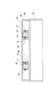
該ギヤケース14は、図2に示すように、ギヤ12の両側面を覆うべく設けられた左右一対の側板14a,14a と、該側板14a の一方から他方側に向けて僅かに伸びた前板14b とから構成されてなる。
Further, a
As shown in FIG. 2, the
前記錠剤カセッター30は、図1に示すように、上方で蓋31によって開閉自在に設けられたカセッター本体32の内部には、分配ローター33が内在されてなる。
As shown in FIG. 1, the
該カセッター本体32には、後方側の底部に錠剤を排出するための排出孔(図示せず)が穿設されてなり、前記分配ローター33は、回転することによりカセッター本体32内に収容された錠剤を一錠ずつ排出孔より排出して、該錠剤を支持台10の錠剤通過孔11より取り出せるよう構成されてなる。
尚、このようにして取り出された錠剤は、躯体1 に設けられた錠剤通路を介して、分包機等に送られることとなる。
The cassette body 32 is formed with a discharge hole (not shown) for discharging tablets at the bottom on the rear side, and the
The tablets taken out in this way are sent to a packaging machine or the like through a tablet passage provided in the casing 1.
また、分配ローター33の回転軸33a はカセッター本体32の下方より突設され、従属ギヤ35に連結されてなる。
The rotating
このカセッター本体32の下方より突設された従属ギヤ35は、錠剤カセッター30を収納せしめた際には、前記支持台10のギヤ12と噛合可能に設けられてなる。そして、前記支持台10のギヤ12の回転に従属して該従属ギヤ35も回転するように構成されてなる。
The
さらに、カセッター本体32の下面には、図3に示すように従属ギヤ35の回転を係止するための板バネ37が取付けられている。
Further, a
該板バネ37は、一端側37a でカセッター本体32にネジ38によって固定されてなり、他端側37b が自由端とされている。また、両端37a,37b の間には、従属ギヤ35の歯に係入すべく躯体側に屈曲した屈曲部37c が形成されてなる。
The
ここで、該板バネ37は、自由端部37b が錠剤カセッター30を躯体側に収納せしめた際に前記ギヤケース14の前板14b と当接して、図3の一点鎖線で示すように、従属ギヤ35との噛合を解除すべく設けられている。
Here, the
また、図3に於いて、39は、カセッター本体32の下面周縁部より下方に突設されたケース用リブであり、該ケース用リブ39には、錠剤カセッター30収納時にギヤケース14と当接する当接部39a を具備してなる。
該当接部39a には、前方側に突設された補強リブ39b が形成されてなり、ギヤケース14が当接する当接部39a の強度が保たれてなる。
In FIG. 3,
The
さらに、該カセッター本体32には、下面より従属ギヤ35よりも後方側(躯体側)で両側に一対の突出軸40,40 が突設されてなる。
Further, the cassette body 32 is provided with a pair of projecting
該突出軸40には、図4に示すように、外周面に凹溝41a が形成された回転ローラー41が回転自在に軸支されてなり、該回転ローラー41の凹溝41a にはリング状のゴム部材42が介在されてなり、これにより回転ローラー41には弾性体42が捲回されてなる。
As shown in FIG. 4, a rotating
ここで、該ゴム部材42は、外周面が回転ローラー41の外周面よりも突出した状態で回転ローラー41に取付けられてなる。
Here, the
また、前記躯体1 には、永久磁石からなるキャッチ金具(図示せず)が取付けられてなり、前記錠剤カセッター30の背面には、該キャッチ金具と対向する位置に、磁石板(図示せず)が取付けられている。
なお、該キャッチ金具の構成は、実公昭54−10239号公報所載のものと略同様である。
Further, a catch fitting (not shown) made of a permanent magnet is attached to the housing 1, and a magnet plate (not shown) is provided on the back of the
The structure of the catch fitting is substantially the same as that described in Japanese Utility Model Publication No. 54-10239.
本実施形態の錠剤分配装置は上記構成からなるので、錠剤カセッター30を取り出して蓋31を開放して錠剤の詰め替え等を行うことができ、この際、錠剤カセッター30の従属ギヤ35は、板バネ37によって係止されてなるので、不用意に分配ローター33が回転して、排出孔より錠剤が排出されることがない。
Since the tablet dispensing device of the present embodiment has the above-described configuration, the
また、上記詰め替え作業終了後に、該錠剤カセッター30を支持台10の上面に載置せしめて躯体側に収納せしめる。
この際、錠剤カセッター30の回転ローラー41のゴム部材42がギヤケース14と当接して回転しつつ、円滑に収納せしめることができる。
After the refilling operation, the
At this time, the
さらに、このように錠剤カセッター30を収納せしめる際には、板バネ37の自由端部37b はギヤケース14の前板14b と当接して、板バネ37による従属ギヤ35の係止が解除される。
Further, when the
そして、支持台10上を移動する錠剤カセッター30は、ゴム部材42の弾性によって的確な位置に修正されながら、従属ギヤ35は支持台10のギヤ12と噛合う。
このようにギヤ12,35 同士が噛合った後に、支持台10のギヤ12を回転することにより従属ギヤ35も的確に回転し、分配ローター33により一錠ずつ錠剤が排出孔より排出されることとなる。
なお、このように収納された錠剤カセッター30は、回転ローラー41のゴム部材42がギヤケース14の側板14a,14a と当接し圧接した状態であるので、ゴム部材42の弾性により錠剤カセッター30の左右方向のブレを防止することができる。
The
After the
The
また、該錠剤カセッター30の前方側への移動は、背面に設けられた磁石板と躯体1 に設けられたキャッチ金具との磁着によって阻止される。
Further, the movement of the
さらに、本実施形態において、支持台10及び錠剤カセッター30は、夫々一体成形により容易に製造できるとともに、成形時において支持台10の側板14a,14a 又は錠剤カセッター30の突出軸40の位置の誤差(ズレ)が生じても、ゴム部材42の弾性により的確に吸収することができるという利点を有する。
Further, in the present embodiment, the
しかも、錠剤カセッター30は支持台10上を移動する際にもゴム部材42の弾性によって的確な位置に修正されるので、噛合う際の従属ギヤ35及びギヤ12の歯同士が不用意に衝突することを防止でき、これらの部材の破損を防止することができる利点を有する。
Moreover, since the
また、回転ローラー41の凹溝41a にリング状のゴム部材42を介在せしめることにより、極めて容易に回転ローラー41に弾性体42を捲回することができ、必要に応じて適宜ゴム部材42の取替等も容易に行い得る。
特に、該回転ローラー41は、躯体1 から適宜離脱できる錠剤カセッター30側に取付けられているので、ゴム部材42の交換に際して錠剤カセッター30を離脱せしめることにより、その交換作業は極めて簡便に行いうる。
Further, by interposing the ring-shaped
In particular, the rotating
さらに、躯体1 は円柱形状で、該躯体1 から扇状の支持台10が放射状に突設されてなるものゆえ、多数の支持台10を躯体1 に一定の空間内に配置せしめることができるので、空間の狭い場所等において特に有益である。
Furthermore, since the housing 1 has a cylindrical shape and fan-shaped support bases 10 project radially from the housing 1, it is possible to arrange a large number of
上記実施形態の錠剤分配装置は、上記構成からなり、上述の利点を有したが、本発明に係る錠剤分配装置は、支持台10から突設されたギヤ12が支持台10のギヤケース14によって少なくとも左右が覆われ、錠剤カセッター30の下部には錠剤カセッター30を収納又は取り出す際にギヤケース14に当接しつつ回転する少なくとも左右一対の回転ローラー41が突設され、該回転ローラー41は外周面に弾性体42が捲回されてなるものであれば、本発明の意図する範囲内である。
The tablet dispensing device of the above embodiment has the above-described configuration and has the above-described advantages. However, in the tablet dispensing device according to the present invention, the
つまり、回転ローラー41は、カセッター本体32の下面から従属ギヤ35よりも後方側で両側に一対突設されてなる突出軸40に回転自在に取付けられているものに限定されるものではなく、回転ローラー41を前後左右に四つ設けるものであっても、本発明の意図する範囲内である。
In other words, the rotating
さらに、該回転ローラー41も単に突出軸40に回転自在に取付けられるものに限定されるものではなく、例えば、錠剤カセッター30の底部に左右方向に揺動自在で且つ内側に付勢されたアームに、回転自在に取付けることもできる。
つまり、錠剤カセッターの底部の突出軸にアームの一端部を取付けて、該アームを内側方向に付勢するためのバネ等の付勢手段を錠剤カセッターに設けて、該アームの他端部に上記実施形態の如き回転ローラーを取付ける構成を採用することもでき、該構成を採用することにより、ゴム部材42の弾性のみならず付勢手段による付勢力によっても錠剤カセッター30の左右方向のブレを防止することができる利点を有する。
Further, the rotating
That is, one end of an arm is attached to the protruding shaft at the bottom of the tablet cassette, and an urging means such as a spring for urging the arm inward is provided in the tablet cassette. It is also possible to adopt a configuration for attaching a rotating roller as in the embodiment, and by adopting this configuration, the lateral movement of the
また、本発明において、回転ローラー41の外周面に弾性体42を捲回する方法についても適宜の方法を採用することができるが、回転ローラー41の外周面に凹溝41a を形成して、該凹溝41a にリング状のゴム部材42を介在する方法が好ましい。
Further, in the present invention, an appropriate method can be adopted as a method of winding the
さらに、上記実施形態においては、錠剤カセッター30の前方側への移動を実公昭54−102397号公報所載の如く錠剤カセッター30の背面に設けた磁石板と躯体1 に設けたキャッチ金具との磁着により行うものであったが、例えば実開平3−75106号公報所載の如き支持台の上面及び錠剤カセッターの底面に設けられた係止手段により錠剤カセッター30の前方側への移動を阻止することも可能である。
Furthermore, in the above-described embodiment, the magnetic movement between the magnetic plate provided on the back surface of the
但し、本発明にあっては、既に回転ローラー41の弾性体41によって左右方向のブレは防止されてなるものゆえ、実開平3−75106号公報所載の如き係止手段を採用することを要せず、該係止手段を設けた場合には却って錠剤カセッターの底部及び支持台の表面の構造が複雑となるため、上記実施形態の如く躯体1 と錠剤カセッター30とに設けた磁石により錠剤カセッター30の前方側への移動を阻止するものであることが好ましい。
However, in the present invention, it is necessary to employ a locking means such as that described in Japanese Utility Model Publication No. 3-75106 because the
また、上記実施形態において、ギヤケース14は、ギヤ12の両側面を覆うべく設けられた左右一対の側板14a,14a と、該側板14a の一方から他方側に向けて僅かに伸びた前板14b とから構成されてなるものについて説明したが、本発明において該ギヤケース14はギヤ12の左右を覆うべく左右一対設けられているものであれば本発明の意図する範囲である。
In the above embodiment, the
しかも、該ギヤケース14として、ギヤ12の両側を覆う側板14a のみならず、ギヤ12の上面をも覆う上板を設けることもできる。
つまり、ギヤ12の上面を覆う上板を設けて、該上板を錠剤カセッター30の分配ローター33の回転軸33a の後方側(ギヤ12と従属ギヤ35との噛合位置)までの移動を許容するように設ける(例えば、上板に回転軸33a を挿通可能な溝部を設ける、或いは、回転軸33a の移動位置の後方側まで上板を設ける等)ことも可能である。
該構成を採用することにより、支持台10のギヤ12に埃、ゴミ等が入りにくくなり、さらには支持台10内部の駆動手段等にも埃等の進入を防止できるという利点を有する。
In addition, the
That is, an upper plate that covers the upper surface of the
By adopting this configuration, there is an advantage that dust, dust, and the like are less likely to enter the
1…躯体 10…支持台 11…錠剤通過孔
12…ギヤ 14…ギヤケース 14a …側板
14b …前板 30…錠剤カセッター 31…蓋
32…カセッター本体 33…分配ローター 33a …回転軸
35…従属ギヤ 37…板バネ 37a …一端
37b …他端(自由端部) 37c …屈曲部 38…ネジ
39…ケース用リブ 39a …当接部 40…突出軸
41…回転ローラー 41a …凹溝 42…ゴム部材(弾性体)
DESCRIPTION OF SYMBOLS 1 ...
12 ...
14b…
32…
35 ...
37b… the other end (free end) 37c…
39…
41 ...
Claims (2)
支持台(10)には、前記ギヤ(12)の両側方を覆う左右一対の側板(14a,14a)が突設され、錠剤カセッター(30)の下部には、外周面に弾性体(42)が捲回される左右一対の回転ローラー(41)が突設され、
錠剤カセッター(30)を支持台(10)に収納した際には、前記各回転ローラー(41)の弾性体(42)が各側板(14a,14a)と当接して圧接した状態となり、錠剤カセッター(30)を支持台(10)上で移動させて錠剤カセッター(30)を支持台(10)に収納する又は支持台(10)から取り出す際には、前記各回転ローラーの弾性体(42)が各側板(14a,14a)と当接して各回転ローラー(41)が回転するよう構成されていることを特徴とする錠剤分配装置。 A tablet cassette (30) configured to have a distribution rotor (33) and configured to discharge tablets one by one as the distribution rotor (33) rotates, and to detachably support the tablet cassette (30) A support base (10), a slave gear (35) connected to the distribution rotor (33) and projecting from a lower portion of the tablet cassette (30), and a driving means for rotating the distribution rotor (33) And a gear (12) that projects from the support base (10) and meshes with the subordinate gear (35) when the tablet cassette (30) is stored in the support base (10),
A pair of left and right side plates (14a, 14a) covering both sides of the gear (12) project from the support base (10), and an elastic body (42) is provided on the outer peripheral surface of the lower portion of the tablet cassette (30). A pair of left and right rotating rollers (41) around which is wound,
When the tablet cassette (30) is stored in the support base (10), the elastic body (42) of each rotating roller (41) comes into contact with and press-contacts each side plate (14a, 14a), and the tablet cassette When the tablet cassette (30) is stored on the support base (10) or taken out from the support base (10) by moving the (30) on the support base (10), the elastic body (42) of each rotating roller. There the side plates (14a, 14a) and the tablet dispensing device in contact with each rotating roller (41) is characterized that you have been configured to rotate.
Priority Applications (1)
| Application Number | Priority Date | Filing Date | Title |
|---|---|---|---|
| JP2007052755A JP4394696B2 (en) | 2007-03-02 | 2007-03-02 | Tablet dispensing device |
Applications Claiming Priority (1)
| Application Number | Priority Date | Filing Date | Title |
|---|---|---|---|
| JP2007052755A JP4394696B2 (en) | 2007-03-02 | 2007-03-02 | Tablet dispensing device |
Related Parent Applications (1)
| Application Number | Title | Priority Date | Filing Date |
|---|---|---|---|
| JP4941197A Division JPH10243991A (en) | 1997-03-04 | 1997-03-04 | Tablet distribution device |
Publications (3)
| Publication Number | Publication Date |
|---|---|
| JP2007216032A JP2007216032A (en) | 2007-08-30 |
| JP2007216032A5 JP2007216032A5 (en) | 2009-07-02 |
| JP4394696B2 true JP4394696B2 (en) | 2010-01-06 |
Family
ID=38493857
Family Applications (1)
| Application Number | Title | Priority Date | Filing Date |
|---|---|---|---|
| JP2007052755A Expired - Lifetime JP4394696B2 (en) | 2007-03-02 | 2007-03-02 | Tablet dispensing device |
Country Status (1)
| Country | Link |
|---|---|
| JP (1) | JP4394696B2 (en) |
Cited By (1)
| Publication number | Priority date | Publication date | Assignee | Title |
|---|---|---|---|---|
| JP2007191220A (en) * | 2007-03-02 | 2007-08-02 | Takazono Sangyo Co Ltd | Pill dispensing apparatus |
-
2007
- 2007-03-02 JP JP2007052755A patent/JP4394696B2/en not_active Expired - Lifetime
Cited By (2)
| Publication number | Priority date | Publication date | Assignee | Title |
|---|---|---|---|---|
| JP2007191220A (en) * | 2007-03-02 | 2007-08-02 | Takazono Sangyo Co Ltd | Pill dispensing apparatus |
| JP4495180B2 (en) * | 2007-03-02 | 2010-06-30 | 高園産業株式会社 | Tablet dispensing device |
Also Published As
| Publication number | Publication date |
|---|---|
| JP2007216032A (en) | 2007-08-30 |
Similar Documents
| Publication | Publication Date | Title |
|---|---|---|
| JP2007238181A (en) | Tablet dispensing device | |
| JP5623655B2 (en) | Tablet cassette for drug packaging equipment | |
| JP5473882B2 (en) | Drug feeder | |
| JP4394696B2 (en) | Tablet dispensing device | |
| JP4495180B2 (en) | Tablet dispensing device | |
| JP5577033B2 (en) | Drug container | |
| JP2007190400A (en) | Tablet distribution device | |
| WO2011049168A1 (en) | Medicinal powder dispensing device and bearing cover | |
| TWI614745B (en) | Equipment fixing device, storage device in mounting frame, frame mounting servo device and device fixing method | |
| JP6918327B2 (en) | Tablet cassette | |
| JPH10243991A (en) | Tablet distribution device | |
| JP4451458B2 (en) | Drug dispensing device | |
| JP5507885B2 (en) | Syringe device | |
| JP2006018868A (en) | Cartridge case and information recording medium | |
| JP2011235579A (en) | Cover open/close mechanism | |
| CN108549201B (en) | Image forming apparatus, developing cartridge, and image forming apparatus | |
| JP4312845B2 (en) | Drug distribution device, drug cassette, and cassette supporter | |
| JP4212674B2 (en) | Tablet dispensing device and tablet cassette | |
| JP4376126B2 (en) | Stand mechanism and electronic equipment | |
| JP3109833U (en) | Optical disk device | |
| JP2006256839A (en) | Sheet size detection mechanism and printer incorporating it | |
| JP5833916B2 (en) | Heart cam mechanism and storage device with heart cam mechanism | |
| JP4698570B2 (en) | Disk unit | |
| JP2007317625A (en) | Display fixture for misoperation prevention, and switch | |
| JP6598751B2 (en) | Recording tape cartridge |
Legal Events
| Date | Code | Title | Description |
|---|---|---|---|
| A521 | Written amendment |
Free format text: JAPANESE INTERMEDIATE CODE: A523 Effective date: 20090520 |
|
| A131 | Notification of reasons for refusal |
Free format text: JAPANESE INTERMEDIATE CODE: A131 Effective date: 20090605 |
|
| TRDD | Decision of grant or rejection written | ||
| A01 | Written decision to grant a patent or to grant a registration (utility model) |
Free format text: JAPANESE INTERMEDIATE CODE: A01 Effective date: 20091009 |
|
| A01 | Written decision to grant a patent or to grant a registration (utility model) |
Free format text: JAPANESE INTERMEDIATE CODE: A01 |
|
| A61 | First payment of annual fees (during grant procedure) |
Free format text: JAPANESE INTERMEDIATE CODE: A61 Effective date: 20091015 |
|
| R150 | Certificate of patent or registration of utility model |
Free format text: JAPANESE INTERMEDIATE CODE: R150 |
|
| FPAY | Renewal fee payment (event date is renewal date of database) |
Free format text: PAYMENT UNTIL: 20121023 Year of fee payment: 3 |
|
| FPAY | Renewal fee payment (event date is renewal date of database) |
Free format text: PAYMENT UNTIL: 20131023 Year of fee payment: 4 |
|
| R250 | Receipt of annual fees |
Free format text: JAPANESE INTERMEDIATE CODE: R250 |
|
| S533 | Written request for registration of change of name |
Free format text: JAPANESE INTERMEDIATE CODE: R313533 |
|
| R350 | Written notification of registration of transfer |
Free format text: JAPANESE INTERMEDIATE CODE: R350 |
|
| R250 | Receipt of annual fees |
Free format text: JAPANESE INTERMEDIATE CODE: R250 |
|
| R250 | Receipt of annual fees |
Free format text: JAPANESE INTERMEDIATE CODE: R250 |
|
| R250 | Receipt of annual fees |
Free format text: JAPANESE INTERMEDIATE CODE: R250 |
|
| EXPY | Cancellation because of completion of term |