JP4394251B2 - Communication system and power consumption saving method used therefor - Google Patents
Communication system and power consumption saving method used therefor Download PDFInfo
- Publication number
- JP4394251B2 JP4394251B2 JP2000126835A JP2000126835A JP4394251B2 JP 4394251 B2 JP4394251 B2 JP 4394251B2 JP 2000126835 A JP2000126835 A JP 2000126835A JP 2000126835 A JP2000126835 A JP 2000126835A JP 4394251 B2 JP4394251 B2 JP 4394251B2
- Authority
- JP
- Japan
- Prior art keywords
- station
- line
- call
- initial synchronization
- time information
- Prior art date
- Legal status (The legal status is an assumption and is not a legal conclusion. Google has not performed a legal analysis and makes no representation as to the accuracy of the status listed.)
- Expired - Fee Related
Links
- 238000000034 method Methods 0.000 title claims description 18
- 238000001228 spectrum Methods 0.000 claims description 4
- 230000005540 biological transmission Effects 0.000 description 44
- 238000010586 diagram Methods 0.000 description 15
- 230000003111 delayed effect Effects 0.000 description 1
- 238000001514 detection method Methods 0.000 description 1
- 230000000694 effects Effects 0.000 description 1
Images

Classifications
-
- Y—GENERAL TAGGING OF NEW TECHNOLOGICAL DEVELOPMENTS; GENERAL TAGGING OF CROSS-SECTIONAL TECHNOLOGIES SPANNING OVER SEVERAL SECTIONS OF THE IPC; TECHNICAL SUBJECTS COVERED BY FORMER USPC CROSS-REFERENCE ART COLLECTIONS [XRACs] AND DIGESTS
- Y02—TECHNOLOGIES OR APPLICATIONS FOR MITIGATION OR ADAPTATION AGAINST CLIMATE CHANGE
- Y02D—CLIMATE CHANGE MITIGATION TECHNOLOGIES IN INFORMATION AND COMMUNICATION TECHNOLOGIES [ICT], I.E. INFORMATION AND COMMUNICATION TECHNOLOGIES AIMING AT THE REDUCTION OF THEIR OWN ENERGY USE
- Y02D30/00—Reducing energy consumption in communication networks
- Y02D30/70—Reducing energy consumption in communication networks in wireless communication networks
Landscapes
- Small-Scale Networks (AREA)
- Mobile Radio Communication Systems (AREA)
Description
【0001】
【発明の属する技術分野】
本発明は通信システム及びそれに用いる消費電力節電方法に関し、特にスペクトル拡散方式を用いた衛星通信システムに関する。
【0002】
【従来の技術】
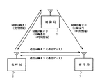
従来、スペクトル拡散方式を用いた通信システムにおいては、図8に示すように、制御局4と、発呼局5と、着呼局6とから構成されており、発呼局5と着呼局6との間は図9に示すような接続手順で接続されている。
【0003】
ここで、発呼局5の送信部は、図10(a)に示すように、変調器43を備えており、変調器43は発呼局5に接続される端末41からの送信要求入力時に、同期信号を送出後、端末41からの通話データに対し、回線番号(#2)の設定に応じて拡散コード発生器44から発生される拡散コードに基づいて変調をかけ、その信号を通話回線#2に送信する。
【0004】
また、発呼局5の受信部は、図10(b)に示すように、復調器47と初期同期回路48とを備えており、復調器47は初期同期回路48での同期制御に基づいて通話回線#3からの信号を復調し、通話データを発呼局5に接続される端末45に送出する。
【0005】
その際、復調器47は回線番号(#3)の設定に応じて拡散コード発生器50から発生される拡散コードに基づいて復調を行う。初期同期回路48は回線設定フラグがオンになった時の電力制御部49からの電力制御に応じて同期制御を行う。尚、図示していないが、着呼局6も発呼局5と同様の構成となっており、発呼局5と同様の動作を行う。
【0006】
これら図8〜図10を参照して従来の通信システムの動作について説明する。まず、発呼局5から上り制御回線#1を介して発呼を受けた制御局4は下り制御回線#0に発呼局5及び着呼局6の通話回線に割当てる回線番号(#2,#3)を一斉放送する。発呼局5及び着呼局6は下り制御回線#0を受信して回線番号を検出すると、送信部42及び受信部46の回線番号を割当てる。
【0007】
回線番号が割当てられた発呼局5及び着呼局6は図示せぬ回線制御部から回線設定フラグを受取り、送信部42は送信要求に基づいて通話回線#2,#3に通話データを送出する。
【0008】
受信部46の初期同期回路48は通話回線#2,#3の受信準備(待ち受け)のため、回線制御部からの回線設定フラグに基づいて電力制御を行う電力制御部49の制御信号に基づいて初期同期処理を開始する。この初期同期回路48による初期同期の確立後に発呼局5と着呼局6との間の通話が始まる。発呼局5と着呼局6との間の通話開始後に同期が外れた場合、再同期を行う。
【0009】
【発明が解決しようとする課題】
しかしながら、従来の通信システムでは、受信部の初期同期回路で、回線番号(拡散コード)の一致を検出するために拡散コードのチップ数に応じたフリップフロップ数が集積された整合フィルタが用いられているので、通話回線において、図11に示すように、初期同期処理を行う受信部の消費電力が大きくなるという問題がある。また、入力信号が無い期間に同期処理を行う場合には、ノイズや多重信号による誤同期の発生も問題となる。
【0010】
そこで、本発明の目的は上記の問題点を解消し、待ち受け時間の消費電力の軽減を図ることができ、誤同期の発生を防止することができる通信システム及びそれに用いる消費電力節電方法を提供することにある。
【0011】
【課題を解決するための手段】
本発明による通信システムは、発呼局から上り制御回線を介して着呼局への発呼を受付けた時に制御局が下り制御回線に前記発呼局及び前記着呼局の通話回線に割当てる回線番号を一斉放送し、前記発呼局及び前記着呼局でその回線番号を基に、前記通話回線の受信準備のための初期同期の確立後に前記発呼局と前記着呼局との通話を行う通信システムであって、
前記制御局は、前記発呼局から上り制御回線を介して着呼局への発呼を受付けた時に前記通話回線に割当てる回線番号と前記初期同期の動作開始を制限する時刻情報とを一斉放送する手段を備え、
前記発呼局及び前記着呼局は、前記時刻情報を基に前記初期同期の動作開始を制御する手段を備え、
前記初期同期の動作は、前記通話回線において前記時刻情報で示される時間以前の受信信号の無い期間と前記初期同期が確立した後とに停止するようにし、前記時刻情報が示す時間から前記初期同期が確立するまで行っている。
【0012】
本発明による通信システムの消費電力節電方法は、発呼局から上り制御回線を介して着呼局への発呼を受付けた時に制御局が下り制御回線に前記発呼局及び前記着呼局の通話回線に割当てる回線番号を一斉放送し、前記発呼局及び前記着呼局でその回線番号を基に、前記通話回線の受信準備のための初期同期の確立後に前記発呼局と前記着呼局との通話を行う通信システムの消費電力節電方法であって、
前記発呼局から上り制御回線を介して着呼局への発呼を受付けた時に前記通話回線に割当てる回線番号と前記初期同期の動作開始を制限する時刻情報とを前記制御局から一斉放送し、前記時刻情報を基に前記発呼局及び前記着呼局における前記初期同期の動作開始を制御するようにし、
前記初期同期の動作は、前記通話回線において前記時刻情報で示される時間以前の受信信号の無い期間と前記初期同期が確立した後とに停止するようにし、前記時刻情報が示す時間から前記初期同期が確立するまで行っている。
【0013】
すなわち、本発明の通信システムは、発呼局から発呼を受けた制御局が下り制御回線を介して発呼局及び着呼局の通話回線に割り当てる回線番号と時刻情報とを一斉放送し、下り制御回線を受信して回線番号を検出した発呼局及び着呼局で送信部及び受信部の回線番号を割当て、送信部で送信要求と時刻情報とに基づいて通話回線に通話データを送出するとともに、受信部で通話回線の受信準備のため、時刻情報から得られる電力制御部の制御信号に基づいて初期同期処理を開始する。
【0014】
これによって、入力信号が無い期間に初期同期処理が行われないので、消費電力の低減を図ることが可能になるとともに、入力信号が無い期間のノイズや多重信号による誤同期の発生を防止することが可能となる。
【0015】
【発明の実施の形態】
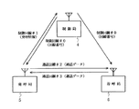
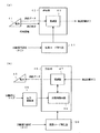
次に、本発明の一実施例について図面を参照して説明する。図1は本発明の一実施例による通信システムの構成を示すブロック図である。図1において、本発明の一実施例による通信システムは制御局1と、発呼局2と、着呼局3とから構成されている。
【0016】
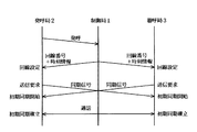
図2は本発明の一実施例による通信システムの接続手順を示すシーケンスチャートである。これら図1及び図2を参照して本発明の一実施例による通信システムの接続手順について説明する。
【0017】
制御局1は発呼局2から上り制御回線#1を介して発呼情報を受信すると、下り制御回線#0に発呼局2及び着呼局3の通話回線に割り当てる回線番号(#2,#3)と受信開始を示す時刻情報とを一斉放送する。
【0018】
発呼局2及び着呼局3は下り制御回線#0を受信して回線番号を検出すると、送信部及び受信部の回線番号(#2,#3)を割当てる。回線番号が割当てられた発呼局2及び着呼局3では送信部が送信要求と時刻情報とに基づいて通話回線#2,#3に通話データを送出する。
【0019】
また、発呼局2及び着呼局3各々の受信部は通話回線#2,#3の受信準備(待ち受け)のため、時刻情報から得られる電力制御部の制御信号に基づいて初期同期処理を開始する。この場合、初期同期処理は時刻情報以前の受信信号の無い期間及び初期同期が確立した後、停止する。これによって、発呼局2と着呼局3との通話が開始される。
【0020】
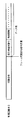
図3は図1の下り制御回線#0のフレーム信号の構成を示す図である。図3において、下り制御回線#0のフレーム信号は同期信号と、相手先端末番号及び時刻情報を含むデータ部とから構成され、定期的に同期信号が含まれる連続波である。
【0021】
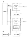
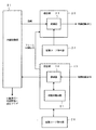
図4は図1の制御局1の制御回線送受信部の構成を示すブロック図である。図4において、制御局1の制御回線送受信部は回線制御部11と、送信部12と、拡散コード発生器14,18と、受信部15と、基準時刻発生器19とから構成されており、送信部12は変調器13を、受信部15は復調器16及び初期同期回路17をそれぞれ備えている。
【0022】
回線制御部11は受信部15の復調器16が拡散コード発生器18で発生される拡散コードを基に上り制御回線#1からの発呼情報を復調して出力してくると、回線番号及び時刻情報を送信部12の変調器13で変調して下り制御回線#0に送信する。
【0023】
ここで、送信部12及び受信部15は基準時刻発生器19からのクロック信号を基に動作し、送信部12の変調器13は拡散コード発生器14で発生される拡散コードを基に下り制御回線#0への送信信号を変調する。
【0024】
図5は図1の発呼局2及び着呼局3各々の制御回線送受信部の構成を示すブロック図である。図5において、発呼局2及び着呼局3各々の制御回線送受信部は回線制御部21と、送信部22と、拡散コード発生器24,28と、受信部25とから構成されており、送信部22は変調器23を、受信部25は復調器26及び初期同期回路27をそれぞれ備えている。
【0025】
回線制御部21は図示せぬ端末から発呼が指示されると、その発呼情報を送信部22の変調器23で変調して上り制御回線#1に送信する。また、回線制御部21は受信部25の復調器26が拡散コード発生器28で発生される拡散コードを基に下り制御回線#0からの回線番号及び時刻情報を復調して出力してくると、回線番号と時刻情報と設定フラグとを図示せぬ通話回線送受信部に出力する。
【0026】
ここで、送信部22は受信部25で検出されたフレーム同期信号を基に動作し、送信部22の変調器23は拡散コード発生器24で発生される拡散コードを基に上り制御回線#1への信号を変調する。
【0027】
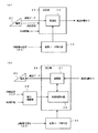
図6(a)は図1の発呼局2の通話回線送信部の構成を示すブロック図であり、図6(b)は図1の発呼局2の通話回線受信部の構成を示すブロック図である。図6(a)において、発呼局2の通話回線送信部は変調器33を備えた送信部32と、回線番号設定(#2)に応じた拡散コードを発生する拡散コード発生器34とを含んで構成され、送信部32は発呼局2の外部また内部に配設された端末31と通話回線#2とにそれぞれ接続されている。
【0028】
図6(b)において、発呼局2の通話回線受信部は復調器37及び初期同期回路38を備えた受信部36と、回線設定フラグ及び時刻情報を基に初期同期回路38に対する電力制御を行う電力制御部39と、回線番号設定(#3)に応じた拡散コードを発生する拡散コード発生器40とを含んで構成され、受信部36は発呼局2の外部また内部に配設された端末35と通話回線#3とにそれぞれ接続されている。尚、図示していないが、着呼局3の通話回線送信部及び通話回線受信部の構成は上記の発呼局2の構成及び動作と同様である。
【0029】
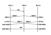
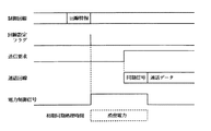
図7は図1の発呼局2及び着呼局3の送受信部の動作を示すタイミングチャートである。これら図1〜図7を参照して本発明の一実施例による通信システムの処理動作について説明する。
【0030】
制御局1は発呼局2から上り制御回線#1を介して発呼情報を受信すると、下り制御回線#0に発呼局2及び着呼局3の通話回線に割当てる回線番号(#2,#3)と時刻情報[受信開始を示す時間(例えば、現在の時刻からx秒後)]とを一斉放送する。この場合、時刻情報は発呼局2及び着呼局3の受信部37の初期同期回路38における初期同期動作開始を制限する信号である。
【0031】
発呼局2及び着呼局3は下り制御回線#0を受信して回線番号を検出し、その検出結果を基に送信部32及び受信部36の回線番号を割当てる。この時、発呼局2及び着呼局3は下り制御回線#0の同期が完了してから、回線設定情報を制御局1から受信する。また、下り制御回線#0のフレーム信号は定期的に同期信号が含まれる連続波であり、従来通り、一度初期捕捉が終ると、トラッキングで同期保持が行われる。
【0032】
回線番号が割当てられた発呼局2及び着呼局3は回線制御部21から回線設定フラグを受取ると、送信部32が送信要求と時刻情報とに基づいて通話回線#2,#3に通話データを送出する。また、受信部36は通話回線#2,#3の受信準備(待ち受け)のため、時刻情報から得られる電力制御部39の制御信号に基づいて初期同期回路38での初期同期処理を開始する。
【0033】
この初期同期回路38での初期同期処理は通話回線において時刻情報以前の受信信号の無い期間停止しており、初期同期が確立した後に停止するようになっている。つまり、初期同期回路38での初期同期処理は時刻情報が示す時間から初期同期が確立するまで行われることとなる。
【0034】
この後、発呼局2と着呼局3との間で、通話回線#2,#3を通して通話が開始される。但し、通話が開始された後に同期が外れた場合には再同期が行われることとなる。
【0035】
ここで、時刻情報は図4に示す制御局1の制御回線送受信部及び図5に示す発呼局2及び着呼局3各々の制御回線送受信部において、下り制御回線#0に通知される設定値や下り制御回線#0のフレーム同期信号から抽出するタイミング信号を基に得ることができる。
【0036】
また、通話回線の同期プリアンブルは1回だけなので、相手局が受信状態になる前に送信することはできない(送信を少し遅延させる必要がある)。また、回線設定フラグから送信要求までに長い時間がかかるのはポーリング時間やタイマ待ち時間等の理由によるものである。
【0037】
上記の構成において、消費電力の節電は数ワット×数秒程度の単位である。また、はじめに着呼側で送信要求があり、着信応答を受けた発呼側が次に送信要求を行う。送信要求タイミングは上記のような順序があるので、同時刻とは限らない。
【0038】
このように、発呼局2からの発呼情報に対して制御局1から回線番号と時刻情報とを下り制御回線#0に送信し、発呼局2及び着呼局3での初期同期処理を回線設定フラグと時刻情報とに基づいて行うことによって、入力信号が無い期間に初期同期処理が行われないので、消費電力の低減を図ることができるとともに、入力信号が無い期間のノイズや多重信号による誤同期の発生を防止することができる。
【0039】
【発明の効果】
以上説明したように本発明によれば、発呼局から上り制御回線を介して着呼局への発呼を受付けた時に制御局が下り制御回線に発呼局及び着呼局の通話回線に割当てる回線番号を一斉放送し、発呼局及び着呼局でその回線番号を基に、通話回線の受信準備のための初期同期の確立後に発呼局と着呼局との通話を行う通信システムにおいて、発呼局から上り制御回線を介して着呼局への発呼を受付けた時に通話回線に割当てる回線番号と初期同期の動作開始を制限する時刻情報とを制御局から一斉放送し、その時刻情報を基に発呼局及び着呼局における初期同期の動作開始を制御することによって、待ち受け時間の消費電力の軽減を図ることができ、誤同期の発生を防止することができるという効果がある。
【図面の簡単な説明】
【図1】本発明の一実施例による通信システムの構成を示すブロック図である。
【図2】本発明の一実施例による通信システムの接続手順を示すシーケンスチャートである。
【図3】図1の下り制御回線#0のフレーム信号の構成を示す図である。
【図4】図1の制御局の制御回線送受信部の構成を示すブロック図である。
【図5】図1の発呼局及び着呼局各々の制御回線送受信部の構成を示すブロック図である。
【図6】(a)は図1の発呼局の通話回線送信部の構成を示すブロック図、図6(b)は図1の発呼局の通話回線受信部の構成を示すブロック図である。
【図7】図1の発呼局及び着呼局の送受信部の動作を示すタイミングチャートである。
【図8】従来例による通信システムの構成を示すブロック図である。
【図9】従来例による通信システムの接続手順を示すシーケンスチャートである。
【図10】(a)は図8の発呼局の通話回線送信部の構成を示すブロック図、(b)は図8の発呼局の通話回線受信部の構成を示すブロック図である。
【図11】図8の発呼局及び着呼局の送受信部の動作を示すタイミングチャートである。
【符号の説明】
1 制御局
2 発呼局
3 着呼局
11,21 回線制御部
12,22,32 送信部
13,23,33 変調器
14,18,24,38,
34,40 拡散コード発生器
15,25,36 受信部
16,26,37 復調器
17,27,38 初期同期回路
19 基準時刻発生器
31,35 端末
39 電力制御部
#0 下り制御回線
#1 上り制御回線
#2,#3 通話回線[0001]
BACKGROUND OF THE INVENTION
The present invention relates to a communication system and a power saving method used therefor, and more particularly to a satellite communication system using a spread spectrum system.
[0002]
[Prior art]
Conventionally, in a communication system using a spread spectrum system, as shown in FIG. 8, a
[0003]
Here, the transmission unit of the
[0004]
Further, as shown in FIG. 10B, the receiving unit of the
[0005]
At that time, the
[0006]
The operation of the conventional communication system will be described with reference to FIGS. First, the
[0007]
The
[0008]
The
[0009]
[Problems to be solved by the invention]
However, in the conventional communication system, a matching filter in which the number of flip-flops corresponding to the number of chips of the spread code is integrated is used in the initial synchronization circuit of the receiving unit in order to detect the coincidence of the line number (spread code). Therefore, in the telephone line, as shown in FIG. 11, there is a problem that the power consumption of the receiving unit that performs the initial synchronization processing increases. In addition, when synchronization processing is performed during a period when there is no input signal, the occurrence of erroneous synchronization due to noise or multiple signals becomes a problem.
[0010]
SUMMARY OF THE INVENTION Accordingly, an object of the present invention is to provide a communication system capable of solving the above-described problems, reducing power consumption during standby time, and preventing occurrence of false synchronization, and a power consumption power saving method used therefor. There is.
[0011]
[Means for Solving the Problems]
In the communication system according to the present invention, when a call from the calling station to the called station is accepted via the uplink control line, the control station assigns the downlink control line to the calling station and the call line of the called station. Broadcast the number, and based on the line number at the calling station and the called station, call between the calling station and the called station after establishing the initial synchronization for the reception preparation of the call line A communication system to perform,
The control station broadcasts a line number assigned to the call line when the call is received from the calling station via the uplink control line to the call line and time information for restricting the start of the initial synchronization operation. Means to
The calling station and the called station comprise means for controlling the operation start of the initial synchronization based on the time information ,
The operation of the initial synchronization is stopped in a period in which there is no reception signal before the time indicated by the time information on the telephone line and after the initial synchronization is established, and the initial synchronization is started from the time indicated by the time information. Is going until established .
[0012]
According to the power saving method of the communication system according to the present invention, when the call is received from the calling station to the called station via the uplink control line, the control station transmits the call station and the called station to the downlink control line. Broadcasting a line number to be assigned to a call line at the same time, and based on the line number at the calling station and the called station, after establishing initial synchronization for preparation for reception of the call line, the calling station and the incoming call A power consumption saving method of a communication system for making a call with a station,
When the call from the calling station to the called station via the uplink control line is received, the control station broadcasts the line number assigned to the call line and the time information for restricting the start of the initial synchronization operation. , Based on the time information, to control the operation of the initial synchronization in the calling station and the called station ,
The operation of the initial synchronization is stopped in a period in which there is no reception signal before the time indicated by the time information on the telephone line and after the initial synchronization is established, and the initial synchronization is started from the time indicated by the time information. Is going until established .
[0013]
That is, the communication system of the present invention broadcasts the line number and time information allotted to the calling line of the calling station and the called station via the downlink control line by the control station that receives the call from the calling station, The line number of the transmission unit and the reception unit is assigned at the calling station and the receiving station that have received the downlink control line and the line number is detected, and the transmission unit sends the call data to the communication line based on the transmission request and time information. At the same time, an initial synchronization process is started based on the control signal of the power control unit obtained from the time information in order to prepare the reception unit for receiving the communication line.
[0014]
As a result, since initial synchronization processing is not performed during a period when there is no input signal, it is possible to reduce power consumption and prevent occurrence of false synchronization due to noise during a period when there is no input signal or multiple signals. Is possible.
[0015]
DETAILED DESCRIPTION OF THE INVENTION
Next, an embodiment of the present invention will be described with reference to the drawings. FIG. 1 is a block diagram showing a configuration of a communication system according to an embodiment of the present invention. In FIG. 1, a communication system according to an embodiment of the present invention includes a
[0016]
FIG. 2 is a sequence chart showing a connection procedure of the communication system according to the embodiment of the present invention. A connection procedure of a communication system according to an embodiment of the present invention will be described with reference to FIGS.
[0017]
When the
[0018]
When the calling
[0019]
In addition, the receiving units of the calling
[0020]
FIG. 3 is a diagram showing a frame signal configuration of the downlink control line # 0 of FIG. In FIG. 3, the frame signal of the downlink control line # 0 is a continuous wave composed of a synchronization signal and a data part including a counterpart terminal number and time information, and periodically including the synchronization signal.
[0021]
FIG. 4 is a block diagram showing the configuration of the control line transmitting / receiving unit of the
[0022]
When the demodulator 16 of the receiving
[0023]
Here, the
[0024]
FIG. 5 is a block diagram showing the configuration of the control line transmitting / receiving unit of each of the calling
[0025]
When a call is instructed from a terminal (not shown), the
[0026]
Here, the
[0027]
6A is a block diagram showing the configuration of the communication line transmission unit of the calling
[0028]
In FIG. 6 (b), the call line receiving unit of the calling
[0029]
FIG. 7 is a timing chart showing the operation of the transmitting / receiving units of the calling
[0030]
When the
[0031]
The calling
[0032]
When the calling
[0033]
The initial synchronization processing in the
[0034]
Thereafter, a call is started between the calling
[0035]
Here, the time information is set in the control line transmission / reception unit of the
[0036]
Further, since the synchronization preamble of the telephone line is only once, it cannot be transmitted before the other station enters the reception state (transmission needs to be delayed a little). In addition, the long time required from the line setting flag to the transmission request is due to reasons such as polling time and timer waiting time.
[0037]
In the above configuration, power saving is in units of several watts × several seconds. First, there is a transmission request on the called side, and the calling side that has received the incoming call response then makes a transmission request. Since the transmission request timing is in the order as described above, it is not always the same time.
[0038]
In this way, the line number and time information are transmitted from the
[0039]
【The invention's effect】
As described above, according to the present invention, when a call is received from the calling station to the called station via the uplink control line, the control station sets the downlink control line to the calling station and the call line of the called station. A communication system that broadcasts allotted line numbers at the same time, and makes a call between the calling station and the called station after the establishment of initial synchronization for preparation for receiving the call line based on the line numbers at the calling station and the called station , The control station broadcasts the line number assigned to the call line when the call is received from the calling station via the uplink control line and the time information for restricting the start of the initial synchronization operation. By controlling the start of the initial synchronization operation at the calling station and the called station based on the time information, it is possible to reduce the power consumption of the standby time and to prevent the occurrence of erroneous synchronization. is there.
[Brief description of the drawings]
FIG. 1 is a block diagram showing a configuration of a communication system according to an embodiment of the present invention.
FIG. 2 is a sequence chart showing a connection procedure of a communication system according to an embodiment of the present invention.
FIG. 3 is a diagram showing a configuration of a frame signal of downlink control line # 0 in FIG. 1;
4 is a block diagram showing a configuration of a control line transmission / reception unit of the control station in FIG. 1. FIG.
5 is a block diagram showing a configuration of a control line transmission / reception unit of each of the calling station and the called station of FIG.
6A is a block diagram illustrating a configuration of a call line transmission unit of the calling station in FIG. 1, and FIG. 6B is a block diagram illustrating a configuration of a call line reception unit of the calling station in FIG. is there.
7 is a timing chart showing the operation of the transmitting / receiving units of the calling station and the called station in FIG. 1. FIG.
FIG. 8 is a block diagram showing a configuration of a communication system according to a conventional example.
FIG. 9 is a sequence chart showing a connection procedure of a communication system according to a conventional example.
10A is a block diagram illustrating a configuration of a call line transmission unit of the calling station in FIG. 8, and FIG. 10B is a block diagram illustrating a configuration of a call line reception unit of the calling station in FIG. 8;
11 is a timing chart showing the operation of the transmitting and receiving units of the calling station and the called station in FIG. 8. FIG.
[Explanation of symbols]
DESCRIPTION OF
34, 40 Spreading
Claims (6)
前記制御局は、前記発呼局から上り制御回線を介して着呼局への発呼を受付けた時に前記通話回線に割当てる回線番号と前記初期同期の動作開始を制限する時刻情報とを一斉放送する手段を有し、
前記発呼局及び前記着呼局は、前記時刻情報を基に前記初期同期の動作開始を制御する手段を有し、
前記初期同期の動作は、前記通話回線において前記時刻情報で示される時間以前の受信信号の無い期間と前記初期同期が確立した後とに停止するようにし、前記時刻情報が示す時間から前記初期同期が確立するまで行うことを特徴とする通信システム。When the call from the calling station to the called station via the uplink control line is accepted, the control station broadcasts the line number assigned to the calling station and the call line of the called station to the downlink control line, and A communication system for performing a call between the calling station and the called station after establishing initial synchronization for preparation for receiving the call line based on the line number at the calling station and the called station,
The control station broadcasts a line number assigned to the call line and time information for restricting the start of the initial synchronization operation when a call from the calling station to the called station is received via an uplink control line. Means to
The calling station and the called station, have a means for controlling the initial synchronization operation is started based on the time information,
The operation of the initial synchronization is stopped in a period in which there is no reception signal before the time indicated by the time information on the telephone line and after the initial synchronization is established, and the initial synchronization is started from the time indicated by the time information. A communication system characterized in that the communication is performed until it is established .
前記発呼局から上り制御回線を介して着呼局への発呼を受付けた時に前記通話回線に割当てる回線番号と前記初期同期の動作開始を制限する時刻情報とを前記制御局から一斉放送し、前記時刻情報を基に前記発呼局及び前記着呼局における前記初期同期の動作開始を制御するようにし、When the call from the calling station to the called station via the uplink control line is received, the control station broadcasts the line number assigned to the call line and the time information for restricting the start of the initial synchronization operation. , Based on the time information, to control the operation of the initial synchronization in the calling station and the called station,
前記初期同期の動作は、前記通話回線において前記時刻情報で示される時間以前の受信信号の無い期間と前記初期同期が確立した後とに停止するようにし、前記時刻情報が示す時間から前記初期同期が確立するまで行うことを特徴とする消費電力節電方法。The operation of the initial synchronization is stopped in a period in which there is no reception signal before the time indicated by the time information on the telephone line and after the initial synchronization is established, and the initial synchronization is started from the time indicated by the time information. Power consumption power saving method characterized by performing until it establishes.
Priority Applications (1)
| Application Number | Priority Date | Filing Date | Title |
|---|---|---|---|
| JP2000126835A JP4394251B2 (en) | 2000-04-27 | 2000-04-27 | Communication system and power consumption saving method used therefor |
Applications Claiming Priority (1)
| Application Number | Priority Date | Filing Date | Title |
|---|---|---|---|
| JP2000126835A JP4394251B2 (en) | 2000-04-27 | 2000-04-27 | Communication system and power consumption saving method used therefor |
Publications (2)
| Publication Number | Publication Date |
|---|---|
| JP2001308777A JP2001308777A (en) | 2001-11-02 |
| JP4394251B2 true JP4394251B2 (en) | 2010-01-06 |
Family
ID=18636529
Family Applications (1)
| Application Number | Title | Priority Date | Filing Date |
|---|---|---|---|
| JP2000126835A Expired - Fee Related JP4394251B2 (en) | 2000-04-27 | 2000-04-27 | Communication system and power consumption saving method used therefor |
Country Status (1)
| Country | Link |
|---|---|
| JP (1) | JP4394251B2 (en) |
Families Citing this family (2)
| Publication number | Priority date | Publication date | Assignee | Title |
|---|---|---|---|---|
| US20110038290A1 (en) * | 2009-08-11 | 2011-02-17 | Michelle Xiaohong Gong | Device, system and method of power management in a wireless area network |
| WO2015058407A1 (en) | 2013-10-25 | 2015-04-30 | 华为终端有限公司 | Method and device for device-to-device (d2d) communication |
-
2000
- 2000-04-27 JP JP2000126835A patent/JP4394251B2/en not_active Expired - Fee Related
Also Published As
| Publication number | Publication date |
|---|---|
| JP2001308777A (en) | 2001-11-02 |
Similar Documents
| Publication | Publication Date | Title |
|---|---|---|
| US5748621A (en) | Digital mobile communication system | |
| KR950013309B1 (en) | How to reduce power consumption in a communication unit | |
| KR0150354B1 (en) | Method and apparatus for direct communication in a tdma radio communication system | |
| JPH0418491B2 (en) | ||
| JP3172937B2 (en) | Frame synchronization method between mobile stations | |
| JP4394251B2 (en) | Communication system and power consumption saving method used therefor | |
| US6275700B1 (en) | Incoming cell control method and device for mobile communication device | |
| JPH0555975A (en) | Satellite multiple address communication system and equipment therefor | |
| JP2658879B2 (en) | MONITORING METHOD, MONITORING METHOD, AND TERMINAL OF MULTI-DIRECTIONAL MULTIPLE COMMUNICATION SYSTEM | |
| JPH05308334A (en) | Frame synchronization system of tdma system radio base station | |
| JP3332554B2 (en) | Wireless communication system | |
| JPH07212838A (en) | Digital cordless telephone device | |
| JPH06350595A (en) | How to change scramble code during communication | |
| JP3037324B1 (en) | Radio selective call receiver | |
| JP2806424B2 (en) | Battery saving terminal | |
| JP2611652B2 (en) | Multi-way multiplex communication system | |
| JP2844982B2 (en) | Wireless relay system for time division multiplex communication system | |
| JP2690405B2 (en) | Digital transceiver | |
| JP2616477B2 (en) | Multi-way multiplex communication system | |
| JPH0823319A (en) | Synchronous control method | |
| JP2784901B2 (en) | Communication method in spread spectrum / demand assignment multiple access system and communication device used for the same | |
| JPS61242464A (en) | Facsimile signal transmitting system | |
| JP2817431B2 (en) | Satellite communication earth station equipment | |
| JP3435012B2 (en) | Wireless communication system | |
| JPH09148977A (en) | Wireless communication system |
Legal Events
| Date | Code | Title | Description |
|---|---|---|---|
| A621 | Written request for application examination |
Free format text: JAPANESE INTERMEDIATE CODE: A621 Effective date: 20070308 |
|
| A977 | Report on retrieval |
Free format text: JAPANESE INTERMEDIATE CODE: A971007 Effective date: 20090701 |
|
| A131 | Notification of reasons for refusal |
Free format text: JAPANESE INTERMEDIATE CODE: A131 Effective date: 20090707 |
|
| A521 | Request for written amendment filed |
Free format text: JAPANESE INTERMEDIATE CODE: A523 Effective date: 20090831 |
|
| TRDD | Decision of grant or rejection written | ||
| A01 | Written decision to grant a patent or to grant a registration (utility model) |
Free format text: JAPANESE INTERMEDIATE CODE: A01 Effective date: 20091006 |
|
| A01 | Written decision to grant a patent or to grant a registration (utility model) |
Free format text: JAPANESE INTERMEDIATE CODE: A01 |
|
| A61 | First payment of annual fees (during grant procedure) |
Free format text: JAPANESE INTERMEDIATE CODE: A61 Effective date: 20091015 |
|
| R150 | Certificate of patent or registration of utility model |
Free format text: JAPANESE INTERMEDIATE CODE: R150 |
|
| FPAY | Renewal fee payment (event date is renewal date of database) |
Free format text: PAYMENT UNTIL: 20121023 Year of fee payment: 3 |
|
| FPAY | Renewal fee payment (event date is renewal date of database) |
Free format text: PAYMENT UNTIL: 20131023 Year of fee payment: 4 |
|
| LAPS | Cancellation because of no payment of annual fees |