JP4393189B2 - Rod-shaped tool for cutting workpieces - Google Patents
Rod-shaped tool for cutting workpieces Download PDFInfo
- Publication number
- JP4393189B2 JP4393189B2 JP2003524758A JP2003524758A JP4393189B2 JP 4393189 B2 JP4393189 B2 JP 4393189B2 JP 2003524758 A JP2003524758 A JP 2003524758A JP 2003524758 A JP2003524758 A JP 2003524758A JP 4393189 B2 JP4393189 B2 JP 4393189B2
- Authority
- JP
- Japan
- Prior art keywords
- range
- shank
- rod
- blade groove
- center axis
- Prior art date
- Legal status (The legal status is an assumption and is not a legal conclusion. Google has not performed a legal analysis and makes no representation as to the accuracy of the status listed.)
- Expired - Lifetime
Links
Images


Classifications
-
- B—PERFORMING OPERATIONS; TRANSPORTING
- B23—MACHINE TOOLS; METAL-WORKING NOT OTHERWISE PROVIDED FOR
- B23B—TURNING; BORING
- B23B31/00—Chucks; Expansion mandrels; Adaptations thereof for remote control
- B23B31/005—Cylindrical shanks of tools
-
- B—PERFORMING OPERATIONS; TRANSPORTING
- B23—MACHINE TOOLS; METAL-WORKING NOT OTHERWISE PROVIDED FOR
- B23B—TURNING; BORING
- B23B51/00—Tools for drilling machines
- B23B51/06—Drills with lubricating or cooling equipment
-
- B—PERFORMING OPERATIONS; TRANSPORTING
- B23—MACHINE TOOLS; METAL-WORKING NOT OTHERWISE PROVIDED FOR
- B23B—TURNING; BORING
- B23B2222/00—Materials of tools or workpieces composed of metals, alloys or metal matrices
- B23B2222/28—Details of hard metal, i.e. cemented carbide
-
- B—PERFORMING OPERATIONS; TRANSPORTING
- B23—MACHINE TOOLS; METAL-WORKING NOT OTHERWISE PROVIDED FOR
- B23B—TURNING; BORING
- B23B2226/00—Materials of tools or workpieces not comprising a metal
- B23B2226/18—Ceramic
-
- B—PERFORMING OPERATIONS; TRANSPORTING
- B23—MACHINE TOOLS; METAL-WORKING NOT OTHERWISE PROVIDED FOR
- B23B—TURNING; BORING
- B23B2231/00—Details of chucks, toolholder shanks or tool shanks
- B23B2231/02—Features of shanks of tools not relating to the operation performed by the tool
- B23B2231/0208—Bores
-
- B—PERFORMING OPERATIONS; TRANSPORTING
- B23—MACHINE TOOLS; METAL-WORKING NOT OTHERWISE PROVIDED FOR
- B23B—TURNING; BORING
- B23B2231/00—Details of chucks, toolholder shanks or tool shanks
- B23B2231/02—Features of shanks of tools not relating to the operation performed by the tool
- B23B2231/0216—Overall cross sectional shape of the shank
- B23B2231/0232—Hexagonal
-
- B—PERFORMING OPERATIONS; TRANSPORTING
- B23—MACHINE TOOLS; METAL-WORKING NOT OTHERWISE PROVIDED FOR
- B23B—TURNING; BORING
- B23B2231/00—Details of chucks, toolholder shanks or tool shanks
- B23B2231/02—Features of shanks of tools not relating to the operation performed by the tool
- B23B2231/026—Grooves
- B23B2231/0264—Axial grooves
-
- B—PERFORMING OPERATIONS; TRANSPORTING
- B23—MACHINE TOOLS; METAL-WORKING NOT OTHERWISE PROVIDED FOR
- B23B—TURNING; BORING
- B23B2231/00—Details of chucks, toolholder shanks or tool shanks
- B23B2231/02—Features of shanks of tools not relating to the operation performed by the tool
- B23B2231/028—Lugs
-
- Y—GENERAL TAGGING OF NEW TECHNOLOGICAL DEVELOPMENTS; GENERAL TAGGING OF CROSS-SECTIONAL TECHNOLOGIES SPANNING OVER SEVERAL SECTIONS OF THE IPC; TECHNICAL SUBJECTS COVERED BY FORMER USPC CROSS-REFERENCE ART COLLECTIONS [XRACs] AND DIGESTS
- Y10—TECHNICAL SUBJECTS COVERED BY FORMER USPC
- Y10T—TECHNICAL SUBJECTS COVERED BY FORMER US CLASSIFICATION
- Y10T408/00—Cutting by use of rotating axially moving tool
- Y10T408/44—Cutting by use of rotating axially moving tool with means to apply transient, fluent medium to work or product
- Y10T408/45—Cutting by use of rotating axially moving tool with means to apply transient, fluent medium to work or product including Tool with duct
- Y10T408/455—Conducting channel extending to end of Tool
-
- Y—GENERAL TAGGING OF NEW TECHNOLOGICAL DEVELOPMENTS; GENERAL TAGGING OF CROSS-SECTIONAL TECHNOLOGIES SPANNING OVER SEVERAL SECTIONS OF THE IPC; TECHNICAL SUBJECTS COVERED BY FORMER USPC CROSS-REFERENCE ART COLLECTIONS [XRACs] AND DIGESTS
- Y10—TECHNICAL SUBJECTS COVERED BY FORMER USPC
- Y10T—TECHNICAL SUBJECTS COVERED BY FORMER US CLASSIFICATION
- Y10T408/00—Cutting by use of rotating axially moving tool
- Y10T408/89—Tool or Tool with support
- Y10T408/907—Tool or Tool with support including detailed shank
Abstract
Description
本発明は、焼結された材料から成る、ワークを切削加工するためのロッド状の工具、たとえばドリルロッド、フライスロッドまたはリーマロッドであって、ロッド中心軸線と、シャンク範囲と、ロッド中心軸線の方向でシャンク範囲に隣接した刃溝範囲とが設けられており、当該工具が、刃溝範囲に、ロッド中心軸線を巡って延びる外側の少なくとも1つの刃溝を有していて、シャンク範囲に刃溝を有しておらず、該刃溝が、ロッド中心軸線から最小間隔を有している形式のものに関する。 The present invention relates to a rod-shaped tool for machining a workpiece, such as a drill rod, milling rod or reamer rod, made of a sintered material, the rod center axis, the shank range, and the direction of the rod center axis And the tool has a groove area adjacent to the shank area, and the tool has at least one outer groove extending around the center axis of the rod in the groove area, and has a blade groove in the shank area. And the blade groove has a minimum distance from the rod center axis.
このような工具は一般的に知られている。市販のあらゆる金属ドリルはこのように形成されている。 Such tools are generally known. All commercially available metal drills are thus formed.
さらに、ドイツ連邦共和国特許出願公開第19942966号明細書に基づき、冒頭で述べた形式の工具に、偏心的に配置された通路を加工成形することが公知である。この通路は刃溝と一緒にロッド中心軸線を巡って螺旋状に延びていて、冷却媒体または潤滑媒体を工具先端部に供給するために働く。 Furthermore, it is known from German Patent Application Publication No. 19942966 to machine eccentrically arranged passages in a tool of the type mentioned at the outset. This passage, along with the blade groove, extends helically around the rod center axis and serves to supply a cooling or lubricating medium to the tool tip.
ドイツ連邦共和国特許出願公開第19522837号明細書に基づき、ワークを切削加工するためのロッド状の工具が公知である。この公知の工具は、ロッド中心軸線と、シャンク範囲と、ロッド中心軸線の方向でシャンク範囲に隣接した刃溝範囲とを有している。この刃溝範囲には、工具が、ほぼ軸方向に延びる外側の2つの刃溝を有していて、シャンク範囲にはこのような刃溝を有していない。この刃溝はロッド中心軸線から最小間隔を有している。 A rod-shaped tool for cutting a workpiece is known from German Offenlegungsschrift 19 522 837. This known tool has a rod center axis, a shank range, and a blade groove range adjacent to the shank range in the direction of the rod center axis. In this blade groove range, the tool has two outer blade grooves extending substantially in the axial direction, and the shank region does not have such a blade groove. The blade groove has a minimum distance from the rod center axis.
ドイツ連邦共和国実用新案第8002631号明細書に基づき、加工したい材料を破砕加工するためのロッド状の工具が公知である。この公知の工具は、ロッド中心軸線と、シャンク範囲と、ロッド中心軸線の方向でシャンク範囲に隣接した溝範囲とを有している。工具は溝範囲に外側の溝を有している。この溝はロッド中心軸線から最小間隔を有している。シャンク範囲に工具はこのような溝を有していない。さらに、工具は中心切欠きを有している。この中心切欠きはロッド中心軸線の方向でシャンク範囲を越えて溝範囲にまで延びていて、この溝範囲に円形と異なる形状の横断面を有していて、溝範囲にロッド中心軸線から最大間隔を有している。この最大間隔は少なくとも最小間隔と同じ大きさに設定されている。
英国特許第571403号明細書に基づき、ワークを切削加工するためのロッド状の工具が公知である。この公知の工具は、ロッド中心軸線と、シャンク範囲と、ロッド中心軸線の方向でシャンク範囲に隣接した刃溝範囲とを有している。この刃溝範囲に工具は、ロッド中心軸線を巡って延びる外側の少なくとも1つの刃溝を有していて、シャンク範囲には有していない。刃溝はロッド中心軸線から最小間隔を有している。工具は円形の中心切欠きを有している。この中心切欠きはロッド中心軸線の方向でシャンク範囲を越えて刃溝範囲にまで延びている。したがって、ロッド中心軸線からの中心切欠きの最大間隔は、刃溝がロッド中心軸線から有する最小間隔よりも小さく設定されている。
アメリカ合衆国特許第2903921号明細書に基づき、ワークを切削加工するためのロッド状の工具が公知である。この公知の工具は、ロッド中心軸線と、シャンク範囲と、ロッド中心軸線の方向でシャンク範囲に隣接した刃溝範囲とを有している。この場合、工具は刃溝範囲に、ロッド中心軸線を巡って延びる外側の2つの刃溝を有していて、シャンク範囲にはこのような刃溝を有していない。この場合、刃溝はロッド中心軸線から最小間隔を有している。工具は、ロッド中心軸線に対して対称的に配置された2つの切欠きを有している。両切欠きは互いに分離されていて、円形と異なる形状のそれぞれ1つの横断面を有していて、ロッド中心軸線から最大間隔を有している。この最大間隔はロッド中心軸線からの刃溝の最小間隔よりも大きく設定されている。
アメリカ合衆国特許第4826364号明細書から、ドイツ連邦共和国特許出願公開第19942966号明細書の開示内容と比較可能である開示内容を知ることができる。
A rod-shaped tool for crushing a material to be machined is known from the German utility model No. 8002631. This known tool has a rod center axis, a shank range, and a groove range adjacent to the shank range in the direction of the rod center axis. The tool has an outer groove in the groove area. This groove has a minimum spacing from the rod center axis. The tool does not have such a groove in the shank area. Furthermore, the tool has a central notch. This center notch extends in the direction of the rod center axis beyond the shank range to the groove range, and this groove range has a cross-section with a shape different from a circle, and the groove range has a maximum distance from the rod center axis. have. This maximum interval is set at least as large as the minimum interval.
A rod-shaped tool for cutting a workpiece is known based on British Patent No. 5714033. This known tool has a rod center axis, a shank range, and a blade groove range adjacent to the shank range in the direction of the rod center axis. In this blade groove range, the tool has at least one outer blade groove extending around the rod center axis and not in the shank region. The blade groove has a minimum spacing from the rod center axis. The tool has a circular center notch. This central notch extends beyond the shank range to the blade groove range in the direction of the rod center axis. Therefore, the maximum distance of the center notch from the rod center axis is set smaller than the minimum distance that the blade groove has from the rod center axis.
A rod-shaped tool for cutting a workpiece is known based on the specification of U.S. Pat. No. 2,903,921. This known tool has a rod center axis, a shank range, and a blade groove range adjacent to the shank range in the direction of the rod center axis. In this case, the tool has two outer groove grooves extending around the rod center axis in the blade groove area, and does not have such a blade groove in the shank area. In this case, the blade groove has a minimum distance from the rod center axis. The tool has two notches arranged symmetrically with respect to the rod center axis. Both notches are separated from each other, each having a cross section of a different shape from a circle, with a maximum spacing from the rod center axis. This maximum interval is set larger than the minimum interval of the blade groove from the rod center axis.
From U.S. Pat. No. 4,826,364, the disclosure content which is comparable with the disclosure content of German Patent Application Publication No. 19942966 is known.
本発明の課題は、冒頭で述べた形式の工具を改良して、工具が同じ性能のまま、減少させられた材料使用によって製作可能となるようにすることである。 It is an object of the present invention to improve a tool of the type mentioned at the outset so that the tool can be produced with reduced material usage while maintaining the same performance.
この課題は、当該工具が、ロッド中心軸線の領域で材料なしの閉鎖された中心切欠きを有しており、該中心切欠きが、ロッド中心軸線の方向でシャンク範囲を越えて刃溝範囲にまで延びていて、該刃溝範囲に円形と異なる形状の横断面を有していて、刃溝範囲にロッド中心軸線から最大間隔を有しており、該最大間隔が、少なくとも最小間隔と同じ大きさに設定されていることによって解決される。 The problem is that the tool has a closed center notch with no material in the region of the rod center axis, the center notch going beyond the shank range in the direction of the rod center axis and into the blade groove range. The blade groove region has a cross section having a shape different from a circle, the blade groove region has a maximum distance from the rod center axis, and the maximum space is at least as large as the minimum space. It is solved by being set to.
なぜならば、これによって、工具がシャンク範囲だけでなく刃溝範囲でも中実に形成されておらず、中空に形成されているからである。にもかかわらず、工具の十分な安定性および負荷耐性が付与されている。 This is because, by this, the tool is not formed solidly in the shank range but also in the blade groove range, and is formed hollow. Nevertheless, sufficient stability and load resistance of the tool is imparted.
最大間隔が、シャンク範囲で少なくとも最小間隔と同じ大きさに設定されていて、有利には最小間隔よりも大きくすら設定されていると、特に大きな材料節約が得られる。このことは、特にシャンク範囲が、シャンク外径を有しており、最大間隔が、少なくともシャンク外径の0.2倍に設定されている場合に完全に認められる。しかし、工具の性能を損なわないためには、最大間隔が、最大でシャンク外径の0.45倍に設定されていることが望ましい。 Particularly large material savings can be obtained if the maximum spacing is set at least as large as the minimum spacing in the shank range, and advantageously even larger than the minimum spacing. This is fully appreciated, especially when the shank range has a shank outer diameter and the maximum spacing is set at least 0.2 times the shank outer diameter. However, in order not to impair the performance of the tool, it is desirable that the maximum interval is set to 0.45 times the outer diameter of the shank at the maximum.
刃溝範囲に設けられた中心切欠きの横断面が、刃溝範囲の外側横断面に適合されており、これによって、刃溝範囲が、ほぼ至るところに不変の材料厚さを有していると、材料節約の最適化が得られる。 The cross-section of the central notch provided in the blade groove area is adapted to the outer cross-section of the blade groove area, so that the blade groove area has a constant material thickness almost everywhere. And material savings optimization.
刃溝範囲の部分区分に、ロッド中心軸線に対して偏心的に配置された、冷却媒体または潤滑媒体のための少なくとも1つの案内通路が延びていてよく、該案内通路が、中心切欠きに連通接続されている。 At least one guide passage for the cooling medium or the lubricating medium, which is arranged eccentric to the central axis of the rod, may extend in a partial section of the blade groove area, the guide passage communicating with the central notch It is connected.
中心切欠きはシャンク範囲に選択的に円形の横断面または円形と異なる形状の横断面を有していてよい。円形と異なる形状の横断面を有している事例では、横断面が、たとえば長円形、楕円形または多角形に形成されていてよいかもしくは少なくとも1つの切欠きまたは少なくとも1つの突出部を有していてよい。この場合、円形と異なる形状の横断面によって、中心切欠きに導入された連行体による特に良好な力伝達が可能となる。 The central notch may have a circular cross section selectively in the shank area or a cross section having a shape different from the circular shape. In the case of having a cross section of a shape different from a circle, the cross section may be formed, for example, in the shape of an ellipse, an ellipse or a polygon, or has at least one notch or at least one protrusion. It may be. In this case, particularly good force transmission by the entrained body introduced into the central notch is possible due to the cross section having a shape different from the circular shape.
シャンク範囲に設けられた中心切欠きが、刃溝範囲に近い方の部分区分に、シャンク範囲の、刃溝範囲と反対の側の端部よりも大きな横断面を有していると、工具が特に簡単に工具ホルダに緊締可能となる。このためには、中心切欠きがやや円錐形に延びていてよく、かつ/または刃溝範囲に近い方の部分区分でハンマヘッド状にまたは鳩尾状に形成されていてよい。 If the central notch provided in the shank area has a larger cross section in the partial section closer to the edge groove area than the end of the shank area opposite to the edge groove area, the tool In particular, the tool holder can be tightened easily. For this purpose, the central notch may extend somewhat conically and / or may be formed in a hammerhead or dovetail shape in the partial section closer to the blade groove area.
さらなる利点および詳細は、図面に関連した以下の実施例の説明から明らかとなる。 Further advantages and details will become apparent from the following description of embodiments with reference to the drawings.
図1には、たとえばワークを切削加工するためのロッド状の工具に対してドリルロッドが示してある。しかし、本発明は、ドリルロッドと異なる工具も含んでいる。たとえばフライスロッドおよびリーマロッドが挙げられる。 FIG. 1 shows a drill rod for a rod-shaped tool for cutting a workpiece, for example. However, the present invention also includes a tool different from the drill rod. Examples thereof include a milling rod and a reamer rod.
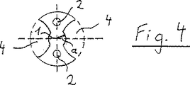
ドリルロッドは、たとえば鋼粉末から成る焼結された材料、硬質金属またはセラミックスから成っている。ドリルロッドを製作するためには、たとえばまずペースト状の焼結材料が押出し成形される。この押出し成形時には、ロッド中心軸線1に対して偏心的に複数の案内通路2がロッドに加工成形される。これらの案内通路2は、のちにドリルロッドを運転する場合に冷却媒体または潤滑媒体をドリル先端部3に供給するために働く。
The drill rod is made of sintered material, for example steel powder, hard metal or ceramics. In order to manufacture a drill rod, for example, a paste-like sintered material is first extruded. At the time of this extrusion molding, a plurality of
押出し成形の間または押出し成形の後、製作されたロッドがねじられる。したがって、案内通路2がロッド中心軸線1を巡って螺旋状に延びている。この場合、ねじりが、押出し成形されたロッドの定尺切断後に行われると有利である。
During or after extrusion, the manufactured rod is twisted. Therefore, the
さらに、焼結ロッドには、有利には焼結前に、しかし、いずれにせよ焼結材料の安定後、たとえば焼結材料の乾燥後または予備焼結後に、外側の刃溝4が加工成形される。この刃溝4もロッド中心軸線1を巡って螺旋状に延びている。
Furthermore, the
刃溝4は刃溝範囲5を規定している。刃溝4の、ドリル先端部3と反対の側の端部はシャンク範囲6への移行部を成している。このシャンク範囲6は刃溝4を有していない。シャンク範囲6は、ドリルロッドの、ドリル先端部3と反対の側の端部にまで延びている。すなわち、刃溝範囲5とシャンク範囲6とはロッド中心軸線1の方向で互いに直接隣接している。
The
シャンク範囲6はシャンク長さL1にわたって延びており、刃溝範囲5は刃部長さL2にわたって延びている。したがって、ドリルロッドは、シャンク長さL1と刃部長さL2との合計に相当する全長Lを有している。この全長Lに対するシャンク長さL1の比は(一般的に)1よりも小さく設定されている。たいてい、この比は0.25〜0.66に設定されていて、一般的には0.33〜0.50に設定されている。
The
ドリルロッドは一貫した外径Dを有している。刃溝4は外径Dの一部からロッド中心軸線1に向かって延びている。しかし、刃溝4はロッド中心軸線1から最小間隔aを有している。この最小間隔aは一般的に少なくともドリルロッドの外径Dの0.2倍に設定されている。
The drill rod has a consistent outer diameter D. The
シャンク範囲6は中心切欠き7を有している。この中心切欠き7はロッド中心軸線1の方向に延びていて、シャンク範囲6にロッド中心軸線1から最大間隔Aを有している。この最大間隔Aは、図1〜図3によれば、最小間隔aよりも大きく設定されている。すなわち、最大間隔Aは、特に少なくとも最小間隔aと同じ大きさに設定されていて、少なくとも最小間隔aの0.8倍と同じ大きさにも設定されている。中心切欠き7は、有利には形状安定させられた、まだ焼結されていない焼結ロッドに加工成形される。中心切欠き7は、たとえば孔として形成することができる。
The
したがって、焼結ロッドの焼結前のシャンク範囲6からの焼結材料の除去に基づき、除去された材料を再びバインダと混合することができ、新たに製作プロセスに供給することができる。
Therefore, based on the removal of the sintered material from the
相対的な寸法比に基づき、最大間隔Aは一般的に外径Dの25〜40%に設定されている。しかし、外径Dの20%が下回られず、45%が上回られないことが望ましい。 Based on the relative dimensional ratio, the maximum distance A is generally set to 25 to 40% of the outer diameter D. However, it is desirable that 20% of the outer diameter D is not less than 45%.
案内通路2と中心切欠き7とは互いに連通接続されている。このことは、案内通路2の偏心度が最大で最大間隔Aと同じ大きさに設定されていることによって達成される。
The
図2および図3によれば、シャンク範囲6に設けられた中心切欠き7は円形の横断面を有している。この横断面は、シャンク範囲6の、ドリル先端部3と反対の側の端部から刃溝範囲5に向かって増大している。すなわち、中心切欠き7はやや円錐形に延びている。これによって、ドリルロッドに対する連行体が(通常のように)外部でドリルロッドに作用せず、中心切欠き7に導入されていて、この中心切欠き7でシャンク範囲6に緊締されていることが可能となる。
2 and 3, the
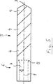
図5に示したドリルロッドは、図1〜図4に示したドリルロッドにほぼ相当している。特に中心切欠き7は、図5に示したドリルロッドでも、シャンク範囲6の、刃溝範囲5に近い方の部分区分8に、シャンク範囲6の、刃溝範囲5と反対の側の端部よりも大きな横断面を有している。しかし、図5に示したドリルロッドでは、中心切欠き7が部分区分8でハンマヘッド状にまたは鳩尾状に形成されている。残りの領域では、中心切欠き7は円筒状に形成されている。しかし、場合によっては、中心切欠き7が残りの部分区分で同じくやや円錐形に延びていてもよい。
The drill rod shown in FIG. 5 substantially corresponds to the drill rod shown in FIGS. In particular, the
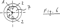
図6〜図8には、中心切欠き7の別の可能な横断面が示してある。この横断面は、図1〜図5に示したドリルロッドに好みにより使用されてもよい。これら全てのドリルロッドには、シャンク範囲6に設けられた中心切欠き7が、円形と異なる形状の横断面を有していることが共通している。さらに、これらのドリルロッドには、案内通路2と中心切欠き7とが互いに連通接続されていることが共通している。
FIGS. 6 to 8 show other possible cross sections of the
図6によれば、シャンク範囲6における横断面が長円形にまたは楕円形に形成されている。図7によれば、シャンク範囲6における横断面が多角形に形成されている。図8によれば、横断面が1つの切欠き9と、たとえばこの切欠き9と反対の側に位置するように、1つの突出部10とを有している。場合によっては、1つよりも多くの切欠き9および/または1つよりも多くの突出部10が設けられていてもよい。場合によっては、図8に示した構成が、図6および図7に示した構成に組み合わされてもよい。
According to FIG. 6, the cross section in the
図5〜図8に示したドリルロッドは案内通路2を有していない。しかし、このドリルロッドはこのような通路2を有していてもよい。また、図1〜図4に示したドリルロッドにおいて案内通路2が場合によって省略されてもよい。
The drill rod shown in FIGS. 5 to 8 does not have the
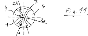
図9〜図12には、いま、別のドリルロッドが示してある。このドリルロッドは、図1〜図8に示したドリルロッドと異なる製作形式で製作可能である。このドリルロッドでは、流動性の焼結材料が成形体に被着させられる。この焼結材料は、たとえばペースト状であってよい。成形体は、たとえば金属、セラミックス、プラスチックまたは容易に溶融可能な材料(一般的には鑞)から成っていてよい。その後、被着させられた焼結材料が乾燥させられるかまたは別の形式で、たとえば予備焼結によって形状安定させられる。その後、成形体が、場合によってはロッド中心軸線を中心として、形状安定させられた焼結材料に対して相対的にねじられて、形状安定させられた焼結ロッドから引き出されるかまたは溶融可能な材料の事例では溶融除去される。刃溝4は択一的に成形体の引出しもしくは溶融除去の前後に、場合によっては焼結ロッドの焼結後にも、この焼結ロッドに加工成形することができる。図9に示したドリルロッドでも、刃溝4はロッド中心軸線1を巡って螺旋状に延びている。中心切欠き7も、少なくとも刃溝範囲5でロッド中心軸線1を巡って螺旋状に延びている。
FIGS. 9 to 12 now show another drill rod. This drill rod can be manufactured in a different manufacturing form from the drill rod shown in FIGS. In this drill rod, a fluid sintered material is applied to the compact. This sintered material may be in the form of a paste, for example. The shaped body may be made of, for example, metal, ceramics, plastic, or an easily meltable material (generally a soot). Thereafter, the deposited sintered material is dried or otherwise stabilized, for example by presintering. Thereafter, the shaped body can be pulled out of the shape-stabilized sintered rod or melted, possibly twisted relative to the shape-stabilized sintered material about the rod center axis. In the material case, it is melted away. The
このドリルロッドでは、中心切欠き7の構成が(かつ一般的には案内通路2の構成も)成形体の形状によって顕著に規定されている。これによって、中心切欠き7がシャンク範囲6を越えてロッド中心軸線1の方向で刃溝範囲5にまで延びていることが可能となる。この場合、円形と異なる形状の横断面に基づき、最大間隔Aが刃溝範囲5でも少なくとも最小間隔aと同じ大きさに設定されていることが可能となる。最大間隔Aを刃溝範囲5で最小間隔aよりも大きく設定することさえもできる。
In this drill rod, the configuration of the center notch 7 (and generally the configuration of the guide passage 2) is markedly defined by the shape of the molded body. This makes it possible for the
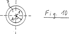
図10〜図12によれば、中心切欠き7がドリル先端部3に向かって先細りにされていて、徐々に案内通路2に移行している。この場合、中心切欠き7は、ドリルロッドがロッド中心軸線1の領域で材料なしに保たれている距離と同じ距離にわたって延びている。中心切欠き7が刃溝範囲5にさらに存在している領域では、中心切欠き7の横断面が刃溝範囲5の外側横断面に適合されており、これによって、刃溝範囲5がほぼ至るところに不変の材料厚さsを有している。
According to FIGS. 10 to 12, the
図9〜図12に示した構成では、中心切欠き7がシャンク範囲6でほぼ円筒状に形成されている。しかし、中心切欠き7は、円形と異なる形状の横断面を有していてもよい。また、中心切欠き7が、シャンク範囲6の、刃部範囲5に近い方の部分区分に、シャンク範囲6の、刃溝範囲5と反対の側の端部よりも大きな横断面を有していてもよい。このためには、成形体が適宜に予備成形されていなければならず、溶融除去可能でなければならない。択一的または付加的には、形状安定させられた焼結材料からの成形体の除去後、中心切欠き7の後加工を行うこともできる。
9 to 12, the
案内通路2は、すでに上述したように、成形体の形状によって規定される。しかし、場合によっては、ドリル先端部3の領域で案内通路2が、たとえば後穿孔によって追補的にドリルロッドに加工成形されてもよい。
As already described above, the
本発明によるドリルロッドもしくは、より一般的には、ワークを切削加工するための本発明による工具によって、従来の工具に比べて著しい材料・重量節約を得ることができる。さらに、運転中の工具に対するコンパクトな保持手段を設けることがより簡単に可能となる。さらに、中心切欠き7のより大きな横断面によって、冷却媒体もしくは潤滑媒体に対する著しく低減された流れ抵抗が得られる。しかし、ドリルロッドの部分的に中空の構成にもかかわらず、このドリルロッドの負荷耐性と性能とは主として低減されていない。
With the drill rod according to the invention or, more generally, the tool according to the invention for machining a workpiece, significant material and weight savings can be obtained compared to conventional tools. Furthermore, it is easier to provide a compact holding means for the tool during operation. Furthermore, the larger cross section of the
1 ロッド中心軸線、 2 案内通路、 3 ドリル先端部、 4 刃溝、 5 刃溝範囲、 6 シャンク範囲、 7 中心切欠き、 8 部分区分、 9 切欠き、 10 突出部、 A 最大間隔、 a 最小間隔、 D 外径、 L 全長、 L1 シャンク長さ、 L2 刃部長さ、 s 材料厚さ 1 Rod center axis, 2 Guide passage, 3 Drill tip, 4 Blade groove, 5 Blade groove range, 6 Shank range, 7 Center notch, 8 Partial section, 9 Notch, 10 Protruding part, A Maximum distance, a Minimum Interval, D outer diameter, L total length, L1 shank length, L2 blade length, s material thickness
Claims (13)
当該工具が、ロッド中心軸線(1)の領域で材料なしの閉鎖された中心切欠き(7)を有しており、該中心切欠き(7)が、工具ホルダの連行体を導入するために設けられていて、ロッド中心軸線(1)の方向でシャンク範囲(6)を越えて刃溝範囲(5)にまで延びていて、該刃溝範囲(5)に円形と異なる形状の横断面を有していて、刃溝範囲(5)にロッド中心軸線(1)から最大間隔(A)を有しており、該最大間隔(A)が、少なくとも最小間隔(a)と同じ大きさに設定されており、当該工具が、一体に形成されていることを特徴とする、ワークを切削加工するためのロッド状の工具。A rod-shaped tool for cutting a workpiece, such as a drill rod, milling rod or reamer rod, made of sintered material, comprising a rod center axis (1), a shank range (6), and a rod center axis A blade groove range (5) adjacent to the shank range (6) in the direction of (1) is provided, and the tool extends to the blade groove range (5) around the rod center axis (1). At least one blade groove (4), and no blade groove (4) in the shank range (6), the blade groove (4) being the minimum distance from the rod center axis (1). In the type having (a),
The tool has a closed center notch (7) without material in the region of the rod center axis (1), the center notch (7) for introducing the tool holder entrainment Provided in the direction of the rod center axis (1), extends beyond the shank range (6) to the blade groove range (5), and the blade groove range (5) has a cross section having a shape different from a circle. And has a maximum interval (A) from the rod center axis (1) in the blade groove range (5), and the maximum interval (A) is set to at least the same size as the minimum interval (a). A rod-shaped tool for cutting a workpiece, characterized in that the tool is integrally formed.
Applications Claiming Priority (2)
| Application Number | Priority Date | Filing Date | Title |
|---|---|---|---|
| DE10142265A DE10142265B4 (en) | 2001-08-29 | 2001-08-29 | Rod-shaped tool for machining a workpiece |
| PCT/EP2002/009038 WO2003020462A1 (en) | 2001-08-29 | 2002-08-13 | Rod-shaped tool for machining a workpiece |
Publications (2)
| Publication Number | Publication Date |
|---|---|
| JP2005501743A JP2005501743A (en) | 2005-01-20 |
| JP4393189B2 true JP4393189B2 (en) | 2010-01-06 |
Family
ID=7696961
Family Applications (1)
| Application Number | Title | Priority Date | Filing Date |
|---|---|---|---|
| JP2003524758A Expired - Lifetime JP4393189B2 (en) | 2001-08-29 | 2002-08-13 | Rod-shaped tool for cutting workpieces |
Country Status (6)
| Country | Link |
|---|---|
| US (1) | US7226254B2 (en) |
| EP (1) | EP1420915B1 (en) |
| JP (1) | JP4393189B2 (en) |
| AT (1) | ATE333333T1 (en) |
| DE (2) | DE10142265B4 (en) |
| WO (1) | WO2003020462A1 (en) |
Families Citing this family (17)
| Publication number | Priority date | Publication date | Assignee | Title |
|---|---|---|---|---|
| SE527227C2 (en) * | 2003-09-12 | 2006-01-24 | Seco Tools Ab | Chip separation machining tool with an axial cylindrical channel |
| DE102004021190A1 (en) * | 2004-04-29 | 2005-12-29 | Günther & Co GmbH | Interface for a cutting tool |
| DE102007044269A1 (en) | 2007-09-17 | 2009-03-19 | Arno Friedrichs | Partially ground tool bar made of sintered material |
| DE102011000352A1 (en) * | 2011-01-27 | 2012-02-16 | Arno Friedrichs | Dental drills and method for its production |
| JP5906842B2 (en) * | 2012-03-14 | 2016-04-20 | 三菱マテリアル株式会社 | Cemented carbide cutting tool |
| DE102013210355B4 (en) * | 2013-06-04 | 2022-11-17 | Kennametal Inc. | Cutting tool and method for producing a cutting tool |
| DE102014207507B4 (en) | 2014-04-17 | 2021-12-16 | Kennametal Inc. | Cutting tool and method for producing a cutting tool |
| DE102014207510B4 (en) | 2014-04-17 | 2021-12-16 | Kennametal Inc. | Cutting tool and method for producing a cutting tool |
| DE102014013210B4 (en) | 2014-09-06 | 2021-10-21 | Audi Ag | Cutting tool with a cooling channel |
| US9643282B2 (en) | 2014-10-17 | 2017-05-09 | Kennametal Inc. | Micro end mill and method of manufacturing same |
| DE102015106374A1 (en) * | 2015-04-24 | 2016-10-27 | Gühring KG | Rotary tool with tapered coolant channel and staggered coolant outlet lines and related manufacturing process |
| AT15226U1 (en) * | 2016-05-20 | 2017-03-15 | Ceratizit Austria Gmbh | Process for the powder metallurgical production of a rod-shaped body |
| EP3533545A1 (en) * | 2018-03-01 | 2019-09-04 | AB Sandvik Coromant | Modular cutting tool body and method for manufacturing the same |
| US11110524B2 (en) * | 2019-03-07 | 2021-09-07 | Kennametal Inc. | Rotary cutting tool with internal coolant passage |
| CN113263211A (en) * | 2021-04-15 | 2021-08-17 | 厦门金鹭特种合金有限公司 | Finish machining single-edge cutter |
| CN113319349A (en) * | 2021-04-15 | 2021-08-31 | 厦门金鹭特种合金有限公司 | Internal cooling tool with jet flow in handle |
| US20230182212A1 (en) | 2021-12-14 | 2023-06-15 | Iscar, Ltd. | Insert holder having weight-reducing voids and cutting tool |
Family Cites Families (17)
| Publication number | Priority date | Publication date | Assignee | Title |
|---|---|---|---|---|
| US839461A (en) * | 1905-09-11 | 1906-12-25 | Henry A Eastman | Drill. |
| US2348874A (en) * | 1943-03-22 | 1944-05-16 | Rudolf W Andreasson | Oilhole drill |
| GB571403A (en) | 1944-01-21 | 1945-08-23 | Thomas Large Phillips | Improvements in drills for producing holes in metal |
| US2482687A (en) * | 1947-09-12 | 1949-09-20 | Mueller Co | Service tau |
| US2903921A (en) * | 1957-10-09 | 1959-09-15 | Rudolf W Andreasson | Drill |
| DE8002631U1 (en) * | 1980-02-01 | 1980-07-10 | Gebrueder Heller Gmbh Werkzeugfabrik, 2807 Achim | DRILL |
| JPS59219108A (en) * | 1983-05-25 | 1984-12-10 | Sumitomo Electric Ind Ltd | Drill |
| DE3629035A1 (en) * | 1986-08-27 | 1988-03-10 | Stellram Gmbh | ONE-PIECE CUTTING TOOL |
| US5234293A (en) * | 1992-06-19 | 1993-08-10 | Mena Carl M | Screw tap with predetermined protective rupture of release point |
| DE19522837A1 (en) * | 1995-06-23 | 1997-01-02 | Beck August Gmbh Co | Drilling tool |
| CN1101744C (en) * | 1995-07-14 | 2003-02-19 | 克纳门特尔-赫特尔刀具及硬质材料股份有限公司 | Drill with cooling-lubricant channel |
| US6116825A (en) * | 1995-08-08 | 2000-09-12 | Kennametal Hertel Ag Werkzeuge + Hartstoffe | Rotating cutting tool with a coolant passage and a method of providing it with coolant |
| SE512456C2 (en) * | 1997-04-11 | 2000-03-20 | Sandvik Ab | Tools for making internal threads |
| JPH11114714A (en) * | 1997-10-09 | 1999-04-27 | Takaya Yoshikura | Drilling part cooling method of rotary drilling bit |
| IL129078A0 (en) * | 1999-03-21 | 2000-02-17 | Micro Tools Ltd | Drill blank |
| DE19942966C2 (en) * | 1999-09-09 | 2001-10-31 | Arno Friedrichs | Method and device for producing a sintered metal blank with internal, helical recesses |
| DE10243104A1 (en) * | 2002-09-17 | 2004-03-25 | Gebr. Brasseler Gmbh & Co. Kg | Rotating ceramic tool with a ceramic cutting head bonded to a ceramic or metal support shaft |
-
2001
- 2001-08-29 DE DE10142265A patent/DE10142265B4/en not_active Expired - Fee Related
-
2002
- 2002-08-13 US US10/488,181 patent/US7226254B2/en not_active Expired - Lifetime
- 2002-08-13 DE DE50207574T patent/DE50207574D1/en not_active Expired - Lifetime
- 2002-08-13 AT AT02767373T patent/ATE333333T1/en active
- 2002-08-13 JP JP2003524758A patent/JP4393189B2/en not_active Expired - Lifetime
- 2002-08-13 EP EP02767373A patent/EP1420915B1/en not_active Expired - Lifetime
- 2002-08-13 WO PCT/EP2002/009038 patent/WO2003020462A1/en active IP Right Grant
Also Published As
| Publication number | Publication date |
|---|---|
| JP2005501743A (en) | 2005-01-20 |
| DE50207574D1 (en) | 2006-08-31 |
| EP1420915A1 (en) | 2004-05-26 |
| ATE333333T1 (en) | 2006-08-15 |
| EP1420915B1 (en) | 2006-07-19 |
| US7226254B2 (en) | 2007-06-05 |
| DE10142265A1 (en) | 2003-03-27 |
| US20050084351A1 (en) | 2005-04-21 |
| WO2003020462A1 (en) | 2003-03-13 |
| DE10142265B4 (en) | 2005-04-28 |
Similar Documents
| Publication | Publication Date | Title |
|---|---|---|
| JP4393189B2 (en) | Rod-shaped tool for cutting workpieces | |
| US4704055A (en) | Drill with cooling channel | |
| RU2304036C2 (en) | Pressed powder blank forming method | |
| EP0891239B1 (en) | Twist drill with asymmetrically spaced support margins | |
| US2422994A (en) | Twist drill | |
| US5800101A (en) | Drill | |
| RU2465101C2 (en) | Cutting tool | |
| US2237901A (en) | Drill | |
| US6948890B2 (en) | Drill having internal chip channel and internal flush channel | |
| KR100838767B1 (en) | Twist drill | |
| US20060027046A1 (en) | Method and device for manufacturing a drill blank or a mill blank | |
| KR20080008318A (en) | Deep hole drill | |
| KR19980081837A (en) | drill | |
| KR20020091197A (en) | Drill with improved cutting insert formation | |
| JP5306351B2 (en) | Partly ground tool rod made of sintered material | |
| KR20040048994A (en) | Tool for chip forming machining | |
| CZ246198A3 (en) | Drilling tool for machine-tools and process for producing thereof | |
| CN111515438A (en) | Drilling tool and method for producing a drill hole | |
| JPS61226231A (en) | Manufacture of ultrahard solid drill formed with oil hole | |
| JPS6312891Y2 (en) | ||
| KR100649431B1 (en) | Drill provided with fluid guide means | |
| JPH05261612A (en) | Drill | |
| JPH069813U (en) | Drill | |
| JP2003277807A (en) | Method for manufacturing supper hard alloy oil hole drill, and supper hard alloy oil hole drill | |
| DE20300520U1 (en) | Rotary shaft tool, in particular bore post-processing tool |
Legal Events
| Date | Code | Title | Description |
|---|---|---|---|
| A621 | Written request for application examination |
Free format text: JAPANESE INTERMEDIATE CODE: A621 Effective date: 20050630 |
|
| A131 | Notification of reasons for refusal |
Free format text: JAPANESE INTERMEDIATE CODE: A131 Effective date: 20080326 |
|
| A521 | Request for written amendment filed |
Free format text: JAPANESE INTERMEDIATE CODE: A523 Effective date: 20080616 |
|
| A131 | Notification of reasons for refusal |
Free format text: JAPANESE INTERMEDIATE CODE: A131 Effective date: 20090123 |
|
| A601 | Written request for extension of time |
Free format text: JAPANESE INTERMEDIATE CODE: A601 Effective date: 20090423 |
|
| A602 | Written permission of extension of time |
Free format text: JAPANESE INTERMEDIATE CODE: A602 Effective date: 20090501 |
|
| A521 | Request for written amendment filed |
Free format text: JAPANESE INTERMEDIATE CODE: A523 Effective date: 20090521 |
|
| TRDD | Decision of grant or rejection written | ||
| A01 | Written decision to grant a patent or to grant a registration (utility model) |
Free format text: JAPANESE INTERMEDIATE CODE: A01 Effective date: 20090911 |
|
| A01 | Written decision to grant a patent or to grant a registration (utility model) |
Free format text: JAPANESE INTERMEDIATE CODE: A01 |
|
| A61 | First payment of annual fees (during grant procedure) |
Free format text: JAPANESE INTERMEDIATE CODE: A61 Effective date: 20091013 |
|
| R150 | Certificate of patent or registration of utility model |
Ref document number: 4393189 Country of ref document: JP Free format text: JAPANESE INTERMEDIATE CODE: R150 Free format text: JAPANESE INTERMEDIATE CODE: R150 |
|
| FPAY | Renewal fee payment (event date is renewal date of database) |
Free format text: PAYMENT UNTIL: 20121023 Year of fee payment: 3 |
|
| FPAY | Renewal fee payment (event date is renewal date of database) |
Free format text: PAYMENT UNTIL: 20131023 Year of fee payment: 4 |
|
| R250 | Receipt of annual fees |
Free format text: JAPANESE INTERMEDIATE CODE: R250 |
|
| R250 | Receipt of annual fees |
Free format text: JAPANESE INTERMEDIATE CODE: R250 |
|
| R250 | Receipt of annual fees |
Free format text: JAPANESE INTERMEDIATE CODE: R250 |
|
| R250 | Receipt of annual fees |
Free format text: JAPANESE INTERMEDIATE CODE: R250 |
|
| R250 | Receipt of annual fees |
Free format text: JAPANESE INTERMEDIATE CODE: R250 |
|
| R250 | Receipt of annual fees |
Free format text: JAPANESE INTERMEDIATE CODE: R250 |
|
| R250 | Receipt of annual fees |
Free format text: JAPANESE INTERMEDIATE CODE: R250 |
|
| R250 | Receipt of annual fees |
Free format text: JAPANESE INTERMEDIATE CODE: R250 |
|
| S111 | Request for change of ownership or part of ownership |
Free format text: JAPANESE INTERMEDIATE CODE: R313113 |
|
| R350 | Written notification of registration of transfer |
Free format text: JAPANESE INTERMEDIATE CODE: R350 |
|
| R250 | Receipt of annual fees |
Free format text: JAPANESE INTERMEDIATE CODE: R250 |
|
| R250 | Receipt of annual fees |
Free format text: JAPANESE INTERMEDIATE CODE: R250 |
|
| EXPY | Cancellation because of completion of term |