JP4391436B2 - 3-position switch - Google Patents
3-position switch Download PDFInfo
- Publication number
- JP4391436B2 JP4391436B2 JP2005083333A JP2005083333A JP4391436B2 JP 4391436 B2 JP4391436 B2 JP 4391436B2 JP 2005083333 A JP2005083333 A JP 2005083333A JP 2005083333 A JP2005083333 A JP 2005083333A JP 4391436 B2 JP4391436 B2 JP 4391436B2
- Authority
- JP
- Japan
- Prior art keywords
- movable contact
- piece
- contact piece
- base
- inclined surface
- Prior art date
- Legal status (The legal status is an assumption and is not a legal conclusion. Google has not performed a legal analysis and makes no representation as to the accuracy of the status listed.)
- Expired - Fee Related
Links
Images


Landscapes
- Push-Button Switches (AREA)
Description
本発明は、押ボタンスイッチに係り、特にOFF−ON−OFFの3ポジションスイッチ(イネーブルスイッチ)に関するものである。 The present invention relates to a pushbutton switch, and more particularly to an OFF-ON-OFF three-position switch (enable switch).
従来、ロボットの教示装置やラインにおける制御操作スイッチとしては、手元に携帯する押ボタンスイッチが用いられている。特に、近年では、人間工学に基づいて危険を回避できるスイッチとして、3ポジションスイッチ(イネーブルスイッチ)が普及してきている。かかる3ポジションスイッチは、操作しない状態ではOFFであり、制御対象物を操作するために押ボタンを押すとONになり、押ボタンを解放するとOFFに復帰する。また、ONの状態からさらに押ボタンを押し込む操作によってもスイッチをOFFにすることができる。すなわち、制御対象物の暴走や操作者の不注意などにより予期せぬ異常動作が起こり、操作者に危害が及ぶような場合には、操作者は押ボタンを解放するか、さらに押ボタンを押し込むかの何れかの行動をとる。つまり、咄嗟に押ボタンを押す、あるいは離す、どちらの動作を行っても、即座にスイッチがONからOFFになるように構成されている。そのため、3ポジションスイッチは、フェイルセーフに働く安全なスイッチといえる(下記特許文献1〜4参照)。
しかしながら、かかる従来の3ポジションスイッチは構造が複雑で、大きく、コストが高いといった問題があった。
本発明は、上記状況に鑑みて、操作機械の突然の異常に際して回路を確実に遮断することができ、しかも構造が簡単で、安定な動作を行うことができるコンパクトな3ポジションスイッチを提供することを目的とする。
However, such a conventional three-position switch has a complicated structure, a large size, and a high cost.
In view of the above situation, the present invention provides a compact three-position switch that can reliably shut off a circuit in the event of a sudden abnormality of an operating machine, that is simple in structure, and that can perform a stable operation. With the goal.
本発明は、上記目的を達成するために、
〔1〕3ポジションスイッチにおいて、ベースに被着されるハウジングと、このハウジングの中央部に配置されるとともに、両側の面になだらかな傾斜面と急峻な傾斜面が形成されたカム部が設けられたプランジャを有する押ボタンと、前記プランジャの下部と前記ベース間に配置される復帰用バネと、前記ベースに水平方向に形成される溝に枢支されるともに、前記カム部に係合する滑動子付き転換子を有する揺動片と、この揺動片の反転用バネを介した傾動に応動する可動接片と、前記ベースに固定され、前記可動接片の変位によりこの可動接片と接触可能な固定接触部を有する固定端子とを備え、前記押ボタンの第1段の押圧操作により、前記カム部に係合したままで、前記揺動片の上下の傾きが反転し、それにより前記反転用バネが反転し、この反転用バネの反転で前記可動接片を上昇させて前記固定端子の固定接触部に前記可動接片を接触させて回路を閉路し、この時点で押ボタンを解放すると前記固定接触部から可動接片は離れて開路し、前記第1段の押ボタンの更なる押し込みによる第2段の操作により、前記転換子の滑動子が前記カム部の急峻な傾斜面を乗り越えてなだらかな傾斜面に移動することにより、前記揺動片の上下の傾きがさらに反転し、前記反転用バネの逆向きの反転で前記可動接片を下降させて前記固定接触部から前記可動接片を離して回路を開路することを特徴とする。
In order to achieve the above object, the present invention provides
[1] A three-position switch is provided with a housing attached to the base and a cam portion which is disposed at the center portion of the housing and has a gentle inclined surface and a steep inclined surface on both side surfaces. A push button having a plunger, a return spring disposed between the lower portion of the plunger and the base, and a slide that is pivotally supported by a groove formed in a horizontal direction on the base and engages with the cam portion. An oscillating piece having a converter with a child, a movable contact piece that responds to tilting of the oscillating piece through a reversing spring, and fixed to the base, and contacts the movable contact piece by displacement of the movable contact piece. and a fixed terminal having a fixed contact portion as possible, by the first-stage pressing operation of the push button, while engaged with the cam portion, the upper and lower and tilt Kiga reversal of the oscillating piece, thereby The reversing spring The movable contact piece is raised by reversing the reversing spring to bring the movable contact piece into contact with the fixed contact portion of the fixed terminal to close the circuit. At this point, the push button is released to release the fixed contact. The movable contact piece is opened away from the part, and the second stage operation by further pushing the first stage push button causes the slider of the converter to move over the steep inclined surface of the cam part. by moving the inclined surface, and inversion and below the tilting Kigasara of the swinging piece, the movable contact from the fixed contact portion in a reverse inversion lowers the movable contact piece of the reversing spring The circuit is opened by separating the pieces.
〔2〕上記〔1〕記載の3ポジションスイッチにおいて、前記ベースに水平方向に形成される溝が前記転換子の滑動子の後方への移動を可能にし、前記滑動子の前記カム部の急峻な傾斜面からなだらかな傾斜面への離脱を円滑にすることを特徴とする。
〔3〕上記〔1〕又は〔2〕記載の3ポジションスイッチにおいて、片側に1回路、両側で2回路の開閉を行うことを特徴とする。
[2] In the three-position switch described in [1], a groove formed in the base in a horizontal direction enables the slider to move rearward of the slider, so that the cam portion of the slider has a sharp shape. It is characterized by facilitating the separation from the inclined surface to the gently inclined surface.
[3] The three-position switch according to [1] or [2], wherein one circuit is opened and closed on one side and two circuits are opened and closed on both sides.
本発明によれば、構造が簡単で、安定な動作を行うことができるコンパクトな3ポジションスイッチを提供することができる。 According to the present invention, a compact three-position switch having a simple structure and capable of performing a stable operation can be provided.
本発明の3ポジションスイッチは、ベースに被着されるハウジングと、このハウジングの中央部に配置されるとともに、両側の面になだらかな傾斜面と急峻な傾斜面が形成されたカム部が設けられたプランジャを有する押ボタンと、前記プランジャの下部と前記ベース間に配置される復帰用バネと、前記ベースに水平方向に形成される溝に枢支されるともに、前記カム部に係合する滑動子付き転換子を有する揺動片と、この揺動片の反転用バネを介した傾動に応動する可動接片と、前記ベースに固定され、前記可動接片の変位によりこの可動接片と接触可能な固定接触部を有する固定端子とを備え、前記押ボタンの第1段の押圧操作により、前記カム部に係合したままで、前記揺動片の上下の傾きが反転し、それにより前記反転用バネが反転し、この反転用バネの反転で前記可動接片を上昇させて前記固定端子の固定接触部に前記可動接片を接触させて回路を閉路し、この時点で押ボタンを解放すると前記固定接触部から可動接片は離れて開路し、前記第1段の押ボタンの更なる押し込みによる第2段の操作により、前記転換子の滑動子が前記カム部の急峻な傾斜面を乗り越えてなだらかな傾斜面に移動することにより、前記揺動片の上下の傾きがさらに反転し、前記反転用バネの逆向きの反転で前記可動接片を下降させて前記固定接触部から前記可動接片を離して回路を開路する。これにより、操作機械の突然の異常に対して、回路を確実に遮断することができ、構造が簡単で、安定な動作を行うことができるコンパクトな3ポジションスイッチを実現する。 The three-position switch of the present invention is provided with a housing attached to the base, and a cam portion which is disposed at the center portion of the housing and has a gentle inclined surface and a steep inclined surface on both side surfaces. A push button having a plunger, a return spring disposed between the lower portion of the plunger and the base, and a slide that is pivotally supported by a groove formed in a horizontal direction on the base and engages with the cam portion. An oscillating piece having a converter with a child, a movable contact piece that responds to tilting of the oscillating piece through a reversing spring, and fixed to the base, and contacts the movable contact piece by displacement of the movable contact piece. and a fixed terminal having a fixed contact portion as possible, by the first-stage pressing operation of the push button, while engaged with the cam portion, the upper and lower and tilt Kiga reversal of the oscillating piece, thereby The reversing spring is reversed The reversing spring reverses the movable contact piece to bring the movable contact piece into contact with the fixed contact portion of the fixed terminal to close the circuit, and when the push button is released at this point, the fixed contact portion The movable contact piece opens away, and the second stage operation by further pushing the first stage push button causes the slider of the converter to move over the steep inclined surface of the cam portion, and the gentle inclined surface. by moving to, the above-inversion and below the tilting Kigasara the swinging piece, the movable contact piece from the fixed contact portion is moved downward the movable contact piece in the opposite direction of reversal of the reversing spring Release to open the circuit. As a result, it is possible to realize a compact three-position switch that can reliably shut off the circuit against a sudden abnormality of the operating machine, has a simple structure, and can perform a stable operation.
以下、本発明の実施例について、図面を参照しながら詳細に説明する。
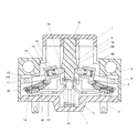
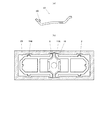
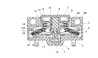
図1は本発明の実施例を示す3ポジションスイッチの構成断面図、図2はベースの全体斜視図、図3はそのベースの片側の斜視図、図4は固定端子の配置図、図5はそのハウジングの斜視図、図6はその押ボタンの斜視図、図7はそのプランジャ及び復帰用コイルバネの斜視図、図8はその可動接片の構成図であり、図8(a)はその断面図、図8(b)はその平面図、図9はその揺動片の斜視図である。
Hereinafter, embodiments of the present invention will be described in detail with reference to the drawings.
1 is a cross-sectional view of a three-position switch showing an embodiment of the present invention, FIG. 2 is an overall perspective view of the base, FIG. 3 is a perspective view of one side of the base, FIG. 4 is a layout view of fixed terminals, and FIG. FIG. 6 is a perspective view of the push button, FIG. 7 is a perspective view of the plunger and the return coil spring, FIG. 8 is a configuration diagram of the movable contact piece, and FIG. FIG. 8B is a plan view thereof, and FIG. 9 is a perspective view of the swing piece.
これらの図において、1はベースであり、図3に示すように、突起1Gと嵌合穴1H(突起1Gに対向する嵌合穴、嵌合穴1Hに対向する突起は図示なし)との嵌着により、図2に示すように、ベース1Aとベース1Bとが組み付けられてベース1が構成される。そのベース1には中央に突出部1C、両側に突出部1Dが形成され、突出部1Dには外側から内側に溝6が形成され、この溝6には後述する揺動片12の枢支部12Aが係合するように構成されている。また、中央の突出部1Cには後述する可動接片19の枢支部19Aが係合する係止部1Eが形成されている。また、ベース1の外側面には図2に示すように後述するハウジング5の嵌合穴5Bに嵌着される突起1Fが形成されている。さらに、ベース1の内側には図3に示すように嵌合穴1Jが形成され、その部分に図4に示すような配置で固定端子2が植設されるようになっている。なお、3は固定接触部である。
In these drawings,
5はハウジングであり、このハウジング5の下部の開口部はベース1で塞がれるように、ベース1と組み合わされる。図5に示すように、そのハウジング5の上面の中央部には後述する押ボタン7が係合する開口部5Aが形成されており、また、側面の下部には上記したベース1の突起1Fが嵌着される嵌合穴5Bが形成されている。
7は押ボタンであり、ハウジング5の開口部5Aに係合され、図6に示すように、下部にストッパー7A、側面に後述するプランジャ8の突起8Bが係合する係合穴7Bが形成されている。
8は押ボタン7の中央から下方に延びるように形成されるプランジャであり、図7に示すように、案内部8A、押ボタン7の係合穴7Bに係合する突起8B、プランジャ8の両側に設けられるカム部9が形成されている。このカム部9はなだらかな傾斜面9Aと急峻な傾斜面9Bからなり、後述する滑動子16との協働によりクイックアクション機能を有する。プランジャ8の下部には復帰用コイルバネ10が配置される。
19は可動接片であり、図8に示すように、基部に枢支部19Aが形成されており、この枢支部19Aがベース1の係止部1Eに係合されて、可動接片19に形成される可動接触部19Bの上下方向への揺動を行わせる。この可動接触部19Bが揺動して、固定端子2の固定接触部3に接触することにより、回路はオンとなる。可動接片19の先端部には突起20が形成されており、この突起20と後述する転換子13の後端下方の突起17との間に反転用コイルスプリング18が装着されて、可動接片19の急速揺動動作を可能にする。
12は揺動片であり、図9に示すように、股状の構造をしており、その脚部に枢支部12Aが形成されており、この枢支部12Aはベース1の両側の突出部1Dに形成された溝6に係合され、この枢支部12Aを支点として回転可能に枢支されるとともに、溝6に沿って水平方向に若干移動可能に枢支されるように構成されている。かかる構造としているために、転換子13を有する揺動片12の上下の傾きが反転する際の動作が円滑なものとなる。
この揺動片12の先端部分には転換子13が設けられ、この転換子13には内部にくり抜き穴14が形成されており、このくり抜き穴14内に密着巻のコイルスプリング15を介して滑動子16が上記したプランジャ8のカム部9に沿って移動できるように装着されている。転換子13の後端下方には突起17が形成されており、上記した可動接片19の先端部の突起20に他端が係合する反転用コイルスプリング18の一端が係合されている。そこで、その可動接片19は、転換子13の動作に伴ってその位置が上昇すると可動接触部19Bが固定接片2の固定接触部3に接触して、回路がONとなり、下降すると回路がOFFとなる。
A
図10〜図12は本発明の3ポジションスイッチの動作の説明図である。
(1)まず、図10に示すように、押ボタン7が押されていない場合には、図1と同様であり、可動接片19は下降しており、回路はOFFの状態である。
(2)次に、図11に示すように、押ボタン7が押される(押ボタン7を軽く操作する)と、プランジャ8は押し下げられる。すると、プランジャ8のカム部9も下がるが、滑動子16はカム部9の急峻な傾斜面9Bに係合したまま、下方に押し下げられるので、転換子13の突起17は上方を向くことになり、そのために反転用コイルスプリング18は反転する。すると反転用コイルスプリング18のもう一方の端部が可動接片19の突起20に係合しているので、可動接片19は上昇して固定接触部3に接触することにより、回路がONとなる。なお、この図11の状態で操作者が押ボタン7から手を離し押ボタン7を解放すると、ベース1の凹部に配置された復帰用スプリング10がプランジャ8を押し上げるため、図10の状態に戻って回路はOFFとなる。
10 to 12 are explanatory views of the operation of the three-position switch of the present invention.
(1) First, as shown in FIG. 10, when the
(2) Next, as shown in FIG. 11, when the
(3)次に、この3ポジションスイッチの押ボタン7を更に押し込む(押ボタン7を強く操作する)と、図12に示すように、転換子13及び揺動片12の支点11は溝6内を後方に移動し、滑動子16は急峻な傾斜面9Bを乗り越えて、なだらかな面9Aを滑り降りる。すると、転換子13の後端下方の突起17は下方を向くので、反転用コイルスプリング18のもう一方の端部が係合する可動接片19は下方へ移動することになり、回路はOFFとなる。
(3) Next, when the
このように構成したので、例えば、操作対象物や操作者が何らかの異常状態に陥って押ボタンを更に強く押した状態であっても、図12のように回路はOFF状態となる。つまり、押ボタンを放した場合、また、更に強く押した場合のいずれの場合でも、フェールセーフに作用するので、極めて安全な制御操作用3ポジションスイッチとして機能することができる。 With this configuration, for example, even when the operation target or the operator falls into some abnormal state and presses the push button more strongly, the circuit is turned off as shown in FIG. That is, when the push button is released or when the push button is further pressed, it acts as a fail safe, and can function as an extremely safe three-position switch for control operation.
更に、本発明の3ポジションスイッチは、中央にカム部を有するプランジャを配置し、その両側にクイックアクション機能を有するスイッチ開閉部を配置するようにしたので、安定感があり、コンパクトで堅牢に構成することができる。
また、前後に一対の固定端子2を図4に示すように左右に配置し、可動接片19の上昇により対峙した固定端子2の固定接触部3を可動接片19で橋絡して回路を閉成し、可動接片19の下降により対峙した固定端子2の固定接触部3から可動接片19を離脱して回路を開成する。このように、開閉機構が左右に配置されるので、1個のスイッチで合計2回路の開閉を行うことができる。
Furthermore, the 3-position switch of the present invention has a plunger with a cam portion at the center and switch opening / closing portions with a quick action function on both sides, so it has a sense of stability and is compact and robust. can do.
Further, disposed on the left and right as shown in FIG. 4 the pair of fixed
このように、本発明によれば、操作機械の突然の異常に際して、回路を確実に遮断することができるとともに、コンパクトなスイッチでありながら、多くの回路の開閉を行わせることができる。
なお、本発明は上記実施例に限定されるものではなく、本発明の趣旨に基づき種々の変形が可能であり、これらを本発明の範囲から排除するものではない。
As described above, according to the present invention, in the event of a sudden abnormality of the operating machine, the circuit can be reliably shut off and many circuits can be opened and closed while being a compact switch.
In addition, this invention is not limited to the said Example, A various deformation | transformation is possible based on the meaning of this invention, and these are not excluded from the scope of the present invention.
本発明の3ポジションスイッチは、操作者が押ボタンスイッチの押圧動作を解放しても、または更に強く押し込んでもスイッチをOFF状態にできるといったフェィルセーフ機能を有する押ボタンスイッチとして利用可能である。 The three-position switch of the present invention can be used as a pushbutton switch having a fail-safe function in which the switch can be turned off even if the operator releases the pushbutton switch or further presses the pushbutton switch.
1,1A,1B ベース
1C 中央の突出部
1D 両側の突出部
1E 係止部
1F,1G,8B,17,20 突起
1H,1J,5B 嵌合穴
7B 係合穴
2 固定端子
3 固定接触部
5 ハウジング
5A 開口部
6 溝
7 押ボタン
7A ストッパー
8 プランジャ
8A 案内部
9 カム部
9A なだらかな傾斜面
9B 急峻な傾斜面
10 復帰用コイルバネ
12 揺動片
12A,19A 枢支部
13 転換子
14 くり抜き穴
15 密着巻のコイルスプリング
16 滑動子
18 反転用コイルスプリング
19 可動接片
19B 可動接触部
1, 1A,
7
Claims (3)
(b)該ハウジングの中央部に配置されるとともに、両側の面になだらかな傾斜面と急峻な傾斜面が形成されたカム部が設けられたプランジャを有する押ボタンと、
(c)前記プランジャの下部と前記ベース間に配置される復帰用バネと、
(d)前記ベースに水平方向に形成される溝に枢支されるともに、前記カム部に係合する滑動子付き転換子を有する揺動片と、
(e)該揺動片の反転用バネを介した傾動に応動する可動接片と、
(f)前記ベースに固定され、前記可動接片の変位により該可動接片と接触可能な固定接触部を有する固定端子とを備え、
(g)前記押ボタンの第1段の押圧操作により、前記カム部に係合したままで、前記揺動片の上下の傾きが反転し、それにより前記反転用バネが反転し、該反転用バネの反転で前記可動接片を上昇させて前記固定端子の固定接触部に前記可動接片を接触させて回路を閉路し、この時点で押ボタンを解放すると前記固定接触部から可動接片は離れて開路し、前記第1段の押ボタンの更なる押し込みによる第2段の操作により、前記転換子の滑動子が前記カム部の急峻な傾斜面を乗り越えてなだらかな傾斜面に移動することにより、前記揺動片の上下の傾きがさらに反転し、前記反転用バネの逆向きの反転で前記可動接片を下降させて前記固定接触部から前記可動接片を離して回路を開路することを特徴とする3ポジションスイッチ。 (A) a housing attached to the base;
(B) a pushbutton having a plunger disposed at the center of the housing and provided with a cam portion in which a gentle inclined surface and a steep inclined surface are formed on both side surfaces;
(C) a return spring disposed between the lower portion of the plunger and the base;
(D) an oscillating piece pivotally supported by a groove formed in a horizontal direction in the base and having a converter with a slider engaged with the cam portion;
(E) a movable contact piece that responds to tilting of the swinging piece via a reversing spring;
(F) a fixed terminal that is fixed to the base and has a fixed contact portion that can come into contact with the movable contact piece by displacement of the movable contact piece;
(G) the first-stage pressing operation of the push button, while engaged with the cam portion, and the upper and lower inclined Kiga reversal of the oscillating piece, thereby the spring is reversed for the reversal, the inversion When the movable contact piece is raised by reversing the spring, the movable contact piece is brought into contact with the fixed contact portion of the fixed terminal to close the circuit, and when the push button is released at this point, the movable contact piece is moved from the fixed contact portion. Is opened, and the slider of the converter moves over the steep inclined surface of the cam portion and moves to the gentle inclined surface by the second step operation by further pressing the first-stage push button. by, and inversion and below the tilting Kigasara of the swinging piece, away the movable contact piece from the fixed contact portion in a reverse inversion lowers the movable contact piece of the reversing spring circuit 3 position switch characterized by opening the circuit.
Priority Applications (1)
| Application Number | Priority Date | Filing Date | Title |
|---|---|---|---|
| JP2005083333A JP4391436B2 (en) | 2005-03-23 | 2005-03-23 | 3-position switch |
Applications Claiming Priority (1)
| Application Number | Priority Date | Filing Date | Title |
|---|---|---|---|
| JP2005083333A JP4391436B2 (en) | 2005-03-23 | 2005-03-23 | 3-position switch |
Publications (2)
| Publication Number | Publication Date |
|---|---|
| JP2006269157A JP2006269157A (en) | 2006-10-05 |
| JP4391436B2 true JP4391436B2 (en) | 2009-12-24 |
Family
ID=37204898
Family Applications (1)
| Application Number | Title | Priority Date | Filing Date |
|---|---|---|---|
| JP2005083333A Expired - Fee Related JP4391436B2 (en) | 2005-03-23 | 2005-03-23 | 3-position switch |
Country Status (1)
| Country | Link |
|---|---|
| JP (1) | JP4391436B2 (en) |
Families Citing this family (5)
| Publication number | Priority date | Publication date | Assignee | Title |
|---|---|---|---|---|
| KR101376078B1 (en) | 2014-01-08 | 2014-03-19 | 이지세이버 주식회사 | High current 3-way switch and intelligent plug socket including the same |
| JP6437254B2 (en) * | 2014-09-17 | 2018-12-12 | 新晃電機株式会社 | Enable switch |
| CN109803505B (en) * | 2019-03-01 | 2023-09-01 | 温州金宏电器有限公司 | Wireless transmitter |
| JP7281785B2 (en) * | 2019-10-25 | 2023-05-26 | パナソニックIpマネジメント株式会社 | Switch device and fault diagnosis method for switch device |
| WO2023032846A1 (en) * | 2021-08-30 | 2023-03-09 | Idec株式会社 | Enabling switch |
-
2005
- 2005-03-23 JP JP2005083333A patent/JP4391436B2/en not_active Expired - Fee Related
Also Published As
| Publication number | Publication date |
|---|---|
| JP2006269157A (en) | 2006-10-05 |
Similar Documents
| Publication | Publication Date | Title |
|---|---|---|
| US7022927B2 (en) | Keyboards with elevated keys | |
| JP4391436B2 (en) | 3-position switch | |
| JP5542545B2 (en) | Disconnector | |
| JP2006269439A (en) | Key switch and keyboard | |
| JP2000331563A (en) | Push button switch | |
| JP2961098B2 (en) | Interlock device for push button switch | |
| JP7007441B2 (en) | Central lock dual lighting switch | |
| JPH10223088A (en) | Interlock device for push-button switch | |
| JP4085686B2 (en) | Enable switch | |
| WO2020067001A1 (en) | Enabling switch | |
| US4795860A (en) | Push switch | |
| JP7359093B2 (en) | changeover switch | |
| JP3372937B2 (en) | Push button switch | |
| JP2002075121A (en) | Switch device and safety device using the same | |
| JP4043313B2 (en) | Push button switch | |
| JP3392840B2 (en) | Key switch device | |
| JP3139580B2 (en) | Push button switch | |
| JP4553310B2 (en) | Switch mechanism | |
| JP3352674B2 (en) | Key switch device | |
| JPH0648611B2 (en) | Interlock device for push button switch | |
| JPH0719073Y2 (en) | Switch device | |
| JP2004342502A (en) | Compound action operating switch | |
| JP2020053328A (en) | Enabling switch | |
| JP2008147039A (en) | Seesaw switch | |
| JPH05109337A (en) | Interlocking unit for push-botton switch |
Legal Events
| Date | Code | Title | Description |
|---|---|---|---|
| A621 | Written request for application examination |
Free format text: JAPANESE INTERMEDIATE CODE: A621 Effective date: 20070226 |
|
| A977 | Report on retrieval |
Free format text: JAPANESE INTERMEDIATE CODE: A971007 Effective date: 20090623 |
|
| A131 | Notification of reasons for refusal |
Free format text: JAPANESE INTERMEDIATE CODE: A131 Effective date: 20090714 |
|
| A521 | Written amendment |
Free format text: JAPANESE INTERMEDIATE CODE: A523 Effective date: 20090730 |
|
| TRDD | Decision of grant or rejection written | ||
| A01 | Written decision to grant a patent or to grant a registration (utility model) |
Free format text: JAPANESE INTERMEDIATE CODE: A01 Effective date: 20091006 |
|
| A01 | Written decision to grant a patent or to grant a registration (utility model) |
Free format text: JAPANESE INTERMEDIATE CODE: A01 |
|
| A61 | First payment of annual fees (during grant procedure) |
Free format text: JAPANESE INTERMEDIATE CODE: A61 Effective date: 20091007 |
|
| FPAY | Renewal fee payment (event date is renewal date of database) |
Free format text: PAYMENT UNTIL: 20121016 Year of fee payment: 3 |
|
| R150 | Certificate of patent or registration of utility model |
Free format text: JAPANESE INTERMEDIATE CODE: R150 |
|
| FPAY | Renewal fee payment (event date is renewal date of database) |
Free format text: PAYMENT UNTIL: 20121016 Year of fee payment: 3 |
|
| FPAY | Renewal fee payment (event date is renewal date of database) |
Free format text: PAYMENT UNTIL: 20131016 Year of fee payment: 4 |
|
| FPAY | Renewal fee payment (event date is renewal date of database) |
Free format text: PAYMENT UNTIL: 20131016 Year of fee payment: 4 |
|
| FPAY | Renewal fee payment (event date is renewal date of database) |
Free format text: PAYMENT UNTIL: 20141016 Year of fee payment: 5 |
|
| S533 | Written request for registration of change of name |
Free format text: JAPANESE INTERMEDIATE CODE: R313533 |
|
| R350 | Written notification of registration of transfer |
Free format text: JAPANESE INTERMEDIATE CODE: R350 |
|
| LAPS | Cancellation because of no payment of annual fees |