JP4391016B2 - Current breaker for electrochemical battery - Google Patents
Current breaker for electrochemical battery Download PDFInfo
- Publication number
- JP4391016B2 JP4391016B2 JP2000508150A JP2000508150A JP4391016B2 JP 4391016 B2 JP4391016 B2 JP 4391016B2 JP 2000508150 A JP2000508150 A JP 2000508150A JP 2000508150 A JP2000508150 A JP 2000508150A JP 4391016 B2 JP4391016 B2 JP 4391016B2
- Authority
- JP
- Japan
- Prior art keywords
- assembly
- battery
- current interrupt
- current
- electrochemical cell
- Prior art date
- Legal status (The legal status is an assumption and is not a legal conclusion. Google has not performed a legal analysis and makes no representation as to the accuracy of the status listed.)
- Expired - Fee Related
Links
Images


Classifications
-
- H—ELECTRICITY
- H01—ELECTRIC ELEMENTS
- H01M—PROCESSES OR MEANS, e.g. BATTERIES, FOR THE DIRECT CONVERSION OF CHEMICAL ENERGY INTO ELECTRICAL ENERGY
- H01M50/00—Constructional details or processes of manufacture of the non-active parts of electrochemical cells other than fuel cells, e.g. hybrid cells
- H01M50/50—Current conducting connections for cells or batteries
- H01M50/572—Means for preventing undesired use or discharge
- H01M50/574—Devices or arrangements for the interruption of current
- H01M50/581—Devices or arrangements for the interruption of current in response to temperature
-
- H—ELECTRICITY
- H01—ELECTRIC ELEMENTS
- H01H—ELECTRIC SWITCHES; RELAYS; SELECTORS; EMERGENCY PROTECTIVE DEVICES
- H01H37/00—Thermally-actuated switches
- H01H37/02—Details
- H01H37/04—Bases; Housings; Mountings
- H01H37/043—Mountings on controlled apparatus
-
- H—ELECTRICITY
- H01—ELECTRIC ELEMENTS
- H01H—ELECTRIC SWITCHES; RELAYS; SELECTORS; EMERGENCY PROTECTIVE DEVICES
- H01H9/00—Details of switching devices, not covered by groups H01H1/00 - H01H7/00
- H01H9/02—Bases, casings, or covers
- H01H9/0271—Bases, casings, or covers structurally combining a switch and an electronic component
-
- H—ELECTRICITY
- H01—ELECTRIC ELEMENTS
- H01M—PROCESSES OR MEANS, e.g. BATTERIES, FOR THE DIRECT CONVERSION OF CHEMICAL ENERGY INTO ELECTRICAL ENERGY
- H01M50/00—Constructional details or processes of manufacture of the non-active parts of electrochemical cells other than fuel cells, e.g. hybrid cells
- H01M50/50—Current conducting connections for cells or batteries
- H01M50/572—Means for preventing undesired use or discharge
- H01M50/574—Devices or arrangements for the interruption of current
-
- H—ELECTRICITY
- H01—ELECTRIC ELEMENTS
- H01H—ELECTRIC SWITCHES; RELAYS; SELECTORS; EMERGENCY PROTECTIVE DEVICES
- H01H35/00—Switches operated by change of a physical condition
- H01H35/24—Switches operated by change of fluid pressure, by fluid pressure waves, or by change of fluid flow
- H01H35/34—Switches operated by change of fluid pressure, by fluid pressure waves, or by change of fluid flow actuated by diaphragm
-
- H—ELECTRICITY
- H01—ELECTRIC ELEMENTS
- H01H—ELECTRIC SWITCHES; RELAYS; SELECTORS; EMERGENCY PROTECTIVE DEVICES
- H01H37/00—Thermally-actuated switches
- H01H37/02—Details
- H01H37/32—Thermally-sensitive members
- H01H37/323—Thermally-sensitive members making use of shape memory materials
-
- H—ELECTRICITY
- H01—ELECTRIC ELEMENTS
- H01H—ELECTRIC SWITCHES; RELAYS; SELECTORS; EMERGENCY PROTECTIVE DEVICES
- H01H37/00—Thermally-actuated switches
- H01H37/02—Details
- H01H37/32—Thermally-sensitive members
- H01H37/52—Thermally-sensitive members actuated due to deflection of bimetallic element
- H01H37/54—Thermally-sensitive members actuated due to deflection of bimetallic element wherein the bimetallic element is inherently snap acting
-
- Y—GENERAL TAGGING OF NEW TECHNOLOGICAL DEVELOPMENTS; GENERAL TAGGING OF CROSS-SECTIONAL TECHNOLOGIES SPANNING OVER SEVERAL SECTIONS OF THE IPC; TECHNICAL SUBJECTS COVERED BY FORMER USPC CROSS-REFERENCE ART COLLECTIONS [XRACs] AND DIGESTS
- Y02—TECHNOLOGIES OR APPLICATIONS FOR MITIGATION OR ADAPTATION AGAINST CLIMATE CHANGE
- Y02E—REDUCTION OF GREENHOUSE GAS [GHG] EMISSIONS, RELATED TO ENERGY GENERATION, TRANSMISSION OR DISTRIBUTION
- Y02E60/00—Enabling technologies; Technologies with a potential or indirect contribution to GHG emissions mitigation
- Y02E60/10—Energy storage using batteries
Landscapes
- Chemical & Material Sciences (AREA)
- Chemical Kinetics & Catalysis (AREA)
- Electrochemistry (AREA)
- General Chemical & Material Sciences (AREA)
- Connection Of Batteries Or Terminals (AREA)
- Thermally Actuated Switches (AREA)
- Sealing Battery Cases Or Jackets (AREA)
Description
【0001】
本発明は、その温度の過度の増大に際して電流が当該電池を通過することを安全に防止する電気化学的電池用電流遮断器に関する。本発明は、同様に、その中の気体圧力の過度の上昇に際して電池を安全に作動停止する電池用圧力感応電流遮断器に関する。
【0002】
電気化学的電池、特に、例えば内部のリチウム又はリチウムイオンが活物質であるようなエネルギー密度の高い電池は、当該電池によって電源供給されるデバイス又は周囲環境に損傷を与える原因となり得る漏洩又は破壊の危険にさらされる。可充電電池の場合には、電池の内部温度上昇は過充電に起因することがあり得る。望ましくない温度上昇は、しばしば対応する内部気体圧力の増加を伴う。これは、外部短絡状態の場合に起こりやすい。さらに、内部気体圧力は電池が過度に放電された場合にも増加することがあり得る。電池のコストや、サイズ、質量を増大することなしに、安全装置を電池に付属させることが望ましい。
【0003】
この種の電池、詳細には活物質としてリチウム又はリチウムイオンを利用する可充電電池は、しばしば対応する圧力上昇を伴う電池の内部温度上昇に起因する漏洩又は破壊にさらされる。これは、過充電のような酷使状態又は過放電中に起こることのある短絡状態によって引き起こされやすい。さらに、これらの電池は、電解質溶媒が外部外へ漏出すること及び外部環境から湿気が内部へ侵入することを防止するために気密に密封されることも重要である。
【0004】
上述のように、この種の電池が充電されると、自己加熱が起きる。余りに急速に充電するか又は過充電することは温度増大に通ずる。電池の化学的性質および構造によって変化するある一点を温度が超過すると、望ましくなく、かつ抑制できない熱的暴走状態が始まる。更に、過熱に起因して内部圧力が上昇し、電解質が電池から突然放出されることがあり得る。この状態が起きる以前に、制御あれた換気を開始することが望ましい。
【0005】
例えば直方体状電池又はセルラ電話用小型円筒形電池のような幾つかの可充電電池は非常に薄い場合がある。この種の電池は小型なので、信頼度の高い電流遮断安全装置を組み込むことは困難であった。しかし、セルラ電話を正常に使用する際には電池が消費者に近接しているので、この種の安全装置の必要性は非常に大きい。
【0006】
従来の電池設計は、電池の陽極活物質及び陰極活物質と適当なセパレート物質及び電解質が円筒形ケース内に挿入された後で、端部の開いた円筒形ケーシングに挿入されるエンドキャップはめ込み部を用いる。エンドキャップは陽極物質又は陰極物質の1つと電気接触し、エンドキャップの露出した部分は一方の電池端子を形成する。電池ケーシングの一部はもう一方の端子を形成する。
【0007】
本発明は、単一セル内に集積され、一次または二次(充電可能な)電池に有利に適用される1つ又は幾つかの電流遮断アセンブリを扱う。本発明のエンドキャップアセンブリの特定用は、電池が過熱すること、および高温度に曝した場合に電池内の圧力が上昇すること、過度または不適当な充電または放電を実施すること、または、電池が短絡することの危険性を克服するために、例えば、リチウムイオン、水素化ニッケル金属、ニッケルカドミウム、または、他の充電可能な電池のような可充電電池用に使用することである。
【0008】
本発明は、一態様において、薄い直方体状電池又は直径の小さい円筒形電池用の電流遮断メカニズムに向けられる。小さな熱感応電流遮断アセンブリが電池内に配置される。電流遮断アセンブリは、個別に製造され、電池組立て期間中に個別ユニットとして電池内に挿入可能であることを利点とする独立型密封デバイスであることが好ましい。電池内部が過熱して所定温度を超過したとき、独立アセンブリ内の熱感応電流遮断メカニズムは、電流を中断し、電流が電池を通って流れることを防止するように動作する。電流遮断メカニズムは、好ましくは曲面を有する形状記憶金属合金で構成されたフレキシブルディスクであることが望ましい熱感応部材を含む。電池の正常動作に際して、形状記憶合金ディスクは、一方の電池電極と、その電極が接続されている端子との間に電気通路の一部を形成することが好ましい。電池内温度が所定値に達すると形状記憶ディスクが偏向し、電極と端子の間の電気通路を遮断して、電池を作動停止(シャットダウン)する。ダイオード、好ましくはツェナーダイオードが、電流遮断アセンブリ内にの中に形状記憶ディスクへ近接して配置されるのがよい。ツェナーダイオードは、電池端子に並列に電気的に接続される。電池が不注意に過充電されるか、長期充電されるか、又は、過度の電圧で充電されたときは、ダイオードを加熱し、ひいては、形状記憶ディスクを偏向させて電気通路を遮断し、それによって電池を作動停止とする。
【0009】
本発明の別の一態様において、電流遮断アセンブリは、熱感応電流遮断メカニズム及び圧力作動電流遮断メカニズムの両方で構成される独立ユニットである。電流遮断アセンブリは、電池の端子として機能する露出されたエンドキャッププレートを有する。アセンブリが電池に適用され、その電池が正常作動している場合には、エンドキャッププレートは電池電極(陽極又は陰極)と電気的に導通している。電流遮断メカニズムは、望ましくは湾曲ディスクの形をした形状記憶金属合金、又は、バイメタルで構成され、柔軟な導電性部材と物理的に導通していても差し支えない熱感応フレキシブル部材を有する。熱感応部材とフレキシブル導電部材の間の物理的導通は、これら2つのエレメントの間に配置された非導電性可動ロッドによって達成されてもよい。電池が正常作動しているときは、フレキシブル導電部材は、電池電極の1つとエンドキャップ(端子)との間の電気通路の一部を形成する。電池内温度が所定値に達すると、熱感応部材が偏向し、非導電性可動ロッドによってフレキシブル導電部材を押圧してこれを偏向させ、その結果として電極と端子の間の電気通路を遮断する。さらに、アセンブリは、好ましくは圧力作動金属ダイアフラム含む圧力作動電流遮断メカニズムを含むことが望ましい。ダイアフラムは、電流遮断アセンブリハウジングの一部を形成し、電池内圧力が所定レベルを超過すると偏向することが好ましい。ダイアフラムの偏向は、電池電極と、対応する端子との間の電気通路の遮断を引き起こし、それにより、電池を作動停止する。
【0010】
他の一態様において、電池は、上記2つのタイプの独立構造の電流遮断アセンブリの両方を含むこともあり得る。すなわち、一方は熱感応電流遮断メカニズムを含み、もう一方は熱感応電流遮断メカニズム機構と圧力作動電流遮断メカニズムの両方を含む。これは、多重独立電流遮断安全機能を電池に付与する。例えば、電池の直径又は全体の太さは約5ないし20mmの間である場合のように、電池の直径が両方の電流遮断アセンブリを収納するに充分な大きさである場合には、この種の設計は有利に使用できる。この種の一実施形態において、熱感応電流遮断メカニズムのみを有する電流遮断アセンブリは、電池の最も熱い部分に近接するように、完全に電池内部に有利に配置可能である。ダイオード、好ましくはツェナーダイオードは、一方又は両方のこの種の独立構造型電流断アセンブリ内に含まれ、電池端子と並列に電気接続されることが可能である。
【0011】
好ましい一実施形態において、本発明の熱感応電流遮断器アセンブリ220は、図1に示すように電池215内に完全に内部配置可能である。電池215は、図1に示すように平行六面体に整形されたケーシング225を有する直方体状電池であるが、その代りに直径の小さい円筒形電池であっても差し支えない。電池215が直方体状電池である場合には、一般に全厚さが約3ないし10mmであって非常に薄い。一般に直方体状電池は非常に薄く、全厚さは約3ないし6mmである。電池215が直径の小さい円筒形電池である場合には、直径は一般に約3ないし10mmである。ここに示す電流アセンブリ220は、例えば厚さ約3ないし15mmの直方体状電池、又は、直径約3ないし15mmの円筒形電池のような比較的大きい寸法の電池内に集積配置されることもあり得る。ただし、アセンブリ220は、薄い直方体状又は細い円筒形電池として特定の用途に用いられる。電池215は、例えばリチウムイオン電池、ニッケル金属水素化物電池、又は、ニッケルカドミウム電池のような一次又は充電可能な電池であることも可能であるが、リチウムイオン電池のような充電可能な電池として有利である。リチウムイオン充電可能電池は、電池の放電に際して、リチウムイオンを陰極から陽極へ転移し、電池の充電に際して、リチウムイオンを陽極から陰極へ転移することによって特徴付けられる。この場合、陽極としては、一般にリチウムコバルト酸化物(LiXCoO2)、又は、リチウムニッケル酸化物(LiNiXO2)、又は、コバルト置換リチウムニッケル酸化物(LiCOXNiYO2)、又は、スピネル型水晶状構造(LiXMn2O4)のリチウムマンガン酸化物が用いられる。リチウムイオン電池は、一般に、陰極として、炭素又は錫酸化物材料を使用する。陰極は、電池の放電期間中は陰極を構成し、充電期間中は陽極を構成するが、陽極は、電池の放電期間中は陽極を構成し、充電期間中は陰極を構成する。この種の電池用電解質は、非水溶性溶媒の混合物に溶解したリチウム塩で構成される。この場合の塩はLiPF6であり、溶媒としては、炭酸ジメチル(DMC)、炭酸エチレン(EC)、炭酸プロピレン(PC)、及び、これらの混合物が有利に用いられる。図1に示す特定の一実施形態において、電池215は、対面する平らな本体面205(a)と205(b)、平らな側面208(a)と208(b)、及び、平らな端面209(a)と209(b)で形成されるケーシング225を有する直方体状のリチウムイオン電池である。正端子245及び負端子246は、同一側面208(a)から露出し、電源供給しようとするデバイスへ接続するためにアクセス可能である。電極スタック235は、図に示すように、1枚の陽極材料211、1枚の陰極材料213、及び、これらの間に配置された従来型の多孔性分離材料212で構成される。スタック235は、従来型のゼリーロール様に巻かれ、次に、巻かれた材料は、電池内に緻密に適合するように、平らにされる。
【0012】
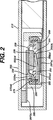
本発明の熱感応電流遮断アセンブリ220は、図1に示すように、リチウムイオン直方体状電池215内に集積される。この種の実施形態において、電流遮断アセンブリは、完全に電池内部に配置され、一方の端部において陽極211に、もう一方の端部において正端子245に電気的に接続される。従って、正常な作動状態においては、陽極211と正端子245との間に電気通路が存在する。電流遮断アセンブリ220の好ましい一実施形態を図2に示す。アセンブリ220は、金属製ケーシング280、金属製エンドキャップ230、形状記憶合金であることが好ましい電流遮断ディスク250、及び、キャップ230の内部表面と接触する金属接点プレート295を有する独立構造型密封ユニットである。図2に示すように、エンドキャップ230は、その表面が外側に膨らむような凹状である。ケーシング280は、図3に示すように開口端とわずかに膨らんだ本体を有するカップ型円形構造である。アセンブリ220は、ディスク250の周辺縁とエンドキャップ230の周辺エッジ縁230(a)との間に、絶縁リング290を備える。アセンブリ220の各構成要素の好ましい構造を図3に示す。電流遮断ディスク250の厚さはその直径又は平均幅に比較して小さく、円形又は円筒形であることが好ましいが、他の形状、例えば卵形又は長円形又は薄い平行六面体又は薄く細長いスラブの形又は平行でなくても差し支えない1対又は複数対の対面する縁をもつプレートであっても差し支えない。この種の構造は、厚さがその長さの約30%未満かつその平均幅の約30%未満であることが好ましい。従って、ここで使用する、詳細には熱感応部材250,350,352と関連して使用するディスクという用語はこのような他の形状が含まれることを意味する。卵形又は長円形のディスクの場合は、平均幅という用語はその主面の最小直径を意味するものとする。
【0013】
ディスク250の厚さは1mm未満であることが望ましく、約0.05ないし0.5mmの間であることが好ましい。図3に最もよく示される電流遮断ディスク250の好ましい実施形態は外側縁258及び中空中心部分257を有する。柔軟で弾性のあるフレキシブル部分255は周辺縁258から中空部分257に内側に向かって突出している。フレキシブル部分255は、その端部255(b)が正極211と正端子245の間の電気通路を完成する接触プレート295に対して第1位置に置かれるようにその表面内でわずかに上向きに曲げる255(a)ことにより図3のように有利に形成される。正常作動中は、電流は、正極211からコネクタタブ287(a)とケーシング280を経て電流遮断ディスク250及び柔軟部分255を通り接触プラグ295とアセンブリエンドキャップ230及びコネクタタブ287(b)を経て正端子245まで流れる。図1から分かるように、電流遮断ディスク250は、抵抗を最小化するために電流がディスク250の厚さ、従って柔軟部分255の厚さを貫いて流れるようにアセンブリ内に配置される。電池215内の温度が所定値を越えると、端部255(b)は下向きに第2位置に向かって偏向し、接触プレート295との接触を遮断し、それによって、電極211と端子245の間の電気通路を遮断し、電池を作動停止(シャットダウン)する。
【0014】
図3において、電流遮断アセンブリ220は、ケーシングの底部表面上に配置されるように電流遮断ディスク250をケーシング280の開口端に挿入することによって容易に組み立てられるように設計されている。ツェナーダイオード600の正の面620は接触プラグ295の内部表面へ接続される。次に、絶縁リング290がディスク250上に挿入され、金属接触プラグ295は堅固なディスク様プラグの形で、形状記憶合金製であることが好ましい突き出た弾性部材255上に位置するまで、絶縁リングに設けられた小孔290(a)を経て挿入される。絶縁グロメット275はエンドキャップ230上に挿入され、エンドキャップ230の内部表面が接触プラグ295の上面に接触するように、これら2つの部品は金属接触プラグ295上に配置される。次に、ケーシング280の周辺縁及び絶縁グロメット275の周辺縁は、エンドキャップ230の周辺縁230(a)上でクリンプされる。クリンプに際しては半径方向の圧力が加えれるので、エンドキャップ230の周辺縁230(a)は、絶縁グロメット275の周辺縁275(a)の内部表面にに噛み込み、エンドキャップ230とケーシング280の間に堅固な密封を形成する。
【0015】
熱電流遮断アセンブリの他の一実施形態、すなわち、アセンブリ320を図6及び7に示す。電流遮断器のこの実施形態は、図4に示すように直方体状電池の端部から、又は、図5に示すように円筒形電池の端部から突き出るように設計されている。この種の実施例形態において、直方体状電池の全体の厚さは少なくとも6mmであることが有利であり、一般に約6ないし20mmの間であれば、アセンブリ320を収容するために十分な厚さである。図5に示すように、電池が円筒形である場合には、アセンブリ320を収容するために、少なくともサイズAAAの電池と同じ大きさの直径であることが望ましい。従って、アセンブリ320は、AAA、AA、A、C、又は、Dサイズの円筒形電池の端部から突き出るか、又は、例えば、電池の直径が約5ないし20mmの間であるように都合よく決定されてもよい。この方法を用いると、アセンブリ320の突出部分、すなわちエンドキャップ325は一方の電池端子を都合よく形成することになる。
【0016】
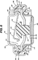
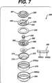
電流遮断アセンブリ320のエンドキャップ325は、図6に示すようにアセンブリ320の上側部分を形成する逆カップ形とアセンブリの下側部分を形成するカップ形本体370の形状であることが望ましい。エンドキャップ325及び本体370は電導性物質で形成される。カップ形本体370のベース372は、電池内圧力が所定値を越えると上方へ(エンドキャップ325の方へ)偏向するように設計された圧力作動ダイアフラムを形成することが好ましい。形状記憶合金又はバイメタルによって有利に構成されるフレキシブル熱感応部材350又は352はカップ370底部内の圧力ダイアフラム372へ近接して配置される。熱感応部材は、図7に示すような曲面をもったディスク350又は352のように円盤形であることが好ましい場合もあり得る。ただし、形状記憶合金又はバイメタル合成材が用いられる場合には、どちらの構造であっても差し支えなく、形状記憶合金が用いられる場合には細長いスラブ又は平行六面体構造352が好ましく、バイメタル合成材が用いられる場合には、円形ディスク350構造であることが好ましい。ディスク350(又はディスク352)は、実質的にエンドキャップ325表面に平行な平面内に所在するようにアセンブリ320内に配置されることが望ましい。電気絶縁ロッド又はプラグ340は、フレキシブル熱感応部材350の最上表面上に配置することができる。アセンブリ320は、本体370の棚部分374上に都合よく配置できる金属支持リング360を含むことが望ましいアセンブリ320は、周辺縁332からディスク330の中空部分333内に伸延する柔軟で弾性のある部材334で構成されるフレキシブルな電導性金属ディスク330を含むことが望ましい。絶縁リング335は、ディスク330の周辺縁332と金属支持リング360の縁362との間に配置される。フレキシブルな導電性ディスク330は、エンドキャップ325の周辺縁327と絶縁リング335の間にはさまれる。絶縁グロメット375は、エンドキャップ325の周辺縁327及びカップ形下側本体370の周辺縁377を囲み、グロメット375はディスク330及び絶縁リング335も囲む。ケーシング380は結果的に絶縁グロメット375を囲む。
【0017】
図7において、電流遮断アセンブリ320は、グロメットの外側表面がケーシング380の内部壁に接触するように先ず絶縁グロメット375をケーシング380に挿入することによって組み立て可能である。熱感応部材350又は352をカップ形本体370へ挿入し、次に、カップ形本体370の棚部分374へ金属支持リング360を挿入することによってサブアセンブリが組み立てられる。プラスチック製可動のロッド340は、部材350に位置するように支持リング360の中心小孔363を通って挿入される。絶縁リング335は、支持リング360上に配置されて、その周辺縁362に接触する。次に、ディスク330は、ディスク330の周辺縁332が絶縁リング335上に位置するように絶縁リング335上に配置される。ツェナーダイオード700の正の面720はエンドキャップ325の内部表面へ接続される。次に、エンドキャップ325の周辺縁327がディスク330の周辺縁332上に載るようにエンドキャップ325がディスク330上に配置される。次に、サブアセンブリは、その中に含まれる絶縁グロメット375と共に、ケーシング380に挿入される。次に、ケーシング380の端部380(a)及びグロメット375の端部375(a)が、サブアセンブリ及びその構成要素が堅固かつ恒久的に所定場所に保持され、グロメット375及び周りのケーシング380によって密封されるように、エンドキャップ325の周辺縁327上でクリンプされる。
【0018】
アセンブリ320は、図8に示すように、例えば、リチウムイオン円筒形電池のような充電可能な円筒形電池400に挿入可能である。アセンブリ320のエンドキャップ325は、電池の端部から突出し、一般に正の端子である電池端子を形成する。同様に、図4に示すように、アセンブリ320は、例えば直方体状リチウムイオン電池500のように、充電可能な直方体状電池に挿入可能である。この種の用途において、エンドキャップ325は電池の端部から突出し、一般に正の端子である電池端子の1つを形成する。円筒形又は直方体状電池が用いられるいずれの場合にも、電池は、随意に追加電流遮断アセンブリ、すなわち、上述の電流遮断アセンブリ220を含むことができる。2つを別々に収納することにより、独立構造型電流遮断アセンブリは、相互に独立して自己作動化する2つの熱感応電流遮断システムを電池に提供する。
【0019】
内部に両方の電流遮断アセンブリ220及び320を含む電池400を図8に示す。図8に示す両方の電流遮断アセンブリ220及び320は、「オン」位置、即ち、電極211から端子エンドキャップ325へ電流が正常に流れることを可能にする位置に在る。電池400がこの種の作動モードにある場合には、電池電極の1つ、例えば電極211と電池端子325の間に電気通路が存在する。正常作動状態において、電流は電極211から接続タブ287(a)、アセンブリ220のケーシング280、接触プラグ295、エンドキャップ230、次に、コネクタタブ287(b)へ流れる。電流はコネクタタブ287(b)からアセンブリ320の下側本体370へ流れる。次に、電流は、本体370から支持リング360、ディスク330の弾性アーム334、ディスク330から端子エンドキャップ325へ流れる。万一電池内部温度が所定値に達した場合には、熱感応弾性部材255が下方に向かって曲がり、それによって、部材255と接触プラグ295の間の電気接続を遮断する。これは、電極211と端子エンドキャップ325の間の電気通路の遮断を実施し、電池を作動停止する。同様に、電池の内部温度が別の所定値に達すると、アセンブリ320の熱感応部材350(又は352)は図6に示す位置に向かって上向きに曲がる。部材350の上向き運動はプラスチック製ロッド340を、ディスク330のフレキシブルかつ弾性あるアーム334に対して上向きに動かす。これは、弾性アーム334に支持リング360との接触を遮断させ、それによって電極211と端子エンドキャップ325の間の電気通路を切断する。電池の内部温度が極めて迅速に上昇した場合には、アセンブリ220の熱感応部材255とアセンブリ320の熱感応部材350(又は352)の両方が作動化され、電極211と端子エンドキャップ325の間の電気通路を2つの場所で無理なく同時に遮断する。これは、確実に電池を即時作動停止させて、安全性を強化し、2つの熱感応部材のうちの1つが動作不良であっても電池は作動停止する。
【0020】
その代りに、電池内の気体圧力が上昇して所定値を超過すると、アセンブリ320のダイアフラム372が上向きに曲がり、プラスチック製ロッド340を弾性アーム334に対して上向きに動かし、弾性アーム334に支持リング360との接触を遮断させる。これは、結果的に、電極211と端子エンドキャップ325の間の電気通路遮断を実施し、それによって電池を作動停止する。ダイアフラム372は電池内部の圧力だけに感応し、必然的に、電池の内部温度とは無関係に作動化される。従って、電池内の気体圧力が電池温度に関係なく所定値に達した場合に、電池が作動停止することを圧力作動ダイアフラム372が保証する。
【0021】
図2及び3に示す電流遮断アセンブリの一実施形態において、内側へ伸延している弾性部材255を備えた熱感応ディスク250又はディスク350又は図6及び図7に示すディスク352は形状記憶合金から成ることが望ましい。形状記憶合金は、例えばニッケル・チタン(Ni−Ti)、銅・亜鉛・アルミニウム(Cu−Zn−Al)、及び、銅・アルミニウム・ニッケル(Cu−Al−Ni)のような公知の記憶合金グループの中から選択可能である。ただし、形状記憶合金ディスク250、又は、ディスク350又は352として最も望ましい合金はニッケル・チタン合金であることが判明した。好ましいニッケル・チタン記憶合金は、Special Metals社からNITINOL合金の商標で入手可能である。ディスク250、又は、ディスク350又は352の弾性部材255はリセット可能記憶合金、即ち、加熱すると変形するが、周囲温度まで冷却すると、外力をかけることなしに、元の形状に戻る合金であっても差し支えない。ただし、形状記憶合金は周囲温度ではリセット可能でないこと、すなわち、その活性化温度まで加熱されると不可逆的に変形することが望ましい。これは、一旦、電池内部が過度の加熱状態を引き起こすと、その電池は再び作動可能にならないことを保証する。従って、ディスク250、359、又は、352は、一旦、作動化されるとリセット不可能なNITINOL合金を用いて作られることが好ましい。好ましい記憶ディスク250は、これから内向きにフレキシブルな部材255が突き出た円形周辺縁258を備えたNITINOL合金の単体として便利に作成可能である。フレキシブル部材255は、折り曲げ線255(a)によって内側脚255(c)から分離された上向きに折れた外側脚255(d)を用いて作成された矩形であることが便利である(図2及び3)。弾性部材255は、幅が約2ないし5mm、長さが3ないし8mm、厚さが約0.05ないし0.5mmであることが望ましい。温度が約60°Cないし120°Cである場合に、脚255(d)は、折り曲げ線255(a)に沿って下方に向かって曲がり、部材255と接触プラグ295の間の接触の遮断を引き起こす。ディスク250の直径は約5ないし15mmの間であることが望ましい。
【0022】
この種の活性化効果を達成するために、記憶ディスク250及び弾性部材255の厚さは、前記部材の抵抗が約5ミリオーム未満であれうような表面部分を備えた約0.05ないし0.5mmの範囲内にあることが有利であることが判明した。前記形状は、正常作動中にその厚さを貫いて電流が流れる場合に、ディスク250の全抵抗を減少させるために厚さを減少させ、良好な接触部分をもつことを可能にするので、ディスク250のための前述の形状、すなわちフレキシブル部分255がそこから内向きに突き出した円形周辺縁を備えた中空ディスクであることが望ましい。形状記憶部材255は約8%を超過する変形歪みを持たないことが望ましい。曲げ角度は約10ないし30度であることが望ましい。即ち、端部255(b)はディスクの平面から約10ないし30度の角度で上向きに曲げられる。これは、活性化温度に達すると、記憶部材255が接触プラグ295から遠のく方向に偏向し、平らになることを可能にする。リチウムイオン電池用に使用する場合には、記憶ディスクに関する前述の好ましい設計では、電池の連続作動状態における電流ドレーンが最大5アンペアであるような全抵抗5ミリオームが結果として得られる。
【0023】
図6及び7に示す電流アセンブリ実施形態において、熱感応部材は、曲がった円形ディスク350の形、又は、薄い曲がった細長いスラブ形にディスク、又は、平行六面体352の形で、形状記憶合金、上述したように好ましくはNITINOL合金によって有利に作ることができる。(ディスク352が薄く細長いスラブの形である場合には、卵形であるか、或いは、1つ又は複数対の平行でない対面する縁を持つ形状であり得る。)ディスク350又は352は、望ましくは約60℃ないし120℃の所定温度に曝した場合、不可逆変形するように作成されることが好ましい。電池の内部温度が所定値を越えた場合には、ディスク又はスラブの湾曲は反転するか、又は、平らになり、プラスチックロッド340にディスク330の弾性アーム334を押圧させる。これは、結果として、上述したように電流を遮断するために、ディスク330と金属支持リング360との間の電気接触の遮断を引き起こす。熱感応ディスク350又は352は、その代りに、バイメタル構成、即ち、熱膨張係数の異なる類似しない金属の2つの層による構成であっても差し支えない。バイメタル構成が用いられる場合には、バイメタルディスク350又はスラブ352の最上層(エンドキャップ325に最も近い層)は、好ましくはニッケル・クロム合金のような高熱膨張金属で構成されても差し支えなく、下に在る層又は底部層は好ましくはニッケル・鉄合金のような低熱膨張金属で構成されても差し支えない。他の適当なバイメタル合成はニッケルとチタンである。この種の実施形態において、ディスク350(又は、ディスク352)は、電池温度が少なくとも60℃まで上昇した場合に作動化し、一般に、約60℃ないし120℃の電池温度で作動化可能である。ディスク350又は352は、−20℃以下の温度を除き、リセットされることのないように、高熱膨張金属層及び低熱膨張金属層を選定することも可能であり、従って、ほとんどの用途において、この種デバイスは単一作動サーモスタットデバイスとして使用される。
【0024】
電流遮断アセンブリ220(図2及び3)において、ケーシング280は、強度と耐腐食性を強化するために、アルミニウム、ステンレス鋼、又は、チタンで形成してもよい。ケーシング280の肉厚は約0.1mmないし0.5mmであることが望ましい。ケーシング280、及び、従ってアセンブリ220の直径は約3ないし15mmであることが望ましく、一般に、直径は約3ないし8mmのあり、深さは約1ないし10mmであり、一般に、約1ないし3mmである。この種の全寸法であるアセンブリ220は、電池容量を著しく減少させるか、又は、電流遮断機能を損なうことなしに、全厚さが約3ないし6mmである非常に薄い直方体状電池に挿入可能である。
【0025】
内部絶縁リング290は、圧縮強度及び温度安定性が比較的高い耐食性サーモプラスチック材料から成ることが望ましい。絶縁リング290用の好ましい物質はCelanese Co.から商標VECTRAポリマとして入手可能な液晶ポリマ、又は、商標VALOXポリマとしてGeneral Electric Plastics社から入手可能なポリエステルである。接触プラグ295は、エンドキャップ230の下面に容易に溶接可能な冷間圧延鋼又はステンレス鋼で形成されることが望ましい。接触プラグ295は、その接触抵抗を小さくするために、銀のような貴金属でめっきしても差し支えない。エンドキャップ230は、強度及び耐食の観点から必要な組合わせを提供するためにステンレス鋼、アルミニウム、又は、チタンで形成されることが望ましく、全直径は約3ないし15mmの間、一般に約4ないし8mmの間であり、全深さは約1mm以下、一般に約0.1ないし1mmの間であることが望ましい。絶縁グロメット275は、厚さが約0.1ないし0.5mmの間、全直径が約3ないし15mmの間、好ましくは約4ないし8mmの間であることが望ましい。グロメット275は、電解質に対して不活性であり、ケーシング280とアセンブリ220の内部構成要素との間に良好な密封性を提供するに充分な弾性を備えた、例えば高密度ポリプロピレンのような耐久性も弾性もある耐食サーモプラスチック材料で形成しても差し支えない。
【0026】
電流遮断アセンブリ320(図6及び7)において、ケーシング380は、強度と耐食性の観点から、ステンレス鋼、又は、ニッケルめっきした冷間圧延鋼によって形成されても差し支えない。ケーシング380の肉厚は約0.1mmないし0.5mmの間であることが望ましい。ケーシング380、ひいてはアセンブリ320は、直径又は全幅が約4ないし15mm、一般に約4ないし8mmの間であり、深さが約1ないし10mm、一般に約3ないし6mmの間であることが好ましい。この種の全寸法のアセンブリ320は、全厚さが約6ないし20mmの直方体状電池、又は、直径が約5ないし20mmの円筒形電池に、電池容量又は電流遮断機能を著しく低下させることなく挿入できる。エンドキャップ325は、一般に、全直径が約4ないし15mmであり、全深さが約0.1ないし1mmである。エンドキャップ325は、十分な強度及び耐食性を提供するために、ステンレス鋼又はニッケルめっき冷間圧延鋼で形成しても差し支えない。フレキシブル導電ディスク330は、直径が約4ないし15mm、厚さが約0.1ないし0.5mmであることが望ましい。それは、その接触抵抗を下げるために例えば金又は銀のような貴金属でめっきした、例えばベリリウム―銅合金又はスプリング鋼のような良好な導電率と強度を備えた弾性金属材料で構成されることが望ましい。ディスク330の弾性アーム334は、矩形であり、幅が約2ないし5mm、長さが約3ないし8mm、厚さが約0.1ないし0.5mmであることが望ましい。
【0027】
絶縁リング335は、圧縮強度及び温度安定性が比較的高い耐食性サーモプラスチック材料で構成されることが望ましい。絶縁リング335用として好ましい材料は、Celanese社からVECTRAポリマという商標で入手可能な液晶ポリマ、又は、General Electric Plastics社からVALOXポリマと称して入手可能なポリエステルである。可動ロッド340は、直径又は幅が約1ないし3mm、長さが1ないし5mmである。ロッド340は本質的に非導電性(高抵抗率材料で形成される)であり、例えば120°C以上の高温度に曝されても熱的に安定していなければならない。ロッド340用の好ましい材料は、Celanese社からVECTRAポリマの商標で入手可能な液晶ポリマである。金属支持リング360は、直径が約4ないし15mm、好ましくは約4ないし8mm、厚さが約0.1ないし1mmであることが望ましい。支持リング360は、十分な強度を提供するために、ステンレス鋼又は冷間圧延鋼から容易に形成可能である。この種材料は、接触抵抗を下げるために金又は銀のような貴金属でめっきしても差し支えない。カップ形本体370の深さは約1ないし3mmであることが望ましい。望ましくはカップ形本体370の基礎を形成する圧力作動ダイアフラム372は、直径が約4ないし15mm、肉厚が約0.1ないし0.5mmである。カップ形本体370及びダイアフラム372は、アルミニウムから容易に形成可能であり、アルミニウムは高い圧力差にさらされると容易かつ恒久的に変形する。絶縁グロメット375は、厚さが約0.1ないし0.5mm、全直径が約4ないし15mmであることが望ましい。グロメット375は、例えば、電解質に対して不活性であり、ケーシング380とアセンブリ320内部構成要素との間に良好な密封性を提供する高密度ポリプロピレンのような耐久性も弾性もある耐食サーモプラスチック材料で形成することができる。
【0028】
本発明は好ましい実施形態に関して記述したが、本発明のコンセプトから逸脱することなしに記述した実施形態の改造が可能であることを理解されたい。従って、本発明が、特定の実施形態に限定されることなく、特許請求の範囲とその均等範囲によって定義されることを意図するものである。
【図面の簡単な説明】
【図1】 完全に直方体状電池内に配置された本発明の電流遮断アセンブリの一実施形態を示す一部切欠斜視図である。
【図2】 図1に示す電池及び電流遮断アセンブリの縦断面図である。
【図3】 図1及び2に示す電流遮断アセンブリの構成要素の分解斜視図である。
【図4】 電池の一端部から突出した状態を示す電流遮断アセンブリの他の一実施形態を伴った直方体状電池の斜視図である。
【図5】 図4に示す電流遮断アセンブリの同じ実施形態を伴った円筒形電池の斜視図である。
【図6】 図4及び5に示す電流遮断アセンブリの縦断面図である。
【図7】 図4、5及び6に示す電流遮断アセンブリの分解斜視図である。
【図8】 図2及び6に示す電流遮断アセンブリの実施形態を含む円筒形電池の縦断面図である。[0001]
The present invention relates to an electrochemical battery current breaker that safely prevents current from passing through the battery upon excessive increase in temperature. The present invention also relates to a battery pressure sensitive current breaker that safely shuts down the battery upon excessive rise in gas pressure therein.
[0002]
Electrochemical batteries, especially batteries with high energy density, for example, where internal lithium or lithium ions are the active material, are leaky or destroyed that can cause damage to the device powered by the battery or the surrounding environment. At risk. In the case of a rechargeable battery, the internal temperature rise of the battery can be attributed to overcharging. Undesirable temperature increases are often accompanied by a corresponding increase in internal gas pressure. This is likely to occur in the case of an external short circuit condition. Furthermore, the internal gas pressure can also increase if the battery is excessively discharged. It would be desirable to attach a safety device to the battery without increasing the cost, size or mass of the battery.
[0003]
This type of battery, in particular a rechargeable battery that utilizes lithium or lithium ions as the active material, is often exposed to leakage or destruction due to the internal temperature rise of the battery with a corresponding pressure increase. This is likely to be caused by overuse conditions such as overcharge or short circuit conditions that can occur during overdischarge. It is also important that these batteries be hermetically sealed to prevent electrolyte solvents from leaking outside and moisture from entering the interior from the outside environment.
[0004]
As mentioned above, self-heating occurs when this type of battery is charged. Charging too quickly or overcharging leads to an increase in temperature. When the temperature exceeds a certain point that varies with the battery chemistry and structure, an undesired and uncontrollable thermal runaway condition begins. In addition, internal pressure may increase due to overheating and the electrolyte may be suddenly released from the battery. It is desirable to initiate controlled ventilation before this condition occurs.
[0005]
Some rechargeable batteries, such as cuboid batteries or small cylindrical batteries for cellular phones, can be very thin. Because this type of battery is small, it has been difficult to incorporate a highly reliable current interruption safety device. However, the need for this type of safety device is great because the battery is close to the consumer when the cellular phone is used normally.
[0006]
The conventional battery design includes an end cap inset that is inserted into a cylindrical casing having an open end after the anode active material and cathode active material of the battery and an appropriate separate material and electrolyte are inserted into the cylindrical case. Is used. The end cap is in electrical contact with one of the anode material or the cathode material, and the exposed portion of the end cap forms one battery terminal. A part of the battery casing forms the other terminal.
[0007]
The present invention deals with one or several current interruption assemblies integrated in a single cell and advantageously applied to primary or secondary (rechargeable) batteries. The end cap assembly of the present invention can be used to cause the battery to overheat and to increase the pressure in the battery when exposed to high temperatures, to perform excessive or inappropriate charging or discharging, or To overcome the danger of short circuiting, use it for rechargeable batteries such as lithium ion, nickel metal hydride, nickel cadmium, or other rechargeable batteries.
[0008]
The present invention, in one aspect, is directed to a current interruption mechanism for thin cuboid batteries or small diameter cylindrical batteries. A small heat sensitive current interrupt assembly is placed in the battery. The current interrupt assembly is preferably a stand-alone sealing device that is advantageously manufactured separately and can be inserted into the battery as a separate unit during battery assembly. When the battery interior overheats and exceeds a predetermined temperature, the heat sensitive current interrupt mechanism in the independent assembly operates to interrupt the current and prevent current from flowing through the battery. The current interrupt mechanism includes a heat sensitive member that is preferably a flexible disk made of a shape memory metal alloy having a curved surface. In the normal operation of the battery, the shape memory alloy disk preferably forms a part of an electric path between one battery electrode and a terminal to which the electrode is connected. When the temperature inside the battery reaches a predetermined value, the shape memory disk is deflected, the electric path between the electrode and the terminal is cut off, and the battery is stopped (shut down). A diode, preferably a zener diode, may be disposed within the current interrupt assembly in proximity to the shape memory disk. The zener diode is electrically connected in parallel with the battery terminal. When a battery is inadvertently overcharged, charged for a long time, or charged with an excessive voltage, it heats the diode and, consequently, deflects the shape memory disk to block the electrical path, To stop the battery.
[0009]
In another aspect of the present invention, the current interrupt assembly is an independent unit comprised of both a heat sensitive current interrupt mechanism and a pressure activated current interrupt mechanism. The current interrupt assembly has an exposed end cap plate that functions as a battery terminal. When the assembly is applied to a battery and the battery is operating normally, the end cap plate is in electrical communication with the battery electrode (anode or cathode). The current interrupt mechanism comprises a heat sensitive flexible member that may be in physical communication with a flexible conductive member, preferably made of a shape memory metal alloy in the form of a curved disk or bimetal. The physical continuity between the heat sensitive member and the flexible conductive member may be achieved by a non-conductive movable rod disposed between these two elements. When the battery is operating normally, the flexible conductive member forms part of the electrical path between one of the battery electrodes and the end cap (terminal). When the temperature in the battery reaches a predetermined value, the heat sensitive member deflects and presses the flexible conductive member by the non-conductive movable rod to deflect it, and as a result, the electric path between the electrode and the terminal is blocked. Furthermore, it is desirable that the assembly includes a pressure activated current interrupt mechanism that preferably includes a pressure activated metal diaphragm. The diaphragm forms part of the current interrupt assembly housing and preferably deflects when the cell internal pressure exceeds a predetermined level. The deflection of the diaphragm causes a blockage of the electrical path between the battery electrode and the corresponding terminal, thereby deactivating the battery.
[0010]
In another aspect, the battery may include both of the two types of independent current blocking assemblies. That is, one includes a heat sensitive current interrupt mechanism and the other includes both a heat sensitive current interrupt mechanism mechanism and a pressure activated current interrupt mechanism. This gives the battery a multiple independent current interrupt safety function. For example, if the battery diameter is large enough to accommodate both current interrupt assemblies, such as when the battery diameter or overall thickness is between about 5 and 20 mm. The design can be used advantageously. In one such embodiment, a current interrupt assembly having only a heat sensitive current interrupt mechanism can be advantageously placed completely inside the battery so as to be in close proximity to the hottest part of the battery. A diode, preferably a Zener diode, can be included in one or both such independent current interrupt assemblies and be electrically connected in parallel with the battery terminals.
[0011]
In a preferred embodiment, the thermally sensitive
[0012]
The heat-sensitive
[0013]
The thickness of the
[0014]
In FIG. 3, the current interrupt
[0015]
Another embodiment of a thermal current interrupt assembly, ie,
[0016]
The
[0017]
In FIG. 7, the current interrupt
[0018]
The
[0019]
A
[0020]
Instead, when the gas pressure in the battery rises and exceeds a predetermined value, the
[0021]
In one embodiment of the current interrupt assembly shown in FIGS. 2 and 3, the heat
[0022]
In order to achieve this type of activation effect, the thickness of the
[0023]
In the current assembly embodiment shown in FIGS. 6 and 7, the heat sensitive member is a shape memory alloy, as described above, in the form of a curved
[0024]
In the current interrupt assembly 220 (FIGS. 2 and 3), the
[0025]
The inner
[0026]
In the current interruption assembly 320 (FIGS. 6 and 7), the
[0027]
The insulating
[0028]
Although the present invention has been described with reference to preferred embodiments, it is to be understood that modifications of the described embodiments are possible without departing from the inventive concept. Therefore, it is intended that this invention be defined not by the specific embodiments but by the claims and their equivalents.
[Brief description of the drawings]
FIG. 1 is a partially cutaway perspective view showing one embodiment of the current interrupt assembly of the present invention fully disposed within a rectangular parallelepiped battery.
FIG. 2 is a longitudinal sectional view of the battery and current interrupt assembly shown in FIG.
3 is an exploded perspective view of the components of the current interrupt assembly shown in FIGS. 1 and 2. FIG.
FIG. 4 is a perspective view of a rectangular parallelepiped battery with another embodiment of a current interrupting assembly showing a state protruding from one end of the battery.
FIG. 5 is a perspective view of a cylindrical battery with the same embodiment of the current interrupt assembly shown in FIG.
6 is a longitudinal cross-sectional view of the current interrupt assembly shown in FIGS. 4 and 5. FIG.
7 is an exploded perspective view of the current interrupt assembly shown in FIGS. 4, 5 and 6. FIG.
8 is a longitudinal cross-sectional view of a cylindrical battery that includes the embodiment of the current interrupt assembly shown in FIGS. 2 and 6. FIG.
Claims (7)
前記電気化学的電池(215)は、正端子(245)と、負端子(246)と、1枚の陽極材料(211)と、1枚の陰極材料(213)とをさらに備え、The electrochemical cell (215) further comprises a positive terminal (245), a negative terminal (246), one anode material (211), and one cathode material (213),
前記第1の電流遮断アセンブリ(320)は、カップ形本体(370)と、前記カップ形本体(370)内の第1のチャンバと、エンドキャップ(325)とを有し、The first current interrupt assembly (320) has a cup-shaped body (370), a first chamber in the cup-shaped body (370), and an end cap (325);
前記エンドキャップ(325)は、前記第1の電流遮断アセンブリ(320)内の電気的導電通路を介して前記電極材料(211,213)の一つに電気的に接続され、The end cap (325) is electrically connected to one of the electrode materials (211, 213) via an electrically conductive path in the first current interrupt assembly (320),
前記第1の電流遮断アセンブリ(320)はその内部に、前記第1の電流遮断アセンブリ(320)内における前記電気的導電通路の一部を形成する、フレキシブルな電導性金属ディスク(330)を有し、The first current interrupt assembly (320) has a flexible conductive metal disk (330) formed therein that forms a portion of the electrically conductive path within the first current interrupt assembly (320). And
前記第1の電流遮断アセンブリ(320)は、所定の温度レベルが達成されたときに電流が前記電気化学的電池(215)内を流れないようにする熱感応部材(350)をさらに有し、The first current interrupt assembly (320) further comprises a heat sensitive member (350) that prevents current from flowing through the electrochemical cell (215) when a predetermined temperature level is achieved;
前記熱感応部材(350)は湾曲した面を有する形状記憶合金部材を有し、The heat sensitive member (350) has a shape memory alloy member having a curved surface,
前記第1の電流遮断アセンブリ(320)は、前記形状記憶合金部材の面曲率の変化に対応して前記フレキシブルな電導性金属ディスク(330)が動くようにする、電気絶縁ロッド(340)をさらに有し、The first current interrupt assembly (320) further includes an electrically insulating rod (340) that allows the flexible conductive metal disk (330) to move in response to a change in surface curvature of the shape memory alloy member. Have
前記形状記憶合金部材を、前記電気化学的電池(215)の温度が所定の温度に達したとき、前記形状記憶合金部材が変形してその表面の少なくとも一部の曲率を変え、前記フレキシブルな電導性金属ディスク(330)を動かして前記エンドキャップ(325)と前記電極材料(211,213)との間の前記電気的導電通路を遮断する、ものとして構成し、それによって前記電気化学的電池(215)を電流が流れるのを阻止し、When the temperature of the electrochemical cell (215) reaches a predetermined temperature, the shape memory alloy member is deformed to change the curvature of at least a part of the surface thereof, so that the flexible conductive The electrically conductive metal disk (330) is moved to block the electrically conductive path between the end cap (325) and the electrode material (211, 213), whereby the electrochemical cell ( 215) prevents current from flowing,
前記第1の電流遮断アセンブリ(320)は、前記カップ形本体(370)の一部を形成し前記第1の電流遮断アセンブリ(320)の外側に露出する面を有する、圧力ダイアフラム(372)を有し、前記フレキシブルな電導性金属ディスク(330)を、前記圧力ダイアフラム(372)の変形に対応して動く、ものとして構成し、The first current interrupt assembly (320) includes a pressure diaphragm (372) having a surface that forms part of the cup-shaped body (370) and is exposed to the outside of the first current interrupt assembly (320). The flexible conductive metal disk (330) is configured to move in response to deformation of the pressure diaphragm (372);
前記圧力ダイアフラム(372)を、前記圧力ダイアフラム(372)の露出された側のガス圧が上がるとき、前記圧力ダイアフラム(372)が前記第1の電流遮断アセンブリ(320)の内側に向かって変形して、前記電気絶縁ロッド(340)が前記フレキシブルな電導性金属ディスク(330)を押すようになる、ものとして構成し、それによって前記第1の電流遮断アセンブリ(320)内の前記電気的導電通路を遮断し、When the gas pressure on the exposed side of the pressure diaphragm (372) increases, the pressure diaphragm (372) deforms toward the inside of the first current interrupt assembly (320). The electrically insulating rod (340) is adapted to push the flexible conductive metal disk (330), whereby the electrically conductive path in the first current interrupt assembly (320). Shut off
前記第2の電流遮断アセンブリ(220)は、ケーシング(280)と、前記ケーシング(280)内の第2のチャンバと、前記ケーシング(280)を密封するエンドキャップ(230)とを有し、The second current interrupt assembly (220) includes a casing (280), a second chamber in the casing (280), and an end cap (230) that seals the casing (280);
前記第2の電流遮断アセンブリ(220)は、前記ケーシング(280)と前記第2の電流遮断アセンブリ(220)の前記エンドキャップ(230)との間に自己を通る電気的導電通路を有し、The second current interrupt assembly (220) has an electrically conductive passage therethrough between the casing (280) and the end cap (230) of the second current interrupt assembly (220);
前記第2の電流遮断アセンブリ(220)は完全に前記電気化学的電池(215)の内部に配置され、The second current interrupt assembly (220) is disposed entirely within the electrochemical cell (215);
前記第2の電流遮断アセンブリ(220)は、前記第2のチャンバ内に、前記第2の電流遮断アセンブリ(220)内の前記電気的導電通路を電流が通るのを防ぐ、熱感応部材(250)を有し、The second current blocking assembly (220) prevents heat from passing through the electrically conductive path in the second current blocking assembly (220) into the second chamber. )
前記熱感応部材(250)は形状記憶合金部材を有し、前記形状記憶合金部材は、前記第2の電流遮断アセンブリ(220)内の温度が所定のレベルに達した時に作動可能であり前記第2の電流遮断アセンブリ(220)を通る前記電気的導電通路を遮断する、ものとして構成され、それによって前記電気化学的電池(215)の動作を終了させる、The heat sensitive member (250) includes a shape memory alloy member, the shape memory alloy member is operable when a temperature in the second current interrupt assembly (220) reaches a predetermined level, and Interrupting the electrically conductive path through two current interrupt assemblies (220), thereby terminating the operation of the electrochemical cell (215);
ことを特徴とする、電気化学的電池。An electrochemical battery characterized by the above.
前記ディスクは所定の温度に達したときに自己の厚さ方向に曲がる曲面を有する、
ことを特徴とする、請求項1に記載の電気化学的電池。The shape memory alloy member in the current interrupt assembly comprises a shape memory alloy disk;
The disk has a curved surface that bends in its own thickness direction when a predetermined temperature is reached,
The electrochemical cell according to claim 1, wherein:
前記周辺縁(332)は前記第1の電流遮断アセンブリ(320)内の絶縁リング(335)の表面に置かれ、前記弾性アーム(334)は前記形状記憶合金部材の変形に対応して移動可能であり、これにより前記電気的導電通路を遮断することを特徴とする、請求項1乃至5のいずれかに記載の電気化学的電池。The peripheral edge (332) is placed on the surface of an insulating ring (335) in the first current interrupt assembly (320), and the elastic arm (334) is movable in response to deformation of the shape memory alloy member. The electrochemical cell according to claim 1, wherein the electrically conductive path is blocked.
Applications Claiming Priority (3)
| Application Number | Priority Date | Filing Date | Title |
|---|---|---|---|
| US08/916,627 US6083639A (en) | 1997-08-22 | 1997-08-22 | Current interrupter for electrochemical cells |
| US08/916,627 | 1997-08-22 | ||
| PCT/US1998/017151 WO1999010941A1 (en) | 1997-08-22 | 1998-08-19 | Current interrupter for electrochemical cells |
Publications (3)
| Publication Number | Publication Date |
|---|---|
| JP2001514436A JP2001514436A (en) | 2001-09-11 |
| JP2001514436A5 JP2001514436A5 (en) | 2006-01-05 |
| JP4391016B2 true JP4391016B2 (en) | 2009-12-24 |
Family
ID=25437587
Family Applications (1)
| Application Number | Title | Priority Date | Filing Date |
|---|---|---|---|
| JP2000508150A Expired - Fee Related JP4391016B2 (en) | 1997-08-22 | 1998-08-19 | Current breaker for electrochemical battery |
Country Status (13)
| Country | Link |
|---|---|
| US (2) | US6083639A (en) |
| EP (1) | EP1018175B1 (en) |
| JP (1) | JP4391016B2 (en) |
| CN (1) | CN1268254A (en) |
| AR (2) | AR014109A1 (en) |
| AT (1) | ATE291778T1 (en) |
| AU (1) | AU8914298A (en) |
| BR (1) | BR9811338B1 (en) |
| CA (1) | CA2301085A1 (en) |
| DE (1) | DE69829491T2 (en) |
| TW (1) | TW434926B (en) |
| WO (1) | WO1999010941A1 (en) |
| ZA (2) | ZA987501B (en) |
Families Citing this family (41)
| Publication number | Priority date | Publication date | Assignee | Title |
|---|---|---|---|---|
| US5844464A (en) * | 1997-11-24 | 1998-12-01 | Therm-O-Disc, Incorporated | Thermal switch |
| US6210824B1 (en) * | 1998-01-15 | 2001-04-03 | Texas Instruments Incorporated | Current interrupt apparatus for electrochemical cells |
| JP2954147B1 (en) * | 1998-03-20 | 1999-09-27 | 日本電気株式会社 | Explosion-proof secondary battery |
| US6241349B1 (en) * | 1999-01-28 | 2001-06-05 | Hewlett-Packard Company | High-durability ink containment unit for use in an ink delivery system |
| US6342826B1 (en) * | 1999-08-11 | 2002-01-29 | Therm-O-Disc, Incorporated | Pressure and temperature responsive switch assembly |
| US6489879B1 (en) * | 1999-12-10 | 2002-12-03 | National Semiconductor Corporation | PTC fuse including external heat source |
| WO2002035618A1 (en) | 2000-10-20 | 2002-05-02 | Rayovac Corporation | Method and apparatus for regulating charging of electrochemical cells |
| US7655001B2 (en) * | 2001-03-23 | 2010-02-02 | Petrakis Dennis N | Temperature responsive systems |
| JP3716773B2 (en) | 2001-09-27 | 2005-11-16 | ソニー株式会社 | Battery pack and thermostat used therefor |
| US6730431B2 (en) | 2001-12-19 | 2004-05-04 | Alcatel | Battery having tube collapsing vent system and overcharge protection |
| DE10313860A1 (en) * | 2002-03-28 | 2003-10-30 | Denso Corp | Fuel pump with brushes and process for their manufacture |
| KR100528915B1 (en) * | 2003-05-26 | 2005-11-16 | 삼성에스디아이 주식회사 | Secondary battery |
| TW200525854A (en) * | 2003-08-15 | 2005-08-01 | Rovcal Inc | Method and apparatus for charging electrochemical cells |
| US20050253561A1 (en) * | 2004-05-11 | 2005-11-17 | Tibbs Bobby L | Temperature sensitive charging of batteries with simple chargers |
| US7579105B2 (en) | 2005-02-18 | 2009-08-25 | The Gillette Company | End cap assembly and vent for high power cells |
| CN101305481B (en) * | 2005-09-02 | 2011-01-12 | A123系统公司 | Battery cell design and method of its construction |
| US8084158B2 (en) | 2005-09-02 | 2011-12-27 | A123 Systems, Inc. | Battery tab location design and method of construction |
| US7763375B2 (en) * | 2006-05-24 | 2010-07-27 | Eveready Battery Company, Inc. | Current interrupt device for batteries |
| US20080241645A1 (en) * | 2007-03-26 | 2008-10-02 | Pinnell Leslie J | Lithium ion secondary batteries |
| US20080248375A1 (en) * | 2007-03-26 | 2008-10-09 | Cintra George M | Lithium secondary batteries |
| US20080240480A1 (en) * | 2007-03-26 | 2008-10-02 | Pinnell Leslie J | Secondary Batteries for Hearing Aids |
| US20080254343A1 (en) * | 2007-04-16 | 2008-10-16 | Eveready Battery Company, Inc. | Electrochemical cell with thermal current interrupting switch |
| US8236441B2 (en) | 2007-07-24 | 2012-08-07 | A123 Systems, Inc. | Battery cell design and methods of its construction |
| KR101230994B1 (en) * | 2010-12-03 | 2013-02-07 | 기아자동차주식회사 | Large-sized Battery |
| DE102011015829A1 (en) | 2011-04-01 | 2012-10-04 | Li-Tec Battery Gmbh | Electrochemical energy storage cell with current interruption device |
| DE102012200862A1 (en) * | 2012-01-23 | 2013-07-25 | Robert Bosch Gmbh | Battery production by spin coating |
| KR101349013B1 (en) | 2012-04-23 | 2014-01-10 | 현대자동차주식회사 | Housing for electric and electronic components using shape memory material |
| CN106256030B (en) * | 2014-05-30 | 2020-12-29 | 松下知识产权经营株式会社 | Cylindrical lithium ion secondary battery |
| KR102382052B1 (en) * | 2015-03-02 | 2022-04-01 | 삼성에스디아이 주식회사 | Rechargeable battery module |
| US10128486B2 (en) | 2015-03-13 | 2018-11-13 | Purdue Research Foundation | Current interrupt devices, methods thereof, and battery assemblies manufactured therewith |
| KR102528490B1 (en) * | 2015-10-30 | 2023-05-04 | 엘지이노텍 주식회사 | camara module for lens heater with temperature control |
| WO2017163999A1 (en) * | 2016-03-25 | 2017-09-28 | 三洋電機株式会社 | Cylindrical battery |
| EP3336925A1 (en) * | 2016-12-14 | 2018-06-20 | Lithium Energy and Power GmbH & Co. KG | Cell connecting element |
| CN110612620A (en) | 2017-02-01 | 2019-12-24 | 24M技术公司 | System and method for improving safety features in electrochemical cells |
| US11476551B2 (en) | 2017-07-31 | 2022-10-18 | 24M Technologies, Inc. | Current interrupt devices using shape memory materials |
| US10854869B2 (en) | 2017-08-17 | 2020-12-01 | 24M Technologies, Inc. | Short-circuit protection of battery cells using fuses |
| CN209329677U (en) * | 2019-01-15 | 2019-08-30 | 常州市派腾电子技术服务有限公司 | Overheating protection circuit, electronic cigarette and electronic equipment |
| KR102537762B1 (en) * | 2020-02-07 | 2023-05-26 | 닝더 엠프렉스 테크놀로지 리미티드 | Button battery and electric apparatus provided with button battery |
| WO2021172234A1 (en) * | 2020-02-28 | 2021-09-02 | パナソニックIpマネジメント株式会社 | Power storage device |
| EP4162544A1 (en) | 2020-06-04 | 2023-04-12 | 24M Technologies, Inc. | Electrochemical cells with one or more segmented current collectors and methods of making the same |
| US20230147262A1 (en) * | 2021-11-09 | 2023-05-11 | Hand Held Products, Inc. | Battery fault detection assemblies |
Family Cites Families (28)
| Publication number | Priority date | Publication date | Assignee | Title |
|---|---|---|---|---|
| US3373057A (en) * | 1965-10-24 | 1968-03-12 | Texas Instruments Inc | Battery having an automatic circuit breaker therein |
| US3617386A (en) * | 1970-04-30 | 1971-11-02 | Esb Inc | Sealed cell construction |
| US4035552A (en) * | 1976-07-23 | 1977-07-12 | Gte Laboratories Incorporated | Electrochemical cell |
| GB2206734B (en) * | 1987-06-27 | 1991-04-24 | Haden D H Ltd | Thermally responsive electrical device |
| DE3721754A1 (en) * | 1987-07-01 | 1989-01-12 | Asea Brown Boveri | BRIDGE ELEMENT FOR SECURING BATTERY CELLS |
| US4855195A (en) * | 1988-07-11 | 1989-08-08 | Eveready Battery Company, Inc. | Electrochemical cell with internal circuit interrupter |
| US4992339A (en) * | 1990-03-14 | 1991-02-12 | Eveready Battery Company, Inc. | Electrochemical cell with circuit disconnect device |
| US4975341A (en) * | 1990-04-03 | 1990-12-04 | Eveready Battery Company, Inc. | Electrochemical cell with circuit disconnect device |
| JP2961853B2 (en) * | 1990-09-26 | 1999-10-12 | ソニー株式会社 | Battery protection device |
| JPH05234614A (en) * | 1992-02-20 | 1993-09-10 | Nippon Telegr & Teleph Corp <Ntt> | Cylindrical battery |
| JPH05266878A (en) * | 1992-03-23 | 1993-10-15 | Nippon Telegr & Teleph Corp <Ntt> | Cylindrical secondary battery |
| US5268664A (en) * | 1993-01-25 | 1993-12-07 | Portage Electric Products, Inc. | Low profile thermostat |
| DE4345350C2 (en) * | 1993-10-30 | 1997-05-22 | Hofsaes Geb Zeitz Ulrika | Temp. dependent switch |
| DE4409268C1 (en) * | 1994-03-18 | 1995-06-22 | Daimler Benz Ag | Electrochemical storage battery for electric vehicle |
| US5567539A (en) * | 1994-05-23 | 1996-10-22 | Fuji Photo Film Co., Ltd. | Non-aqueous secondary cell |
| JPH08185849A (en) * | 1994-12-27 | 1996-07-16 | Fuji Elelctrochem Co Ltd | Electrochemical element having explosion-proof safety device |
| EP0739047A3 (en) * | 1995-04-21 | 1999-04-07 | Wako Electronics Co., Ltd. | Safety device for use in secondary battery |
| JPH09106803A (en) * | 1995-10-09 | 1997-04-22 | Wako Denshi Kk | Safety apparatus for battery |
| KR0158845B1 (en) * | 1995-07-28 | 1999-02-18 | 배순훈 | An over-load preventing device of lithium battery |
| JP3557748B2 (en) * | 1995-09-21 | 2004-08-25 | 宇部興産株式会社 | Sealed non-aqueous secondary battery |
| JPH09106804A (en) * | 1995-10-09 | 1997-04-22 | Wako Denshi Kk | Safety apparatus for battery |
| US5776790A (en) * | 1996-02-28 | 1998-07-07 | International Business Machines Corporation | C4 Pb/Sn evaporation process |
| US5750277A (en) * | 1996-04-10 | 1998-05-12 | Texas Instruments Incorporated | Current interrupter for electrochemical cells |
| US5691073A (en) * | 1996-04-10 | 1997-11-25 | Duracell Inc. | Current interrupter for electrochemical cells |
| US5879832A (en) * | 1996-10-02 | 1999-03-09 | Duracell Inc. | Current interrupter for electrochemical cells |
| US5708350A (en) * | 1996-08-09 | 1998-01-13 | Eveready Battery Company, Inc. | Recharging method and temperature-responsive overcharge protection circuit for a rechargeable battery pack having two terminals |
| JPH1074500A (en) * | 1996-08-30 | 1998-03-17 | Sanyo Electric Co Ltd | Sealed battery and its manufacture |
| CA2233390A1 (en) * | 1997-05-02 | 1998-11-02 | William F. Quinn | Thermal switch assembly |
-
1997
- 1997-08-22 US US08/916,627 patent/US6083639A/en not_active Expired - Fee Related
- 1997-11-06 US US08/965,248 patent/US5998051A/en not_active Expired - Fee Related
-
1998
- 1998-08-19 CA CA002301085A patent/CA2301085A1/en not_active Abandoned
- 1998-08-19 AU AU89142/98A patent/AU8914298A/en not_active Abandoned
- 1998-08-19 ZA ZA987501A patent/ZA987501B/en unknown
- 1998-08-19 JP JP2000508150A patent/JP4391016B2/en not_active Expired - Fee Related
- 1998-08-19 BR BRPI9811338-0A patent/BR9811338B1/en not_active IP Right Cessation
- 1998-08-19 CN CN98808394A patent/CN1268254A/en active Pending
- 1998-08-19 DE DE69829491T patent/DE69829491T2/en not_active Expired - Lifetime
- 1998-08-19 ZA ZA987495A patent/ZA987495B/en unknown
- 1998-08-19 EP EP98940987A patent/EP1018175B1/en not_active Expired - Lifetime
- 1998-08-19 AT AT98940987T patent/ATE291778T1/en not_active IP Right Cessation
- 1998-08-19 WO PCT/US1998/017151 patent/WO1999010941A1/en active IP Right Grant
- 1998-08-20 AR ARP980104116A patent/AR014109A1/en unknown
- 1998-08-20 AR ARP980104117A patent/AR013946A1/en not_active Application Discontinuation
- 1998-09-08 TW TW087113854A patent/TW434926B/en active
Also Published As
| Publication number | Publication date |
|---|---|
| AR014109A1 (en) | 2001-02-07 |
| CN1268254A (en) | 2000-09-27 |
| ZA987501B (en) | 1999-02-23 |
| US5998051A (en) | 1999-12-07 |
| EP1018175A1 (en) | 2000-07-12 |
| DE69829491D1 (en) | 2005-04-28 |
| AU8914298A (en) | 1999-03-16 |
| BR9811338B1 (en) | 2009-05-05 |
| DE69829491T2 (en) | 2006-05-11 |
| ZA987495B (en) | 1999-02-22 |
| WO1999010941A1 (en) | 1999-03-04 |
| AR013946A1 (en) | 2001-01-31 |
| CA2301085A1 (en) | 1999-03-04 |
| TW434926B (en) | 2001-05-16 |
| EP1018175B1 (en) | 2005-03-23 |
| US6083639A (en) | 2000-07-04 |
| ATE291778T1 (en) | 2005-04-15 |
| JP2001514436A (en) | 2001-09-11 |
| BR9811338A (en) | 2000-09-12 |
Similar Documents
| Publication | Publication Date | Title |
|---|---|---|
| JP4391016B2 (en) | Current breaker for electrochemical battery | |
| EP0974168B1 (en) | Current interrupter for electrochemical cells | |
| EP0925611B1 (en) | Current interrupter for electrochemical cells | |
| US5879832A (en) | Current interrupter for electrochemical cells | |
| US5691073A (en) | Current interrupter for electrochemical cells | |
| JP4391015B2 (en) | Current breaker for electrochemical battery | |
| MXPA00001809A (en) | Current interrupter for electrochemical cells | |
| RU2195749C2 (en) | Galvanic-cell end plug assembly and galvanic cell | |
| MXPA00001797A (en) | Current interrupter for electrochemical cells | |
| MXPA99009232A (en) | Current interrupter for electrochemical cells | |
| MXPA99009231A (en) | Current interrupter for electrochemical cells | |
| MXPA98008383A (en) | Current switch for electroquimi cells |
Legal Events
| Date | Code | Title | Description |
|---|---|---|---|
| A521 | Request for written amendment filed |
Free format text: JAPANESE INTERMEDIATE CODE: A523 Effective date: 20050819 |
|
| A621 | Written request for application examination |
Free format text: JAPANESE INTERMEDIATE CODE: A621 Effective date: 20050819 |
|
| A711 | Notification of change in applicant |
Free format text: JAPANESE INTERMEDIATE CODE: A712 Effective date: 20080815 |
|
| A131 | Notification of reasons for refusal |
Free format text: JAPANESE INTERMEDIATE CODE: A131 Effective date: 20090217 |
|
| A601 | Written request for extension of time |
Free format text: JAPANESE INTERMEDIATE CODE: A601 Effective date: 20090518 |
|
| A602 | Written permission of extension of time |
Free format text: JAPANESE INTERMEDIATE CODE: A602 Effective date: 20090525 |
|
| A521 | Request for written amendment filed |
Free format text: JAPANESE INTERMEDIATE CODE: A523 Effective date: 20090817 |
|
| TRDD | Decision of grant or rejection written | ||
| A01 | Written decision to grant a patent or to grant a registration (utility model) |
Free format text: JAPANESE INTERMEDIATE CODE: A01 Effective date: 20090908 |
|
| A01 | Written decision to grant a patent or to grant a registration (utility model) |
Free format text: JAPANESE INTERMEDIATE CODE: A01 |
|
| A61 | First payment of annual fees (during grant procedure) |
Free format text: JAPANESE INTERMEDIATE CODE: A61 Effective date: 20091007 |
|
| FPAY | Renewal fee payment (event date is renewal date of database) |
Free format text: PAYMENT UNTIL: 20121016 Year of fee payment: 3 |
|
| R150 | Certificate of patent or registration of utility model |
Free format text: JAPANESE INTERMEDIATE CODE: R150 |
|
| LAPS | Cancellation because of no payment of annual fees |