JP4390938B2 - Wireless access system - Google Patents
Wireless access system Download PDFInfo
- Publication number
- JP4390938B2 JP4390938B2 JP35182899A JP35182899A JP4390938B2 JP 4390938 B2 JP4390938 B2 JP 4390938B2 JP 35182899 A JP35182899 A JP 35182899A JP 35182899 A JP35182899 A JP 35182899A JP 4390938 B2 JP4390938 B2 JP 4390938B2
- Authority
- JP
- Japan
- Prior art keywords
- signal
- wireless device
- transmission
- adjustment value
- timing adjustment
- Prior art date
- Legal status (The legal status is an assumption and is not a legal conclusion. Google has not performed a legal analysis and makes no representation as to the accuracy of the status listed.)
- Expired - Fee Related
Links
Images


Landscapes
- Mobile Radio Communication Systems (AREA)
Abstract
Description
【0001】
【発明の属する技術分野】
本発明は、無線を利用して高速回線を利用者に提供する加入者無線アクセスシステムに係り、特に、基地局装置からの距離による伝播遅延に対する送受信タイミングを加入者局装置に容易に設定する無線アクセスシステムに関する。
【0002】
【従来の技術】
次世代の情報通信基盤整備を目的とし、2010年を目標に加入者系光ファイバ網の全国整備が進められる中、加入者系光ファイバ網の補完的利用や地域網整備の早期推進などの目的で、無線を利用して高速回線を加入者へ提供する加入者無線アクセスシステム(FWS:Fixed Wireless Access/単に「無線アクセスシステム」と呼ぶ)への要求が膨らんでいる。
【0003】
無線アクセスシステムには、企業を対象としたビル間通信によるP−P(Point-Point)方式と、一般住宅や小規模オフィス(SOHO:Small Office Home Office)を対象としたP−MP(Point-MultiPoint)方式が考えられている。
P−MP方式の無線アクセスシステムでは、一つの無線基地局と、無線回線で接続する複数の加入者局で構成される。
【0004】
イーサネットを介して交換網と接続された基地局装置と、無線回線で接続する加入者局装置で構成される無線アクセスシステムにおいては、新規に一つの加入者局装置を設置する場合に、基地局装置からの距離による伝播遅延に対する送受信タイミング(ディレイ)を加入者局装置に設定する必要がある。
【0005】
具体的に図4を用いて説明する。図4は、基地局装置で送信される無線フレームと加入者局装置で受信される無線フレームを示す説明図である。
図4に示すように、基地局装置は、同期信号とデータ信号を含む無線フレームを加入者局装置に送信する。加入者局装置では、基地局装置との距離があるため、伝播遅延して受信される。但し、同期信号には加入者IDに対するディレイ値が含まれており、加入者局装置は、自己の加入者IDに対するディレイ値に基づいて送受信タイミングを調整することになる。
【0006】
尚、加入者局を設置する際に、予め基地局への送信タイミングの調整値を設定する従来技術として、平成11年(1999年)6月18日公開の特開平11−164353号公報「無線通信システムにおける送信タイミング調整方式」(出願人:日本電気株式会社、発明者:久保庭修)がある。
この技術は、通信を試みた基地局から応答がない場合に、送信タイミング設定値の変更が必要と判定し、送信タイミング設定メモリに格納されている設定値を変更する操作を基地局からの応答が得られるまで繰り返すものである。
【0007】
【発明が解決しようとする課題】
しかしながら、従来の無線アクセスシステムでは、机上で計算した設定値を加入者局装置に施しても、基地局装置との同期を確立できることになることは少なく、実際にフィールドでの通信状態をモニタしながらの微調整が必要になり、送受信タイミングを加入者局装置に設定するのが難しいという問題点があった。
また、上記従来技術のように、基地局からの応答を得られるまで、送信タイミング値の変更を繰り返す方法では、最適な送信タイミングを設定するまでに時間がかかるという問題点があった。
【0008】
本発明は上記実情に鑑みて為されたもので、基地局装置からの距離による伝播遅延に対する送受信タイミングを加入者局装置に容易に設定できる無線アクセスシステムを提供することを目的とする。
【0009】
【課題を解決するための手段】
上記従来例の問題点を解決するための本発明は、無線アクセスシステムにおいて、第1の無線装置と第2の無線装置との間で送受されるフレームフォーマットは、特定信号と、特定信号に続く応答信号と、応答信号に続き運用時に使用される運用時使用信号と、運用時使用信号に続く送信タイミング調整値通知用信号とから成り、第1の無線装置が、第2の無線装置に対して新規加入の設定を行う際に、特定信号を第2の無線装置に送信し、第2の無線装置から送信された応答信号を受信し、当該応答信号に基づいてタイミングずれを測定して運用時使用信号の後に第2の無線装置に当該タイミングずれを補正するタイミング調整値を含む送信タイミング調整値通知用信号を送信し、第2の無線装置が、第1の無線装置から送信された送信タイミング調整値通知用信号に含まれるタイミング調整値に基づいて送受信のタイミングを設定し、当該送受信のタイミングに基づいて応答信号を送信することを特徴としており、伝播遅延に対する送信タイミングを加入者局装置に容易に設定できる。
【0010】
また、本発明は、上記無線アクセスシステムにおいて、タイミング調整値の通知を受けた加入者局装置は、当該値を送信タイミング値として設定し、当該送信タイミング値に従って送信を行うものであり、加入者局装置から基地局装置へずれなく送信できる。
【0011】
【発明の実施の形態】
本発明の実施の形態について図面を参照しながら説明する。
本発明の実施の形態に係る無線アクセスシステムは、基地局装置が、同期信号等の特定信号を新規加入の加入者局装置に送信すると、加入者局装置は、応答信号としてタイミングずれを測定可能な信号にて応答し、当該応答信号を受信した基地局装置は、タイミングずれを測定してその加入者局装置に当該タイミングずれを補正するようタイミング調整値を通知するものであり、伝播遅延に対する送信タイミングを加入者局装置に容易に設定できるものである。
【0012】
更に、本発明の実施の形態に係る無線アクセスシステムは、タイミング調整値の通知を受けた加入者局装置が、当該値を送信タイミング値として設定して送信を行うものであり、加入者局装置から基地局装置へずれなく送信できるものである。
【0013】
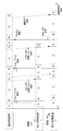
本発明の実施の形態に係る無線アクセスシステム(本システム)について図1〜図3を用いて説明する。図1は、本発明の実施の形態に係る無線アクセスシステムの構成ブロック図であり、図2は、本発明の実施の形態に係るフレームフォーマットを示す説明図であり、図3は、伝播遅延に対する距離の関係と遅延通知手順を示すタイムチャート図である。
【0014】
本実施の形態の無線アクセスシステム(本システム)は、図1に示すように、複数の加入者局(図1では加入者局装置1のみ)と、基地局装置3と、基地局装置3に接続する記憶装置4と、専用線を用いたATM網等の基幹ネットワーク6と、基幹ネットワーク6と基地局装置3とを接続するルータ(R)5と、基幹ネットワーク6に接続する管理センタ(ネットワーク管理サイト)7とから構成されている。
また、管理センタ7は、SNMPマネージャを搭載した監視用端末7aとルータ7bとから構成されている。
また、加入者局1は、加入者局装置1aとPC等の端末1bとから構成されている。以下、加入者局1を加入者局装置1と記述することがある。
【0015】
そして、基地局装置3に接続する記憶装置4には、SNMP(Simple Network Management Protocol )のMIB(Management Information Base )が蓄積されており、そのMIBの中には、基地局装置3が配下の加入者局装置1と通信を行うための加入者の情報が加入者管理情報テーブルとして記憶されている。
【0016】
次に、本発明の実施の形態に係る無線アクセスシステムの処理動作について説明する。
まず、通信事業者と新規に加入者契約が発生した場合は、図1のネットワーク管理サイト7のSNMPマネージャから、当該加入者に関する情報、例えば、加入者ID、加入者局機器アドレス(MACアドレス)、サービス条件などをSNMPにより基地局装置3へ通知し、基地局装置3は接続する記憶装置4のSNMP MIBの加入者管理情報テーブルに記憶する。
【0017】
加入者局装置1では、指向性アンテナの方位調整を行った後、送受信タイミング(送受ディレイ)を初期値として加入者局装置1に設定する。この初期値としての送受ディレイは、机上計算した伝播遅延の値である。
【0018】
そして、図2に示すフレームフォーマットが基地局装置1から繰り返し送信されている。
フレームフォーマットは、図2に示すように、A信号、B信号、C信号、D信号で構成されている。
A信号は、基地局装置3から加入者局装置1に送信される同期確立用信号である。B信号は、加入者局装置1から基地局装置3に送信される送信信号である。C信号は、運用時使用信号である。D信号は、基地局装置3から加入者局装置1に送信される送信タイミング調整値通知用信号である。
また、B信号は、フレーム特定位置判定部と、ビットずれ判定用特定ビット列で構成されている。
【0019】
基地局装置3は、図2のフレームフォーマットで加入者局装置1にA信号の同期確立用信号を送信すると、加入者局装置1はB信号の送信信号を基地局装置3に送信する。
【0020】
B信号を受信した基地局装置3は、その送信信号内のフレーム特定位置判定部を検出し、更にそれに続くビットずれ判定用特定ビット列を用いてビットずれを検知する。
【0021】
そして、基地局装置3は、検知したずれを補正するような通知をD信号の送信タイミング調整値通知信号で加入者局装置1に行う。
そのD信号の送信タイミング調整値通知信号を受信した加入者局装置1は、その信号に含まれる設定値を設定し、その設定値に従って送信のタイミングを調整する。
このようにして、加入者局装置1における送受ディレイの設定を行う。
【0022】
更に、具体的に、図3を用いて説明する。
まず、基地局装置3と加入者局装置1との距離を1kmとし、基地局装置3と加入者局装置2との距離を2kmとする。一般に、基地局装置から遠くなればなる程、遅延が生じる。
【0023】
基地局装置3は、A信号(同期確立用信号)を加入者局装置1宛に送信すると、加入者局装置1はそのA信号に応答するB信号(送信信号)を基地局装置3に送信する。B信号を受信した基地局装置3は、ビットずれを検知する。図3では100bitずれを検知したとしている。
【0024】
そして、基地局装置3は、100bitのずれを補正するように、加入者局装置1に対して100bit早く送信するようD信号(送信タイミング調整値通知用信号)を用いて通知する。
【0025】
すると、加入者局装置1は、D信号中の送信タイミング調整値を送受ディレイとして加入者局装置1内に設定する。以降は、この値を用いて加入者局装置1は送信を行うことになり、基地局装置3とずれなく同期して送受ができることになる。
【0026】
次に、基地局装置3は、次のフレームを用いてA信号(同期確立用信号)を加入者局装置2宛に送信すると、加入者局装置2はそのA信号に応答するB信号(送信信号)を基地局装置3に送信する。B信号を受信した基地局装置3は、ビットずれを検知する。図3では200bitずれを検知したとしている。
【0027】
そして、基地局装置3は、200bitのずれを補正するように、加入者局装置2に対して200bit早く送信するようD信号(送信タイミング調整値通知用信号)を用いて通知する。
【0028】
すると、加入者局装置2は、D信号中の送信タイミング調整値を送受ディレイとして加入者局装置2内に設定する。以降は、この値を用いて加入者局装置2は送信を行うことになり、基地局装置3とずれなく同期して送受信できることになる。
このようにして、加入者局装置1,2における送信タイミングを調整している。
【0029】
本発明の実施の形態の無線アクセスシステムによれば、基地局装置3から送信された同期確立信号に対して加入者局装置1が応答した送信信号内のビットずれを検知し、そのビットずれを補正するように送信タイミング調整値通知用信号を用いて加入者局装置1に送信タイミング調整値を通知し、その通知された値に従って加入者局装置1が送信を調整するようにしているので、加入者局装置1に送受信タイミング(送受ディレイ)を容易に設定することができる効果がある。
【0030】
【発明の効果】
本発明によれば、第1の無線装置と第2の無線装置との間で送受されるフレームフォーマットは、特定信号と、特定信号に続く応答信号と、応答信号に続き運用時に使用される運用時使用信号と、運用時使用信号に続く送信タイミング調整値通知用信号とから成り、第1の無線装置が、第2の無線装置に対して新規加入の設定を行う際に、特定信号を第2の無線装置に送信し、第2の無線装置から送信された応答信号を受信し、当該応答信号に基づいてタイミングずれを測定して運用時使用信号の後に第2の無線装置に当該タイミングずれを補正するタイミング調整値を含む送信タイミング調整値通知用信号を送信し、第2の無線装置が、第1の無線装置から送信された送信タイミング調整値通知用信号に含まれるタイミング調整値に基づいて送受信のタイミングを設定し、当該送受信のタイミングに基づいて応答信号を送信する無線アクセスシステムとしているので、伝播遅延に対する送信タイミングを加入者局装置に容易に設定できる効果がある。
【0031】
また、本発明によれば、タイミング調整値の通知を受けた加入者局装置は、当該値を送信タイミング値として設定し、当該送信タイミング値に従って送信を行う無線アクセスシステムとしているので、加入者局装置から基地局装置へずれなく送信できる効果がある。
【図面の簡単な説明】
【図1】本発明の実施の形態に係る無線アクセスシステムの構成ブロック図である。
【図2】本発明の実施の形態に係るフレームフォーマットを示す説明図である。
【図3】伝播遅延に対する距離の関係と遅延通知手順を示すタイムチャート図である。
【図4】基地局装置で送信される無線フレームと加入者局装置で受信される無線フレームを示す説明図である。
【符号の説明】
1…加入者局装置、 3…基地局装置、 4…記憶装置、 5…ルータ、 6…基幹ネットワーク、 7…管理センタ[0001]
BACKGROUND OF THE INVENTION
The present invention relates to a subscriber radio access system that provides a high-speed line to a user using radio, and more particularly, radio that easily sets transmission / reception timing with respect to propagation delay due to distance from a base station apparatus in the subscriber station apparatus. Relates to the access system.
[0002]
[Prior art]
With the goal of developing the next-generation information and communications infrastructure, nationwide development of subscriber-based optical fiber networks is underway with the goal of 2010, and objectives such as complementary use of subscriber-based optical fiber networks and early promotion of regional network development Therefore, there is a growing demand for subscriber wireless access systems (FWS: Fixed Wireless Access / simply called “wireless access systems”) that provide high-speed lines to subscribers using radio.
[0003]
The wireless access system includes a P-P (Point-Point) system based on inter-building communication for enterprises, and a P-MP (Point-Point) for general homes and small offices (SOHO: Small Office Home Office). MultiPoint) method is considered.
The P-MP wireless access system is composed of a single wireless base station and a plurality of subscriber stations connected by wireless lines.
[0004]
In a radio access system composed of a base station device connected to an exchange network via Ethernet and a subscriber station device connected by a wireless line, when a new subscriber station device is newly installed, the base station It is necessary to set the transmission / reception timing (delay) for the propagation delay depending on the distance from the apparatus in the subscriber station apparatus.
[0005]
This will be specifically described with reference to FIG. FIG. 4 is an explanatory diagram showing a radio frame transmitted by the base station apparatus and a radio frame received by the subscriber station apparatus.
As shown in FIG. 4, the base station apparatus transmits a radio frame including a synchronization signal and a data signal to the subscriber station apparatus. In the subscriber station apparatus, since there is a distance from the base station apparatus, it is received with a propagation delay. However, the synchronization signal includes a delay value for the subscriber ID, and the subscriber station apparatus adjusts the transmission / reception timing based on the delay value for its own subscriber ID.
[0006]
As a prior art for setting an adjustment value of a transmission timing to a base station in advance when installing a subscriber station, Japanese Patent Application Laid-Open No. 11-164353, published on June 18, 1999 (“Radio”). "Transmission timing adjustment method in communication system" (applicant: NEC Corporation, inventor: Osamu Kuboba).
In this technology, when there is no response from the base station that attempted communication, it is determined that the transmission timing setting value needs to be changed, and an operation to change the setting value stored in the transmission timing setting memory is performed from the base station. It is repeated until is obtained.
[0007]
[Problems to be solved by the invention]
However, in the conventional wireless access system, even if the setting value calculated on the desk is applied to the subscriber station apparatus, it is rarely possible to establish synchronization with the base station apparatus, and actually the communication state in the field is monitored. However, there is a problem that it is difficult to set the transmission / reception timing in the subscriber station apparatus.
Further, in the method of repeatedly changing the transmission timing value until a response from the base station is obtained as in the above prior art, there is a problem that it takes time to set the optimum transmission timing.
[0008]
The present invention has been made in view of the above circumstances, and an object of the present invention is to provide a radio access system in which transmission / reception timing with respect to propagation delay due to distance from a base station apparatus can be easily set in a subscriber station apparatus.
[0009]
[Means for Solving the Problems]
According to the present invention for solving the problems of the conventional example described above, in the wireless access system, the frame format transmitted and received between the first wireless device and the second wireless device follows the specific signal and the specific signal. A response signal, an operation use signal used in operation following the response signal, and a transmission timing adjustment value notification signal following the operation use signal, and the first wireless device transmits to the second wireless device When a new subscription is set, the specific signal is transmitted to the second wireless device, the response signal transmitted from the second wireless device is received, and the timing deviation is measured based on the response signal. transmit the transmission timing adjustment value notification signal including the timing adjustment value you correct the timing shift to the second wireless device after the time of use signal, the second wireless device, transmitted from the first wireless device Send data Set the timing of transmission and reception based on the timing adjustment value included in timing adjustment value notification signal based on the timing of the transmission and reception is characterized by transmitting a response signal, the subscriber station transmission timing for the propagation delay Easy to set.
[0010]
Further, according to the present invention, in the wireless access system, the subscriber station apparatus that has received the notification of the timing adjustment value sets the value as a transmission timing value, and performs transmission according to the transmission timing value. Transmission from the station device to the base station device can be performed without deviation.
[0011]
DETAILED DESCRIPTION OF THE INVENTION
Embodiments of the present invention will be described with reference to the drawings.
In the radio access system according to the embodiment of the present invention, when a base station device transmits a specific signal such as a synchronization signal to a newly subscribed subscriber station device, the subscriber station device can measure a timing deviation as a response signal. The base station apparatus that responds with the correct signal and receives the response signal measures the timing deviation and notifies the subscriber station apparatus of the timing adjustment value so as to correct the timing deviation. The transmission timing can be easily set in the subscriber station apparatus.
[0012]
Furthermore, in the radio access system according to the embodiment of the present invention, the subscriber station apparatus that has received the notification of the timing adjustment value sets the value as a transmission timing value and performs transmission. To the base station apparatus without deviation.
[0013]
A radio access system (this system) according to an embodiment of the present invention will be described with reference to FIGS. FIG. 1 is a configuration block diagram of a radio access system according to an embodiment of the present invention, FIG. 2 is an explanatory diagram showing a frame format according to the embodiment of the present invention, and FIG. It is a time chart which shows the relationship between distance and a delay notification procedure.
[0014]
As shown in FIG. 1, the radio access system (this system) of the present embodiment includes a plurality of subscriber stations (only the
The
The
[0015]
The storage device 4 connected to the
[0016]
Next, the processing operation of the radio access system according to the embodiment of the present invention will be described.
First, when a new subscriber contract is generated with a communication carrier, information on the subscriber, for example, a subscriber ID, a subscriber station device address (MAC address) is received from the SNMP manager of the
[0017]
In the
[0018]
The frame format shown in FIG. 2 is repeatedly transmitted from the
As shown in FIG. 2, the frame format is composed of A signal, B signal, C signal, and D signal.
The A signal is a synchronization establishment signal transmitted from the
The B signal includes a frame specific position determination unit and a bit shift determination specific bit string.
[0019]
When the
[0020]
The
[0021]
The
The
In this way, the transmission / reception delay in the
[0022]
Furthermore, it demonstrates concretely using FIG.
First, the distance between the
[0023]
When the
[0024]
Then, the
[0025]
Then, the
[0026]
Next, when the
[0027]
Then, the
[0028]
Then, the subscriber station apparatus 2 sets the transmission timing adjustment value in the D signal in the subscriber station apparatus 2 as a transmission / reception delay. Thereafter, the subscriber station apparatus 2 performs transmission using this value, and can transmit and receive in synchronization with the
In this way, the transmission timing in the
[0029]
According to the radio access system of the embodiment of the present invention, a bit shift in the transmission signal that the
[0030]
【The invention's effect】
According to the present invention, the frame format transmitted / received between the first radio apparatus and the second radio apparatus includes a specific signal, a response signal following the specific signal, and an operation used during operation following the response signal. And a transmission timing adjustment value notification signal following the operation use signal. When the first wireless device sets a new subscription to the second wireless device, the specific signal is 2 is transmitted to the second wireless device, the response signal transmitted from the second wireless device is received, the timing shift is measured based on the response signal, and the second wireless device receives the timing shift after the operation use signal. transmit the transmission timing adjustment value notification signal including the timing adjustment value for correcting the second wireless device, based on the timing adjustment value included in the transmission timing adjustment value notification signal transmitted from the first wireless device To set the timing of transmission and reception, since the wireless access system for transmitting a response signal based on the timing of the transmission and reception, there is an effect that can be easily set to the subscriber station apparatus the transmission timing for the propagation delay.
[0031]
Further, according to the present invention, the subscriber station apparatus that has received the notification of the timing adjustment value sets the value as a transmission timing value, and is a radio access system that performs transmission according to the transmission timing value. There is an effect that transmission can be performed without deviation from the apparatus to the base station apparatus.
[Brief description of the drawings]
FIG. 1 is a configuration block diagram of a radio access system according to an embodiment of the present invention.
FIG. 2 is an explanatory diagram showing a frame format according to the embodiment of the present invention.
FIG. 3 is a time chart showing the relationship of distance to propagation delay and the delay notification procedure.
FIG. 4 is an explanatory diagram showing a radio frame transmitted by a base station apparatus and a radio frame received by a subscriber station apparatus.
[Explanation of symbols]
DESCRIPTION OF
Claims (3)
前記第1の無線装置と前記第2の無線装置との間で送受されるフレームフォーマットは、特定信号と、前記特定信号に続く応答信号と、前記応答信号に続き運用時に使用される運用時使用信号と、前記運用時使用信号に続く送信タイミング調整値通知用信号とから成り、
前記第1の無線装置が、前記第2の無線装置に対して新規加入の設定を行う際に、特定信号を前記第2の無線装置に送信し、前記第2の無線装置から送信された応答信号を受信し、当該応答信号に基づいてタイミングずれを測定して前記運用時使用信号の後に前記第2の無線装置に当該タイミングずれを補正するタイミング調整値を含む送信タイミング調整値通知用信号を送信し、
前記第2の無線装置が、前記第1の無線装置から送信された送信タイミング調整値通知用信号に含まれるタイミング調整値に基づいて送受信のタイミングを設定し、前記送受信のタイミングに基づいて前記応答信号を送信することを特徴とする無線アクセスシステム。In a wireless access system comprising a first device connected to a backbone network and a second wireless device connected to the first wireless device via a wireless line,
The frame format transmitted / received between the first radio apparatus and the second radio apparatus includes a specific signal, a response signal following the specific signal, and an operation use used during operation following the response signal. A signal and a transmission timing adjustment value notification signal following the operation use signal,
When the first wireless device sets a new subscription for the second wireless device, the specific signal is transmitted to the second wireless device, and the response transmitted from the second wireless device receiving a signal, transmission timing adjustment value notification signal including the timing adjustment value you correct the timing shift to the second wireless device after the operation when using signals by measuring the timing deviation based on the response signal Send
The second wireless device sets a transmission / reception timing based on a timing adjustment value included in a transmission timing adjustment value notification signal transmitted from the first wireless device, and the response based on the transmission / reception timing A radio access system characterized by transmitting a signal.
Priority Applications (1)
| Application Number | Priority Date | Filing Date | Title |
|---|---|---|---|
| JP35182899A JP4390938B2 (en) | 1999-12-10 | 1999-12-10 | Wireless access system |
Applications Claiming Priority (1)
| Application Number | Priority Date | Filing Date | Title |
|---|---|---|---|
| JP35182899A JP4390938B2 (en) | 1999-12-10 | 1999-12-10 | Wireless access system |
Publications (3)
| Publication Number | Publication Date |
|---|---|
| JP2001169345A JP2001169345A (en) | 2001-06-22 |
| JP2001169345A5 JP2001169345A5 (en) | 2007-01-25 |
| JP4390938B2 true JP4390938B2 (en) | 2009-12-24 |
Family
ID=18419896
Family Applications (1)
| Application Number | Title | Priority Date | Filing Date |
|---|---|---|---|
| JP35182899A Expired - Fee Related JP4390938B2 (en) | 1999-12-10 | 1999-12-10 | Wireless access system |
Country Status (1)
| Country | Link |
|---|---|
| JP (1) | JP4390938B2 (en) |
Families Citing this family (9)
| Publication number | Priority date | Publication date | Assignee | Title |
|---|---|---|---|---|
| US6873662B2 (en) | 2002-02-14 | 2005-03-29 | Interdigital Technology Corporation | Wireless communication system having adaptive threshold for timing deviation measurement and method |
| US7574224B2 (en) * | 2005-06-13 | 2009-08-11 | Qualcomm Incorporated | Methods and apparatus for performing timing synchronization with base stations |
| US8036205B2 (en) * | 2005-06-13 | 2011-10-11 | Qualcomm Incorporated | Methods and apparatus for supporting uplinks with remote base stations |
| US7974261B2 (en) * | 2005-06-13 | 2011-07-05 | Qualcomm Incorporated | Basestation methods and apparatus for supporting timing synchronization |
| JP2007201851A (en) * | 2006-01-27 | 2007-08-09 | Hitachi Kokusai Electric Inc | Wireless communication apparatus |
| US8644396B2 (en) | 2006-04-18 | 2014-02-04 | Qualcomm Incorporated | Waveform encoding for wireless applications |
| WO2007127878A1 (en) | 2006-04-26 | 2007-11-08 | Qualcomm Incorporated | Dynamic distribution of device functionality and resource management |
| US8406794B2 (en) | 2006-04-26 | 2013-03-26 | Qualcomm Incorporated | Methods and apparatuses of initiating communication in wireless networks |
| US8289159B2 (en) | 2006-04-26 | 2012-10-16 | Qualcomm Incorporated | Wireless localization apparatus and method |
-
1999
- 1999-12-10 JP JP35182899A patent/JP4390938B2/en not_active Expired - Fee Related
Also Published As
| Publication number | Publication date |
|---|---|
| JP2001169345A (en) | 2001-06-22 |
Similar Documents
| Publication | Publication Date | Title |
|---|---|---|
| US8520677B2 (en) | Method of data rate adaptation for multicast communication | |
| US6282430B1 (en) | Method for obtaining control information during a communication session in a radio communication system | |
| JP5827194B2 (en) | Network device and transmission power control method | |
| JP3113671B2 (en) | Communications system | |
| EP1214815B1 (en) | Dual mode subscriber unit for short range, high rate and long range, lower rate data communications | |
| CN101663861B (en) | Frequency scanning to form a communication network | |
| US5553074A (en) | Transmission format in packet based communications | |
| WO2001015387A1 (en) | Direct mode communication method between two mobile terminals in access point controlled wireless lan systems | |
| US8086232B2 (en) | Time synchronized wireless method and operations | |
| JP3621113B2 (en) | Method and apparatus in a wireless communication system for implementing a frequency reuse scheme | |
| CN101689935A (en) | Delay control in a mobile communication system | |
| TWI491231B (en) | Proxy mechanism for mesh-type networks | |
| CN101971571A (en) | Modem timing offset compensation for line card redundancy failover | |
| JP4390938B2 (en) | Wireless access system | |
| KR20020020848A (en) | Reconfiguration of an ad hoc network | |
| WO2022182184A1 (en) | Method and apparatus for exchanging traffic characteristics information in wi-fi systems | |
| WO2014139307A1 (en) | Method and apparatus for mcs switching | |
| JP2000069033A (en) | Radio communication system | |
| KR20020067638A (en) | Network comprising a plurality of sub-networks which can be linked via bridge terminals | |
| CN1513272B (en) | Method for establishing communicaiton channels between network elements | |
| CN117580141B (en) | Power negotiation method, device, system, medium, routing equipment and terminal | |
| JP4057445B2 (en) | Wireless access system | |
| JP2001156824A (en) | Subscriber system network device and repeater station | |
| Cheng et al. | Multi-rate Transmissions in Infrastructure Wireless LAN based on IEEE 802.11 b Protocol | |
| JP2003009208A (en) | Portable telephone system and synchronous relay system used for the same |
Legal Events
| Date | Code | Title | Description |
|---|---|---|---|
| A521 | Written amendment |
Free format text: JAPANESE INTERMEDIATE CODE: A523 Effective date: 20061201 |
|
| A621 | Written request for application examination |
Free format text: JAPANESE INTERMEDIATE CODE: A621 Effective date: 20061201 |
|
| A977 | Report on retrieval |
Free format text: JAPANESE INTERMEDIATE CODE: A971007 Effective date: 20090126 |
|
| A131 | Notification of reasons for refusal |
Free format text: JAPANESE INTERMEDIATE CODE: A131 Effective date: 20090203 |
|
| A521 | Written amendment |
Free format text: JAPANESE INTERMEDIATE CODE: A523 Effective date: 20090406 |
|
| A131 | Notification of reasons for refusal |
Free format text: JAPANESE INTERMEDIATE CODE: A131 Effective date: 20090709 |
|
| A521 | Written amendment |
Free format text: JAPANESE INTERMEDIATE CODE: A523 Effective date: 20090902 |
|
| TRDD | Decision of grant or rejection written | ||
| A01 | Written decision to grant a patent or to grant a registration (utility model) |
Free format text: JAPANESE INTERMEDIATE CODE: A01 Effective date: 20090930 |
|
| A01 | Written decision to grant a patent or to grant a registration (utility model) |
Free format text: JAPANESE INTERMEDIATE CODE: A01 |
|
| A61 | First payment of annual fees (during grant procedure) |
Free format text: JAPANESE INTERMEDIATE CODE: A61 Effective date: 20091007 |
|
| FPAY | Renewal fee payment (event date is renewal date of database) |
Free format text: PAYMENT UNTIL: 20121016 Year of fee payment: 3 |
|
| R150 | Certificate of patent or registration of utility model |
Free format text: JAPANESE INTERMEDIATE CODE: R150 |
|
| FPAY | Renewal fee payment (event date is renewal date of database) |
Free format text: PAYMENT UNTIL: 20121016 Year of fee payment: 3 |
|
| FPAY | Renewal fee payment (event date is renewal date of database) |
Free format text: PAYMENT UNTIL: 20131016 Year of fee payment: 4 |
|
| LAPS | Cancellation because of no payment of annual fees |