JP4388624B2 - Endless orbit - Google Patents
Endless orbit Download PDFInfo
- Publication number
- JP4388624B2 JP4388624B2 JP14657399A JP14657399A JP4388624B2 JP 4388624 B2 JP4388624 B2 JP 4388624B2 JP 14657399 A JP14657399 A JP 14657399A JP 14657399 A JP14657399 A JP 14657399A JP 4388624 B2 JP4388624 B2 JP 4388624B2
- Authority
- JP
- Japan
- Prior art keywords
- tread
- wheel
- width
- endless track
- angle
- Prior art date
- Legal status (The legal status is an assumption and is not a legal conclusion. Google has not performed a legal analysis and makes no representation as to the accuracy of the status listed.)
- Expired - Lifetime
Links
Images


Classifications
-
- B—PERFORMING OPERATIONS; TRANSPORTING
- B62—LAND VEHICLES FOR TRAVELLING OTHERWISE THAN ON RAILS
- B62D—MOTOR VEHICLES; TRAILERS
- B62D55/00—Endless track vehicles
-
- B—PERFORMING OPERATIONS; TRANSPORTING
- B62—LAND VEHICLES FOR TRAVELLING OTHERWISE THAN ON RAILS
- B62D—MOTOR VEHICLES; TRAILERS
- B62D55/00—Endless track vehicles
- B62D55/08—Endless track units; Parts thereof
- B62D55/18—Tracks
- B62D55/24—Tracks of continuously flexible type, e.g. rubber belts
-
- B—PERFORMING OPERATIONS; TRANSPORTING
- B60—VEHICLES IN GENERAL
- B60C—VEHICLE TYRES; TYRE INFLATION; TYRE CHANGING; CONNECTING VALVES TO INFLATABLE ELASTIC BODIES IN GENERAL; DEVICES OR ARRANGEMENTS RELATED TO TYRES
- B60C11/00—Tyre tread bands; Tread patterns; Anti-skid inserts
- B60C11/03—Tread patterns
- B60C11/0311—Patterns comprising tread lugs arranged parallel or oblique to the axis of rotation
- B60C2011/0313—Patterns comprising tread lugs arranged parallel or oblique to the axis of rotation directional type
Description
【0001】
【発明の背景】
【0002】
【発明の分野】
本発明は、全般的には高速道路以外で用いられる車両(off-highway vehicles)の無限軌道(endless tracks)に関し、特に、トレッド・車輪振動(tread-wheel vibration)を最小限に抑える無限軌道の形状(track configuration)に関する。具体的には、本発明は無限軌道が装着されている車輪において、車輪の振動を最小限に抑えるトレッド角と車輪幅との関係に関する。
【0003】
【発明の背景】
無限軌道はカレンダー加工したスチールベルトなどで強化したエラストマー材料で製作されることが多い。無限軌道の外側表面は、凹凸の激しい(rough)、とぎれとぎれの(broken)、あるいは軟弱な土地をしっかり捉らえ、この無限軌道を用いている車両に牽引力を与えるように設計された、複数の間隔を置いた突起(lug)を具備するのが普通である。無限軌道の内側表面は、支持駆動車輪アセンブリー(supporting drive wheel assembly)を中心にして無限軌道を駆動する駆動車輪が係合する中央に設けた突起部分によって互いに間隔をおく一対の比較的滑らかなランナーをもつ。支持駆動車輪アセンブリーには突起部分の両側に位置する滑らかなランナーの上を走る(ride)ボギー車輪とアイドラーがあってもよい。これらの車輪は支持駆動車輪の周囲で無限軌道の整合性を維持する助けになる。
【0004】
無限軌道車両(tracked vehicles)は、凹凸の激しい表面上での運転を目的として設計されるのが最も一般的であり、車両に相当な振動が生じたり全般に乗り心地が悪い。表面に由来する振動(surface-related vibrations)が凹凸のある表面で生じるのは予期されることであるが、トレッド・車輪振動(tread wheel vibration)は凹凸のある表面でも、比較的滑らかな表面でも生じる。トレッド・車輪振動は、無限軌道で走行する車両が、交互に剛性(alternating stiffness)を経験するために発生する。交互に生じる剛性は、無限軌道の外部に間隔をおいて設けた突起に起因する。上記のように、突起は無限軌道の外側表面に位置しているが、車輪は比較的滑らかな表面と係合している。車輪が突起の真上にあるときは、無限軌道の剛性は比較的しっかりしているが、車輪が突起と突起の隙間のうえにあるときはいくらか剛性が落ちる。こうした剛性が車輪に、従って車両に振動をもたらす。
【0005】
従って、トレッド・車輪振動は突起同士の間隔を小さくして、車輪に剛性の変化が感じられないようにすれば基本的にはゼロになると考えられる。しかし、そのような設計では十分な牽引力が得られない。
【0006】
トレッド・車輪振動は、車輪の軸受け、車軸などの寿命に悪影響を及ぼし、無限軌道車両のメンテナンスの必要回数が増える。トレッド・車輪振動は車両の乗り心地を減じる。従って、振動を最小限に抑え、車両に牽引力ももたらすトレッドパターンを提供することが望まれる。
【0007】
【発明の要旨】
上記の観点から、本発明の目的は突起パターンと車輪幅のアレンジメントが相俟って無限軌道のトレッド・車輪振動を最小限に抑える車両用の無限軌道を提供することにある。
【0008】
本発明の他の目的は、車輪幅と突起のトレッド角を相関させて無限軌道のトレッド・車輪振動を減少させる無限軌道を提供することにある。
【0009】
本発明のさらなる目的は、トレッド・車輪振動を最小限にする無限軌道用のトレッドパターンの設計方法を提供することにある。
【0010】
本発明の他の目的は、無限軌道が設けられる車両に、より高い牽引力をもたらすトレッドパターンをもつ無限軌道を提供することにある。
【0011】
これらならびその他の本発明の目的と利点は、エラストマーの改良された無限軌道によって得られるもので、その概要はエラストマー製の無限軌道(endless elastomeric drive track)と、各車輪の幅が(B)である複数の車輪の組み合わせを含むものということができるが、無限軌道はエンドレスベルトと、複数の突起をもつトレッドをもち、エンドレスベルトは長手方向の軸をもち、各突起はベルトに対してトレッド角(a)とトレッドピッチ(P)をもち、トレッドピッチ、トレッド角、車輪幅はトレッド・車輪無振動式P=B*tan(a)の関係をもつ。
【0012】
本発明のその他の目的は、最小限のトレッド・車輪振動をもつ車両用無限軌道の設計方法によって達成されるもので、車両は無限軌道の内部(interior)と係合する車輪を少なくとも一つもち、無限軌道は、無限軌道のトレッドピッチとトレッド角をもち、前記方法はトレッドピッチ、トレッド角、車輪幅のうちいずれか2項目を決定し、残るトレッドピッチ、トレッド角、または車輪幅を式から決定することを含む。
【0013】
本発明のさらに他の目的は、複数の車輪の周囲に配置されるエラストマー製無限軌道によって達成されるもので、無限軌道は長手方向の軸をもつ本体部分、内側表面、そしてほぼ平面の外側表面をもち、長手方向に間隔をおいた複数の外部突起は本体の外側表面から外方向に突出し、各突起は第1と第2の部分をもち、第1と第2の部分は長手方向の軸を挟んで互いに間隔をおいて位置し、かつ、長手方向軸を中心にして互いにほぼ鏡像をなし、各部分は第1と第2の脚部をもち、第1の脚部は長手方向軸にほぼ垂直に位置し、第2の脚部は第1の脚部からトレッド角をなして背後方向に延在する。
【0014】
【好ましい実施例の説明】
本出願人が原理の応用を意図する本発明の好ましい実施例の最善の態様を、以下に説明し、図面で示し、クレームに具体的かつ明確に指摘し記述する。図中、同様の数字は同様の部分を示す。
【0015】
本発明に従って製作される無限軌道の全体を添付図面では数字10で示す。踏面10は、高速道路以外で使用される代表的な車両を駆動するのに用いられる複数の駆動車輪の周囲に配置された状態を略図として図8に示す。駆動車輪はパワー駆動車輪(powered drive wheel)12、複数のアイドラー車輪14、複数のボギー車輪16を含むことができる。図11からわかるように、無限軌道10は、金属ワイヤあるいはケーブル22など、カレンダープライ(calendered plies)である複数の強化プライを担持(carries)する本体20を含む。無限軌道10はまた、無限軌道10が駆動車輪12と係合することで、駆動車輪が無限軌道を車輪12、14、16の周囲で駆動できるような形状をもつ一連の内部突起24をもつ。内部突起24は中心に向かって配置され長手方向に整列している。ほぼ平面で長手方向に無限の部分が内面突起の両側に配置され、数字26で示されている。トレッド28が無限軌道10の外側に配置され、複数の外部突起32を含む。
【0016】
外部突起32には、無限軌道10が用いられる車両に牽引力を与える各種パターンを施す。本技術分野で知られるパターンのひとつを図2に示す。このパターンでは、外部突起32は、無限軌道10の中央長手方向軸34の両側に沿って部分的に変化する(altering)、すなわち互い違いにずらした(staggered)配置になっている。図3、図9に、完全な山形パターン(full chevron pattern)を示す。完全な山形パターンの場合は、外部突起32は連続していて、中央の長手方向軸にそって互いにほぼ鏡像をなす。
【0017】
本発明のもうひとつの実施例を図12に示すが、外部突起32は改良スプリット型山形パターン(improved split chevron pattern)として配置されている。このパターンでは、本体20はほぼ平面の外側表面31を含み、ここから外側突起32が外方向に突出している。スプリット型山形パターンの外部突起32は、突起32の脚部がそれぞれ他の突起32の対応する脚部と平行になるように間隔をおいて設けられている。改良スプリット型山形パターンの各突起32は、全体を数字33で示す第1の部分と、全体を数字35で示す第2の部分を含む。
【0018】
第1の部分33と第2の部分35は、長手方向の軸34をはさんでギャップ36によって間隔を隔てられており、第1の部分33が第2の部分35と接触する部分は全くない。第1の部分33は長手方向軸34にそって実質的に第2の部分35の鏡像をなす。部分33と35はそれぞれ、第1の脚部37と、第1の脚部37の外端部から角度をなして伸びる第2の脚部38をふくむ。第1の脚部37は長手方向軸34に対してほぼ垂直であり、一方第2の脚部38は以下に詳しく述べるように第1の脚部37からトレッド角をなして延在する。
【0019】
改良スプリット型山形の外部突起32のパターンは、図2に示すトレッド形状に比べ、さまざまな土壌条件においてより優れた牽引力をもたらす。図12の改良スプリット型山形形状は、図3、図9に示す山形形状の改良牽引力をさらに増強(build upon)するが、外部突起32の面積はさらに小さくなるため、無限軌道10の浮揚能力(floatation capabilities)を減少させる。これにより、無限軌道10はより深く土壌中に食い込むことができ、牽引力が増大する。
【0020】
図1からわかるように、ボギー車輪16が対で作動するように車軸40によって連結されている。ボギー車輪16と車軸40は、無限軌道10が車輪16の下を通過する際に車軸40が内側突起24と接触しないような形状になっている。ボギー車輪が平面部分26の無限軌道の車輪接触部分(endless wheel contact areas)42に対して回転する際に、トレッド・車輪振動が生じる。ボギー車輪16が外部突起32と直接接触する部分から突起と突起の間の部分へと通過する際に、ボギー車輪16に伝わる剛性が変化することで好ましくないトレッド・車輪振動が生じる。ボギー車輪16が外部突起32の真上に位置するときを、ボギー車輪は外部突起32と接触していると言う。ボギー車輪16が外部突起32と接触しているとき、ボギー車輪16に伝わる無限軌道10の剛性は、ボギー車輪16が外部突起32間にある部分44と接触している時の剛性より高い。したがって、無限軌道10が連続的にボギー車輪16の下を通過すると、ボギー車輪16に伝わる剛性は常に変化し、トレッド・車輪振動が生じることがわかる。
【0021】
本発明の主たる目的の一つによれば、トレッド28はトレッド・車輪振動を大幅に減少させるような形状になっている。トレッド28は、文字aで示すトレッド角、Pで示すトレッドピッチ、Bで示すボギー車輪の幅を相関させることでトレッド・車輪振動を最小限に抑えるような形状をもつ(図4参照)。
【0022】
図4は、無限軌道10が設けられる車両が走行中に、単一のボギー車輪16が接触する無限軌道の車輪接触部分42の一つの断面を示す。陰影部分(stippled)は、無限軌道10の反対側(opposite side)の外部突起32の位置を示す。このような状態では、ボギー車輪16に伝わる剛性は、ボギー車輪16が陰影部分に接触すると高くなる。各突起32は無限軌道10の長手方向軸に対して角度bをなして配置されている。トレッド角は従って90度から角度bを差し引いて求める。各外部突起32は外部突起32間の距離を表すピッチPをもつ。接触部分42の幅は、ボギー車輪16の幅にほぼ等しい。各外部突起32の幅はHで示す。
【0023】
さらに図4を参照すると、ボギー車輪16は外部突起32の位置を表す陰影部分と正接方向に接触している(tangential contact)と見なせることが理解される。正接接触をLで示す車輪接触長さとする。図4に示す本発明の実施例においては、車輪接触長さLは、L2にL1を加えた合計として示すように、2つの隣接突起32の接触長さの和である。トレッド・車輪振動の測定の一つのやり方として、車輪16が車輪接触部分42に対して動くときの車輪接触長さの変化を測定する。車輪の正接方向の位置を表す寸法(dimension)Xが変化すると、車輪接触長さLが変化する。本発明の別の目的によれば、車輪16が外部突起32のピッチP全域を移動する際、車輪接触長さLがまったく変動しないか、ほとんど変動しない、トレッド28形状が提供される。車輪接触長さLが突起32のピッチP全域で一定に保たれるとき、剛性の変動は有意に減少する。
【0024】
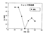
トレッド角を変化させながら車輪幅Bを一定に保つことの効果を、グラフとして図5に示す。図5のX軸はトレッド角、Y軸は振動測定値を表す。振動測定値は次式から求められる(Lmax−Lmin)/(Lmax*100)。従って、トレッド角が約25°になるまでは振動がほぼ約100%であることがわかる。トレッド角がさらに増大すると、振動は有意に減少して、トレッド角が約35°になったどころで、振動はほぼゼロに達する。ついで、振動はトレッド角が約45°になるまで増大し、その後、再び減少する。従って、トレッド角を約35°、車輪幅を218mm,ピッチを約152mmに設定するのが望ましいことがわかる。
【0025】
図6に、トレッド角を35°に固定したときの振動と車輪幅の関係を示す。車輪幅が約160mmを超えたところで、振動が有意に減少しはじめ、車輪幅が約218mmでゼロになることがわかる。ついで、振動は増大して、車輪が約300mmを超えると平坦になる。
【0026】
図7は、ピッチPを変化させたときの最適車輪幅Bとトレッド角の関係を示す。グラフに示す線はそれぞれ、トレッド10におけるトレッド・車輪振動を最小にするための最適パラメーターを表す。たとえば、図5、6に示す情報は、トレッド角が約35°の時、ピッチが約6”であれば、最適車輪幅は約218mmであることを示している。このようなグラフは、特定の車輪幅Bについて、外部トレッド32形状を設計する際に役にたつ。具体的に言えば、トレッド角を変更する場合は、新しい工具や金型(mold)が必要になるため、トレッド角を変更するよりは、車輪幅Bの設計変更をするほうが簡単である。
【0027】
上記の情報から、車輪接触長さLにおける変動を最小限に抑えて、Lmax寸法とLmin寸法を、等しくないまでもできるだけ近い値にすることが望ましいことがわかる。このような変動を最小限にするトレッド28を得るために、次のような式が導かれた:P=Btan(a)。この式により、突起32の間隔を車輪幅Bとトレッド角に相関させる。従って、この式を用いることで、特定応用例におけるトレッド・車輪振動を最小にするトレッド28を設計することが可能になる。一つの解として、車輪幅Bを固定し、ピッチPとトレッド角を変化させる。ついで、所望のピッチPまたは角度aを選び、式を使って残りの寸法を計算すればよい。その結果、決まる寸法からは、トレッド・車輪振動が最小のトレッド28と車輪16の組み合わせが得られる。こうして得られた寸法が、製造あるいは使用の面で実用性に欠ける場合は、寸法のいずれかを再調整して、もう一度設計をやり直せばよい。この式から完璧な結果が得られない場合は、図5、6、7に示した情報による変数のいずれかを修正して、振動が最小の実用的なトレッド28を求める。ついで、振動をさらに減少させるために突起幅Hを大きくしてもよい。しかし、上述のように、トレッド角を現在使用中の金型のトレッド角に固定しておくほうが一般に望ましい。したがって、振動の最も少ないトレッド28を得るには、車輪幅Bの寸法を変化させる。
【0028】
その結果、改良トレッド・車輪設計装置が簡単になり、列挙した目的のすべてを達成する効果的、安全、安価かつ効率的な装置が得られ、従来装置でみられた困難を排除し、問題を解決して本技術における新しい成果をもたらす。
【0029】
上記の説明では、簡潔さ、明確さと理解を助けるために特定の用語を用いたが、これらは従来技術から求められる以上の不必要な限定を示唆するものではなく、説明を目的として用いられ広義の解釈を意図するものである。
【0030】
さらに、本発明の説明および図は、例示を目的としたもので、これらに図示あるいは記述される詳細によって本発明の範囲は限定されない。
【0031】
本発明の特長、発見、原則、改良トレッド設計の解釈と使用、構成の特徴と利点、得られる新規で有用な結果を説明したところで、新規で有用な構造、装置、要素、アレンジメント、部品と組み合わせ、を以下に記載する。
【0032】
1. エラストマーの無限軌道と、それぞれが車輪幅Bをもつ複数の車輪の組み合わせであって、前記無限軌道はエンドレスベルトと複数の間隔を設けた突起をもつトレッドを含み、前記エンドレスベルトは長手方向の軸をもち、前記突起はそれぞれ前記ベルトに対するトレッド角(a)とトレッドピッチ(P)をもち、前記トレッドピッチ(P)、トレッド角(a)および車輪幅(B)は、トレッド−車輪無振動式P=B*tan(a)の関係をもつ、組み合わせ。
【0033】
2. 前記複数の間隔を設けた突起が完全な山形パターンの配置をもつ、上記1に記載の組み合わせ。
【0034】
3. 前記複数の間隔を設けた突起のそれぞれが、前記長手方向軸をはさんで互いに間隔を設けた第1と第2の部分をもつ、上記1に記載の組み合わせ。
【0035】
4. 前記部分がそれぞれ、第1と第2の脚部を含み、前記第1の脚部は前記長手方向軸にほぼ垂直に配置され、前記第2の脚部は前記トレッド角で配置される、上記3に記載の組み合わせ。
【0036】
5. 前記トレッドは、前記複数の車輪の一つと接触するとき最大接触長さ(Lmax)と最小接触長さ(Lmin)をもち、振動の指数(an indicia)は(Lmax−Lmin)/(Lmax*100)と定義され、前記振動の指数は前記突起ピッチ(P)、トレッド角(a)および車輪幅(B)が前記トレッド・車輪振動式によって規定されるとき最小になる、上記1に記載の組み合わせ。
【0037】
6. 車輪幅が約218mmの時、前記トレッド角(a)が約35度である、上記5に記載の組み合わせ。
【0038】
7. 複数の車輪の周囲に配置されるエラストマーの無限軌道であって、前記無限軌道が、
外側表面と内側表面をもつエンドレスベルトを具備し、
前記エンドレスベルトは長手方向軸をもち、
前記エンドレスベルトは前記長手方向軸にほぼ平行な車輪接触部分を少なくとも一つもつ、
前記車輪接触部分は前記複数の車輪のひとつの幅とほぼ等しい幅(B)をもち、
更に前記エンドレスベルトの外側表面から延在する複数の間隔をおいた突起を具備し、
前記突起はそれぞれ前記車輪接触部分に対してトレッド角(a)をなして配置され、
前記突起はそれぞれトレッドピッチ(P)をもち、
前記車輪接触部分は複数の車輪の一つと係合する際、突起に対して最大接触長さと最小接触長さをもち、
前記接触長さは前記トレッドピッチにそってほぼ一定である、
ことからなるエラストマーの無限軌道。
【0039】
8. 前記複数の間隔をおいた突起がそれぞれ、前記長手方向軸をはさんで互いに間隔をおいた第1と第2の部分を含む、上記7に記載のエラストマーの無限軌道。
【0040】
9. 前記部分はそれぞれ、第1と第2の脚部を含み、前記第1の脚部は前記長手方向軸にほぼ垂直に配置され、前記第2の脚部は前記トレッド角で配置される、上記8に記載のエラストマーの無限軌道。
【0041】
10. 前記複数の突起が完全な山形パターンに配置される、上記7に記載のエラストマーの無限軌道。
【0042】
11. 前記トレッドピッチ(P)、トレッド角(a)、車輪幅(B)が、トレッド・車輪振動式P=B*tan(a)の関係をもつ、上記7に記載のエラストマー無限軌道。
【0043】
12. 車輪幅が約218mmの時前記トレッド角が約35度である、上記11に記載のエラストマー無限軌道。
【0044】
13. トレッド・車輪振動が最小である車両の無限軌道を設計する方法であって、車両は無限軌道内部と係合する車輪を少なくとも一つもち、無限軌道はトレッドピッチ(P)とトレッド角(a)をもつ設計方法であって、
無限軌道についてトレッドピッチ(P)、トレッド角(a)あるいは車輪幅のいずれか2項目を決定し、
トレッドピッチ(P)、トレッド角(a)あるいは車輪幅のうち残る項目を式P=B*tan(a)から決定する、
ステップからなる方法。
【0045】
14. さらに、牽引力のためにトレッド幅(H)を調節するステップを含む上記13に記載の方法。
【0046】
15. さらに、振動をさらに減少させるためにトレッド幅(H)を増大させるステップを含む上記13に記載の方法。
【0047】
16 いずれか2項目を決定するステップがトレッド角を約35度に設定することを含む上記13に記載の方法。
【0048】
17. 複数の車輪の周囲に配置されるエラストマー無限軌道であって、前記無限軌道が、
長手方向軸、内部表面、ほぼ平面の外側表面をもつ本体、及び
前記本体の外側表面から外方向に突出し、長手方向に間隔をおいた複数の外部突起を具備し、
前記突起はそれぞれ、第1、第2の部分をもち、前記第1、第2の部分は前記長手方向軸をはさんで互いに間隔をおいて配置され、前記長手方向軸を中心にして互いにほぼ鏡像をなし、
前記部分はそれぞれ第1の脚部と第2の脚部をもち、
前記第1の脚部は前記長手方向軸に対してほぼ垂直に配置され、
前記第2の脚部は前記第1の脚部からトレッド角をなして背後方向に延在する、ことからなるエラストマー無限軌道。
【0049】
18. 前記トレッド角が約30度から約40度の範囲にある、上記17に記載のエラストマー無限軌道。
【0050】
19. 前記トレッド角が約35度である、上記18に記載のエラストマー無限軌道。
【0051】
20. 前記本体の内側表面は前記第2の脚部と整列させた一対の車輪接触部分をもち、前記車輪接触部分は幅(B)をもち、前記第2の脚部はそれぞれ前記車輪接触部分においてトレッドピッチ(P)をもち、前記トレッドピッチ(P)、前記トレッド角(a)、前記車輪接触部分の幅(B)は、トレッド・車輪無振動式P=B*tan(a)の関係をもつ、上記17に記載のエラストマー無限軌道。
【図面の簡単な説明】
【図1】 内部突起を取り除いた、突起付き無限軌道の平坦部分と係合する一対のボギー車輪の斜視図であり、陰影部分は外部突起の位置を表す。
【図2】 互い違いに配置したトレッドパターンを示す、本発明の無限軌道の一部の上部平面図。
【図3】 完全な山形トレッドパターンを示す、本発明の無限軌道の他の部分の上部平面図。
【図4】 ボギー車輪の一つと係合する無限軌道部分の上面図。
【図5】 車輪幅を218mmに保った場合の振動とトレッド角の関係を表すグラフ。
【図6】 トレッド角を35°に保った場合の振動と車輪幅の関係を表すグラフ。
【図7】 異なるトレッドピッチでの車輪幅とトレッド角の関係を示すグラフ。
【図8】 複数の駆動車輪、アイドラー車輪、ボギー車輪の周囲に配置した無限軌道の前部立面図。
【図9】 完全な山形トレッドパターンの底部平面図。
【図10】 図8の線10−10方向を見た部分平面図。
【図11】 図9の線11−11に沿った拡大断面図。
【図12】 改良スプリット型山形トレッドパターンの一部の底部平面図。
【符号の説明】
10 無限軌道
12 車輪
14 車輪
16 車輪
32 突起
34 長手方向軸[0001]
BACKGROUND OF THE INVENTION
[0002]
FIELD OF THE INVENTION
The present invention relates generally to endless track vehicle used outside the highway (off-highway vehicles) (endless tracks), in particular, the track suppressing tread wheel vibrate (tread-wheel vibration) to a minimum Concerning the track configuration. Specifically, the present invention relates to a relationship between a tread angle and a wheel width that minimizes wheel vibration in a wheel on which an endless track is mounted.
[0003]
BACKGROUND OF THE INVENTION
Endless tracks are often made of an elastomeric material reinforced with a calendered steel belt. The outer surface of the endless track is designed to capture rugged, broken, or soft terrain and provide traction to vehicles using this endless track . It is common to have spaced lugs. The inner surface of the endless track, a pair of relatively smooth runner spaced from each other driving wheels by a projection portion provided at the center to engage for driving the endless track around the support drive wheel assembly (supporting drive wheel assembly) It has. The support drive wheel assembly may have bogie wheels and idlers that ride on smooth runners located on either side of the protrusion. These wheels help maintain endless track integrity around the supporting drive wheels.
[0004]
Tracked vehicle (tracked vehicles) is the most commonly are designed for operation on heavy surface irregularities, poor ride considerable vibration occurs or in general to a vehicle. It is expected that surface-related vibrations will occur on uneven surfaces, but tread wheel vibration can be on uneven surfaces or relatively smooth surfaces. Arise. Tread and wheel vibrations occur because vehicles traveling on endless tracks experience alternating stiffness. Alternating stiffness results from protrusions provided at intervals outside the endless track . As described above, the protrusion is located on the outer surface of the endless track, but the wheel is engaged with a relatively smooth surface. The rigidity of the endless track is relatively firm when the wheel is directly above the protrusion, but somewhat less when the wheel is over the gap between the protrusion. This stiffness causes vibrations on the wheels and thus on the vehicle.
[0005]
Therefore, tread / wheel vibration is considered to be basically zero if the distance between the protrusions is reduced so that no change in rigidity is felt on the wheel. However, such a design does not provide sufficient traction.
[0006]
Tread and wheel vibration adversely affects the life of wheel bearings and axles, increasing the number of times maintenance is required for endless track vehicles. Tread / wheel vibration reduces ride comfort. Accordingly, it is desirable to provide a tread pattern that minimizes vibration and also provides traction to the vehicle.
[0007]
SUMMARY OF THE INVENTION
In view of the above, the purpose is to provide an endless track for a vehicle to minimize tread wheel vibration of infinite trajectories What arrangements protrusion pattern and wheel width coupled with the present invention.
[0008]
Another object of the present invention is to provide an endless track that reduces the tread and wheel vibration of the endless track by correlating the wheel width and the tread angle of the protrusion.
[0009]
It is a further object of the present invention to provide a tread pattern design method for endless tracks that minimizes tread and wheel vibrations.
[0010]
Another object of the present invention, the vehicle track is provided, it is to provide a track with a tread pattern that provides a higher tractive force.
[0011]
The objects and advantages of the arrangement other present invention, which thus obtained to an improved track elastomer in an overview and the elastomeric track (endless elastomeric drive track), the width of each wheel (B) can be said that include a combination of a plurality of wheels is, track has an endless belt, a tread having a plurality of projections, the endless belt has a longitudinal axis, each projection tread to the belt It has an angle (a) and a tread pitch (P), and the tread pitch, the tread angle, and the wheel width have a relationship of tread / wheel non-vibration type P = B * tan (a).
[0012]
Another object of the present invention is achieved by a method for designing a vehicle endless track with minimal tread and wheel vibration, wherein the vehicle has at least one wheel that engages the interior of the endless track. The endless track has the tread pitch and tread angle of the endless track, and the method determines any two items of tread pitch, tread angle, and wheel width, and calculates the remaining tread pitch, tread angle, or wheel width from the formula. Including deciding.
[0013]
Yet another object of the present invention is achieved by an elastomeric endless track disposed around a plurality of wheels, the endless track having a body portion having a longitudinal axis, an inner surface, and a substantially planar outer surface. And a plurality of external projections spaced in the longitudinal direction project outward from the outer surface of the body, each projection having first and second portions, the first and second portions being longitudinal axes. Are spaced apart from each other and are substantially mirror images of each other about the longitudinal axis, each part having first and second legs, the first leg being on the longitudinal axis Located substantially vertical, the second leg extends from the first leg in a rearward direction at a tread angle.
[0014]
[Description of Preferred Embodiment]
The best mode of the preferred embodiment of the invention for which the applicant intends to apply the principles is described below, shown in the drawings, and specifically pointed out and described in the claims. In the figure, like numerals indicate like parts.
[0015]
The entire endless track manufactured in accordance with the present invention is indicated by
[0016]
The
[0017]
Another embodiment of the present invention is shown in FIG. 12, wherein the
[0018]
The first portion 33 and the
[0019]
The improved split chevron pattern of
[0020]
As can be seen from FIG. 1, the
[0021]
According to one of the main objects of the present invention, the
[0022]
FIG. 4 shows one cross section of the
[0023]
Still referring to FIG. 4, it can be seen that the
[0024]
The effect of keeping the wheel width B constant while changing the tread angle is shown as a graph in FIG. The X axis in FIG. 5 represents the tread angle, and the Y axis represents the vibration measurement value. The vibration measurement value is obtained from the following equation (Lmax−Lmin) / (Lmax * 100). Therefore, it can be seen that the vibration is about 100% until the tread angle is about 25 °. As the tread angle is further increased, the vibration is significantly reduced and the vibration reaches almost zero where the tread angle is about 35 °. The vibration then increases until the tread angle is about 45 ° and then decreases again. Accordingly, it can be seen that it is desirable to set the tread angle to about 35 °, the wheel width to 218 mm, and the pitch to about 152 mm.
[0025]
FIG. 6 shows the relationship between vibration and wheel width when the tread angle is fixed at 35 °. It can be seen that when the wheel width exceeds about 160 mm, the vibration starts to decrease significantly and becomes zero at about 218 mm. The vibration then increases and becomes flat when the wheel exceeds about 300 mm.
[0026]
FIG. 7 shows the relationship between the optimum wheel width B and the tread angle when the pitch P is changed. Each line shown in the graph represents an optimum parameter for minimizing tread and wheel vibration in the
[0027]
From the above information, it can be seen that it is desirable to minimize the variation in the wheel contact length L and to make the Lmax dimension and the Lmin dimension as close as possible even if they are not equal. In order to obtain a
[0028]
The result is an improved tread and wheel design device that simplifies and provides an effective, safe, inexpensive and efficient device that achieves all of the listed objectives, eliminating the difficulties found in conventional devices and eliminating problems. Resolve and bring new results in this technology.
[0029]
In the above description, specific terms have been used to aid brevity, clarity and understanding, but these do not imply unnecessary limitations beyond those required by the prior art, and are used for purposes of explanation and are broadly defined. Is intended to be interpreted.
[0030]
Further, the description and illustrations of the invention are for illustrative purposes and the scope of the invention is not limited by the details shown or described.
[0031]
Having described the features, discoveries, principles, interpretation and use of improved tread designs, features and benefits of construction, and new and useful results obtained, it is possible to combine them with new and useful structures, devices, elements, arrangements and components. Are described below.
[0032]
1. A combination of an endless track of elastomer and a plurality of wheels each having a wheel width B, the endless track including an endless belt and a tread having a plurality of spaced projections, the endless belt having a longitudinal axis Each of the protrusions has a tread angle (a) and a tread pitch (P) with respect to the belt, and the tread pitch (P), the tread angle (a) and the wheel width (B) are tread-wheel non-vibration type. A combination having a relationship of P = B * tan (a).
[0033]
2. The combination of claim 1, wherein the plurality of spaced apart protrusions have a complete chevron pattern arrangement.
[0034]
3. The combination of claim 1, wherein each of the plurality of spaced apart protrusions has a first and second portion spaced apart from each other across the longitudinal axis.
[0035]
4). Each of the portions includes first and second legs, wherein the first legs are disposed substantially perpendicular to the longitudinal axis, and the second legs are disposed at the tread angle; 3. The combination according to 3.
[0036]
5. The tread has a maximum contact length (Lmax) and a minimum contact length (Lmin) when coming into contact with one of the plurality of wheels, and an index of vibration (an indicia) is (Lmax−Lmin) / (Lmax * 100). The combination according to 1 above, wherein the vibration index is minimized when the protrusion pitch (P), the tread angle (a), and the wheel width (B) are defined by the tread / wheel vibration formula. .
[0037]
6). 6. The combination according to 5 above, wherein the tread angle (a) is about 35 degrees when the wheel width is about 218 mm.
[0038]
7). An endless track of elastomer disposed around a plurality of wheels, wherein the endless track is
Comprising an endless belt having an outer surface and an inner surface;
The endless belt has a longitudinal axis;
The endless belt has at least one wheel contact portion substantially parallel to the longitudinal axis;
The wheel contact portion has a width (B) substantially equal to the width of one of the plurality of wheels,
A plurality of spaced projections extending from the outer surface of the endless belt;
Each of the protrusions is disposed at a tread angle (a) with respect to the wheel contact portion,
Each of the protrusions has a tread pitch (P),
The wheel contact portion has a maximum contact length and a minimum contact length with respect to the protrusion when engaged with one of the plurality of wheels;
The contact length is substantially constant along the tread pitch;
An endless orbit of elastomer .
[0039]
8). 8. The elastomeric endless track of claim 7, wherein the plurality of spaced apart protrusions each include first and second portions spaced apart from each other across the longitudinal axis .
[0040]
9. Each of the portions includes first and second legs, wherein the first legs are disposed substantially perpendicular to the longitudinal axis, and the second legs are disposed at the tread angle. 8. An endless track of the elastomer according to 8.
[0041]
10. 8. The elastomeric endless track of claim 7, wherein the plurality of protrusions are arranged in a complete chevron pattern.
[0042]
11. The elastomer endless track according to 7 above, wherein the tread pitch (P), the tread angle (a), and the wheel width (B) have a relationship of tread / wheel vibration type P = B * tan (a).
[0043]
12 The elastomeric endless track as described in 11 above, wherein the tread angle is about 35 degrees when the wheel width is about 218 mm.
[0044]
13. A method tread wheel vibration to design the track of the vehicle is a minimum, the vehicle is at least one has a wheel to track internal engagement with the tread angle of the endless track tread pitch (P) (a) A design method having
Determine the tread pitch (P), tread angle (a) or wheel width for the endless track .
The remaining items of tread pitch (P), tread angle (a) or wheel width are determined from the formula P = B * tan (a).
A method consisting of steps.
[0045]
14 14. The method of claim 13, further comprising adjusting the tread width (H) for traction.
[0046]
15. 14. The method of claim 13, further comprising increasing the tread width (H) to further reduce vibration.
[0047]
16. The method of 13, wherein the step of determining any two items comprises setting the tread angle to about 35 degrees.
[0048]
17. An elastomer endless track disposed around a plurality of wheels, wherein the endless track is
A body having a longitudinal axis, an inner surface, a substantially planar outer surface, and a plurality of outer protrusions projecting outwardly from the outer surface of the body and spaced in the longitudinal direction;
Each of the protrusions has first and second portions, and the first and second portions are spaced apart from each other across the longitudinal axis, and are substantially spaced from each other about the longitudinal axis. Make a mirror image,
The portions each have a first leg and a second leg,
The first leg is disposed substantially perpendicular to the longitudinal axis;
An elastomer endless track, wherein the second leg portion extends rearward from the first leg portion at a tread angle.
[0049]
18. The elastomeric endless track of claim 17, wherein the tread angle is in the range of about 30 degrees to about 40 degrees .
[0050]
19. 19. The elastomeric endless track as described in 18 above, wherein the tread angle is about 35 degrees.
[0051]
20. The inner surface of the body has a pair of wheel contact portions aligned with the second leg portions, the wheel contact portions have a width (B), and the second leg portions are treads at the wheel contact portions, respectively. The pitch (P), the tread pitch (P), the tread angle (a), and the width (B) of the wheel contact portion have a relationship of tread / wheel non-vibration type P = B * tan (a). The elastomer endless track as described in 17 above.
[Brief description of the drawings]
FIG. 1 is a perspective view of a pair of bogie wheels engaged with a flat portion of an endless track with protrusions, with internal protrusions removed, with the shaded portions representing the positions of external protrusions.
FIG. 2 is a top plan view of a portion of an endless track of the present invention showing tread patterns that are staggered.
FIG. 3 is a top plan view of another portion of the endless track of the present invention showing a complete chevron tread pattern.
FIG. 4 is a top view of an endless track portion that engages one of the bogie wheels.
FIG. 5 is a graph showing the relationship between vibration and tread angle when the wheel width is kept at 218 mm.
FIG. 6 is a graph showing the relationship between vibration and wheel width when the tread angle is kept at 35 °.
FIG. 7 is a graph showing the relationship between wheel width and tread angle at different tread pitches.
FIG. 8 is a front elevation view of an endless track disposed around a plurality of drive wheels, idler wheels, and bogie wheels.
FIG. 9 is a bottom plan view of a complete chevron tread pattern.
FIG. 10 is a partial plan view seen from the direction of line 10-10 in FIG.
11 is an enlarged cross-sectional view taken along line 11-11 in FIG.
FIG. 12 is a bottom plan view of a part of an improved split-type chevron tread pattern.
[Explanation of symbols]
10
Claims (4)
該無限軌道は、外側表面及び内側表面を有するエンドレスベルトと、該外側表面から延出する複数の間隔を置いた突起を有するトレッドとを備え、
前記エンドレスベルトは長手方向の軸を有し、
前記突起の各々は、前記ベルトに対するトレッド角(a)とトレッドピッチ(P)とを有し、
前記トレッドピッチ(P)、トレッド角(a)及び車輪幅(B)は、トレッド−車輪無振動式P=B*tan(a)の関係を有している、組み合わせ。 And track elastomer, a combination of a plurality of wheels having a wheel width B,
The track is provided with a tread having an endless belt having an outer surface and an inner surface, a protrusion a plurality of spaced extending from the outer surface,
The endless belt has a longitudinal axis,
Each of the protrusions has a tread angle (a) and a tread pitch (P) with respect to the belt,
The tread pitch (P), the tread angle (a), and the wheel width (B) are a combination in which the tread-wheel non-vibration type P = B * tan (a) is satisfied.
外側表面と内側表面を有するエンドレスベルトを具備し、
該エンドレスベルトは、長手方向の軸を有し、
前記エンドレスベルトは、前記長手方向の軸にほぼ平行な少なくとも一つの車輪接触部分を有し、
該車輪接触部分は、前記複数の車輪の一つの幅とほぼ等しい幅(B)を有し、
前記エンドレスベルトの外側表面から延出する複数の間隔を置いた突起を具備し、
該突起の各々は、前記車輪接触部分に対してトレッド角(a)をもって配置され、
前記各突起はトレッドピッチ(P)を有し、
前記車輪接触部分は、前記複数の車輪の一つと係合する際、前記突起に対して車輪接触長さ(L)を有しており、
前記車輪接触長さ(L)は、2つの隣接する突起の接触長さ(L1)及び(L2)の合計であり、且つ前記トレッドピッチに沿ってほぼ一定である、エラストマーの無限軌道。An elastomer endless track arranged around a plurality of wheels ,
Comprising an endless belt having an outer surface and an inner surface;
The endless belt has a longitudinal axis,
The endless belt has the longitudinal direction at least one wheel contact portion substantially parallel to the axis of,
The wheel contact portion has a width substantially equal to (B) and one of a width of said plurality of wheels,
Comprises a projection which a plurality of spaced extending from the outer surface of said endless belt,
Projecting each force is arranged with the tread angle (a) relative to the wheel contact portion,
Wherein each projection has a tread pitch (P),
The wheel contact portion has a wheel contact length (L) with respect to the protrusion when engaged with one of the plurality of wheels;
The wheel contact length (L) is the sum of the contact lengths (L1) and (L2) of two adjacent protrusions and is an endless track of elastomer that is substantially constant along the tread pitch.
無限軌道におけるトレッドピッチ(P)、トレッド角(a)あるいは車輪幅のいずれか2項目を決定するステップと、
トレッドピッチ(P)、トレッド角(a)あるいは車輪幅のうちの残る項目を、式P=B*tan(a) から決定するステップと、を具備する、無限軌道を設計する方法。A method tread wheel vibration to design the track of the vehicle is a minimum, the vehicle may comprise at least one wheel having an endless track inside the engaging width (B), endless track, the endless In a method for designing an endless track, comprising a tread having a plurality of spaced projections provided on an outer surface of a belt , each projection having a tread pitch (P) and a tread angle (a) .
Determining any two items of the tread pitch (P), tread angle (a) or the wheel width in the track,
Tread pitch (P), the remaining items ones of the tread angle (a) or wheel width, comprising the steps of determining from the equation P = B * tan (a), a method of designing an endless track.
長手方向軸、内部表面、ほぼ平面の外側表面を有する本体と、
該本体の外側表面から外方向に突出する、長手方向に間隔を置いた複数の外部突起と、を具備し、
該突起の各々は、第1、第2の部分を有し、該第1、第2の部分は、前記長手方向軸をはさんで互いに間隔を置いて配置され、且つ前記長手方向軸を中心にして互いにほぼ鏡像状態をなし、
前記第1、第2の部分はそれぞれ第1の脚部と第2の脚部を有し、前記第1の部分の第1の脚部は前記第2の部分の第1の脚部から間隔を置いて隔たっており、
前記第1の脚部は前記長手方向軸に対してほぼ垂直に配置され、
前記第2の脚部は前記第1の脚部からトレッド角(a)をもって背後方向に延出し、
前記本体の前記内側表面は、前記第2の脚部と整列する一対の車輪接触領域を有し、前記の各車輪接触領域は幅(B)を有し、前記の各第2の脚部は車輪接触領域内にトレッドピッチ(P)を有し、前記トレッドピッチ(P)、前記トレッド角(a)及び前記車輪接触領域幅(B)は、トレッド−車輪無振動式P=B*tan(a)の関係を有している、エラストマー無限軌道。An elastomer endless track arranged around a plurality of wheels ,
A body having a longitudinal axis, an inner surface, a substantially planar outer surface;
Projecting outwardly from the outer surface of the body, comprising a plurality of external projections had place the intervals in the longitudinal direction, and
Each of said projections has a first, a second portion, said first and second portions, said across the longitudinal axis is arranged have location apart from each other, and about the longitudinal axis a substantially mirror images of each other in the,
Each of the first and second portions has a first leg and a second leg, and the first leg of the first portion is spaced from the first leg of the second portion. Is separated and
The first leg is disposed substantially perpendicular to the longitudinal axis;
The second leg is extended behind direction with a tread angle (a) from the first leg,
The inner side surface of said body, said second has a pair of wheels contact area aligned with the leg, each wheel contact area of said has a width (B), each second leg of the having a tread pitch (P) in the wheel contact area, the bets Red pitch (P), the bets Red angle (a) and the wheel contact area width (B) is a tread - wheel vibration-free formula P = B * Elastomer endless track with tan (a) relationship.
Applications Claiming Priority (2)
| Application Number | Priority Date | Filing Date | Title |
|---|---|---|---|
| US09/092131 | 1998-06-05 | ||
| US09/092,131 US6068354A (en) | 1998-06-05 | 1998-06-05 | Non vibration tread angle for rubber track |
Publications (2)
| Publication Number | Publication Date |
|---|---|
| JP2000001187A JP2000001187A (en) | 2000-01-07 |
| JP4388624B2 true JP4388624B2 (en) | 2009-12-24 |
Family
ID=22231776
Family Applications (1)
| Application Number | Title | Priority Date | Filing Date |
|---|---|---|---|
| JP14657399A Expired - Lifetime JP4388624B2 (en) | 1998-06-05 | 1999-05-26 | Endless orbit |
Country Status (8)
| Country | Link |
|---|---|
| US (1) | US6068354A (en) |
| EP (1) | EP0962381B1 (en) |
| JP (1) | JP4388624B2 (en) |
| KR (1) | KR100648921B1 (en) |
| AU (1) | AU739281B2 (en) |
| CA (1) | CA2273642C (en) |
| DE (1) | DE69911501T2 (en) |
| TW (1) | TW412489B (en) |
Families Citing this family (25)
| Publication number | Priority date | Publication date | Assignee | Title |
|---|---|---|---|---|
| US6352320B1 (en) * | 2000-06-19 | 2002-03-05 | The Goodyear Tire & Rubber Company | Directional annular elastic track |
| US20040004395A1 (en) * | 2000-09-18 | 2004-01-08 | Gilles Soucy | Endless track for a vehicle |
| US6402268B1 (en) * | 2001-06-11 | 2002-06-11 | Camoplast Inc. | Endless belt for use with heavy duty track vehicles |
| JP4926341B2 (en) * | 2001-07-30 | 2012-05-09 | 株式会社ブリヂストン | Coreless rubber crawler |
| US7121636B2 (en) | 2001-09-04 | 2006-10-17 | Ingersoll-Rand Company | Endless track for paving vehicles |
| JP4087619B2 (en) * | 2002-02-27 | 2008-05-21 | 住友ゴム工業株式会社 | Elastic crawler |
| CA2412182A1 (en) * | 2002-11-20 | 2004-05-20 | Camoplast Inc. | Endless track for industrial or agricultural vehicles |
| US7114788B2 (en) * | 2003-05-19 | 2006-10-03 | Soucy International Inc. | Angled traction lugs for endless band |
| US20050035655A1 (en) * | 2003-08-13 | 2005-02-17 | Clark Equipment Company | Track with offset drive lugs and drive wheel therefore |
| CA2457999A1 (en) | 2004-02-17 | 2005-08-17 | Michel Paradis | Track belt guide wheels assembly |
| WO2006059704A1 (en) * | 2004-12-02 | 2006-06-08 | Bridgestone Corporation | Coreless rubber crawler |
| CA2505307A1 (en) | 2005-04-26 | 2006-10-26 | Camoplast Inc. | A multi-edge traction lug track |
| US20070126286A1 (en) * | 2005-12-02 | 2007-06-07 | Feldmann Thomas B | Endless track belt |
| US7810637B2 (en) * | 2008-07-28 | 2010-10-12 | Laitram, L.L.C. | Positively driven, tracking flat belt and conveyor |
| CA3011882C (en) * | 2009-04-29 | 2022-11-15 | Camso Inc. | Track assembly for an all-terrain vehicle (atv) or other tracked vehicle |
| KR101146092B1 (en) | 2009-12-11 | 2012-05-15 | 한국카모플라스트(주) | Rubber crawler that component shock suction a groove |
| US8967737B2 (en) | 2010-06-30 | 2015-03-03 | Camoplast Solideal Inc. | Wheel of a track assembly of a tracked vehicle |
| US8985250B1 (en) | 2010-12-14 | 2015-03-24 | Camoplast Solideal Inc. | Track drive mode management system and methods |
| US9067631B1 (en) | 2010-12-14 | 2015-06-30 | Camoplast Solideal Inc. | Endless track for traction of a vehicle |
| US9334001B2 (en) | 2010-12-14 | 2016-05-10 | Camso Inc. | Drive sprocket, drive lug configuration and track drive arrangement for an endless track vehicle |
| EP3747746B1 (en) | 2015-03-04 | 2023-05-31 | Camso Inc. | Track system for traction of a vehicle |
| WO2017000068A1 (en) | 2015-06-29 | 2017-01-05 | Camso Inc. | Systems and methods for monitoring a track system for traction of a vehicle |
| WO2019109191A1 (en) | 2017-12-08 | 2019-06-13 | Camso Inc. | Systems and methods for monitoring off-road vehicles |
| FR3103412B1 (en) * | 2019-11-25 | 2021-10-29 | Michelin & Cie | vehicle track tread |
| SE544933C2 (en) * | 2021-04-23 | 2023-01-10 | Bae Systems Haegglunds Ab | Method and device for determining potential damage of an endless track of a tracked vehicle |
Family Cites Families (18)
| Publication number | Priority date | Publication date | Assignee | Title |
|---|---|---|---|---|
| FR516584A (en) * | 1920-06-05 | 1921-04-22 | Adolphe Kegresse | Soft caterpillar belt for motor vehicles and others |
| US1487340A (en) * | 1921-08-31 | 1924-03-18 | Kroupsky Nicholas | Track-laying motor vehicle |
| US2476828A (en) * | 1946-09-07 | 1949-07-19 | Firestone Tire & Rubber Co | Endless band track |
| US3619012A (en) * | 1969-10-03 | 1971-11-09 | Rejean Bizier | Snow track |
| US3637266A (en) * | 1970-02-02 | 1972-01-25 | Curtis T Busse | Endless tread for off-highway vehicles, having nonrigid elements |
| US3857617A (en) * | 1973-04-30 | 1974-12-31 | Caterpillar Tractor Co | Split chevron track shoes for track belts |
| JPS5572469A (en) * | 1979-07-23 | 1980-05-31 | Bridgestone Corp | Vibration proof elastic crawler |
| US4278302A (en) * | 1979-09-04 | 1981-07-14 | Deere & Company | Grouser bar track assembly for snowmobile |
| SU903241A1 (en) * | 1980-01-22 | 1982-02-07 | Предприятие П/Я Г-4347 | Rubberized-cloth endless-track |
| JPS5911902A (en) * | 1982-07-09 | 1984-01-21 | Toyo Tire & Rubber Co Ltd | Pneumatic tire |
| JPS6018408A (en) * | 1983-07-11 | 1985-01-30 | Yokohama Rubber Co Ltd:The | Tire tread pattern |
| DD270633A3 (en) * | 1987-04-03 | 1989-08-09 | Fortschritt Veb K | RUNNING LACE PROFILE FOR A STRAP OF ELASTOMER MATERIAL WITH MULTILING PROFILES |
| US5005921A (en) * | 1987-05-14 | 1991-04-09 | Edwards, Harper, Mcnew & Company | Endless track drive system |
| US5005922A (en) * | 1987-05-14 | 1991-04-09 | Edwards, Harper, Mcnew & Company | Double V-shaped endless track drive system |
| US5380076A (en) * | 1990-02-14 | 1995-01-10 | Kabushiki Kaisha Komatsu Seisakusho | Rubber crawler belt of a tracked vehicle |
| JPH078660B2 (en) * | 1990-04-17 | 1995-02-01 | 福山ゴム工業株式会社 | Connection link type rubber crawler |
| JP2971960B2 (en) * | 1991-01-16 | 1999-11-08 | 住友ゴム工業株式会社 | Pneumatic tire |
| JP3734876B2 (en) * | 1996-03-18 | 2006-01-11 | 住友ゴム工業株式会社 | Elastic crawler |
-
1998
- 1998-06-05 US US09/092,131 patent/US6068354A/en not_active Expired - Lifetime
- 1998-12-30 AU AU98232/98A patent/AU739281B2/en not_active Ceased
-
1999
- 1999-01-07 EP EP99100160A patent/EP0962381B1/en not_active Expired - Lifetime
- 1999-01-07 DE DE69911501T patent/DE69911501T2/en not_active Expired - Lifetime
- 1999-02-02 KR KR1019990003421A patent/KR100648921B1/en active IP Right Grant
- 1999-04-08 TW TW088105606A patent/TW412489B/en not_active IP Right Cessation
- 1999-05-26 JP JP14657399A patent/JP4388624B2/en not_active Expired - Lifetime
- 1999-06-04 CA CA002273642A patent/CA2273642C/en not_active Expired - Fee Related
Also Published As
| Publication number | Publication date |
|---|---|
| EP0962381A2 (en) | 1999-12-08 |
| DE69911501D1 (en) | 2003-10-30 |
| KR100648921B1 (en) | 2006-11-24 |
| CA2273642C (en) | 2008-10-07 |
| EP0962381A3 (en) | 2001-03-21 |
| AU739281B2 (en) | 2001-10-11 |
| CA2273642A1 (en) | 1999-12-05 |
| AU9823298A (en) | 1999-12-16 |
| TW412489B (en) | 2000-11-21 |
| KR19990045870A (en) | 1999-06-25 |
| DE69911501T2 (en) | 2004-04-22 |
| EP0962381B1 (en) | 2003-09-24 |
| US6068354A (en) | 2000-05-30 |
| JP2000001187A (en) | 2000-01-07 |
Similar Documents
| Publication | Publication Date | Title |
|---|---|---|
| JP4388624B2 (en) | Endless orbit | |
| US7416266B2 (en) | Sprocket wheel for heavy high speed multi-terrain vehicles | |
| US5390985A (en) | Non-pneumatic, ground-engaging cushioning means with raised treads for tires or endless tracks | |
| US7425044B2 (en) | Guide horn structure for endless track of high speed multi-terrain vehicles | |
| EP1449750B1 (en) | Low noise track profile | |
| JP4722313B2 (en) | Protrusion-driven rubber crawler | |
| US7121636B2 (en) | Endless track for paving vehicles | |
| US20020190575A1 (en) | Endless track constructed from vehicle tire | |
| JP2000159161A (en) | Rubber crawler | |
| JPH078661B2 (en) | Crawler | |
| AU662103B2 (en) | Ground engaging means | |
| JPH0542958Y2 (en) | ||
| JPH0655973U (en) | Rubber track rug pattern | |
| JPH1120751A (en) | Rubber crawler | |
| JP2001322574A (en) | Rubber crawler | |
| JPH04191183A (en) | Rubber crawler | |
| KR20070097798A (en) | Low noise tire | |
| JP2001001961A (en) | Endless rubber belt with detachable shoe and crawler belt device | |
| WO2002085691A1 (en) | Endless belt for use with heavy duty track vehicles |
Legal Events
| Date | Code | Title | Description |
|---|---|---|---|
| A621 | Written request for application examination |
Free format text: JAPANESE INTERMEDIATE CODE: A621 Effective date: 20060524 |
|
| RD02 | Notification of acceptance of power of attorney |
Free format text: JAPANESE INTERMEDIATE CODE: A7422 Effective date: 20080214 |
|
| A977 | Report on retrieval |
Free format text: JAPANESE INTERMEDIATE CODE: A971007 Effective date: 20090108 |
|
| A131 | Notification of reasons for refusal |
Free format text: JAPANESE INTERMEDIATE CODE: A131 Effective date: 20090120 |
|
| A521 | Written amendment |
Free format text: JAPANESE INTERMEDIATE CODE: A523 Effective date: 20090317 |
|
| A131 | Notification of reasons for refusal |
Free format text: JAPANESE INTERMEDIATE CODE: A131 Effective date: 20090616 |
|
| A521 | Written amendment |
Free format text: JAPANESE INTERMEDIATE CODE: A523 Effective date: 20090806 |
|
| TRDD | Decision of grant or rejection written | ||
| A01 | Written decision to grant a patent or to grant a registration (utility model) |
Free format text: JAPANESE INTERMEDIATE CODE: A01 Effective date: 20090908 |
|
| A01 | Written decision to grant a patent or to grant a registration (utility model) |
Free format text: JAPANESE INTERMEDIATE CODE: A01 |
|
| A61 | First payment of annual fees (during grant procedure) |
Free format text: JAPANESE INTERMEDIATE CODE: A61 Effective date: 20091005 |
|
| R150 | Certificate of patent or registration of utility model |
Free format text: JAPANESE INTERMEDIATE CODE: R150 |
|
| FPAY | Renewal fee payment (event date is renewal date of database) |
Free format text: PAYMENT UNTIL: 20121009 Year of fee payment: 3 |
|
| FPAY | Renewal fee payment (event date is renewal date of database) |
Free format text: PAYMENT UNTIL: 20121009 Year of fee payment: 3 |
|
| FPAY | Renewal fee payment (event date is renewal date of database) |
Free format text: PAYMENT UNTIL: 20131009 Year of fee payment: 4 |
|
| R250 | Receipt of annual fees |
Free format text: JAPANESE INTERMEDIATE CODE: R250 |
|
| R250 | Receipt of annual fees |
Free format text: JAPANESE INTERMEDIATE CODE: R250 |
|
| R250 | Receipt of annual fees |
Free format text: JAPANESE INTERMEDIATE CODE: R250 |
|
| R250 | Receipt of annual fees |
Free format text: JAPANESE INTERMEDIATE CODE: R250 |
|
| R250 | Receipt of annual fees |
Free format text: JAPANESE INTERMEDIATE CODE: R250 |
|
| R250 | Receipt of annual fees |
Free format text: JAPANESE INTERMEDIATE CODE: R250 |
|
| EXPY | Cancellation because of completion of term |