JP4388317B2 - Switch device and drive device using the same - Google Patents
Switch device and drive device using the same Download PDFInfo
- Publication number
- JP4388317B2 JP4388317B2 JP2003180045A JP2003180045A JP4388317B2 JP 4388317 B2 JP4388317 B2 JP 4388317B2 JP 2003180045 A JP2003180045 A JP 2003180045A JP 2003180045 A JP2003180045 A JP 2003180045A JP 4388317 B2 JP4388317 B2 JP 4388317B2
- Authority
- JP
- Japan
- Prior art keywords
- operation knob
- knob
- switch
- output value
- terminal
- Prior art date
- Legal status (The legal status is an assumption and is not a legal conclusion. Google has not performed a legal analysis and makes no representation as to the accuracy of the status listed.)
- Expired - Fee Related
Links
Images

Landscapes
- Tumbler Switches (AREA)
- Switch Cases, Indication, And Locking (AREA)
Description
【0001】
【発明の属する技術分野】
本発明は、車両のパワーウインド開閉用などのスイッチ装置に係り、操作位置と操作結果とのマッチングが容易に調整できるスイッチ装置、及びこれを使用したパワーウインドなどの駆動装置に関する。
【0002】
【従来の技術】
一般に、車両のパワーウインドシステムやサンルーフシステムなどの駆動装置においては、節度感(クリック感)を持つスイッチ装置が設けられ、このスイッチ装置の操作ノブの操作に応じてウインドやサンルーフ(開閉体)の開閉動作を制御する構成となっている。またこの種の装置では、ウインドのオート動作(ユーザが操作を止めても全閉位置或いは全開位置までウインドが自動的に動く動作)や挟み込み検出時の自動反転動作(挟み込み防止動作)等を実現する電子制御が主流になっており、リレーによる駆動方式が一般的になっている。
即ち、この種の装置は、特許文献1に記載されているように、モータに電源供給してモータをそれぞれ開動方向(ウインドを開ける方向)又は閉動方向(ウインドを閉じる方向)に駆動するための二つの小型なリレー(いわゆる1c接点を有するもの)と、ユーザの操作に応じたモータの動作(開閉体の動作)を指令するための小型なスイッチと、このスイッチの作動状態に応じて前記リレーの何れかを駆動する制御回路(図示省略)とを備える。そして、これらの要素が例えば一つの基板上に搭載された状態で、例えば車両ドアの内部(ウインド操作部の裏側)などの空きスペースに設置される。
【0003】
ここで、上記リレー(図示省略)は、それぞれ励磁用のコイルと、コモン端子(以下、C端子という。),ノーマルオープン(常開)端子(以下、N.O端子という。)及びノーマルクローズド(常閉)端子(以下、N.C端子という。)を有する接点部とよりなり、コイルの通電が行われていない非作動状態ではC端子とN.C端子が接続された状態となり、コイルの通電が行われた作動状態ではC端子とN.O端子が接続された状態となる。そして通常、これらリレーのN.O端子は、電源ラインの高電位側に接続され、N.C端子は、グランド側(電源の低電位側)に接続されている。また、開動側のリレーのC端子は、モータのモータコイルの両端子のうち、高電位電源側に接続されたときにモータが開動方向に回転する側の端子に接続されている。一方、閉動側のリレーのC端子は、モータのモータコイルの両端子のうち、高電位電源側に接続されたときにモータが閉動方向に回転する側の端子に接続されている。
【0004】
そして、上記スイッチは、例えば車両ドアの肘置きなどに配置される操作ノブ(図示省略)によって操作される構成となっている。この操作ノブは、通常、中立位置(非操作位置)から引き上げ方向(ウインドの閉動を指令する方向)と押し込み方向(ウインドの開動を指令する方向)に揺動自在となっており、各方向において1段階又は2段階の節度感が付与されている。例えば、オート動作機能のあるウインド用の操作ノブは、1段目の節度感が得られる操作によりマニュアル動作(オート動作でない動作)を指令し、2段目の節度感が得られる操作によりオート動作を指令するために、例えば図8(b)に示す如く各方向において2段階の節度感が付与され、操作段数が各方向について2段となっている。また、オート動作機能のないウインド用の操作ノブは、1段目の節度感が得られる操作によりマニュアル動作を指令するために、各方向において1段階の節度感が付与され、操作段数が各方向について1段となっている。
【0005】
なお、上述したような節度感を発生させる手段(節度感生成手段)としては、例えば、特許文献1に記載されたようなバネとカム機構よりなるものがある。
即ち、操作ノブと一体に形成され、下方に伸びて下端が開口する円筒部と、この円筒部内に装填されて、この円筒部の軸方向に摺動自在な摺動部材と、前記円筒部内の前記摺動部材よりも奥側(上方)に装填されて、前記摺動部材を下方に付勢するコイルバネと、前記操作ノブを支持する固定側(例えば、後述する上ケース12)に固定されて、前記摺動部材の先端(下端)がはまり込む凹部を上面に有する受け部材とよりなる構成である。
ここで、受け部材の凹部と摺動部材の先端の嵌合面の形状は、操作ノブが自然状態(外力を加えていない状態)においてコイルバネの復元力により所定の中立位置(非操作位置)に復帰してその位置に維持されるように、全体として円錐状の形状となっている。またこれら嵌合面は、局部的に見ると、操作ノブを各方向に揺動操作する際にそれぞれ1段階又は2段階に節度感が生じるように、凹凸(段部)のある形状となっている。
【0006】
また、前記スイッチは、例えば図7に符号10で示すようなスイッチモジュールとして構成され、内部に操作段数に応じた複数の接点(狭義のスイッチ)を備える。例えば、オート動作機能のあるウインド用のスイッチの場合、図8(a)に示すように、いわゆるa接点(常開接点)である四つの接点1,2,3、4を備える。
そして、このスイッチモジュール10は、外部接続端子として、接点1〜4の一方の端子を共通化してなるコモン端子(COMA)と、接点1の他方の端子(出力端子)である自動閉動信号端子(AU)と、接点2の他方の端子である自動開動信号端子(AD)と、接点3の他方の端子である閉動信号端子(MU)と、接点4の他方の端子である開動信号端子(MD)とを有する。
これら端子は、対応する接点のオンオフ動作により電圧が変化するように回路に組み込まれ、この電圧変化が操作信号として制御回路に入力される。例えば、上記コモン端子(COMA)がグランドに接続され、その他の端子(AU、AD、MU,MD)が、制御回路の所定の入力端子に接続されるとともに、プルアップ抵抗(図示省略)を介して電源の高電位側に接続される。これにより、何れかの接点がオンすると、その接点の他方の端子(出力端子)の電圧が高電位(電源電位)から低電位(グランド側電位)に変化し、これにより制御回路がその端子に対応する信号が入力されたと読み取る仕組となっている。
【0007】
なお、このスイッチモジュール10は、横方向長さが2cm程度の非常に小型なものであり、図7に示すように、接点1〜4の固定側の端子(COMA、AU、AD、MU,MD)を構成する導電部材11がインサート成形された合成樹脂製の上ケース12と、合成樹脂製の下ケース14と、これらケース内に移動自在に収納される合成樹脂製のスライダ15と、このスライダ15の上面側に取り付けられて接点1〜4の可動側を構成する導電部材16とよりなる。
ここで、スライダ15には、ケース正面外方に突出する押圧部15aが形成され(図7(c)等参照)、前記操作ノブの下端側に一体に形成された可動片(図示省略)がこの押圧部15aに係合するようになっており、前記操作ノブを操作すると、前記操作ノブの可動片がこの押圧部15aを押して、スライダ15が図7(a)において左右に移動するようになっている。
【0008】
また、導電部材11からは、端子(COMA、AU、AD、MU,MD)としての細い帯状の接続端部が、図7に示すように各ケースの背面側から下方に向かって伸びており、下ケース14の下面よりも下方に突出した状態(基板のスルーホールに対して挿入可能な状態)となっている。
また、導電部材11は、各端子毎に分離されており、スライダ15とともに移動する導電部材16への接触状態が切り替わることにより、接点1〜4のオンオフ動作を実現する構成となっている。
【0009】
そして、上記スイッチモジュール10の各接点の作動状態と、前述した操作ノブの各方向の2段階の節度感とが対応するように、各部材の寸法や位置が設定されている。
すなわち、操作ノブが引上げる方向に揺動操作されてこの方向の1段目の節度感が生じた後の角度位置(図8(b)に示す1段目エンドの位置)では、接点3が作動状態(オン状態)となって制御回路にマニュアルアップ信号(閉動信号)が入力され、さらに操作ノブが同方向に揺動操作されて2段目の節度感が生じた後の角度位置(図8(b)に示す2段目エンドの位置)においては、接点1が作動状態となってオートアップ信号(自動閉動信号)が入力される構成となっている。また、操作ノブが押し下げる方向に揺動操作されてこの方向の1段目の節度感が生じた後の角度位置では、接点4が作動状態となってマニュアルダウン信号(開動信号)が入力され、さらに操作ノブが同方向に揺動操作されて2段目のクリック感が生じた後の角度位置においては、接点2が作動状態となってオートダウン信号(自動開動信号)が入力される構成となっている。
【0010】
【特許文献1】
特開2001−118465号公報
【0011】
【発明が解決しようとする課題】
ところで、上記従来の駆動装置におけるスイッチは、各接点の作動状態(操作結果)と節度感(即ち、特定の操作位置)とのマッチングをとることが困難であるため、生産性向上やコスト低減に限界があった。特に近年では、車両などの分野において、操作の容易性や高級感を高めるなどの理由から、操作ノブの全ストロークが市場の要望として短く制限される傾向にある。具体的には、例えば操作ノブの揺動ストロークが従来は全体で20°程度あったものが、近年では10°程度に短くすることが要望されている。このため、上記マッチングをとることが非常に困難となっており、生産性の低下やコスト増が避けられないという問題があった。
【0012】
というのは、例えば前述の図7等に示したスイッチモジュール10の場合、操作ノブが操作される際の操作ノブの揺動角度(ストローク)に対して、図8(b)に示すように操作力(操作ノブを操作するのに必要な力)が変化する。即ち、1段目ピーク位置において1段目の操作力のピークが形成され、この1段目ピーク位置から1段目エンド位置までは前記操作力が減少し、この1段目エンド位置を過ぎると操作力が再び増加して、2段目ピーク位置において2段目の操作力のピークが形成され、この2段目ピーク位置から2段目エンド位置までは前記操作力が減少する。
そして、前述のマッチングをとるためには、1段目の節度感に対応して動作すべきマニュアル動作指令用の接点3,4は、1段目ピーク位置から1段目エンド位置までの範囲(1段目設定範囲)において必ずオンする必要があり、2段目の節度感に対応して動作すべきオート動作指令用の接点1,2は、2段目ピーク位置から2段目エンド位置までの範囲(2段目設定範囲)において必ずオンする必要がある。
【0013】
ところが、上述のピーク位置やエンド位置は、実際には一定値ではなく、操作ノブや節度感を生成する部品の制作誤差や組み付け誤差によって製品毎にばらつく。このため実際には、このようなばらつきを考慮して、例えば図8(b)に例示するより狭い設定許容範囲内に、各接点がオンする位置(オン点)を収める必要がある。しかし、各接点のオン点も、スイッチモジュール10を構成する各部品の精度に応じたばらつきを当然に有するため、上記設定許容範囲内に各接点のオン点を収めること、即ち前述のマッチングをとることは、相当困難なものであった。特に、操作ノブの全ストローク(この場合、2段目エンド位置までのストローク)が短く制限されると、これに応じて上記設定許容範囲も極めて狭いものとなるため、部品の制作精度や組み付け精度を極端に高める必要があり、生産性向上やコスト低減の面において極めて不利となる。
【0014】
また、前述したようなオンオフする接点よりなる従来方式のスイッチ構成であると、操作段数に応じて接点数や端子数が増加するため、操作段数が多い場合に部品点数が多くなり、その点でも生産性向上やコスト低減に限界があるという問題があった。例えば、マニュアル動作による開閉操作とオート動作による開閉操作を実現する必要のある前述のスイッチモジュール10は、4個のa接点が必要であり、端子は5個も必要であるため、部品点数が多く、部材費や組み立て費がかさみコスト低減に限界があるとともに、組み立て工数が多く生産性向上も困難であった。
【0015】
なお、出願人が開示した前述の特許文献1には、操作ノブに一体的に設けた可動片(磁界発生手段)と、この可動片が操作ノブの動作に伴って接近する位置に配置された磁気センサ(例えばホール素子)とによって、操作ノブの操作量や操作方向を非接触で検出する検出手段を構成し、この検出手段の出力値(即ち、ホール素子の出力電圧)を記憶された基準値と比較することに基づいて、操作判定を行うスイッチ装置が記載されている。このスイッチ装置によれば、上記基準値を製品毎に設定することによって、製品毎のばらつきを吸収して、上述のマッチングが可能となる。また、操作段数が多い場合にもスイッチモジュールの構成が簡素化され部品点数が低減でき、前述した従来の問題の解消に貢献できる。しかしこの場合には、次のような解決すべき課題があった。
【0016】
即ち、操作ノブのストローク(前記可動片の進退動作)に対するホール素子などの磁気センサの出力電圧(検出手段の出力値)の変化特性は、実際には図8(c)に示すように、両方向(前記可動片がホール素子に接近する方向と、ホール素子から離れる方向)で飽和する傾向になってしまうとともに、このような傾向の変化特性が、ホール素子と前記可動片との位置関係のみにより決まってしまい自由度が少ないため、好ましい特性が設定困難であるという問題がある。
【0017】
具体的には、例えば前述したスイッチモジュール10と同様に、2段階の節度感に対応した二つのオン点(ON1,ON2)を設定する場合、図8(c)に示すように各オン点(ON1,ON2)を飽和領域近傍に設定せざるを得ない可能性が高く、ストローク変化に対する出力電圧変化の少ない領域(即ち、検出感度の低い領域)で操作判定を行うことになる。このため、出力電圧を大きく増幅する必要が生じたり、各オン点(ON1,ON2)を決定する基準電圧(V1,V2)の設定作業(前述した製品毎のばらつきを吸収するための調整作業)が微妙で困難な作業になり易いという不利がある。なお、このような不利を解消するためには、図8(c)に示した特性が、全ストローク範囲に対して、少なくともリニアな特性に容易に設定可能であることが必要であり、より好ましくは、各オン点を設定する領域において特に出力電圧の変化が大きくなるような特性(即ち、操作判定に使用される領域において検出感度が高くなるような特性)に設定できることが望ましい。しかし、ホール素子を用いた構成であると、このような好ましい特性の設定は困難であった。
【0018】
また、上述したようなホール素子を使用した構成であると、ホール素子が周囲温度の影響を受け易いものであるため、温度による特性変化が大きく、この温度の影響による誤動作等を確実に防止するためには、サーミスタ等を用いた温度補償回路を設けなければならず、十分なコスト低減が図れないといった問題もあった。
そこで本発明は、操作位置と操作結果のマッチングをとることが容易に可能であるとともに、良好な特性を設定容易なスイッチ装置、より好ましくは温度変化の影響を受け難い簡素かつ低コストなスイッチ装置、及びこのようなスイッチ装置を使用した駆動装置を提供することを目的としている。
【0019】
【課題を解決するための手段】
本願のスイッチ装置は、特定の操作位置において節度感が生じるように構成された操作ノブと、この操作ノブの動作に応じて連続的に変化する出力値を生成可能な検出手段であって、出力値変化の飽和が生じない検出手段と、予め定められた複数の操作判定の基準値をそれぞれ記憶する記憶手段と、前記複数の基準値を前記記憶手段に登録する制御手段と、前記検出手段の出力値と前記記憶手段に記憶された複数の基準値との大小関係に基づいて、特定の操作位置以上に前記操作ノブが操作されたことを判定する操作判定手段とを備え、前記検出手段は、前記操作ノブの移動に伴って移動する可動接点と、この可動接点と常に接続している印刷抵抗とよりなる可変抵抗によって構成され、この可変抵抗の抵抗値の変化を電圧変化に変換し、この電圧変化を前記出力値として出力するものであり、前記操作ノブの移動に伴って前記可動接点と前記印刷抵抗との接触位置が直線的に変位し、この変位に伴って前記抵抗値及び前記出力値が直線的に変化する特性を有し、前記制御手段は、ユーザの入力により前記記憶手段に記憶されている複数の基準値を書き換える操作をそれぞれの基準値に対して繰り返し、前記操作判定手段は、書き換えられた前記複数の基準値と前記出力値とを比較して前記判定を行う機能を有し、
前記特定の操作位置が前記操作ノブの動作範囲内に複数存在し、前記節度感が各操作位置毎に発生し、前記基準値が各操作位置毎に記憶されるとともに、前記操作判定手段が各操作位置に対応した前記判定をそれぞれ行なうものである。
本願発明は、特定の操作位置において節度感が生じるスイッチ装置である。このようなスイッチ装置は、既述したパワーウインドシステムのスイッチ装置のように、操作位置と操作結果のマッチングをとることの容易性や、良好なスイッチ特性が強く求められるからである。
【0020】
ここで、「節度感」とは、いわゆるクリック感のことであり、操作ノブを操作するのに必要な操作力が、特定の操作位置(ピーク位置)において増加して操作力のピークが形成され、その後、所定のエンド位置まで操作力が減少することにより、操作ノブを操作するユーザに与えられる手ごたえ感であり、操作が実行されたことをユーザに実感させるとともに、操作ノブの操作時の動作を安定させ、これによって操作の確実性を担保するためのものである。
また、「操作ノブの動作に応じて連続的に変化する出力値を生成可能な検出手段であって、出力値変化の飽和が生じない検出手段」とは、操作ノブのストローク(操作量)に対する出力値の変化特性を少なくともリニアな特性にすることが容易に可能な検出手段を意味し、前述の特許文献1に記載されたホール素子などの磁気センサよりなるものを含まない意味であり、本願では可変抵抗によって構成されるものである。
【0021】
また、「前記検出手段の出力値と前記記憶手段に記憶された基準値との大小関係に基づいて、特定の操作位置以上に前記操作ノブが操作されたことを判定する」の具体的態様としては、上記出力値が基準値以上に又は基準値を超えて増加した場合に操作されたと判定する態様、上記出力値が基準値以下に又は基準値未満に低下した場合に操作されたと判定する態様がある。
また、「特定の操作位置以上に前記操作ノブが操作されたことを判定する」とは、当該操作位置に対応する操作段の操作指令(例えば開閉体の開動や閉動を指令する操作信号入力)がなされたことを判定することを意味し、特定の操作位置で節度感が生じる構成の場合には、当該節度感に対応する操作段の操作指令がなされたことを判定することを意味する。
【0023】
このスイッチ装置によれば、製品毎のばらつきを吸収するように、必要に応じて製品毎に記憶手段の基準値を書き換えることによって、実際に操作ノブが特定の操作位置以降に操作された時点で、操作判定手段が的確にそれを判定するように調整すること(即ち、操作位置と操作結果のマッチングを的確にとること)が容易に可能である。このため、従来に比べて部品の制作精度や組み付け精度を高めなくてもよくなり、生産性向上やコスト低減が図れる。
しかも、出力値変化の飽和が生じない検出手段によって操作ノブの動作を検出しているため、前述の特許文献1の場合と異なり、良好な特性(少なくともリニアな特性)が容易に得られる。
また、検出手段が可変抵抗によって構成されるものであるため、周囲温度の影響を受け難く、温度補償を行わなくても周囲温度変化による誤動作を防止できる利点もある。
【0025】
また、本スイッチ装置のより好ましい態様は、少なくとも前記可変抵抗が、基板上に実装可能となるようにモジュール化されている態様である。このような態様であると、設計の標準化や大量生産によるコストダウンが容易になるとともに、部品の管理や組み立て作業が容易になる。
【0026】
また、本スイッチ装置は、操作ノブが一方向にのみ操作されるもの、或いは節度感が1段目だけのもの(操作段数が1段のもの)でもよいが、両方向に操作されて各方向に節度感が設けられて各方向毎の操作指令を入力するためのもの、或いは節度感が2段階以上設けられていて異なる操作指令を2段階以上で入力するためのもの(操作段数が2段以上のもの)でもよい。
即ち、本スイッチ装置は、前記操作ノブが、非操作位置を中心として両方向に操作されるものであり、各方向の動作範囲内に、前記特定の操作位置が少なくとも一つ存在し、前記節度感は各方向の前記操作位置毎に発生し、前記基準値が各方向の前記操作位置毎に記憶されるとともに、前記操作判定手段が各方向の前記操作位置に対応した前記判定をそれぞれ行なう構成であってもよい。
【0027】
このように、節度感が複数箇所設定され、操作段数が各節度感に対応して複数段ある場合、本願のようなスイッチ装置は、従来の接点式スイッチに比べてスイッチ本体の簡素化や低コスト化が図れる。この場合、従来の接点式スイッチでは、既述したように接点や端子を複数設けなければならないが、本願のスイッチ装置では、操作段数が多段化しても、あくまで検出手段は1個だけでよいし、出力端子も1式(端子数は2個又は3個)でよいからである。
【0028】
なお、本願のスイッチ装置は、車両におけるパワーウインドなどの電動機器の駆動制御を行う駆動装置のスイッチとして好適である。スイッチストロークを短くしても、操作位置と操作結果とのマッチングを的確に実現し、信頼性の高い駆動操作が可能となるため、スイッチストロークを短くすることによる商品価値の向上を問題なく実現できるし、駆動装置のコスト低減等に貢献できるからである。
【0029】
【発明の実施の形態】
以下、本発明の実施の形態を図面に基づいて説明する。
(第1形態例)
まず、本発明の第1形態例(パワーウインド駆動用のスイッチ装置)について、図1乃至図2により説明する。
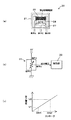
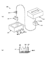
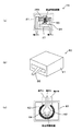
図1(a)は、本例のスイッチ装置を構成するスイッチ本体20(可変抵抗)を示す水平断面図であり、図1(b)は同スイッチ装置の回路図であり、図1(c)は同スイッチ装置の出力変化特性(操作ノブのストロークと出力電圧の関係)を示す図である。また、図2(a)は、スイッチ本体20の分解斜視図であり、図2(b)は、スイッチ本体20の縦断面図(上ケース等を外した状態)である。
なお、操作ノブや節度感生成手段の構成は、従来の構成(例えば、特許文献1に記載された構成)と同様でよいので、図示及び説明を省略する。
【0030】
スイッチ本体20は、基板上に実装可能となるようモジュール化されたものであり、図2(a)に示すように、合成樹脂製の下ケース21及び上ケース22と、これらケース内に移動自在に収納される合成樹脂製のスライダ23と、このスライダ23の内部下面側に装填される可動接点24と、この可動接点24とスライダ23の間に配置されて可動接点24を下方に付勢するコイル状のバネ25とを備える。また、下ケース21内の底面上には、図1(a)又は図2(b)に示すように、印刷抵抗26と、固定接点27と、端子A,B,Cとが、インサート成形等によって形成されている。
【0031】
ここで、スライダ23には、上ケース22の上面外方に突出する押圧部23aが形成され、操作ノブの下端側に一体に形成された可動片(図示省略)がこの押圧部23aに係合するようになっており、操作ノブを操作すると、この可動片がこの押圧部23aを押して、スライダ23や可動接点24が図1(a)において左右方向(印刷抵抗26の長手方向)に移動するようになっている。なおこの場合、操作ノブが中立位置にあるときには、可動接点24が印刷抵抗26の中央に位置し、操作ノブが引き上げ方向に操作されると可動接点24が中央位置から例えば左に、押し込み方向に操作されると可動接点24が中央位置から例えば右に変位する構成となっている。
また、端子A,B,Cの接続端部は、図2(a)及び(b)に示すように、下ケース21の側面から外方に向かって突出した状態(基板のスルーホールに対して挿入可能な状態)となっており、スイッチ本体20が容易に基板に実装可能となっている。
【0032】
また、図1(a)に示すように、印刷抵抗26は、この場合一定幅の帯状のものであり、固定接点27は、印刷抵抗26と平行に配置されたやはり一定幅の帯状の導体である。
また可動接点24は、バネ25に付勢されて印刷抵抗26と固定接点27の両方に接触しており、操作ノブの動作に伴って左右にスライドする際にも、印刷抵抗26と固定接点27の両方に接触しながら移動する。
また端子Aは、印刷抵抗26の一端に接続されており、端子Bは、印刷抵抗26の他端に接続されている。また端子Cは、固定接点27と一体に形成された端子である。
そして、このスイッチ本体20は、可動接点24の印刷抵抗26への接触が局部的とされて、この接触位置が可動接点24の移動に伴って変位することによって、端子AC間又はBC間の抵抗値が変化するようになっており、これにより、本発明の検出手段を構成する可変抵抗を実現している。
【0033】
次に、本例のスイッチ装置の回路構成は、図1(b)に示す構成となっている。
即ち、端子Aが電源ライン(例えば、5V)に接続され、端子Bがグランドに接続され、端子Cが制御部30の信号入力端子に接続されている。このような回路構成であると、前述した抵抗値の変化が電圧変化(例えば、0Vから5Vの範囲内の変化)に変換されて端子Cから出力され、この端子Cから出力される出力電圧(検出手段の出力値)が、図1(c)に示す如く、操作ノブのストロークに対してリニアに変化する良好な特性となる。
なお、操作ノブが揺動するタイプの場合、操作ノブの揺動角度と前記可動接点23の変位量とは、厳密にはリニアな関係にないため、このような非線形性を考慮すれば、図1(c)のグラフは正確にはリニアな特性にならないが、このような非線形成分は通常僅かであるため無視できる。ちなみに、印刷抵抗26の幅寸法を長手方向(可動接点24のスライド方向)に変化させて、操作ノブのストローク(揺動角度)と可動接点23の変位量の関係における上述した非線形成分を打ち消すことにより、よりリニアな特性を得ることも容易に可能である。
【0034】
また、制御部30は、例えばマイクロコンピュータなどの処理手段と、操作判定のための基準値を書き換え可能に記憶するEEPROMなどのメモリ(記憶手段)と、端子Cの電圧をデジタル値に変換するコンバータなどを有する制御回路であり、本発明の記憶手段と操作判定手段を構成する要素である。本例の場合、この制御部30は、パワーウインド駆動制御用の制御処理部としても機能する構成となっている。
【0035】
即ち、制御部30には、各操作方向それぞれについて、基準値V1,V2が予め登録されている。図1(b)に示す回路構成の場合、操作ノブ引き上げ方向(アップ方向)の基準値V1,V2としては、例えば3V程度と4V程度の値が設定され、操作ノブ押し込み方向(ダウン方向)の基準値V1,V2としては、例えば2V程度と1V程度の値が設定されている。そして制御部30は、スイッチ本体20の出力値(端子Cの電圧)をこの基準値と比較することで操作内容を判定し、この操作判定の結果に基づいて前述のリレーを駆動して、ウインドのマニュアルアップ、オートアップ、マニュアルダウン、又はオートダウンの駆動制御を行う構成となっている。
例えば、スイッチ本体20の出力値が、アップ方向の基準値V1以上になると、マニュアルアップが指令されたと判定し、アップ方向の基準値V2以上になると、オートアップが指令されたと判定する。また、スイッチ本体20の出力値が、ダウン方向の基準値V1以下になると、マニュアルダウンが指令されたと判定し、ダウン方向の基準値V2以下になると、オートダウンが指令されたと判定する。
【0036】
なお、各操作方向の基準値V1,V2は、部品の寸法精度や位置決め精度のばらつきを吸収するかたちで、以下のような手順で容易に最適値に設定できる。すなわち、操作ノブやスイッチ本体20を実際に組み付けた状態で、操作ノブを実際に操作しつつ上記出力値(端子Cの電圧)や操作力を計測し、アップ方向とダウン方向のそれぞれについて、1段目の節度感が生じた直後の出力値を基準値V1とし、2段目の節度感が生じた直後の出力値を基準値V2とすればよい。
【0037】
以上説明した本例のスイッチ装置を含むパワーウインドの駆動装置によれば、操作ノブの操作状態(操作方向及び操作量)に応じた出力値(端子Cの電圧)が制御部30に入力されて、従来と同様のウインドの駆動制御が実現される。
そして、本例のスイッチ装置によれば、製品毎のばらつきを吸収するように、必要に応じて製品毎に記憶手段の基準値V1,V2を書き換えることによって、実際に操作ノブが節度感のピーク位置以降に操作された時点で、制御部30(操作判定手段)が的確にそれを判定するように調整すること(即ち、節度感と操作結果のマッチングを的確にとること)が容易に可能である。このため、従来に比べて部品の制作精度や組み付け精度を高めなくてもよくなり、生産性向上やコスト低減が図れる。
【0038】
また、可変抵抗よりなる検出手段を使用し、良好な出力特性(リニアな特性)が得られるため、前述の特許文献1のような問題がない。
また、可変抵抗はホール素子に比べると周囲温度の影響を受け難いため、温度補償を行わなくても周囲温度変化による誤動作を防止できる利点もある。
また本例では、操作段数が各操作方向に複数あるにもかかわらず、スイッチ本体20は端子数が3個で、摺動式の接点が1式の簡素な構成であるため、生産性向上やコスト低減及び小型化に貢献できるという効果も得られる。
また本例では、可変抵抗を構成するスイッチ本体20が、基板上に実装可能となるようモジュール化されている態様であるから、設計の標準化や大量生産によるコストダウンが容易になるとともに、部品の管理や組み立て作業が容易になる効果もある。
【0039】
(第2形態例)
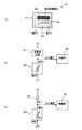
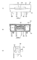
次に、本発明の第2形態例について、図3により説明する。図3(a)は、本例のスイッチ装置におけるスイッチ本体40を示す水平断面図であり、図3(b)及び(c)は同スイッチ装置の回路図である。なお以下では、第1形態例と同様の構成要素には、同符号を使用して説明を省略する。
本例のスイッチ本体40は、図3(a)に示すように、第1形態例のスイッチ本体20において端子Bを削除した構成となっている点に特徴を有し、他の構成はスイッチ本体20と同様である。
【0040】
なお、本例のスイッチ装置の回路構成は、例えば図3(b)に示すように、端子Aが定電流回路41を介して電源ラインに接続され、端子Bがグランドに接続された構成でもよいし、図3(c)に示すように、端子Aが分圧用抵抗42を介して電源ラインに接続され、端子Bがグランドに接続された構成でもよい。
ここで、定電流回路41は、スイッチ本体40の抵抗(可変抵抗)を流れる電流値を一定に保持する回路であり、公知の回路構成や素子を使用したもの(例えば、定電流ダイオードよりなるもの)を使用することができる。但し、この定電流回路41としては、周囲温度によって特性が変化し難い回路を使用すべきである。
【0041】
このような回路構成であると、スイッチ本体40の抵抗値の変化が電圧変化に変換されて端子Aから出力され、この端子Aから出力される出力電圧(検出手段の出力値)が、図1(c)に示す如く、操作ノブのストロークに対してリニアに変化する良好な特性となる。
なお、図3(c)に示す構成では、分圧用抵抗42の抵抗値をR1とし、スイッチ本体40の抵抗値をR2とすると、出力電圧V=5×R2/(R1+R2)となり、操作ノブのストロークと抵抗値R2の関係がリニアな特性でも、厳密にはリニアな特性(ストロークと出力電圧の関係)は得られないが、抵抗値R1を十分大きな値に設定することにより、ほぼリニアな特性が得られる。また、印刷抵抗26の幅寸法を長手方向(可動接点24のスライド方向)に変化させて、抵抗値R2と出力電圧Vの関係における上述した非線形性を打ち消すことにより、十分リニアな特性を得ることも容易に可能である。
【0042】
以上説明した本例のスイッチ装置でも、第1形態例と同様の効果が得られる。特に本例の場合には、スイッチ本体40の端子が2個でよいため、スイッチ本体のさらなる生産性の向上やコスト低減等が実現できる。
【0043】
(第1展開例)
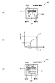
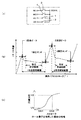
次に、本発明から展開された技術である展開例について説明する。まず第1展開例について、図4(a),(b)により説明する。図4(a)は、本例のスイッチ装置におけるスイッチ本体45を示す水平断面図であり、図4(b)は同スイッチ装置の特性を示す図である。
本例のスイッチ本体45は、図4(a)に示すように、第2形態例のスイッチ本体40において、印刷抵抗26の代わりに、幅寸法が一定でない印刷抵抗26aを設けた点に特徴を有し、他の構成はスイッチ本体40と同様である。回路構成についても、第2形態例と同様でよい。
【0044】
ここで、印刷抵抗26aは、図4(b)のようなより好ましい特性が得られるように、幅寸法が長手方向において変化する形状となっている。物体の抵抗値は、幅寸法(断面積)に反比例するため、このように印刷抵抗26の幅寸法を変化させることによって、任意の特性が得られる。ここで図4(b)に示す特性は、各オン点(ON1,ON2)を設定する領域において特に出力電圧の変化が大きくなるような特性(即ち、操作判定に使用される領域において検出感度が高くなるような特性)であり、このような特性が設定できると、操作ノブの操作をより高感度に判定することが効果的かつ効率的に実現できるようになり、全体の印加電圧の増加を抑制しつつ、スイッチ操作の信頼性をより高めることができる。
【0045】
(第2展開例)
次に、第2展開例について、図4(c)により説明する。図4(c)は、本例のスイッチ本体50を示す水平断面図である。
本例のスイッチ本体50は、図4(c)に示すように、第2形態例のスイッチ本体40において、印刷抵抗26の代わりに、中央部が可動接点24と接触しない形状の印刷抵抗26bを設けた点に特徴を有し、他の構成はスイッチ本体40と同様である。回路構成についても、第2形態例と同様でよい。
【0046】
ここで、印刷抵抗26bは、操作ノブが中立位置(非操作位置)にあるときに、可動接点24との接続状態がオフするものである。即ち、本例のスイッチ本体50(可変抵抗)は、操作ノブが非操作位置にあるときに、その抵抗値が極大(無限大)になる構成である。
このような構成であると、抵抗値の変化を電圧変化に変換するためにスイッチ本体に流さなければならない電流値が、非操作状態においてゼロとなり、非操作状態での消費電流(即ち、暗電流)をゼロとすることができる。
【0047】
(第3展開例)
次に、第3展開例について、図5(a)により説明する。図5(a)は、本例のスイッチ本体55を示す水平断面図である。
本例のスイッチ本体55は、図5(a)に示すように、第2形態例のスイッチ本体40において、印刷抵抗26の代わりに、中央部が可動接点24と接触しない形状の印刷抵抗26bを設けるとともに、この印刷抵抗26bの中央部に抵抗値が印刷抵抗26bよりも格段に高い印刷抵抗56を設けた点に特徴を有し、他の構成はスイッチ本体40と同様である。回路構成についても、第2形態例と同様の構成(図3(c)の構成)でよい。
【0048】
本例のスイッチ本体50(可変抵抗)は、操作ノブが非操作位置にあるときに、その抵抗値が極大(他の状態に比べて格段に高い状態)になる。
このため、抵抗値の変化を電圧変化に変換するためにスイッチ本体に流さなければならない電流値が、非操作状態において極小(他の状態に比べて格段に低い状態)となり、非操作状態での消費電流(即ち、暗電流)を低減することができる。
また本例の態様は、前述の第2展開例の態様に比較して、次のような固有の効果を有する。即ち、前述の第2展開例の態様では、非操作状態において、端子Aと端子Cとの間の導通がなくなるので、回路の断線検出を行うことが容易にできなくなる。しかし、この第3展開例の態様では、非操作状態での消費電流を低減できるとともに、非操作状態での断線検出も容易に可能である。
というのは、前述の第2展開例では、非操作状態においてスイッチ本体の通電ラインが遮断されるため、非操作状態において制御部30に出力される電圧は、前記通電ラインの断線が起こった場合とかわりなく、制御部30の機能によってスイッチ本体からの出力電圧に基づいて断線を判別することができない。しかし、この第3展開例の態様では、非操作状態でも印刷抵抗56を介して微弱な電流が流れているため、例えば図3(c)に示す回路において制御部30に出力される電圧は、分圧抵抗R1の電圧降下の分だけ電源電圧(5V)よりも低い値になっている。これに対して、例えば、スイッチ本体の通電ラインにおける断線が発生した場合には、制御部30に出力される電圧は、電源電圧又はグランド電位となる。このため、制御部30の機能によって、このような電圧の違いに基づいて、非操作状態においても断線を検出することが可能となるからである。なお、前述の第2形態例等の態様であっても、同様の断線検出が可能であることはいうまでもない。
【0049】
(第4展開例)
次に、第4展開例について、図5(b),(c)により説明する。図5(b)は、本例のスイッチ本体60を示す斜視図であり、図5(c)は、スイッチ本体60を示す水平断面図である。
本例のスイッチ本体60は、原理的には、第1形態例のスイッチ本体20と同様ものであるが、ロータリ式である点に特徴を有する。
即ち、スイッチ本体60は、ケース61の内部に、円形の固定接点62と、この固定接点62の周囲を囲むように配置されたリング状の印刷抵抗63と、固定接点62及び印刷抵抗63に接触しつつ回転運動する可動接点64とを備える。そして、ケース61から一端が突出する可動アーム65を有し、この可動アーム65を介して操作ノブの揺動が可動接点64に伝達され、操作ノブの揺動に伴って可動接点64が回転運動する構成となっている。また、印刷抵抗63の一端に接続された端子Aと、印刷抵抗63の他端に接続された端子Bと、固定接点62に接続された端子Cとが、接続端部をケース61の外方に突出させた状態で設けられている。
このような構成のスイッチ本体60によっても、第1形態例のスイッチ本体20と同様の動作が実現でき、第1形態例と同様の効果が得られる。しかもこの場合には、操作ノブのストロークと可動接点64のストローク(抵抗値の変化)との関係がリニアであるため、最終的な出力特性をより好ましい特性にすることが特に容易であるという特有の利点がある。
【0050】
(第5展開例)
次に、第5展開例について、図6(a)により説明する。図6(a)は、本例のスイッチ本体70を示す水平断面図である。
本例のスイッチ本体70は、操作ノブの動作速度に応じた頻度でパルス信号を生成するパルス発生器を構成するもので、図6(a)に示すように、端子Aに接続された帯状の固定接点71と、端子Bに接続された櫛刃状の固定接点72と、操作ノブの動作に伴って左右にスライドする可動接点24とよりなる。
ここで、固定接点71は、長手方向が左右方向(可動接点24のスライド方向)となるように配置され、また固定接点72は、この固定接点71と平行に配置され、固定接点72の櫛刃状部分が固定接点71に沿って配置された構成となっている。そして、可動接点24は、横長の固定接点71に常に接触しているが、固定接点72に対しては、その櫛刃状部分において接触するため、操作ノブの動作に伴って接続状態と非接続状態を一定間隔で交互に繰り返す構成(オンオフを繰り返す構成)となっている。
【0051】
このため、例えば端子Aに電源電圧を印加し、端子Bの電圧をスイッチ本体70の出力とすれば、この出力は、操作ノブの動作速度に応じた頻度のパルス信号となる。
したがって、このパルス信号を制御回路30に入力し、このパルス信号の出力回数(パルス数)をスイッチ本体70の出力値として操作判定に使用するようにすれば、第1形態例と同様の動作が可能であり、同様の作用効果が得られる。
【0052】
即ち、操作ノブやスイッチ本体70を実際に組み付けた状態で、操作ノブを実際に操作しつつ上記出力値(パルス数)や操作力を計測し、アップ方向とダウン方向のそれぞれについて、1段目の節度感が生じた直後の出力値を基準値V1とし、2段目の節度感が生じた直後の出力値を基準値V2として登録しておく。そして稼動時には、制御部30において、このように設定した基準値と上記出力値を比較することに基づいて操作判定し、この操作判定結果に基づく制御を実行する構成とすれば、第1形態例と同様の動作が可能であり、同様の作用効果が得られる。特に本形態例の場合には、周囲温度の影響を全く受けないスイッチ装置が実現できる。
なお本例の場合、操作ノブの絶対位置を検出することができないので、原点(例えば中立位置)を制御部30において把握することが必要となるが、非操作状態において操作ノブがバネの復元力によって中立位置に自動復帰する構成であれば、このような原点の把握は容易に可能である。例えば、装置の電源投入後に制御部30が起動した直後の操作ノブの位置が中立位置であると把握すればよいからである。
【0053】
(第6展開例)
次に、第6展開例について、図6(b)により説明する。図6(b)は、操作ノブ75と本例のスイッチ本体80とを示す側面図である。なお、符号76は、操作ノブ75を支持する水平軸であり、符号77は、操作ノブ75の下端側に設けられた可動片を示す。
本例のスイッチ本体80は、可動片77の両側に配置される圧電素子81,82と、可動片77と各圧電素子81,82の間に介装された例えばコイル状のバネ83,84とを備えるものである。
本例のスイッチ本体80では、操作ノブ75の揺動に伴う可動片77の変位量に比例した力が圧電素子81,82に入力されるため、各圧電素子81,82の出力電圧は、操作ノブ75のストロークに対してリニアに変化する特性となる。
したがって、この出力電圧を制御回路30に入力し、この出力電圧をスイッチ本体80の出力値として操作判定に使用するようにすれば、やはり第1形態例と同様の動作が可能であり、同様の作用効果が得られる。
【0054】
なお、図6(c)は、節度感(操作力のピークを有する特性)を持たない構成を示している。本発明をこのような構成に展開させることもできる。節度感のないスイッチでも、一般的には、特定の操作位置において、特定の操作結果が生じるようにマッチングをとる必要があるからである。例えば、空調機の温度調節用の操作ノブでは、温度目盛に対して適合した操作位置で、その温度を指令するスイッチ出力が生じる必要がある。この図6(c)は、操作段が2段の場合を示しているが、1段の場合も当然あり得る。
【0055】
【発明の効果】
本発明のスイッチ装置によれば、製品毎のばらつきを吸収するように、必要に応じて製品毎に記憶手段の基準値を書き換えることによって、実際に操作ノブが特定の操作位置以上に(例えば、節度感のピーク位置以降に)操作された時点で、操作判定手段が的確にそれを判定するように調整すること(即ち、操作位置と操作結果のマッチングを的確にとること)が容易に可能である。このため、従来に比べて部品の制作精度や組み付け精度を高めなくてもよくなり、生産性向上やコスト低減が図れる。
しかも、出力値変化の飽和が生じない検出手段によって操作ノブの動作を検出しているため、前述の特許文献1の場合と異なり、良好な特性(少なくともリニアな特性)が容易に得られる。
また、検出手段が可変抵抗によって構成されるものであるため、周囲温度の影響を受け難く、温度補償を行わなくても周囲温度変化による誤動作を防止できる利点もある。
【図面の簡単な説明】
【図1】 スイッチ装置(第1形態例)の要部構成や特性を説明する図である。
【図2】 スイッチ装置(第1形態例)のスイッチ本体を示す図である。
【図3】 スイッチ装置(第2形態例)の要部構成を説明する図である。
【図4】 スイッチ装置(第1、第2展開例)の要部構成や特性を説明する図である。
【図5】 スイッチ装置(第3、第4展開例)の要部構成を説明する図である。
【図6】 スイッチ装置(第5、第6展開例)の要部構成等を説明する図である。
【図7】 従来のスイッチ本体を示す図である。
【図8】 従来のスイッチ装置を説明する図である。
【符号の説明】
20,40,45,50,55,60 スイッチ本体(検出手段、可変抵抗)
30 制御部(記憶手段、操作判定手段)
70 スイッチ本体(検出手段、パルス発生器)
80 スイッチ本体(検出手段)[0001]
BACKGROUND OF THE INVENTION
The present invention relates to a switch device for opening and closing a power window of a vehicle, and more particularly to a switch device capable of easily adjusting the matching between an operation position and an operation result, and a drive device such as a power window using the switch device.
[0002]
[Prior art]
In general, a drive device such as a power window system or a sunroof system of a vehicle is provided with a switch device having a feeling of moderation (click feeling). It is configured to control the opening / closing operation. In addition, this type of device realizes automatic window operation (operation that automatically moves the window to the fully closed position or fully opened position even if the user stops operation), automatic reversal operation when pinching is detected (pinching prevention operation), etc. Electronic control is becoming the mainstream, and a drive system using a relay is common.
That is, as described in Patent Document 1, this type of device supplies power to the motor to drive the motor in the opening direction (direction of opening the window) or the closing direction (direction of closing the window), respectively. Two small relays (having a so-called 1c contact), a small switch for instructing the operation of the motor (operation of the opening / closing body) according to the user's operation, and depending on the operating state of the switch A control circuit (not shown) for driving any one of the relays. For example, in a state where these elements are mounted on one board, they are installed in an empty space such as the interior of the vehicle door (the back side of the window operation unit).
[0003]
Here, the relay (not shown) includes an exciting coil, a common terminal (hereinafter referred to as C terminal), a normally open (normally open) terminal (hereinafter referred to as NO terminal), and a normally closed (respectively). Normally closed) terminal (hereinafter referred to as NC terminal), and in a non-operating state where the coil is not energized, the C terminal and N.C. In a state where the C terminal is connected and the coil is energized, the C terminal and the N.C. The O terminal is connected. Usually, the N. The O terminal is connected to the high potential side of the power supply line. The C terminal is connected to the ground side (the low potential side of the power supply). The C terminal of the open side relay is connected to the terminal on the side where the motor rotates in the open direction when connected to the high potential power source side of both terminals of the motor coil of the motor. On the other hand, the C terminal of the relay on the closing side is connected to the terminal on the side where the motor rotates in the closing direction when it is connected to the high potential power source side of both terminals of the motor coil of the motor.
[0004]
And the said switch becomes a structure operated by the operation knob (illustration omitted) arrange | positioned at the elbow rest etc. of a vehicle door, for example. This operation knob is normally swingable from the neutral position (non-operation position) in the pulling direction (the direction commanding the closing of the window) and the pushing direction (the direction commanding the opening of the window). 1 is given a moderation feeling of one or two stages. For example, an operation knob for a window with an auto operation function commands a manual operation (operation that is not an auto operation) by an operation that can provide a sense of moderation at the first stage, and an auto operation by an operation that provides a sense of moderation at the second stage. For example, as shown in FIG. 8B, two levels of moderation are given in each direction, and the number of operation steps is two in each direction. In addition, the operation knob for windows without auto operation function gives a manual operation by the operation that can obtain the first level of moderation, so that one level of moderation is given in each direction, and the number of operation steps is in each direction. It is one step.
[0005]
In addition, as a means (moderation feeling production | generation means) which generate | occur | produces the above-mentioned moderation feeling, there exist some which consist of a spring and a cam mechanism as described in patent document 1, for example.
That is, a cylindrical portion that is integrally formed with the operation knob and that extends downward and opens at the lower end, a sliding member that is loaded in the cylindrical portion and is slidable in the axial direction of the cylindrical portion, A coil spring that is loaded on the back side (upper side) of the sliding member and biases the sliding member downward, and is fixed to a fixed side (for example, an
Here, the shape of the fitting surface of the recess of the receiving member and the tip of the sliding member is such that the operating knob is in a predetermined neutral position (non-operating position) by the restoring force of the coil spring in a natural state (a state where no external force is applied). It has a conical shape as a whole so that it can be restored and maintained in that position. In addition, when viewed locally, these fitting surfaces have a shape with irregularities (steps) so that a feeling of moderation occurs in one or two steps when the operation knob is swung in each direction. Yes.
[0006]
Moreover, the said switch is comprised as a switch module as shown, for example with the code |
The
These terminals are incorporated in the circuit so that the voltage changes according to the ON / OFF operation of the corresponding contact, and this voltage change is input to the control circuit as an operation signal. For example, the common terminal (COMA) is connected to the ground, and the other terminals (AU, AD, MU, MD) are connected to predetermined input terminals of the control circuit, and via a pull-up resistor (not shown). Connected to the high potential side of the power supply. As a result, when one of the contacts is turned on, the voltage at the other terminal (output terminal) of the contact changes from a high potential (power supply potential) to a low potential (ground side potential), thereby causing the control circuit to switch to that terminal. The system reads when a corresponding signal is input.
[0007]
The
Here, the
[0008]
Further, from the
In addition, the
[0009]
The dimensions and positions of the members are set so that the operating state of each contact of the
In other words, at the angular position (the position of the first stage end shown in FIG. 8B) after the operation knob is swung in the pulling direction and the first-stage moderation feeling in this direction is generated, the
[0010]
[Patent Document 1]
JP 2001-118465 A
[0011]
[Problems to be solved by the invention]
By the way, it is difficult for the switch in the conventional driving device described above to match the operating state (operation result) of each contact with a sense of moderation (that is, a specific operation position), thereby improving productivity and reducing costs. There was a limit. In particular, in recent years, in the field of vehicles and the like, the total stroke of the operation knob tends to be limited as a market demand for reasons such as ease of operation and high-grade feeling. Specifically, for example, the swing stroke of the operation knob has conventionally been about 20 ° as a whole, but in recent years, it has been desired to shorten it to about 10 °. For this reason, it is very difficult to perform the matching, and there is a problem that a decrease in productivity and an increase in cost are unavoidable.
[0012]
This is because, for example, in the case of the
In order to achieve the above-described matching, the manual
[0013]
However, the above-described peak position and end position are not actually constant values, but vary from product to product due to production errors or assembly errors of parts that generate an operation knob or moderation. Therefore, in actuality, in consideration of such variations, for example, it is necessary to place the position where each contact is turned on (on point) within a narrower setting allowable range exemplified in FIG. 8B. However, since the ON point of each contact also naturally varies depending on the accuracy of each component constituting the
[0014]
In addition, with the conventional switch configuration consisting of contacts that turn on and off as described above, the number of contacts and the number of terminals increase according to the number of operation stages, so the number of parts increases when the number of operation stages is large. There was a problem that there was a limit to productivity improvement and cost reduction. For example, the above-described
[0015]
In the above-mentioned Patent Document 1 disclosed by the applicant, a movable piece (magnetic field generating means) provided integrally with the operation knob and a position where the movable piece approaches as the operation knob moves are arranged. A magnetic sensor (for example, a hall element) constitutes a detection means for detecting the operation amount and the operation direction of the operation knob in a non-contact manner, and an output value of the detection means (that is, an output voltage of the hall element) is stored as a reference. A switch device that performs an operation determination based on comparison with a value is described. According to this switch device, by setting the reference value for each product, it is possible to absorb the variation for each product and perform the above-described matching. Also, when the number of operation stages is large, the configuration of the switch module is simplified and the number of parts can be reduced, which can contribute to solving the above-described conventional problems. However, in this case, there were the following problems to be solved.
[0016]
That is, the change characteristic of the output voltage (output value of the detection means) of the magnetic sensor such as the Hall element with respect to the stroke of the operation knob (advancement / retraction operation of the movable piece) is actually bi-directional as shown in FIG. (The direction in which the movable piece approaches the Hall element and the direction in which the movable piece moves away from the Hall element) tends to saturate, and the change characteristic of such a tendency depends only on the positional relationship between the Hall element and the movable piece. There is a problem that it is difficult to set a preferable characteristic because the degree of freedom is fixed.
[0017]
Specifically, for example, as in the case of the
[0018]
In addition, since the Hall element is easily affected by the ambient temperature in the configuration using the Hall element as described above, the characteristic change due to the temperature is large, and the malfunction due to the influence of the temperature is surely prevented. For this purpose, a temperature compensation circuit using a thermistor or the like must be provided, and there is a problem that sufficient cost reduction cannot be achieved.
Therefore, the present invention can easily match the operation position and the operation result, and can easily set a good characteristic, and more preferably, a simple and low-cost switch device that is hardly affected by temperature change. And it aims at providing the drive device which uses such a switch apparatus.
[0019]
[Means for Solving the Problems]
The switch device of the present application isDesigned to create a sense of moderation at specific operating positionsAn operation knob and detection means capable of generating an output value that continuously changes in accordance with the operation of the operation knob, the detection means not causing saturation of the output value change, and a predetermined valuepluralThe reference value for operation judgmentRespectivelyStorage means for storing; andpluralControl means for registering a reference value in the storage means, output value of the detection means and the storage means stored in the storage meanspluralOperation determining means for determining that the operation knob has been operated beyond a specific operation position based on a magnitude relationship with a reference value, and the detection means is movable to move as the operation knob moves. It is composed of a variable resistor consisting of a contact and a printing resistor that is always connected to this movable contact, and the change in the resistance value of this variable resistor is converted into a voltage change, and this voltage change is output as the output value. There is a characteristic that a contact position between the movable contact and the printing resistance is linearly displaced with the movement of the operation knob, and the resistance value and the output value are linearly changed with the displacement. The control means is stored in the storage means by user input.pluralRewrite the reference valueRepeat for each reference value,The operation determination means is the rewrittenpluralA function for performing the determination by comparing a reference value with the output value is provided.And
There are a plurality of the specific operation positions within the operation range of the operation knob, the moderation feeling is generated for each operation position, the reference value is stored for each operation position, and the operation determination means Each of the determinations corresponding to the operation position is performed.
The present invention isSwitch device that creates a sense of moderation at a specific operating positionIt is.This is because such a switch device, like the switch device of the power window system described above, is strongly required to easily match the operation position and the operation result and to have good switch characteristics.
[0020]
Here, the “moderate feeling” is a so-called click feeling, and the operating force necessary to operate the operating knob increases at a specific operating position (peak position) to form a peak of operating force. Then, when the operating force is reduced to a predetermined end position, it is a feeling of touch given to the user who operates the operation knob, and the user feels that the operation has been executed, and the operation when the operation knob is operated. This ensures the reliability of the operation.
Also, “continuous depending on the operation of the operation knobIn"Detection means that can generate a changeable output value and does not cause saturation of change in output value" means that the change characteristic of the output value with respect to the stroke (operation amount) of the operation knob is at least linear. Means easy detection meansAndThe meaning does not include a magnetic sensor such as the Hall element described in Patent Document 1 described above.In this application, it is constituted by a variable resistor.
[0021]
Further, as a specific aspect of “determining that the operation knob is operated beyond a specific operation position based on the magnitude relationship between the output value of the detection unit and the reference value stored in the storage unit”. Is a mode in which it is determined that the operation is performed when the output value is increased above the reference value or exceeds the reference value, and a mode in which it is determined that the operation is performed when the output value is lower than the reference value or lower than the reference value. There is.
Also, “determining that the operation knob has been operated beyond a specific operation position” means an operation command for an operation stage corresponding to the operation position (for example, an operation signal input for instructing opening and closing of an opening / closing body) ) Is determined, and in the case where a sense of moderation is generated at a specific operation position, this means that it is determined that an operation command for the operation stage corresponding to the sense of moderation has been issued. .
[0023]
According to this switch device, when the operation knob is actually operated after a specific operation position by rewriting the reference value of the storage means for each product as necessary so as to absorb the variation between products. It is possible to easily adjust the operation determination means so as to accurately determine it (that is, to accurately match the operation position with the operation result). For this reason, it is not necessary to increase the production accuracy and assembly accuracy of parts compared to the conventional case, and productivity can be improved and costs can be reduced.
In addition, since the operation of the operation knob is detected by the detection means that does not cause saturation of the output value change, unlike the case of the above-mentioned Patent Document 1, a good characteristic (at least linear characteristic) can be easily obtained.
Also,Since the detection means is constituted by a variable resistor,There is also an advantage that malfunctions due to changes in the ambient temperature can be prevented without temperature compensation without being affected by the ambient temperature.
[0025]
Further, a more preferable aspect of the switch device is at least the variable resistor.But,It is an aspect that is modularized so that it can be mounted on a substrate. Such an aspect facilitates cost reduction by design standardization and mass production, and also facilitates component management and assembly work.
[0026]
In addition, this switch device may be one in which the operation knob is operated only in one direction, or one in which the feeling of moderation is only in the first stage (the number of operation stages is one). A moderation feeling is provided to input an operation command for each direction, or a moderation feeling is provided in two or more stages and different operation commands are input in two or more stages (the number of operation stages is two or more. ).
That is, this switch deviceSaidThe operation knob is operated in both directions around the non-operation position, and there is at least one specific operation position in the operation range in each direction, and the sense of moderation is provided for each operation position in each direction. And the reference value is stored for each operation position in each direction, and the operation determination means performs the determination corresponding to the operation position in each direction.
[0027]
As described above, when a plurality of moderation feelings are set and there are a plurality of operation steps corresponding to each moderation feeling, the switch device as in the present application has a simplified and lower switch body than the conventional contact type switch. Cost can be reduced. In this case, in the conventional contact type switch, as described above, a plurality of contacts and terminals must be provided. However, in the switch device of the present application, even if the number of operation stages is increased, only one detection means is required. This is because the output terminal may be one set (the number of terminals is two or three).
[0028]
The switch device of the present application is suitable as a switch of a drive device that performs drive control of an electric device such as a power window in a vehicle. Even if the switch stroke is shortened, the matching between the operation position and the operation result is achieved accurately, and a highly reliable drive operation is possible. Therefore, the product value can be improved without problems by shortening the switch stroke. This is because it can contribute to cost reduction of the driving device.
[0029]
DETAILED DESCRIPTION OF THE INVENTION
Hereinafter, embodiments of the present invention will be described with reference to the drawings.
(First embodiment)
First, a first embodiment of the present invention (a switch device for driving a power window) will be described with reference to FIGS.
FIG. 1A is a horizontal sectional view showing a switch body 20 (variable resistor) constituting the switch device of this example, FIG. 1B is a circuit diagram of the switch device, and FIG. FIG. 4 is a diagram showing output change characteristics (relationship between operation knob stroke and output voltage) of the switch device; 2A is an exploded perspective view of the
Note that the configuration of the operation knob and the moderation sensation generating means may be the same as the conventional configuration (for example, the configuration described in Patent Document 1), and thus illustration and description thereof are omitted.
[0030]
The
[0031]
Here, the
Further, as shown in FIGS. 2A and 2B, the connection end portions of the terminals A, B, and C protrude outward from the side surface of the lower case 21 (with respect to the through holes of the substrate). The
[0032]
In addition, as shown in FIG. 1A, the
The
The terminal A is connected to one end of the
The
[0033]
Next, the circuit configuration of the switch device of this example is the configuration shown in FIG.
That is, the terminal A is connected to a power supply line (for example, 5 V), the terminal B is connected to the ground, and the terminal C is connected to the signal input terminal of the
In the case of a type in which the operation knob swings, the swing angle of the operation knob and the displacement amount of the
[0034]
Further, the
[0035]
That is, the reference values V1 and V2 are registered in advance in the
For example, when the output value of the
[0036]
The reference values V1 and V2 for each operation direction can be easily set to optimum values by the following procedure in order to absorb variations in the dimensional accuracy and positioning accuracy of the parts. That is, in the state where the operation knob and the
[0037]
According to the power window drive device including the switch device of this example described above, an output value (voltage at the terminal C) corresponding to the operation state (operation direction and operation amount) of the operation knob is input to the
Then, according to the switch device of this example, the operation knob is actually peaked in moderation by rewriting the reference values V1 and V2 of the storage means for each product as necessary so as to absorb the variation for each product. It can be easily adjusted so that the control unit 30 (operation determination unit) accurately determines it when operated after the position (that is, the moderation feeling and the operation result are accurately matched). is there. For this reason, it is not necessary to increase the production accuracy and assembly accuracy of parts as compared with the conventional case, and productivity can be improved and costs can be reduced.
[0038]
In addition, since a good output characteristic (linear characteristic) can be obtained by using a detection means including a variable resistor, there is no problem as in the above-mentioned Patent Document 1.
In addition, since the variable resistor is less susceptible to the influence of the ambient temperature than the Hall element, there is an advantage that malfunction due to a change in the ambient temperature can be prevented without performing temperature compensation.
Further, in this example, although there are a plurality of operation steps in each operation direction, the
In this example, since the
[0039]
(Second embodiment)
Next, a second embodiment of the present invention will be described with reference to FIG. FIG. 3A is a horizontal sectional view showing the
As shown in FIG. 3A, the
[0040]
Note that the circuit configuration of the switch device of this example may be a configuration in which the terminal A is connected to the power supply line via the constant
Here, the constant
[0041]
With such a circuit configuration, the change in the resistance value of the
In the configuration shown in FIG. 3C, when the resistance value of the
[0042]
The switch device of the present example described above can achieve the same effects as those of the first embodiment. In particular, in the case of this example, since only two terminals of the
[0043]
(First development example)
Next, from the present inventionA development example that is a developed technology will be described. First example of deploymentWill be described with reference to FIGS. FIG. 4A is a horizontal sectional view showing the
As shown in FIG. 4A, the
[0044]
Here, the
[0045]
(Second development example)
next,Second development exampleWill be described with reference to FIG. FIG. 4C is a horizontal sectional view showing the
As shown in FIG. 4C, the
[0046]
Here, the
With such a configuration, the current value that must be passed through the switch body in order to convert the change in resistance value into a voltage change becomes zero in the non-operating state, and the current consumption in the non-operating state (that is, the dark current) ) Can be zero.
[0047]
(Third development example)
next,Third development exampleWill be described with reference to FIG. FIG. 5A is a horizontal sectional view showing the
As shown in FIG. 5A, the
[0048]
The switch body 50 (variable resistor) of this example has a maximum resistance value (a state that is significantly higher than other states) when the operation knob is in the non-operation position.
For this reason, the current value that must be passed through the switch body to convert the change in resistance value into a voltage change is minimal in a non-operation state (a much lower state than other states), and in a non-operation state Consumption current (that is, dark current) can be reduced.
In addition, the aspect of this example is as described above.Second development exampleCompared to this aspect, it has the following inherent effects. That is, the above-mentionedSecond development exampleIn this aspect, since the continuity between the terminal A and the terminal C is lost in the non-operating state, it becomes difficult to detect the disconnection of the circuit. But thisThird development exampleIn this aspect, current consumption in the non-operating state can be reduced, and disconnection detection in the non-operating state can be easily performed.
Because the aforementionedSecond development exampleThen, since the energization line of the switch body is interrupted in the non-operating state, the voltage output to the
[0049]
(Fourth development example)
next,Fourth development exampleWill be described with reference to FIGS. FIG. 5B is a perspective view showing the
The
That is, the
Also with the
[0050]
(Fifth development example)
next,Fifth development exampleWill be described with reference to FIG. FIG. 6A is a horizontal sectional view showing the
The switch
Here, the fixed
[0051]
Therefore, for example, if a power supply voltage is applied to the terminal A and the voltage at the terminal B is used as the output of the
Therefore, if this pulse signal is input to the
[0052]
That is, in the state in which the operation knob and the
In the case of this example, since the absolute position of the operation knob cannot be detected, it is necessary to grasp the origin (for example, the neutral position) in the
[0053]
(Sixth development example)
next,Sixth development exampleWill be described with reference to FIG. FIG. 6B is a side view showing the
The
In the
Therefore, if this output voltage is input to the
[0054]
In addition, FIG.6 (c)A configuration that does not have a modest feeling (a characteristic that has a peak in operating force)Show. The present invention can also be developed in such a configuration. This is because even a switch without moderation generally needs to be matched so that a specific operation result is produced at a specific operation position. For example, an operation knob for adjusting the temperature of an air conditioner needs to generate a switch output for instructing the temperature at an operation position suitable for the temperature scale. thisFIG. 6C shows a case where there are two operation stages, but there may naturally be one stage.
[0055]
【The invention's effect】
According to the switch device of the present invention, the operation knob is actually moved beyond a specific operation position by rewriting the reference value of the storage means for each product as necessary so as to absorb variations among products (for example, It is possible to easily adjust the operation determination means so that it can accurately determine it (ie after the peak position of moderation) (that is, to accurately match the operation position and the operation result). is there. For this reason, it is not necessary to increase the production accuracy and assembly accuracy of parts as compared with the conventional case, and productivity can be improved and costs can be reduced.
In addition, since the operation of the operation knob is detected by the detection means that does not cause saturation of the output value change, unlike the case of the above-mentioned Patent Document 1, a good characteristic (at least linear characteristic) can be easily obtained.
Also,Since the detection means is constituted by a variable resistor,There is also an advantage that malfunctions due to changes in the ambient temperature can be prevented without temperature compensation without being affected by the ambient temperature.
[Brief description of the drawings]
FIG. 1 is a diagram illustrating the configuration and characteristics of main parts of a switch device (first embodiment).
FIG. 2 is a diagram showing a switch body of a switch device (first embodiment).
FIG. 3 is a diagram illustrating a configuration of a main part of a switch device (second embodiment).
[Fig. 4] Switch device (First and second development examplesIt is a figure explaining the principal part structure and characteristic of ().
FIG. 5: Switch device (Third and fourth development examplesIt is a figure explaining the principal part structure of).
FIG. 6: Switch device (Fifth and sixth development examplesFIG.
FIG. 7 is a view showing a conventional switch body.
FIG. 8 is a diagram illustrating a conventional switch device.
[Explanation of symbols]
20, 40, 45, 50, 55, 60 Switch body (detection means, variable resistance)
30 control unit (storage means, operation determination means)
70 Switch body (detection means, pulse generator)
80 Switch body (detection means)
Claims (4)
この操作ノブの動作に応じて連続的に変化する出力値を生成可能な検出手段であって、出力値変化の飽和が生じない検出手段と、
予め定められた複数の操作判定の基準値をそれぞれ記憶する記憶手段と、
前記複数の基準値を前記記憶手段に登録する制御手段と、
前記検出手段の出力値と前記記憶手段に記憶された複数の基準値との大小関係に基づいて、特定の操作位置以上に前記操作ノブが操作されたことを判定する操作判定手段と、
を備え、
前記検出手段は、前記操作ノブの移動に伴って移動する可動接点と、この可動接点と常に接続している印刷抵抗とよりなる可変抵抗によって構成され、この可変抵抗の抵抗値の変化を電圧変化に変換し、この電圧変化を前記出力値として出力するものであり、前記操作ノブの移動に伴って前記可動接点と前記印刷抵抗との接触位置が直線的に変位し、この変位に伴って前記抵抗値及び前記出力値が直線的に変化する特性を有し、
前記制御手段は、ユーザの入力により前記記憶手段に記憶されている複数の基準値を書き換える操作をそれぞれの基準値に対して繰り返し、前記操作判定手段は、書き換えられた前記複数の基準値と前記出力値とを比較して前記判定を行う機能を有し、
前記特定の操作位置が前記操作ノブの動作範囲内に複数存在し、前記節度感が各操作位置毎に発生し、前記基準値が各操作位置毎に記憶されるとともに、前記操作判定手段が各操作位置に対応した前記判定をそれぞれ行なう構成であることを特徴とするスイッチ装置。 An operation knob configured to generate a sense of moderation at a specific operation position ;
Detection means that can generate an output value that continuously changes in accordance with the operation of the operation knob, and that does not cause saturation of the output value change, and
Storage means for respectively storing a plurality of predetermined operation determination reference values;
Control means for registering the plurality of reference values in the storage means;
An operation determination unit that determines that the operation knob is operated beyond a specific operation position based on a magnitude relationship between the output value of the detection unit and a plurality of reference values stored in the storage unit;
With
The detection means is composed of a variable contact composed of a movable contact that moves in accordance with the movement of the operation knob, and a printing resistor that is always connected to the movable contact. The voltage change is output as the output value, and the contact position between the movable contact and the printing resistor is linearly displaced with the movement of the operation knob. The resistance value and the output value have a characteristic that changes linearly,
Wherein said control means repeatedly operation by the input of user Ru rewriting a plurality of reference values stored in said storage means for each reference value, said operation determination means includes a plurality of reference values rewritten It has a function of performing the determination by comparing the output value,
There are a plurality of the specific operation positions within the operation range of the operation knob, the moderation feeling is generated for each operation position, the reference value is stored for each operation position, and the operation determination means A switch device characterized in that each of the determinations corresponding to an operation position is performed .
Priority Applications (1)
| Application Number | Priority Date | Filing Date | Title |
|---|---|---|---|
| JP2003180045A JP4388317B2 (en) | 2003-06-24 | 2003-06-24 | Switch device and drive device using the same |
Applications Claiming Priority (1)
| Application Number | Priority Date | Filing Date | Title |
|---|---|---|---|
| JP2003180045A JP4388317B2 (en) | 2003-06-24 | 2003-06-24 | Switch device and drive device using the same |
Publications (2)
| Publication Number | Publication Date |
|---|---|
| JP2005019100A JP2005019100A (en) | 2005-01-20 |
| JP4388317B2 true JP4388317B2 (en) | 2009-12-24 |
Family
ID=34181199
Family Applications (1)
| Application Number | Title | Priority Date | Filing Date |
|---|---|---|---|
| JP2003180045A Expired - Fee Related JP4388317B2 (en) | 2003-06-24 | 2003-06-24 | Switch device and drive device using the same |
Country Status (1)
| Country | Link |
|---|---|
| JP (1) | JP4388317B2 (en) |
Families Citing this family (2)
| Publication number | Priority date | Publication date | Assignee | Title |
|---|---|---|---|---|
| JP4564543B2 (en) | 2008-03-06 | 2010-10-20 | アルプス電気株式会社 | Switch device |
| KR101801971B1 (en) | 2015-12-24 | 2017-11-28 | 현대다이모스(주) | Switch for preventing of starting current |
-
2003
- 2003-06-24 JP JP2003180045A patent/JP4388317B2/en not_active Expired - Fee Related
Also Published As
| Publication number | Publication date |
|---|---|
| JP2005019100A (en) | 2005-01-20 |
Similar Documents
| Publication | Publication Date | Title |
|---|---|---|
| JP2005080444A (en) | Control device | |
| AU2004232039B2 (en) | Field effect sensor two wire interconnect method and apparatus | |
| US7958672B2 (en) | Opening/closing device | |
| RU2444599C2 (en) | Control device and method of position of movable part of car body | |
| JP4031830B2 (en) | Switching device and method for controlling an externally-operated adjustment drive of a vehicle | |
| CN110196014B (en) | Position determining apparatus for actuated object | |
| US20040061462A1 (en) | Integrated one touch up and down windowlift motor with direct sense for anti-pinch | |
| US20070241585A1 (en) | Opening and closing device | |
| WO2012086555A1 (en) | Trapping determination device for opening/closing section, vehicle with same, and trapping determination method for opening/closing section | |
| CN103063234B (en) | Electric transducer and automatically select the method for interface modes of this electric transducer | |
| CN105531145B (en) | Actuator for vehicle seat and vehicle seat | |
| CN103298655B (en) | For actuator and the seat of seat | |
| CN109831127A (en) | Control assembly for operation of electrical equipment | |
| US20240034146A1 (en) | Flap actuator | |
| US20200072863A1 (en) | Position sensor | |
| JP4388317B2 (en) | Switch device and drive device using the same | |
| US6724164B2 (en) | Opening-and-closing member control device | |
| US20080079379A1 (en) | System and method for controlling anti-pinch powered windows | |
| US6771037B2 (en) | Actuator and family of actuators for a seat and method of manufacturing such an actuator | |
| CN111800036A (en) | Drive assembly for motorized adjustment of a closure element of a motor vehicle | |
| US9647587B2 (en) | System and method for determining the position of a moving part driven by an electric motor | |
| JP2020126710A (en) | Switch device | |
| US20090132114A1 (en) | Control Device and Adjusting Mechanism of a Motor Vehicle | |
| US9802466B2 (en) | Backup controller | |
| US20030021048A1 (en) | Vehicle mirror control circuit arrangement |
Legal Events
| Date | Code | Title | Description |
|---|---|---|---|
| A621 | Written request for application examination |
Free format text: JAPANESE INTERMEDIATE CODE: A621 Effective date: 20060202 |
|
| A977 | Report on retrieval |
Free format text: JAPANESE INTERMEDIATE CODE: A971007 Effective date: 20080521 |
|
| A131 | Notification of reasons for refusal |
Free format text: JAPANESE INTERMEDIATE CODE: A131 Effective date: 20080523 |
|
| A521 | Written amendment |
Free format text: JAPANESE INTERMEDIATE CODE: A523 Effective date: 20080715 |
|
| A02 | Decision of refusal |
Free format text: JAPANESE INTERMEDIATE CODE: A02 Effective date: 20080912 |
|
| A521 | Written amendment |
Free format text: JAPANESE INTERMEDIATE CODE: A523 Effective date: 20081106 |
|
| A911 | Transfer of reconsideration by examiner before appeal (zenchi) |
Free format text: JAPANESE INTERMEDIATE CODE: A911 Effective date: 20081121 |
|
| A912 | Removal of reconsideration by examiner before appeal (zenchi) |
Free format text: JAPANESE INTERMEDIATE CODE: A912 Effective date: 20090109 |
|
| A01 | Written decision to grant a patent or to grant a registration (utility model) |
Free format text: JAPANESE INTERMEDIATE CODE: A01 |
|
| A61 | First payment of annual fees (during grant procedure) |
Free format text: JAPANESE INTERMEDIATE CODE: A61 Effective date: 20091002 |
|
| R150 | Certificate of patent or registration of utility model |
Free format text: JAPANESE INTERMEDIATE CODE: R150 |
|
| FPAY | Renewal fee payment (event date is renewal date of database) |
Free format text: PAYMENT UNTIL: 20121009 Year of fee payment: 3 |
|
| FPAY | Renewal fee payment (event date is renewal date of database) |
Free format text: PAYMENT UNTIL: 20121009 Year of fee payment: 3 |
|
| S111 | Request for change of ownership or part of ownership |
Free format text: JAPANESE INTERMEDIATE CODE: R313111 |
|
| FPAY | Renewal fee payment (event date is renewal date of database) |
Free format text: PAYMENT UNTIL: 20121009 Year of fee payment: 3 |
|
| R350 | Written notification of registration of transfer |
Free format text: JAPANESE INTERMEDIATE CODE: R350 |
|
| FPAY | Renewal fee payment (event date is renewal date of database) |
Free format text: PAYMENT UNTIL: 20131009 Year of fee payment: 4 |
|
| R250 | Receipt of annual fees |
Free format text: JAPANESE INTERMEDIATE CODE: R250 |
|
| R250 | Receipt of annual fees |
Free format text: JAPANESE INTERMEDIATE CODE: R250 |
|
| R250 | Receipt of annual fees |
Free format text: JAPANESE INTERMEDIATE CODE: R250 |
|
| R250 | Receipt of annual fees |
Free format text: JAPANESE INTERMEDIATE CODE: R250 |
|
| LAPS | Cancellation because of no payment of annual fees |