JP4387768B2 - Inkjet recording device - Google Patents
Inkjet recording device Download PDFInfo
- Publication number
- JP4387768B2 JP4387768B2 JP2003385747A JP2003385747A JP4387768B2 JP 4387768 B2 JP4387768 B2 JP 4387768B2 JP 2003385747 A JP2003385747 A JP 2003385747A JP 2003385747 A JP2003385747 A JP 2003385747A JP 4387768 B2 JP4387768 B2 JP 4387768B2
- Authority
- JP
- Japan
- Prior art keywords
- recording
- width
- pass
- time difference
- recording medium
- Prior art date
- Legal status (The legal status is an assumption and is not a legal conclusion. Google has not performed a legal analysis and makes no representation as to the accuracy of the status listed.)
- Expired - Fee Related
Links
Images


Classifications
-
- B—PERFORMING OPERATIONS; TRANSPORTING
- B41—PRINTING; LINING MACHINES; TYPEWRITERS; STAMPS
- B41J—TYPEWRITERS; SELECTIVE PRINTING MECHANISMS, i.e. MECHANISMS PRINTING OTHERWISE THAN FROM A FORME; CORRECTION OF TYPOGRAPHICAL ERRORS
- B41J2/00—Typewriters or selective printing mechanisms characterised by the printing or marking process for which they are designed
- B41J2/005—Typewriters or selective printing mechanisms characterised by the printing or marking process for which they are designed characterised by bringing liquid or particles selectively into contact with a printing material
- B41J2/01—Ink jet
- B41J2/21—Ink jet for multi-colour printing
- B41J2/2132—Print quality control characterised by dot disposition, e.g. for reducing white stripes or banding
-
- B—PERFORMING OPERATIONS; TRANSPORTING
- B41—PRINTING; LINING MACHINES; TYPEWRITERS; STAMPS
- B41J—TYPEWRITERS; SELECTIVE PRINTING MECHANISMS, i.e. MECHANISMS PRINTING OTHERWISE THAN FROM A FORME; CORRECTION OF TYPOGRAPHICAL ERRORS
- B41J11/00—Devices or arrangements of selective printing mechanisms, e.g. ink-jet printers or thermal printers, for supporting or handling copy material in sheet or web form
- B41J11/0015—Devices or arrangements of selective printing mechanisms, e.g. ink-jet printers or thermal printers, for supporting or handling copy material in sheet or web form for treating before, during or after printing or for uniform coating or laminating the copy material before or after printing
- B41J11/002—Curing or drying the ink on the copy materials, e.g. by heating or irradiating
-
- B—PERFORMING OPERATIONS; TRANSPORTING
- B41—PRINTING; LINING MACHINES; TYPEWRITERS; STAMPS
- B41J—TYPEWRITERS; SELECTIVE PRINTING MECHANISMS, i.e. MECHANISMS PRINTING OTHERWISE THAN FROM A FORME; CORRECTION OF TYPOGRAPHICAL ERRORS
- B41J11/00—Devices or arrangements of selective printing mechanisms, e.g. ink-jet printers or thermal printers, for supporting or handling copy material in sheet or web form
- B41J11/0025—Handling copy materials differing in width
-
- B—PERFORMING OPERATIONS; TRANSPORTING
- B41—PRINTING; LINING MACHINES; TYPEWRITERS; STAMPS
- B41J—TYPEWRITERS; SELECTIVE PRINTING MECHANISMS, i.e. MECHANISMS PRINTING OTHERWISE THAN FROM A FORME; CORRECTION OF TYPOGRAPHICAL ERRORS
- B41J19/00—Character- or line-spacing mechanisms
- B41J19/14—Character- or line-spacing mechanisms with means for effecting line or character spacing in either direction
- B41J19/142—Character- or line-spacing mechanisms with means for effecting line or character spacing in either direction with a reciprocating print head printing in both directions across the paper width
-
- B—PERFORMING OPERATIONS; TRANSPORTING
- B41—PRINTING; LINING MACHINES; TYPEWRITERS; STAMPS
- B41J—TYPEWRITERS; SELECTIVE PRINTING MECHANISMS, i.e. MECHANISMS PRINTING OTHERWISE THAN FROM A FORME; CORRECTION OF TYPOGRAPHICAL ERRORS
- B41J11/00—Devices or arrangements of selective printing mechanisms, e.g. ink-jet printers or thermal printers, for supporting or handling copy material in sheet or web form
- B41J11/0015—Devices or arrangements of selective printing mechanisms, e.g. ink-jet printers or thermal printers, for supporting or handling copy material in sheet or web form for treating before, during or after printing or for uniform coating or laminating the copy material before or after printing
- B41J11/002—Curing or drying the ink on the copy materials, e.g. by heating or irradiating
- B41J11/0022—Curing or drying the ink on the copy materials, e.g. by heating or irradiating using convection means, e.g. by using a fan for blowing or sucking air
-
- B—PERFORMING OPERATIONS; TRANSPORTING
- B41—PRINTING; LINING MACHINES; TYPEWRITERS; STAMPS
- B41J—TYPEWRITERS; SELECTIVE PRINTING MECHANISMS, i.e. MECHANISMS PRINTING OTHERWISE THAN FROM A FORME; CORRECTION OF TYPOGRAPHICAL ERRORS
- B41J11/00—Devices or arrangements of selective printing mechanisms, e.g. ink-jet printers or thermal printers, for supporting or handling copy material in sheet or web form
- B41J11/0015—Devices or arrangements of selective printing mechanisms, e.g. ink-jet printers or thermal printers, for supporting or handling copy material in sheet or web form for treating before, during or after printing or for uniform coating or laminating the copy material before or after printing
- B41J11/002—Curing or drying the ink on the copy materials, e.g. by heating or irradiating
- B41J11/0024—Curing or drying the ink on the copy materials, e.g. by heating or irradiating using conduction means, e.g. by using a heated platen
- B41J11/00244—Means for heating the copy materials before or during printing
Description
本発明は、インクジェット記録装置に関し、詳しくは、いわゆるマルチパス記録方式の記録において生じ得る、各パス間の記録時間差に起因した濃度むらを解消する構成に関するものである。 The present invention relates to an ink jet recording apparatus, and more particularly to a structure to eliminate the density unevenness caused by recording the time difference between the generated may, each path in the recording of the so-called multi-pass printing method.
プリンタ、複写機、ファクシミリ等における記録装置として、あるいはコンピュータやワードプロセッサ等を含む複合型電子機器やワークステーションなどで処理した情報を出力する機器として用いられる記録装置として、紙、布、プラスチックシート、OHP用シートなどの種々の記録媒体に対して比較的簡潔な構成で記録することができるインクジェット方式の記録装置が普及している。この方式は基本的に非接触記録方式であり記録媒体の種類を問わないことから、上記のような通常用いられる記録媒体の他、布、皮革、不織布、さらには金属等を記録媒体として用いる記録装置も提案されている。 Paper, cloth, plastic sheets, OHP as recording devices in printers, copiers, facsimiles, etc., or as recording devices used as composite electronic devices including computers and word processors, and devices that output information processed by workstations, etc. 2. Description of the Related Art Inkjet recording apparatuses that can record with a relatively simple configuration on various recording media such as printing sheets have become widespread. Since this method is basically a non-contact recording method, regardless of the type of recording medium, recording using cloth, leather, non-woven fabric, metal, etc. as a recording medium in addition to the recording media normally used as described above. Devices have also been proposed.
また、この種のインクジェット記録装置では、記録媒体の搬送方向(以下、副走査方向ともいう)と交差する方向(以下、主走査方向ともいう)に記録ヘッドを走査させながら画像を記録する、いわゆるシリアル方式が主流であり、このシリアル方式の記録装置は、簡易な構成で比較的再現性、一様性などに優れた画像等の記録を行なうことができる、等の利点を有している。さらに、記録ヘッドのインク吐出方式として、電気熱変換素子が発生する熱エネルギーを利用してインクに気泡を生じさせ、この気泡の圧力によってインクを吐出する、いわゆるバブルジェット(登録商標)方式は、比較的高密度に吐出口を配列でき、また、記録動作に伴って発生する騒音が小さいなど、種々の利点を有し近年広く用いられている方式である。 In this type of ink jet recording apparatus, an image is recorded while a recording head is scanned in a direction (hereinafter also referred to as a main scanning direction) that intersects the conveyance direction of the recording medium (hereinafter also referred to as a sub scanning direction). The serial type is the mainstream, and this serial type recording apparatus has an advantage that it can record an image having relatively simple reproducibility and uniformity with a simple configuration. Furthermore, as an ink discharge method of the recording head, a so-called bubble jet (registered trademark) method in which bubbles are generated in the ink using the thermal energy generated by the electrothermal conversion element, and the ink is discharged by the pressure of the bubbles, This is a method that has been widely used in recent years and has various advantages such as the ability to arrange the discharge ports at a relatively high density and the low noise generated with the recording operation.
また、近年のインクジェット記録装置では、画像品位の向上を目的として、記録媒体上の同じ記録領域に対して、対応するインク吐出口を異ならせながら記録ヘッドを主走査方向に複数回走査させ、その記録領域の記録を完成させる、いわゆるマルチパス記録方式が採用されている。 Further, in recent inkjet recording apparatuses, for the purpose of improving the image quality, the recording head is scanned a plurality of times in the main scanning direction while changing the corresponding ink discharge port for the same recording area on the recording medium. A so-called multi-pass recording method for completing recording in the recording area is employed.
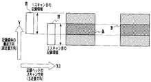
図1は、マルチパス記録方式を説明する図である。同図は、2回の主走査(以下、スキャンともいう)によって記録を完成させる、2パスのマルチパス記録を示しており、記録ヘッドHの位置と、記録媒体P上に記録される画像の記録領域との関係によってマルチパス記録を説明するものである。同図において、記録ヘッドHが主走査方向(矢印X1方向)に移動しつつ、記録データに基づいてインクを吐出することによって記録媒体P上に画像が記録され、また、このように記録ヘッドHが1回スキャンする毎に、記録ヘッドHにおける吐出口配列幅(以下、単に「記録ヘッドHの幅」ともいう)の1/2に相当する幅(以下、1/2バンド幅ともいう)ずつ記録媒体Pが副走査方向(矢印Y方向)に搬送される。なお、図1では、記録媒体Pの位置を固定し、その記録媒体Pに対して記録ヘッドHが副走査方向と反対の方向に移動するものとして表している。 FIG. 1 is a diagram for explaining a multi-pass recording method. The figure shows two-pass multi-pass printing in which printing is completed by two main scans (hereinafter also referred to as scans). The position of the print head H and the image recorded on the print medium P are shown. The multi-pass recording will be described based on the relationship with the recording area. In the figure, an image is recorded on the recording medium P by ejecting ink based on recording data while the recording head H moves in the main scanning direction (arrow X1 direction). Each time scanning is performed, a width (hereinafter also referred to as ½ band width) corresponding to ½ of the ejection opening array width in the recording head H (hereinafter also simply referred to as “width of the recording head H”). The recording medium P is conveyed in the sub-scanning direction (arrow Y direction). In FIG. 1, the position of the recording medium P is fixed, and the recording head H is shown as moving in the direction opposite to the sub-scanning direction with respect to the recording medium P.
このマルチパス記録では、1回目のスキャン(1スキャン目)で、記録ヘッドHの幅に相当する1バンド幅の画像データのうち、画素に関して例えば1/2の割合で間引かれた記録データに基づいて記録し、2回目のスキャンで、その1バンド幅の記録データのうち、上記の1回目のスキャンにおける間引きと相補的な間引きを行い、その記録データに基づいて記録する。従って、記録媒体P上における記録は、記録ヘッドHの2回のスキャンによって1/2バンド幅の記録領域ごとに完成してゆく。すなわち、記録媒体P上の1/2バンド幅分の記録領域についてみると、1回目のスキャンでは所定の間引かれた記録データに基づいて記録し、2回目のスキャンでは、1回目のスキャンにおける間引きと相補的な間引きによる記録データに基づいて記録する。なお、以下では、2パス記録の場合において、それぞれの領域について記録を完成させるための1回目のスキャンを1/2パス目、2回目のスキャンを2/2パス目といい、また、記録媒体P上の1/2バンド幅分の記録領域について、1/2パス目の記録のみが行われた領域を1/2パス記録領域、2/2パス目の記録も行われて画像が完成された領域を2/2パス記録領域という。 In this multi-pass printing, in the first scan (first scan), image data of one bandwidth corresponding to the width of the print head H is recorded on the print data thinned out at a rate of 1/2, for example, with respect to pixels. Based on the recording data, recording is performed on the basis of the recording data. The recording is performed based on the recording data. Accordingly, the recording on the recording medium P is completed for each recording area of ½ bandwidth by the scanning of the recording head H twice. That is, regarding the recording area corresponding to the ½ band width on the recording medium P, recording is performed based on the recording data thinned out in the first scan, and the second scan is performed in the first scan. Recording is performed based on recording data obtained by thinning and complementary thinning. In the following, in the case of two-pass printing, the first scan for completing the recording for each area is referred to as the ½ pass, the second scan is referred to as the 2/2 pass, and the recording medium For the recording area corresponding to the ½ band width on P, the area where only the ½ pass recording is performed is the ½ pass recording area and the 2/2 pass recording is also completed. This area is called a 2/2 pass recording area.
図2は、2パス記録を行った場合の、記録動作の途中において記録される画像を示す模式図である。記録動作の途中において、記録媒体の副走査方向後端の1/2バンド幅分の記録領域は1/2パス記録領域であり、1/2パス目の記録によって、間引かれた記録データに基づいた記録のみがなされている。そのため、その1/2パス記録領域は記録が未完成であり、その領域の濃度は、間引き率が例えば1/2の場合完成時の略1/2となる。 FIG. 2 is a schematic diagram showing an image recorded during the recording operation when two-pass recording is performed. During the recording operation, the recording area corresponding to the ½ band width at the rear end in the sub-scanning direction of the recording medium is a ½ pass recording area, and the recording data thinned out by the ½ pass recording is recorded. Only based records have been made. Therefore, the recording in the 1/2 pass recording area is not completed, and the density of the area is approximately 1/2 when the thinning rate is 1/2, for example.
以上の2パス記録方式に関する説明からも明らかなように、記録媒体上の同じ記録領域に対して、記録ヘッドを主走査方向に4回スキャンさせることによって画像の記録を完成させる4パス記録、記録媒体上の同じ記録領域に対して、記録ヘッドを主走査方向に8回スキャンさせることによって画像の記録を完成させる8パス記録等、基本的にいずれのパス数でも同様にマルチパス記録を実施することができる。 As is apparent from the above description of the two-pass recording method, four-pass recording and recording are performed to complete image recording by scanning the recording head four times in the main scanning direction with respect to the same recording area on the recording medium. Multi-pass printing is basically performed in the same manner for any number of passes, such as 8-pass printing in which the recording of the image is completed by scanning the recording head 8 times in the main scanning direction in the same recording area on the medium. be able to.
しかし、上述したマルチパス記録方式において、同じ記録領域に対する1回目のスキャンとその次の2回目のスキャンとの間の時間間隔(以下、記録時間差ともいう)が変化すると、その記録時間差に応じて記録濃度が変化し、記録画像において濃度ムラ(以下、時間差ムラともいう)が発生することがある。 However, in the above-described multi-pass recording method, if the time interval (hereinafter also referred to as a recording time difference) between the first scan and the next second scan for the same recording area changes, the recording time difference depends on the change. The recording density changes, and density unevenness (hereinafter also referred to as time difference unevenness) may occur in the recorded image.
図3および図4は、このような記録時間差に応じた濃度ムラ発生を説明する図である。 3 and 4 are diagrams for explaining the occurrence of density unevenness in accordance with such a recording time difference.
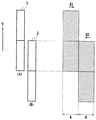
図3は、2パス記録における1/2パス目と2/2パス目との間の記録時間差が比較的短い場合における、記録媒体102に対するインクの浸透と定着の様子を模式的に表している。同図(a)に示すように、1/2パス目に吐出されたインク滴101aは、同図(b)に示すように、記録媒体102の表面に垂直な方向および表面に沿った方向に浸透してインク成分である染料などの色素が記録媒体102と物理的および化学的に結合する。そして、同図(c)に示す、2/2パス目に吐出されたインク滴101bは、同図(d)に示すように、記録媒体102の表面に垂直な方向および表面に沿った方向に浸透するものの、先に着弾したインク滴101aが定着している領域にはそれほど浸透、定着しない。これは、先に着弾したインク滴101aが未だ浸透しつつある状態にあることが考えられる。そのため、後から着弾したインク滴101bは、同図(d)に示すように、先に着弾したインク滴101aが浸透した領域のさらに下の方に浸透、定着することになる。なお、図3(c)、(d)に示す2パス目のインク滴101bの着弾位置もしくはその定着位置が、図(a)、(b)に示す1パス目のインク滴101aの着弾位置もしくは定着位置がずれているのは、マルチパス記録では各スキャンのインク吐出データが画素に関する間引き処理に基づいた相補的なものであることから、1パス目の2パス目に着弾する画素は同じでなく、例えば隣接しているからである。この点は、以下に示す図4でも同様である。
FIG. 3 schematically shows the state of ink permeation and fixing with respect to the
図4は、2パス記録方式における1/2パス目と2/2パス目との間の記録時間差が、上述した図に示した場合に較べて長い場合における、記録媒体102に対するインクの浸透と定着の様子を模式的に表している。同図(a)に示すように1/2パス目に吐出されたインク滴101aは、図3(a)に示した場合と同様、同図(b)に示すように記録媒体102の表面に垂直な方向および表面に沿った方向に浸透し、インク成分である染料などの色素が記録媒体102と物理的および化学的に結合する。そして、同図(c)に示す、2/2パス目に吐出されて後から着弾したインク滴101bは、図3(d)に示す場合と異なり、先に着弾した101aが浸透、定着している領域に比較的多く浸透する(図4(d))。これは、1/2パス目と2/2パス目との間の記録時間差が比較的長いことによって、先に着弾したインク滴101aが十分浸透して広がり、あるいはその揮発成分が蒸発することができるため、記録媒体102の単位体積当たりのインク滴101aの量が減少し、後から着弾したインク滴101bが浸透できるようになるものと考えられる。
FIG. 4 shows ink permeation into the
このように、1/2パス目と2/2パス目との記録時間差に応じて、記録媒体の表面付近に定着するインクの量、つまり染料などの色素の量が異なることがある。そして、記録濃度は記録媒体の表面付近に定着する色素が光を吸収する量に対応するため、1/2パス目と2/2パス目との記録時間差が異なると、それに応じて記録濃度が異なることになる。 As described above, the amount of ink fixed near the surface of the recording medium, that is, the amount of a pigment such as a dye may differ depending on the recording time difference between the 1/2 pass and the 2/2 pass. Since the recording density corresponds to the amount of light absorbed by the dye fixed near the surface of the recording medium, if the recording time difference between the 1/2 pass and the 2/2 pass is different, the recording density is accordingly changed. Will be different.
以上説明したように、マルチパス記録方式により画像を記録する場合、1/2パス目と2/2パス目との間の記録時間差が異なると、その前後の記録画像間で時間差ムラが生じることがある。 As described above, when an image is recorded by the multi-pass recording method, if the recording time difference between the 1/2 pass and the 2/2 pass is different, time difference unevenness occurs between the recorded images before and after that. There is.
図5は、双方向のマルチパス記録において、記録ヘッドが記録に際して走査する長さである記録画像幅(本明細書では、単に「記録幅」ともいう)と、1/2パス目と2/2パス目との記録時間差との関係について説明する図である。1スキャン目で記録ヘッドHを図中左から右方向へ走査して記録を行い、2スキャン目では右から左方向へ記録を行う場合、すなわち、いわゆる1、2スキャン目を双方向記録で行う場合の記録画像の左端の所定の大きさの領域Aと右端の同様の大きさの領域Bに着目する。左端の領域Aでは、記録ヘッドHが左から右方向へ走査して記録を行う初期の段階で1/2パス目の記録を行った後、記録ヘッドが右端で折り返して右から左方向への走査の最後の段階で2/2パス目を記録する。このため、1/2パス目を記録してから2/2パス目を記録するまでの記録時間差は比較的長くなる。一方、右端の領域Bでは、記録ヘッドが左から右方向へ走査して記録を行う最後の段階で1/2パス目の記録を行った後、記録ヘッドが右端で折り返して右から左方向への走査の初期の段階で2/2パス目を記録するので、1/2パス目を記録してから2/2パス目を記録するまでの記録時間差は比較的短くなる。そして、この領域Aのように記録ヘッドが折り返した後の走査の最後の段階で記録を行う領域では、記録時間差が記録幅に応じた時間となる。このため、記録幅の長短に応じて記録時間差が異なることになり、結果として、領域Aと領域Bとの濃度差は記録幅が長いほど大きくなる。 FIG. 5 shows a recording image width (which is also simply referred to as “recording width” in the present specification) that is a length that the recording head scans in recording in bidirectional multi-pass recording, a ½ pass, and 2 / It is a figure explaining the relationship with the recording time difference with the 2nd pass. In the first scan, recording is performed by scanning the recording head H from the left to the right in the drawing, and in the second scan, recording is performed from the right to the left, that is, so-called first and second scans are performed by bidirectional recording. In this case, attention is paid to a region A having a predetermined size at the left end of the recorded image and a region B having a similar size at the right end. In the leftmost area A, the recording head H scans from left to right and performs recording in the initial stage of recording, and then the recording head folds at the right end and turns from right to left. The 2 / 2nd pass is recorded at the last stage of scanning. For this reason, the recording time difference from the recording of the 1/2 pass to the recording of the 2/2 pass becomes relatively long. On the other hand, in the rightmost area B, the recording head scans from the left to the right and performs the recording in the last stage, and then the recording head turns back at the right end and moves from the right to the left. Since the 2/2 pass is recorded in the initial stage of the scanning, the recording time difference from the 1/2 pass to the 2/2 pass is relatively short. In the area where recording is performed at the last stage of scanning after the recording head is turned back as in the area A, the recording time difference is a time corresponding to the recording width. For this reason, the recording time difference varies depending on the length of the recording width, and as a result, the density difference between the region A and the region B increases as the recording width increases.
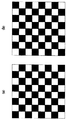
図6は、以上のように双方向マルチパス記録において走査における右端の領域と左端の領域で記録時間差が異なることによって、記録画像において生ずる濃度ムラ(時間差ムラ)を説明する図である。同図では、1/2パス目での記録から2/2パス目での記録までの記録時間差が長い領域をαで示し、短い領域をΒで示している。これからわかるように、双方向記録ではα領域とΒ領域が交互に生じ、これら領域間の濃度差は記録画像においてその両端それぞれで濃度の高低の繰り返しとして現れ、これが時間差ムラとして顕著に認識されることになる。 FIG. 6 is a diagram illustrating density unevenness (time difference unevenness) that occurs in a recorded image due to the difference in recording time between the rightmost region and the leftmost region in scanning in bidirectional multipass recording as described above. In the figure, an area where the recording time difference from recording in the 1/2 pass to recording in the 2/2 pass is long is indicated by α, and a short area is indicated by Β. As can be seen, in bidirectional recording, α regions and wrinkle regions occur alternately, and density differences between these regions appear as repeated high and low densities at both ends of the recorded image, which are remarkably recognized as time difference unevenness. It will be.
なお、上述の説明では2パスのマルチパス記録の場合について説明したが、3パス以上のマルチパス記録の場合も同様の時間差ムラが生じ得ることはもちろんである。この場合、例えば、m(3以上)パス記録において、(m−1)/mパス目の記録から記録が完成するm/mパス目の記録までの時間差だけでなく、記録が完成するまでの途中の記録におけるk/mパス目の記録から(k+1)/mパス目の記録までの連続する2つのスキャンによる時間差によっても、同様の時間差ムラを生じ得る。すなわち、(k+1)/mパス目でそれぞれ上記のα領域とΒ領域となる領域は、次の(k+2)/mパス目ではそれぞれ逆にB領域とα領域となるが、(k+1)/mパス目におけるインクの浸透、定着の具合によってその時点で上述した時間差ムラを生じており、この濃度ムラは最終的なその領域の時間差ムラに影響を与える。3パス以上のマルチパス記録の場合は、このような途中の時間差ムラの影響を含めてmパスによって記録が完成したときの最終的な時間差ムラが問題となる。 In the above description, the case of two-pass multi-pass printing has been described, but it is needless to say that the same time difference unevenness can occur in multi-pass printing of three or more passes. In this case, for example, in m (3 or more) pass recording, not only the time difference from the (m−1) / m pass recording to the m / m pass recording when the recording is completed, but also the recording completion. Similar time difference unevenness can also occur due to the time difference between two successive scans from the k / m-th pass recording to the (k + 1) / m-th pass recording in the middle of printing. That is, in the (k + 1) / m-th pass, the above-mentioned α region and Β region are respectively the B-region and α region in the next (k + 2) / m-pass, but (k + 1) / m The time difference unevenness described above is caused at that time due to the penetration and fixing of the ink in the pass, and this density unevenness affects the time difference unevenness in the final region. In the case of multi-pass printing of 3 passes or more, there is a problem of final time difference unevenness when recording is completed by m passes including the influence of such time difference unevenness.
以上説明した時間差ムラの問題は、特に、大判の記録媒体に記録を行う大判対応の記録装置において顕著となる。近年では従来のA4、A3サイズといった比較的小さなサイズの記録媒体に記録を行うインクジェット記録装置だけでなく、36inch幅、42inch幅、64inch幅、さらには72inch幅といった比較的大きなサイズの記録媒体に記録することができる、いわゆる大判インクジェット記録装置も発売されている。このような大判記録装置では、図5にて上述したように、上述したA領域とB領域の濃度差がその記録幅に応じたものであることから、両領域の濃度差はより大きくなり、結果として、時間差ムラの発生がより顕著となる。従って、比較的大きなサイズを記録できる大判インクジェット記録装置では時間差ムラは特に大きな問題となる。 The problem of time difference unevenness described above is particularly noticeable in a large format recording apparatus that records on a large format recording medium. In recent years, not only inkjet recording apparatuses that record on a relatively small recording medium such as A4 and A3 sizes, but also recording on a relatively large recording medium such as 36 inch width, 42 inch width, 64 inch width, and 72 inch width. A so-called large-format ink jet recording apparatus that can be used has also been put on the market. In such a large-format recording apparatus, as described above with reference to FIG. 5, the density difference between the A area and the B area described above is in accordance with the recording width. As a result, the occurrence of time difference unevenness becomes more prominent. Therefore, the time difference unevenness is a particularly serious problem in a large-format ink jet recording apparatus capable of recording a relatively large size.
以上のような記録時間差によって発生する時間差ムラを抑制する技術として、特許文献1に記載されたものが知られている。この文献によれば、記録領域を主走査方向において複数のエリアに分割し、それぞれのエリアに付与される黒インクおよびカラーインクのドット数をカウントし、黒、カラーが共にそれぞれの閾値を超えるエリアがある場合には、そのエリア数をカウントして、その数が所定数以上のときは、濃度むら(上述の時間差ムラに対応)が生じる可能性が高いとして、記録モードを双方向記録から片方向記録へ切り替えることが行われている。これによって記録画像の両端で発生する時間差ムラを抑制することを可能としている。また、同文献には、記録する画像データの幅、つまり、記録ヘッドが走査する範囲の幅を検知し、その幅が小さいときは時間差ムラの程度が小さいとして上記のエリア数が所定値以上でも、片方向記録に切り替えないようにすることも記載されている。
As a technique for suppressing the time difference unevenness caused by the recording time difference as described above, one described in
しかしながら、特許文献1に記載の時間差ムラを抑制する技術は、基本的に、インクドット数を求めその数が所定値以上のエリアについて時間差ムラが生じるか否かを判断し、それに応じて走査方向の切り替えを行うものである。このため、インクドット数をカウントする処理のための負荷やデータ量がそれだけ増し、また、処理のための時間が余分に必要となる。特に、大判インクジェット記録装置で記録する画像はその記録データ量が膨大であるため、その問題はより顕著になる。
However, the technique for suppressing the time difference unevenness described in
本発明は上記の問題を解消するためになされたものであり、その目的とするところは、比較的大きなサイズの画像を記録する大判インクジェット記録装置においても、双方向のマルチパス方式により記録を行う場合の記録時間差に起因して発生する時間差ムラを、処理負荷や処理のための時間の増大をそれほど伴わずに抑制することが可能なインクジェット記録装置を提供することにある。 The present invention has been made to solve the above-described problems, and the object of the present invention is to perform recording by a bidirectional multi-pass method even in a large-format inkjet recording apparatus that records a relatively large image. It is an object of the present invention to provide an ink jet recording apparatus capable of suppressing the time difference unevenness caused by the recording time difference without increasing the processing load and the time for processing so much.
上記目的を達成するために本発明は、インクを吐出するための複数の吐出口を備えた記録ヘッドを記録媒体に対して走査方向に往復走査させる走査手段と、前記記録媒体を前記走査方向とは異なる搬送方向に搬送させる搬送手段と、前記記録ヘッドの1回の走査で記録可能な領域の前記搬送方向における幅の1/N(Nは2以上の整数)の幅を有する領域内の記録が、前記記録ヘッドのN回の走査と、前記N回の走査に含まれる往走査と復走査の間に行われる前記1/Nの幅に相当する量の搬送とによって行われるように、前記走査手段、前記搬送手段および前記記録ヘッドを制御する制御手段と、 前記記録媒体の前記走査方向の幅に関連する情報を取得する取得手段と、前記取得手段が取得した情報に応じて、前記Nの値を可変に決定可能な決定手段と、を有し、前記決定手段は、前記取得手段により取得した情報が所定値未満の幅を示す場合には前記Nの値を第1の値に決定可能であり、前記取得手段が取得した情報が所定値以上の幅を示す場合には前記Nの値を前記第1の値よりも大きな第2の値に決定可能であることを特徴とする。 In order to achieve the above object, the present invention provides a scanning means for reciprocally scanning a recording head having a plurality of ejection openings for ejecting ink in the scanning direction with respect to the recording medium, and the recording medium in the scanning direction. Are transporting means for transporting in different transport directions, and recording in an area having a width of 1 / N (N is an integer of 2 or more) of the width in the transport direction of the area that can be recorded by one scan of the recording head. Is performed by N scans of the recording head and an amount of conveyance corresponding to the 1 / N width performed between the forward scan and the backward scan included in the N scans. scanning means, and control means for controlling said conveying means and said recording head, an acquisition unit configured to acquire information relating to the scanning width of the recording medium, according to information obtained by the obtaining unit, the N Variable value can be determined variably A determining means, wherein the determination unit, when the information acquired by the acquisition unit indicates a width of less than the predetermined value is determinable values of the N to a first value, said acquisition means When the acquired information shows a width equal to or greater than a predetermined value, the value of N can be determined as a second value larger than the first value .
なお、本発明の適用は、上述した大判のインクジェット記録装置に限られない。本発明は、特に記録幅の大きい大判記録装置において顕著な効果を生ずるが、通常のサイズの記録媒体に記録する装置においても、程度の差や装置の仕様に応じて上述した問題は生じ得るものであり、これに対し、上述した本発明による一定の作用、効果を生じ得るからである。このことは、以下の実施形態の説明からも明らかとなる。 The application of the present invention is not limited to the large-format ink jet recording apparatus described above. The present invention produces a remarkable effect particularly in a large-format recording apparatus having a large recording width. However, even in an apparatus for recording on a recording medium of a normal size, the above-described problems may occur depending on the degree of difference and the specifications of the apparatus. This is because, on the other hand, certain actions and effects of the present invention described above can be produced. This also becomes clear from the following description of the embodiment.
本発明によれば、記録媒体幅または記録幅が大きく、例えば記録媒体の右端および左端において濃度の高い走査領域(バンド)と濃度の低い走査領域(バンド)が副走査方向に交互に繰り返されるような濃度ムラ(バンドの走査方向の両端部での記録時間差が大きくなることに起因した時間差ムラ)が生じるようなときは、記録ヘッドの走査回数を増加させる処理を行っている。これにより、記録媒体の右端および左端において濃度の高い走査領域(バンド)と濃度の低い走査領域(バンド)が副走査方向に交互に繰り返されることにより発生する時間差ムラを目立たなくすることが可能となる。
According to the present invention, the recording medium width or the recording width is large. For example, a scanning area (band) having a high density and a scanning area (band) having a low density are alternately repeated in the sub-scanning direction at the right end and the left end of the recording medium. When there is a large density unevenness (time difference unevenness due to an increase in the recording time difference at both ends in the scanning direction of the band) , processing for increasing the number of scans of the recording head is performed. As a result, it is possible to make the time difference unevenness caused by the high-density scanning region (band) and the low-density scanning region (band) alternately repeated in the sub-scanning direction at the right and left ends of the recording medium inconspicuous. Become.
その結果、比較的大きなサイズの画像を記録する大判インクジェット記録装置においても、双方向のマルチパス方式により記録を行う場合の記録時間差に起因して発生する時間差ムラを、処理負荷や処理のための時間の増大をそれほど伴わずに抑制することが可能となる。 As a result, even in a large-format ink jet recording apparatus that records an image of a relatively large size, the time difference unevenness caused by the recording time difference in the case of recording by the bidirectional multi-pass method is reduced due to the processing load and processing. It is possible to suppress the increase without much time.
以下、図面を参照して本発明の実施形態を詳細に説明する。 Hereinafter, embodiments of the present invention will be described in detail with reference to the drawings.
図7は、本発明の一実施形態にかかる、最大記録幅64inchの大判インクジェット記録装置の内部構成を示す模式的斜視図である。 FIG. 7 is a schematic perspective view showing the internal configuration of a large-format inkjet recording apparatus having a maximum recording width of 64 inches according to an embodiment of the present invention.
図7において、キャリッジ1には記録ヘッド2が着脱自在に搭載される。キャリッジ1はガイド軸3に沿って移動可能なようにガイド軸3に支持されている。キャリッジ1にキャリッジベルト4の一部が固定され、一方、キャリッジベルト4は2つのモータプーリ5(一方は不図示)に張架されている。主走査モータ6の駆動によってキャリッジベルト4が回動することによりキャリッジ1はガイド軸3に沿って移動することができる。このキャリッジ1の移動によって記録ヘッド2を記録媒体7に対して走査することが可能となる。記録媒体7は、不図示の駆動モータによる搬送ローラ8の回転に伴って、副走査方向に搬送される。この搬送ローラの回転量を制御することにより、本実施形態のマルチパス記録における記録媒体7の搬送量を制御することができる。
In FIG. 7, a
キャリッジ1にはエンコーダセンサ9が設けられており、このエンコーダセンサ9がガイド軸3と並行に延在するリニアエンコーダスケール10上のスケールを検出することにより、キャリッジ1の位置や走査速度等を検出することができる。本実施形態では、光学式のエンコーダを採用しており、リニアエンコーダスケール10には、透明フィルム上に所定のピッチ間隔でスケールが設けられている。エンコーダセンサ9は、フォトインタラプタで構成され、上記所定ピッチ間隔に設けられたスケールを検出することで、このピッチに対応したエンコーダパルス信号を出力する。そして、このエンコーダパルス信号に基づいて記録ヘッドの走査位置を制御することにより、図10以降で後述されるように、記録幅に応じた走査範囲とすることができる。なお、エンコーダ9、10は光学式に限らず、磁気式などでもよいことはもちろんである。
The
図8は、記録ヘッド2が搭載された状態のキャリッジ1を模式的に示す図である。
FIG. 8 is a diagram schematically showing the
図8に示すように、記録ヘッド2は6個のヘッドチップ21〜26から構成されている。ヘッドチップ21はブラック(以下、Bkとも記す)のインク、22は淡シアン(以下、Pc)のインク、23はシアン(以下、C)のインク、24はマゼンタ(以下、M)のインク、25は淡マゼンタ(以下、Pm)のインク)、26はイエロー(以下、Y)のインクをそれぞれ吐出するものである。これらのヘッドチップはそれぞれ、例えば256個の吐出口を備え、記録データに基づいたヘッドドライバ(不図示)による駆動によってそれぞれの吐出口からインクを吐出する。この駆動は、それぞれの吐出口内のインク路に設けられた電気熱変換素子に記録データに応じた電気パルスを印加することによって行い、これにより、インクに気泡を生じさせその気泡の圧力によってインクを吐出することができるものである。
As shown in FIG. 8, the
キャリッジ1の主走査方向Xaに沿ってリニアエンコーダスケール10が配置されており、キャリッジ1にはリニアエンコーダスケール10のスケールを検出するためのエンコーダセンサ9が設けられている。また、キャリッジ1には、記録ヘッド2のキャリッジ1における主走査方向Xaの位置決めをするための位置決め部材31と、副走査方向Xbの位置決めをするための位置決め部材32とが設けられており、搭載に際して記録ヘッド2をこれら位置決め部材31、32にそれぞれ当接することにより、記録ヘッド2のそれぞれの方向の位置決めすることができる。キャリッジ1には、さらに記録媒体幅センサ33が取り付けられている。この記録媒体幅センサ33は記録媒体幅を検知するために用いられる。
A
図9は、図7に示したインクジェット記録装置における制御系の構成を示すブロック図である。 FIG. 9 is a block diagram showing a configuration of a control system in the ink jet recording apparatus shown in FIG.
図9において、200は本記録装置の主制御部をなすコントローラを示し、後述する図10などに示す処理などを実行するマイクロコンピュータ形態等のCPU201、そのシーケンスの実行手順に対応したプログラムやテーブル、ヒートパルスの電圧値、パルス幅、その他の固定データを格納するROM202、および記録データを展開する領域や作業用の領域等が設けられたRAM203を有する。33は図8に示した記録媒体の幅を検知するセンサを示し、この記録媒体幅センサからの出力値はコントローラ200に入力される。また、205は記録データの供給源をなすホスト装置を示し、このホスト装置205からの記録データ、その他コマンド、ステータス信号等は、インターフェース(I/F)206を介してコントローラ200およびバンドメモリ207との間にて送受信される。
In FIG. 9,
208はマスクパターンセレクタであり、CPU201に接続されて制御され、その出力はマルチパスデータ処理部209に入力される。207はバンドメモリであり、記録のための画像データがインターフェース206から転送され、CPU201の制御によって、所定の幅に分割された記録領域の記録に必要な画像データが1バンド分(各色インクについて記録ヘッドの1走査分)の記録データとして格納される。バンドメモリ207の出力は、マルチパスデータ処理部209に入力される。マルチパスデータ処理部209は、CPU201の制御によって、分割された記録領域の記録を複数回のスキャンで完了させるように画像データの間引き処理を実行し、1スキャン分の記録データを生成してヘッドドライバ210に出力する。ヘッドドライバ210は、記録や予備吐出の際に、記録データ等に応じて記録ヘッド2の電気熱変換素子(インク吐出用のヒータ)を駆動する。記録ヘッド2はヘッドドライバ210により制御され、キャリッジ1の移動に同期しながら、記録ヘッド2の吐出口からインクを吐出させることによって、1スキャン分の記録を実行することができる。6は、図1にて上述した、キャリッジ1を主走査方向に移動させるための駆動源となる主走査モータ、213は、そのドライバをそれぞれ示す。また、214は、記録用紙などの記録媒体を副走査方向に搬送するための駆動源となる副走査モータを示し、215は、そのドライバを示す。
A
(実施形態1)
図10は、本発明の第一の実施形態に係る記録動作の手順を示すフローチャートである。
(Embodiment 1)
FIG. 10 is a flowchart showing the procedure of the recording operation according to the first embodiment of the present invention.
図10において、先ず、ホスト装置205からインターフェース206を経由して記録指示コマンドと記録データが入力すると、CPU201はその1バンド分の記録データをバンドメモリ207に書き込む(ステップS501)。次に、マルチパスデータ処理部209は、バンドメモリ207から1バンド分の全ての画像データを読み出す(ステップS502)。
In FIG. 10, first, when a recording instruction command and recording data are input from the
次に、CPU201は、記録に用いる記録媒体の幅に関連する情報を取得する。そして、その取得した記録媒体の幅に関連する情報に応じてマルチパス記録におけるパス数を決定する(ステップS503)。詳細には、取得された記録媒体の幅に関連する情報によって図11にて後述されるテーブルを参照し、記録モードとして2パスまたは8パスのマルチパス記録モードを選択する。なお、記録媒体の幅に関連する情報は、記録媒体幅センサ33を用いて記録媒体の幅を検出することにより取得してもよく、また、センサによって検出するのではなく、例えば、ホスト装置から記録データとともに送られる記録媒体のサイズ情報に基づいて求めてもよい。
Next, the
本実施形態は、記録媒体の幅を求め、それが所定値以上のときは、それに応じて記録ヘッドの走査する範囲が広くなって記録時間差が長くなるため、マルチパスのパス数を増すことにより、発生する時間差ムラを目立たないようにする。 In this embodiment, the width of the recording medium is obtained, and when it is greater than or equal to a predetermined value, the scanning range of the recording head is widened accordingly and the recording time difference is increased. , Make the time difference unevenness unnoticeable.
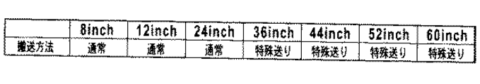
図11は、上記パス数の決定処理(ステップS503)で用いられる記録媒体幅とパス数の関係を示すテーブルである。本実施形態は、記録媒体の幅が比較的長い36inch以上で8パス記録とし、24inch以下の記録媒体幅が比較的短いときは2パス記録とする。なお、判断される記録媒体幅が上記テーブルに対応付けられた記録媒体幅でないときは、例えば、このテーブルの中で最も近い記録媒体幅に対応するパス数を決定する。 FIG. 11 is a table showing the relationship between the recording medium width and the number of passes used in the pass number determining process (step S503). In this embodiment, 8-pass recording is performed with a relatively long recording medium width of 36 inches or more, and 2-pass recording is performed when the recording medium width of 24 inches or less is relatively short. If the determined recording medium width is not the recording medium width associated with the table, for example, the number of passes corresponding to the closest recording medium width in the table is determined.
次に、ステップS504〜S506で、間引きによる記録データ生成、記録データを出力して行う記録動作、および記録媒体の搬送を行う。これらの処理は、以上のように決定されたパス数に応じたものとする。 Next, in steps S504 to S506, recording data is generated by thinning, a recording operation is performed by outputting the recording data, and the recording medium is transported. These processes correspond to the number of passes determined as described above.
先ず、ステップS504において、マルチパスデータ処理部209は、上記決定したパス数に応じた間引き処理を行う。例えば、2パス記録を行う場合の間引き処理は、バンドメモリ207から読み出した画像データを、図12(a)および(b)に示すマスクパターンを用いたマスク処理によって行う。2パス記録の1パス目について記録データを間引くためのマスクパターンとして、図12(a)に示す千鳥パターンを用いる。
First, in step S504, the multipath
なお、ステップS506の記録媒体搬送後に行う2パス目について記録データを間引くためのマスクパターンは、図12(b)に示す逆千鳥パターンを用いる。図13は、2パス記録の場合の、記録ヘッドと記録媒体の位置関係を示す図である。本実施形態の往復走査は、例えば、1回目のスキャンのときに記録ヘッド2が図13中のX1方向に往走査し、2回目のスキャンのときに記録ヘッド2が図13中のX2方向に復走査する。
Note that an inverted staggered pattern shown in FIG. 12B is used as a mask pattern for thinning out the recording data for the second pass after the recording medium is conveyed in step S506. FIG. 13 is a diagram showing the positional relationship between the recording head and the recording medium in the case of two-pass recording. In the reciprocating scan of this embodiment, for example, the
次に、ステップS505において、ステップS504で間引きにより生成された記録データをヘッドコントローラ210に出力するとともに、キャリッジ1を主走査方向にスキャンさせながら、記録ヘッド2からインクを吐出させて記録用紙上に画像などを記録する。すなわち、ステップS504において所定の間引きパターンによって生成された記録データに基づき、図13に示す段階Aのように記録ヘッド2がX1方向に往走査しつつ、記録ヘッド2からインクを吐出して1スキャン分の全領域に間引き画像を記録する。
Next, in step S505, the print data generated by the thinning out in step S504 is output to the
次に、ステップS506では、ステップS503で決定したパス数に応じた量の記録媒体搬送を行う。 例えば、2パスの場合、記録用紙を1/2バンド幅分だけ矢印Yの復走査方向に搬送する。図13に示すように、このステップS506における記録ヘッド2の位置は、1/2バンド幅分だけずれた位置Bになる。
Next, in step S506, the recording medium is conveyed in an amount corresponding to the number of passes determined in step S503. For example, in the case of two passes, the recording paper is conveyed in the backward scanning direction indicated by the arrow Y by a ½ bandwidth. As shown in FIG. 13, the position of the
そして、ステップS512で1ページ分の記録が終了していないと判断される間は、1回の走査ごとに、ホストから入力した1バンド分の記録データをバンドメモリ207に書き込み(ステップS507)、バンドメモリ207から1バンド分の全ての記録データを読み出す処理を行う(ステップS508)。そして、ステップS503で設定されているパス数に応じた間引き処理によって記録データを生成して記録動作を行うとともに、設定されたパス数に応じた記録媒体搬送を行う(ステップS509〜S511)。そして、記録用紙1枚分の記録が総て完了すると、本処理を終了する(ステップS512)。
While it is determined in step S512 that the recording for one page has not been completed, the recording data for one band input from the host is written in the
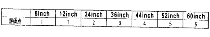
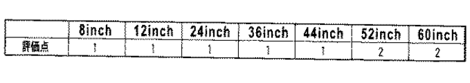
図14は、2パス記録および8パス記録それぞれにおける記録媒体幅と時間差ムラの発生状況との関係に応じた画像評価を示す図である。評価方法としては5段階の官能評価を用いており、それぞれの評価内容は次のとおりである。
5点:致命的な画像欠陥
4点:致命的ではないものの重大な欠点
3点:軽微な欠点
2点:画像欠陥がほとんど認められない
1点:画像欠陥が認められない
FIG. 14 is a diagram showing image evaluation according to the relationship between the recording medium width and the occurrence of time difference unevenness in 2-pass printing and 8-pass printing, respectively. As an evaluation method, five-step sensory evaluation is used, and the contents of each evaluation are as follows.
5 points:
図14に示すように、2パス記録では記録媒体幅が大きいほど時間差ムラが顕著となる一方、8パス記録では記録媒体幅が大きくなってもそれほど時間差ムラが目立たないことがわかる。 As shown in FIG. 14, the time difference unevenness becomes more conspicuous as the recording medium width becomes larger in the two-pass recording, whereas the time difference unevenness becomes less conspicuous even when the recording medium width becomes larger in the 8-pass recording.
以上の点から、図10にて上述した記録制御では、図11に示すテーブルを用いて記録媒体の幅に応じてパス数を選択する制御を行うものである。 From the above points, in the recording control described above with reference to FIG. 10, the number of passes is selected according to the width of the recording medium using the table shown in FIG.
図11に示すように、比較的短い記録媒体幅では、2パス記録においても時間差ムラが発生しないため、スループットの向上する2パス記録を選択する。比較的長い記録媒体幅の場合には、2パス記録を選択すると時間差ムラが顕著に発生する可能性があるため、8パス記録を選択することにより時間差ムラが目立つのを抑制することができる。 As shown in FIG. 11, when the recording medium width is relatively short, time difference unevenness does not occur even in two-pass printing, so two-pass printing with improved throughput is selected. In the case of a relatively long recording medium width, there is a possibility that the time difference unevenness will be remarkably generated when the 2-pass printing is selected. Therefore, the time difference unevenness can be suppressed by selecting the 8-pass recording.
すなわち、8パス記録では同一領域を複数回スキャンする回数が2パス記録の2回と比較して8回と4倍に増す。よって、図6に示す、αとBの領域それぞれの面積自体が小さくなるとともに、交互に繰り返す、繰り返し周波数が高くなる。その結果、時間差ムラを認識し難くなる。このように、同一の記録幅でも、パス数を増すほど時間差ムラを目立たなくすることができる。 That is, in the 8-pass printing, the number of times the same area is scanned a plurality of times is increased to 8 times and 4 times as compared with the 2-pass printing twice. Therefore, the area itself of each of the α and B regions shown in FIG. 6 becomes smaller, and the repetition frequency, which repeats alternately, becomes higher. As a result, it becomes difficult to recognize the time difference unevenness. Thus, even with the same recording width, the time difference unevenness can be made inconspicuous as the number of passes is increased.
なお、上記の例では、2パス記録と8パス記録の2通りから記録パス数を選択することとしたが、例えば6パスを加えて3通りから選択する、8パスと12パスの2通りから選択するといったように、記録パス数をどのように設定しても同様な効果が得られるのは以上の説明からも明らかである。 In the above example, the number of recording passes is selected from two ways of two-pass printing and eight-pass printing. For example, six passes are added and selected from three ways, from two ways of 8 passes and 12 passes. It is clear from the above description that the same effect can be obtained regardless of how the number of recording passes is set, such as selecting.
以上のとおり、本実施形態では、双方向のマルチパス記録において記録媒体幅に応じてパス数を選択することにより、双方向記録に起因して生じ得る時間差ムラを抑制することができる。 As described above, in this embodiment, by selecting the number of passes according to the recording medium width in bidirectional multi-pass recording, it is possible to suppress time difference unevenness that may occur due to bidirectional recording.
(実施形態2)
本実施形態は、双方記録における記録媒体の搬送を制御することにより走査領域の両端それぞれで記録時間差が異ならないようにし、時間差ムラを抑制するものである。
(Embodiment 2)
In this embodiment, by controlling the conveyance of the recording medium in both-side recording, the recording time difference is not different between both ends of the scanning area, and time difference unevenness is suppressed.
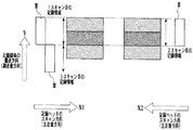
図15は、本発明の第2の実施形態に係る、2パス記録において搬送量を変更した場合(以下、特殊送りと表記する)の記録方法について説明する図であり、記録ヘッドHの位置と記録媒体P上に記録される画像の記録領域との関係を示している。 FIG. 15 is a diagram for explaining a recording method when the carry amount is changed (hereinafter referred to as special feed) in the two-pass recording according to the second embodiment of the present invention. The relationship with the recording area of the image recorded on the recording medium P is shown.
図15において、記録ヘッドHが主走査方向(矢印X1方向)に移動しつつ、記録データに基づいてインクを吐出することによって、1スキャン目の記録領域に対して画像などを記録する。本実施形態では、この往方向の走査の記録の後、復方向への走査の前に記録媒体の搬送は行わないよう制御する。そして、記録ヘッドHが、復方向である主走査方向(矢印X2方向)に移動しつつ、記録データに基づいてインクを吐出することによって、1スキャン目と同じ領域である2スキャン目の記録領域に記録を行う。そして、2スキャン目が終了すると、1バンド幅分記録媒体を副走査方向(矢印Y方向)に搬送する。このように、2N−1(Nは自然数)スキャン目終了時には記録媒体の搬送を行わず、同じ吐出口を用いて同じ領域の記録を行い、2Nスキャン目終了時に1バンド幅分の記録媒体搬送を行う。この場合、2N−1回目のスキャンでは、記録ヘッドHの吐出口列幅に相当する1バンド幅の記録データの内、画素について所定のパターンで間引かれた記録データに基づいて記録し、2N回目のスキャンでは、その1バンド幅の記録データの内、2N−1回目における間引きと相補的な間引きによる記録データに基づいて記録する。 In FIG. 15, the recording head H moves in the main scanning direction (arrow X1 direction) and ejects ink based on the recording data, thereby recording an image or the like on the recording area of the first scan. In the present embodiment, control is performed so that the recording medium is not conveyed after the recording in the forward scanning and before the scanning in the backward direction. The recording head H ejects ink based on the recording data while moving in the main scanning direction (the direction of the arrow X2) which is the backward direction, so that the recording area of the second scan, which is the same area as the first scan. To record. When the second scan is completed, the recording medium for one band width is conveyed in the sub-scanning direction (arrow Y direction). In this way, the recording medium is not transported at the end of the 2N-1 (N is a natural number) scan, but the same area is recorded using the same ejection port, and the recording medium is transported for one band width at the end of the 2N scan. I do. In this case, in the 2N-1th scan, recording is performed based on the recording data thinned out in a predetermined pattern with respect to the pixels in the recording data of one bandwidth corresponding to the ejection port array width of the recording head H. In the first scan, recording is performed based on the recording data by the thinning complementary to the thinning in the 2N-1th time out of the recording data of one bandwidth.
本実施形態の記録制御は、第1の実施形態に関して示した図10の処理における、ステップS503で、記録媒体幅を検出し、この検出した記録媒体幅に応じて、図18にて後述するテーブルを参照し、以上説明した特殊送りの記録モードを実行するか否かを決定する。そして、特殊送りをすると決定した場合は、ステップS506における記録媒体の搬送制御を、上述したように、2N−1(Nは自然数)スキャン目終了時には記録媒体の搬送を行わないようにする。なお、本実施形態の搬送制御において、通常の搬送と特殊送りの搬送との間の切り替えが行われる場合、ステップS504の記録データ生成は、切り替えに関して記録ヘッドの吐出口が対応する領域との関係で用いる吐出口を設定し、それに応じて記録データを対応付けることはもちろんである。 In the recording control of the present embodiment, the recording medium width is detected in step S503 in the process of FIG. 10 shown in the first embodiment, and a table described later in FIG. 18 according to the detected recording medium width. , Whether to execute the special feed recording mode described above is determined. If it is determined that special feeding is to be performed, the recording medium conveyance control in step S506 is not performed at the end of the 2N-1 (N is a natural number) scan as described above. In the transport control of the present embodiment, when switching between normal transport and special transport is performed, the print data generation in step S504 is related to the area corresponding to the discharge port of the print head with respect to the switch. Of course, the discharge ports used in the above are set, and the print data is associated with the discharge ports accordingly.
図16は、双方向2パス記録において特殊送りを行った場合の記録時間差およびそれによる濃度差を説明する図である。図6の場合と同様、1/2パス記録領域を記録してから2/2パス記録領域を記録するまでの記録時間差が長い場合にはαの表記、短い場合にはΒの表記で示している。図16に示すように、左端の領域はすべてα、右端の領域はすべてΒとなるため、左端と右端とを比較すると時間差ムラが発生するものの、左端および右端のいずれであっても副走査方向に隣接する領域では時間差ムラが発生しないため、濃淡領域が交互に繰り返される時間差ムラを大きく低減することができる。 FIG. 16 is a diagram for explaining the recording time difference and the resulting density difference when special feed is performed in bidirectional two-pass printing. As in the case of FIG. 6, when the recording time difference from the recording of the 1/2 pass recording area to the recording of the 2/2 pass recording area is long, α is indicated, and when it is short, it is indicated by Β. Yes. As shown in FIG. 16, since the left end region is all α and the right end region is all wrinkles, a time difference unevenness occurs when the left end and the right end are compared. Since the time difference unevenness does not occur in the region adjacent to the time region, the time difference unevenness in which the light and dark regions are alternately repeated can be greatly reduced.
図17は、特殊送りを行った場合の記録媒体幅と時間差ムラの発生状況との関係に応じた画像評価を示す図である。評価方法としては図14で用いた5段階の官能評価と同様である。上述したように特殊送りを行った場合にはそれぞれの端部における隣接した領域では記録時間差がほぼ等しくなるため、時間差ムラがほとんど発生していないが、記録媒体幅が大きい場合、わずかに評価が落ちる。 FIG. 17 is a diagram illustrating image evaluation in accordance with the relationship between the recording medium width and the occurrence of time difference unevenness when special feeding is performed. The evaluation method is the same as the five-step sensory evaluation used in FIG. As described above, when the special feed is performed, the recording time difference is almost equal in the adjacent areas at the respective end portions. Therefore, the time difference unevenness hardly occurs, but the evaluation is slightly evaluated when the recording medium width is large. drop down.
図18は、本実施形態に係る、搬送制御の決定処理で用いるテーブルを示す図である。 FIG. 18 is a diagram illustrating a table used in the conveyance control determination process according to the present embodiment.
同図に示すように、記録媒体幅が比較的小さい24inch以下では時間差ムラがそれほど顕著ではないため、通常の搬送を行う。一方、比較的記録媒体幅が大きい、36inch以上の場合は、時間差ムラが顕著に発生する可能性があるため、特殊送りを選択することにより、図17に示すように時間差ムラを抑制することができる。 As shown in the drawing, since the time difference unevenness is not so remarkable at a recording medium width of 24 inches or less, normal conveyance is performed. On the other hand, when the recording medium width is relatively large, that is, 36 inches or more, the time difference unevenness may occur remarkably. Therefore, by selecting the special feed, the time difference unevenness can be suppressed as shown in FIG. it can.
(実施形態3)
本実施形態は、記録媒体幅に応じて、記録ヘッドの走査速度、すなわち、記録時のキャリッジの移動速度を選択することにより、時間差ムラを抑制する。
(Embodiment 3)
In this embodiment, unevenness in time difference is suppressed by selecting the scanning speed of the recording head, that is, the moving speed of the carriage during recording, according to the recording medium width.
図19は、キャリッジの移動速度を変更した場合における記録媒体幅と時間差ムラの発生状況との関係に応じた画像評価を示す図である。評価方法としては図14で用いた5段階の官能評価と同様である。ここでは、25inch/secと50inch/secの2通りの場合について評価した。図19から明らかなように、いずれの記録媒体幅でも、キャリッジ速度が大きい、50inch/secの方が記録時間差が短くなるため、時間差ムラも抑制できる。 FIG. 19 is a diagram illustrating image evaluation according to the relationship between the recording medium width and the occurrence state of the time difference unevenness when the moving speed of the carriage is changed. The evaluation method is the same as the five-step sensory evaluation used in FIG. Here, two cases of 25 inch / sec and 50 inch / sec were evaluated. As can be seen from FIG. 19, since the recording time difference is shorter at 50 inch / sec, where the carriage speed is high, regardless of the recording medium width, unevenness in time difference can also be suppressed.
本実施形態の記録制御は、第1の実施形態に関して示した図10の処理における、ステップS503で、記録データに基づいて記録媒体幅を判断し、この判断した記録媒体幅に応じて、図20にて後述するテーブルを参照して、キャリッジ速度の異なる記録モードの1つを選択する。 In the recording control of the present embodiment, the recording medium width is determined based on the recording data in step S503 in the process of FIG. 10 shown in the first embodiment, and the recording medium width is determined according to the determined recording medium width. Referring to a table to be described later, one of the recording modes with different carriage speeds is selected.
図20は、そのキャリッジ移動速度を決定するために参照するテーブルを示す図である。同図に示すように、比較的短い記録媒体幅では、通常のキャリッジ速度である25inch/secでも時間差ムラが顕著に発生しない。そこで、記録媒体へのインク滴の着弾精度が比較的良好で、画像品位の高くなる場合が多い、25inch/secを選択する。一方、比較的長い記録媒体幅の場合には、より速いキャリッジ速度である、50inch/secを選択する。これにより、記録時間差を小さくし時間差ムラを抑制することが可能となる。50inch/secの場合には、記録媒体へのインク滴の着弾精度は若干劣化するものの、それによる画像品位の劣化は、時間差ムラによる画像品位の劣化と比較すると軽微なものであるため、総合的には画像品位が良化する。 FIG. 20 is a view showing a table referred to for determining the carriage moving speed. As shown in the figure, with a relatively short recording medium width, the time difference unevenness does not remarkably occur even at a normal carriage speed of 25 inches / sec. Therefore, 25 inch / sec is selected because the ink droplet landing accuracy on the recording medium is relatively good and the image quality is often high. On the other hand, in the case of a relatively long recording medium width, 50 inch / sec, which is a faster carriage speed, is selected. This makes it possible to reduce the recording time difference and suppress the time difference unevenness. In the case of 50 inches / sec, although the landing accuracy of the ink droplets on the recording medium is slightly deteriorated, the deterioration of the image quality due thereto is slight compared with the deterioration of the image quality due to the time difference unevenness. The image quality improves.
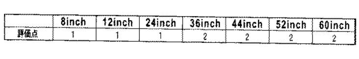
なお、上例では、キャリッジ速度を25inch/secと50inch/secの2通りから選択するとしたが、例えば、36inch/secを加えた3通りから選択しても、12.5inch/secと36inch/secの2通りから選択する、といったようにキャリッジ移動速度をどのように設定しても同様な効果が得られることは上記説明からも明らかである。 In the above example, the carriage speed is selected from two ways of 25 inch / sec and 50 inch / sec. However, for example, even if the carriage speed is selected from three ways including 36 inch / sec, 12.5 inch / sec and 36 inch / sec. It is also clear from the above description that the same effect can be obtained no matter how the carriage moving speed is set such as selecting from the above two.
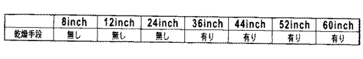
(実施形態4)
本実施形態は、記録媒体幅に応じて記録媒体を乾燥する処理(詳しくは、記録媒体上におけるインクの乾燥を促進させる処理)を行うか否かを決定し、これにより、時間差ムラを抑制するものである。
(Embodiment 4)
In the present embodiment, it is determined whether or not to perform a process of drying the recording medium (specifically, a process of promoting drying of ink on the recording medium) according to the width of the recording medium, thereby suppressing time difference unevenness. Is.
乾燥のための構成は公知の技術を用いることができ、記録媒体に対して接触し、あるいは非接触である構成のいずれでもよく、熱によって乾燥させる構成、気流によって乾燥させる構成、記録前に記録媒体を余熱する構成あるいは記録後に加熱する構成のいずれであってもよい。 A known technique can be used for the structure for drying, which may be a structure that is in contact with or not in contact with the recording medium, a structure that is dried by heat, a structure that is dried by an air current, and recording before recording. Either a configuration for preheating the medium or a configuration for heating after recording may be used.
図21は、記録媒体に乾燥処理を行った場合の、記録媒体幅と時間差ムラの発生状況との関係に応じた画像評価を示すである。評価方法としては図14で用いた5段階の官能評価と同様である。乾燥処理を追加することにより、記録時間差によらず常に記録媒体内でのインクの浸透、定着状態を一定に保つことが可能となるため、時間差ムラをかなり抑制できることがわかる。 FIG. 21 shows image evaluation according to the relationship between the width of the recording medium and the occurrence state of the time difference unevenness when the recording medium is dried. The evaluation method is the same as the five-step sensory evaluation used in FIG. It can be seen that by adding the drying process, it is possible to always maintain the permeation and fixing state of the ink in the recording medium regardless of the recording time difference, so that the time difference unevenness can be considerably suppressed.
本実施形態の記録制御は、第1の実施形態に関して示した図10の処理における、ステップS503で、記録データに基づいて記録媒体幅を判断し、この判断した記録媒体幅に応じて、図22にて後述するテーブルを参照して、乾燥処理の有無に応じた記録モードを選択する。 In the recording control of the present embodiment, the recording medium width is determined based on the recording data in step S503 in the process of FIG. 10 shown in the first embodiment, and the recording medium width is determined according to the determined recording medium width. The recording mode corresponding to the presence or absence of the drying process is selected with reference to a table to be described later.
図22は、そのテーブルを示す図である。同図に示すように、比較的短い記録媒体幅においては乾燥処理を行わないものとする。記録媒体幅が比較的短い場合は今まで述べてきたように時間差ムラの程度が画像品位に及ぼす影響が少ないため、乾燥処理を行わないようにし、これにより、記録制御を単純化し、また、電力消費を抑えることができる。一方、記録媒体幅が比較的長い場合には、乾燥処理を行う。これにより、インクの浸透、定着を促進し、結果として、走査領域の両端で記録時間差に応じた浸透などの違いから生じる濃度差を少なくし、これにより、時間差ムラを抑制することが可能となる。 FIG. 22 is a diagram showing the table. As shown in the figure, it is assumed that the drying process is not performed for a relatively short recording medium width. If the width of the recording medium is relatively short, as described above, the degree of time difference unevenness has little effect on the image quality, so that the drying process is not performed, thereby simplifying the recording control and reducing power consumption. Consumption can be suppressed. On the other hand, when the recording medium width is relatively long, a drying process is performed. As a result, ink penetration and fixing are promoted, and as a result, density differences resulting from differences such as penetration according to the recording time difference at both ends of the scanning region are reduced, thereby making it possible to suppress time difference unevenness. .
(実施形態5)
以上説明した例は、いずれも記録媒体の幅を検出しそれに応じて記録制御を切り替えることにより、時間差ムラが目立たないようにするものである。しかし、本発明の適用はこのような形態に限られない。以上説明した実施形態1〜4のそれぞれで記録媒体の幅の代わりに、実際の記録幅を検出するようにしてもよい。この記録幅は記録ヘッドの走査範囲に関わるものであり、走査領域における記録時間差を定める要因となる。
(Embodiment 5)
In each of the examples described above, the time difference unevenness is made inconspicuous by detecting the width of the recording medium and switching the recording control accordingly. However, the application of the present invention is not limited to such a form. In each of the first to fourth embodiments described above, the actual recording width may be detected instead of the width of the recording medium. This recording width relates to the scanning range of the recording head, and is a factor that determines the recording time difference in the scanning area.
記録幅は、記録媒体上に記録される画像の走査方向における幅であり、本実施形態では、1ページのデータにおける最大幅を記録幅とする。あるいは、1ページの先頭行の長さを記録幅とすることもできる。そして、記録ヘッドの走査を、この記録幅に応じた範囲で走査するよう制御する。例えば、記録幅が記録媒体の幅より小さいときは、記録ヘッドは記録媒体の幅全部にわたって走査するのではなく、それより小さい、記録データに基づいて画像などを記録するのに必要な範囲である記録幅の範囲内で走査する。 The recording width is the width in the scanning direction of the image recorded on the recording medium. In the present embodiment, the maximum width in one page of data is the recording width. Alternatively, the length of the first line of one page can be used as the recording width. Then, the recording head is controlled to scan within a range corresponding to the recording width. For example, when the recording width is smaller than the width of the recording medium, the recording head does not scan the entire width of the recording medium, but is smaller than that required for recording an image or the like based on the recording data. Scan within the recording width.
すなわち、記録ヘッドが走査する範囲は記録幅に対応しそれが比較的大きいときはそれに応じて長くなるため、往復走査による時間差ムラもそれに応じて顕著になる。このため、本実施形態では、記録幅に関連する情報を取得し、それが所定値以上のときは、実施形態1〜4で説明した記録制御のいずれかをすることにより、発生する時間差ムラを目立たないようにすることもできる。 That is, the range scanned by the recording head corresponds to the recording width and becomes longer when the recording head is relatively large. Therefore, the time difference unevenness due to the reciprocating scanning becomes significant accordingly. For this reason, in the present embodiment, information related to the recording width is acquired, and when the information is equal to or greater than a predetermined value, any of the recording control described in the first to fourth embodiments is performed, so that the generated time difference unevenness is reduced. It can also be made inconspicuous.
(実施形態6)
本実施形態は、上述した実施形態5と同様に記録幅に応じて記録制御を切り替える形態であり、実施形態5と異なる点は、1バンド幅分の記録データごとに、記録幅の判断を行い、また、その判断された記録幅に応じた記録モードの切り替えを行うものである。そして、記録制御は、具体的には、実施形態1と同様にパス数の切り替えである。
(Embodiment 6)
This embodiment is a mode in which the recording control is switched according to the recording width as in the fifth embodiment described above. The difference from the fifth embodiment is that the recording width is determined for each recording data of one band width. In addition, the recording mode is switched according to the determined recording width. The recording control is specifically switching of the number of passes as in the first embodiment.
図23は、本実施形態に係る記録動作の手順を示すフローチャートである。 FIG. 23 is a flowchart showing the procedure of the recording operation according to the present embodiment.
図23において、先ず、ホスト装置205からインタフェース206を経由して記録指示コマンドと記録データが入力すると、CPU201はその1バンド分の記録データをバンドメモリ207に書き込む(ステップS401)。次に、マルチパスデータ処理部209は、バンドメモリ207から1バンド分の全ての画像データを読み出す(ステップS402)。
In FIG. 23, first, when a recording instruction command and recording data are input from the
そして、CPU201は、読み出した記録データに基づいて、その記録幅を判定して、それに応じてマルチパス記録におけるパス数を決定する(ステップS403)。詳細には、判定された記録幅によって図24にて後述されるテーブルを参照し2パスまたは8パスのマルチパス記録を行う。そのために、先ず、このパス数を決定するための基準となる記録幅を求める。記録幅は、記録媒体上に記録される画像の走査方向における幅であり、本実施形態では、上記の読み出される1バンド分のデータが表す画像の最大幅を記録幅としている。そして、記録ヘッドの走査を、この記録幅に応じた範囲で走査するよう制御する。例えば、記録幅が記録媒体の幅より小さいときは、記録ヘッドは記録媒体の幅全部にわたって走査するのではなく、それより小さい、記録データに基づいて画像などを記録するのに必要な範囲である記録幅の範囲内で走査する。
Then, the
図24は、上記パス数の決定処理(ステップS403)で用いられる記録幅とパス数の関係を示すテーブルである。本実施形態は、比較的記録幅が長い36inch以上で8パス記録とし、24inch以下の記録幅が比較的短いときは2パス記録とする。 FIG. 24 is a table showing the relationship between the recording width and the number of passes used in the pass number determination process (step S403). In this embodiment, 8-pass recording is performed with a relatively long recording width of 36 inches or more, and 2-pass recording is performed when the recording width of 24 inches or less is relatively short.
このパス数決定処理(ステップS403)では、以上説明したパス数決定処理に加え、この決定で、パス数の変更があるときは、次のステップS404およびそれ以降の処理に加え、あるいはこれらの処理とともに、パス数切り替え処理を行う。この切り替え処理は、例えば、特開平07−237321号公報に記載された方法で行うことができる。例えば、2パスを8パスに切り替える場合、2パスに対応した1/2バンド幅分の記録媒体を搬送をした後、記録媒体の搬送を行わずに8回の走査をするとともに記録ヘッドのインク吐出に用いる吐出口を1/8バンド幅分づつ増して行くことにより、切り替えを行う。8パスから2パスに切り替える場合は、1/8バンド幅分の搬送は行わずに、8回の走査をするとともに上記と同様インク吐出に用いる吐出口を1/8バンド幅分づつ増して行って、2パス目で完成すべき残された記録領域を完成する。 In this pass number determination process (step S403), in addition to the above-described pass number determination process, if there is a change in the number of paths in this determination, in addition to the next step S404 and subsequent processes, or these processes At the same time, the path number switching process is performed. This switching process can be performed, for example, by the method described in Japanese Patent Application Laid-Open No. 07-237321. For example, when switching from 2 passes to 8 passes, after the recording medium of 1/2 bandwidth corresponding to 2 passes is transported, 8 scans are performed without transporting the recording medium, and the ink of the recording head Switching is performed by increasing the number of ejection ports used for ejection by 1/8 bandwidth. In the case of switching from 8 passes to 2 passes, 8 times of scanning is performed without carrying the 1/8 bandwidth, and the number of ejection ports used for ink ejection is increased by 1/8 bandwidth as described above. Thus, the remaining recording area to be completed in the second pass is completed.
次に、ステップS404〜S406で、間引きによる記録データ生成、記録データを出力して行う記録動作、および記録媒体の搬送を行う。これらの処理は、以上のようなパス数切り替え処理が行われる場合は、それぞれ切り替え処理に応じたものとする。 Next, in steps S404 to S406, recording data generation by thinning, recording operation performed by outputting the recording data, and conveyance of the recording medium are performed. These processes correspond to the switching process when the above-described path number switching process is performed.
先ず、ステップS404において、マルチパスデータ処理部209は、上記決定したパス数に応じた間引き処理を行う。例えば、2パス記録を行う場合の間引き処理は、バンドメモリ207から読み出した画像データを、図12(a)および(b)に示したマスクパターンを用いたマスク処理によって行う。2パス記録の1パス目について記録データを間引くためのマスクパターンとして、図12(a)に示す千鳥パターンを用いる。ステップS406の記録媒体搬送後に行う2パス目について記録データを間引くためのマスクパターンは、図12(b)に示す逆千鳥パターンを用いる。本実施形態の往復走査は、例えば、1回目のスキャンのときに記録ヘッド2が、図13に示したX1方向に往走査し、2回目のスキャンのときに記録ヘッド2がX2方向に復走査する。次に、ステップS405で、ステップS404で間引きにより生成された記録データをヘッドコントローラ210に出力するとともに、キャリッジ1を主走査方向にスキャンさせながら、記録ヘッド2からインクを吐出させて記録用紙上に画像などを記録する。すなわち、ステップS404において千鳥パターンによって生成された記録データに基づき、図13に示す段階Aのように記録ヘッド2がX1方向に往走査しつつ、記録ヘッド2からインクを吐出して1スキャン分の全領域に間引き画像を記録する。さらに、ステップS406では、ステップS403で決定したパス数に応じた量の記録媒体搬送を行う。例えば、2パスの場合、記録用紙を1/2バンド幅分だけ矢印Yの復走査方向に搬送する。図13に示すように、このステップS406における記録ヘッド2の位置は、1/2バンド幅分だけずれた位置Bになる。
First, in step S404, the multipath
ステップS407では、ステップS402で読み出した1バンド分のデータと同じデータを再度読み出し、次のステップS408で、例えば、2パス記録の場合、図12(b)に示す逆千鳥マスクパターンを用いた間引き処理によって記録データを生成し、ステップS409で図13に示す2パス目の記録を行う。 In step S407, the same data as the data for one band read in step S402 is read again, and in the next step S408, for example, in the case of 2-pass printing, thinning using the reverse staggered mask pattern shown in FIG. Recording data is generated by the processing, and the second pass recording shown in FIG. 13 is performed in step S409.
そして、ステップS410では、ステップS401でホスト装置から送られた記録データの書き込みを行ってから、ステップS406の処理による搬送量の累計が1バンド幅分に達したか否かを判断する。すなわち、記録媒体の搬送によって記録ヘッドが対応する領域が、ホストから未だ記録データが送られていないデータを記録する領域のものとなると、ホスト装置から送られた記録データの書き込みをするため、(ステップS411の判断を介して)Sステップ401に戻る。そして、本実施形態では、この新たなデータの書き込みごとにそのデータに基づいて記録幅を判断し、その判断に応じてパス数を決定する(ステップS402、S403)。 In step S410, after the recording data sent from the host device in step S401 is written, it is determined whether or not the total transport amount by the processing in step S406 has reached one bandwidth. That is, when the area corresponding to the recording head by the conveyance of the recording medium is an area for recording data to which recording data has not yet been sent from the host, the recording data sent from the host device is written ( Return to step S401 (via step S411). In this embodiment, each time this new data is written, the recording width is determined based on the data, and the number of passes is determined according to the determination (steps S402 and S403).
ステップS410で、1バンド分の搬送が行われていないと判断したときは、ステップS406〜S409の処理を繰り返す。そして、記録用紙1枚分の記録が総て完了すると、本処理を終了する(ステップS411)。 If it is determined in step S410 that one band has not been transported, the processes in steps S406 to S409 are repeated. Then, when all the recording for one sheet of recording paper is completed, the present process is terminated (step S411).
図25は、2パス記録の場合における記録幅とそれに応じた記録時間差との関係を示す図であり、図6に示した記録領域の左端における記録時間差を、記録幅別に表記している。図6の場合と同様の符号を用いて、1/2パス記録領域を記録してから2/2パス記録領域を記録するまでの記録時間差が長い方についてαで表し、短い方についてΒで表している。図25から明らかなように、副走査方向に交互に存在するαの領域とΒの領域の時間差の差分が記録幅が大きくなるほど大きくなることがわかる。この差分は、交互に現れる領域の濃度差に対応し、従って、記録幅が大きくなるほど時間差ムラが大きくなることがわかる。 FIG. 25 is a diagram showing the relationship between the recording width and the recording time difference corresponding to the two-pass recording. The recording time difference at the left end of the recording area shown in FIG. 6 is shown for each recording width. Using the same reference numerals as in FIG. 6, α indicates the longer recording time difference from recording the 1/2 pass recording area to recording the 2/2 pass recording area, and vice versa. ing. As is apparent from FIG. 25, it can be seen that the difference in the time difference between the α region and the wrinkle region alternately present in the sub-scanning direction increases as the recording width increases. This difference corresponds to the density difference between the alternately appearing regions. Therefore, it can be seen that the time difference unevenness increases as the recording width increases.
図26はこのことを示す図であり、2パス記録における記録幅と時間差ムラの発生状況との関係に応じた画像評価を示す図である。評価方法としては図14に示したものと同じである。 FIG. 26 is a diagram illustrating this, and is a diagram illustrating image evaluation according to the relationship between the recording width and the occurrence of time difference unevenness in two-pass recording. The evaluation method is the same as that shown in FIG.
図27は、図25、図26に示したものと同じ記録幅による記録を8パス記録としたときの、記録幅と時間差ムラの発生状況との関係に応じた画像評価を示す図である。評価方法としては図14で示した5段階の官能評価と同様である。 FIG. 27 is a diagram showing image evaluation in accordance with the relationship between the recording width and the occurrence state of the time difference unevenness when the recording with the same recording width as that shown in FIGS. The evaluation method is the same as the five-step sensory evaluation shown in FIG.
8パス記録では同一領域を複数回スキャンする回数が2パス記録の2回と比較して8回と4倍に増す。これにより、αとBの領域それぞれの面積自体が小さくなるとともに、交互に繰り返す、繰り返し周波数が高くなり、結果として、時間差ムラが認識し難くなる。このように、同一の記録幅でも、パス数を増すほど時間差ムラを目立たなくすることができる。 In 8-pass printing, the number of times that the same area is scanned a plurality of times is increased to 4 times, 8 times, compared to twice in 2-pass printing. As a result, the area of each of the α and B regions itself decreases, and the repetition frequency that repeats alternately increases, resulting in difficulty in recognizing time difference unevenness. Thus, even with the same recording width, the time difference unevenness can be made inconspicuous as the number of passes is increased.
以上の点から、図23にて上述した記録制御では、図24に示すテーブルを用いて記録幅に応じてパス数を切り替える制御を行うものである。 From the above points, in the recording control described above with reference to FIG. 23, the number of passes is controlled according to the recording width using the table shown in FIG.
図24に示すように、比較的短い記録幅では、2パス記録においても時間差ムラが発生しないため、スループットの向上する2パス記録を選択する。比較的長い記録幅の場合には、2パス記録を選択すると時間差ムラが顕著に発生する可能性があるため、8パス記録を選択することにより時間差ムラを抑制する。 As shown in FIG. 24, in the case of a relatively short recording width, time difference unevenness does not occur even in 2-pass recording, so 2-pass recording that improves throughput is selected. In the case of a relatively long recording width, there is a possibility that the time difference unevenness may occur remarkably when the 2-pass printing is selected. Therefore, the time difference unevenness is suppressed by selecting the 8-pass recording.
以上のとおり、本実施形態では、双方向のマルチパス記録において1バンドデータごとの記録幅に応じてパス数を選択することにより、双方向記録に起因して生じ得る時間差ムラをより高い精度で抑制することができる。 As described above, in this embodiment, by selecting the number of passes according to the recording width for each band data in bidirectional multi-pass recording, the time difference unevenness that can be caused by bidirectional recording can be achieved with higher accuracy. Can be suppressed.
(実施形態7)
本実施形態は、以上説明した記録媒体幅に応じて、走査方向の切り替えを行うものである。すなわち、記録媒体幅が大きい場合は、双方向記録を片方向記録に切り替えて時間差ムラを抑制する。
(Embodiment 7)
In the present embodiment, the scanning direction is switched in accordance with the recording medium width described above. That is, when the recording medium width is large, the bidirectional recording is switched to the unidirectional recording to suppress the time difference unevenness.
具体的には、図10に示した記録制御のそれぞれステップS503またはステップS403の処理で、記録媒体幅を検出し、それに応じて双方向記録モードまたは片方向記録モードを選択する。 Specifically, the recording medium width is detected by the processing of step S503 or step S403 of the recording control shown in FIG. 10, and the bidirectional recording mode or the unidirectional recording mode is selected accordingly.
図28は、2パス記録の場合の片方向記録における記録時間差について説明する図である。1スキャン目で左から右方向へ記録を行った後、復方向の右から左方向では記録を行わずにキャリッジの移動のみを行い、2スキャン目も左から右方向へ記録を行う。この場合の記録画像の左端の領域Aと右端の領域Bのうち、領域Aでは、記録ヘッドが左から右方向へ記録を行う初期の段階で1/2パス目の記録を行った後、記録ヘッドが左から右方向へ記録を続け、更に記録ヘッドが右端で折り返して右から左方向へ記録は行わずにキャリッジの移動のみが行われ、1/2パス目と同様に左から右方向へ記録を行う初期の段階で2/2パス目を記録する。この結果、1/2パス目を記録してから2/2パス目を記録するまでの記録時間差は比較的長くなる。右端の領域Bでも同様であり、1/2パス目を記録してから2/2パス目を記録するまでの記録時間差は長くなる。 FIG. 28 is a diagram for explaining a recording time difference in one-way recording in the case of two-pass recording. After recording from the left to the right in the first scan, only the carriage is moved without recording from the right to the left in the backward direction, and recording is also performed from the left to the right in the second scan. Of the left end area A and right end area B of the recorded image in this case, in area A, the recording head performs recording in the initial stage of recording from left to right, and then performs recording after the 1/2 pass. The head continues to record from left to right, and the recording head folds back at the right end so that only the carriage is moved without recording from right to left, and from left to right as in the 1/2 pass. The 2 / 2nd pass is recorded at the initial stage of recording. As a result, the recording time difference from recording the 1/2 pass to recording the 2/2 pass becomes relatively long. The same applies to the rightmost region B, and the recording time difference from when the 1/2 pass is recorded to when the 2/2 pass is recorded becomes longer.
図29は、上記2パスの片方向記録における記録時間差が、記録画像の両端においてどうのように現れるかを示す図である。上述した各実施形態と同様、1/2パス目を記録してから2/2パス目を記録するまでの記録時間差が長い場合にはαの表記、短い場合にはΒの表記で示す場合、図29に示す場合は、図28で説明したように両端A、Bで時間差が同じであるため、領域αのみが発生する。従って、画像両端それぞれにおいて濃、淡が繰り返される時間差ムラは発生しない。 FIG. 29 is a diagram illustrating how the recording time difference in the two-pass unidirectional recording appears at both ends of the recorded image. As in the above-described embodiments, when the recording time difference from the recording of the 1/2 pass to the recording of the 2/2 pass is long, α is indicated, and when the recording time difference is short, it is indicated by Β. In the case shown in FIG. 29, since the time difference is the same at both ends A and B as described in FIG. 28, only the region α occurs. Accordingly, there is no time difference unevenness in which dark and light are repeated at both ends of the image.
図30は、片方向記録を行った場合の記録媒体幅と時間差ムラの発生状況との関係における画像評価を示す図である。評価方法としては図14で用いた5段階の官能評価と同様である。前述したように片方向記録では記録時間差がほぼ等しくなり、時間差ムラがほとんど発生していない。 FIG. 30 is a diagram illustrating image evaluation in the relationship between the recording medium width and the occurrence of time difference unevenness when unidirectional recording is performed. The evaluation method is the same as the five-step sensory evaluation used in FIG. As described above, the recording time difference is almost equal in the one-way recording, and the time difference unevenness hardly occurs.
図30は、片方向記録か双方向記録を選択する処理で参照するテーブルを示す図である。同図に示すように、比較的短い記録媒体幅の場合は、双方向記録を選択する。一方、比較的長い記録媒体幅の場合には、双方向記録を選択してしまうと時間差ムラが顕著に発生するため、片方向記録を選択することにより、時間差ムラを抑制する。 FIG. 30 is a diagram illustrating a table referred to in the process of selecting one-way recording or two-way recording. As shown in the figure, in the case of a relatively short recording medium width, bidirectional recording is selected. On the other hand, in the case of a relatively long recording medium width, if the bidirectional recording is selected, the time difference unevenness occurs remarkably. Therefore, the time difference unevenness is suppressed by selecting the unidirectional recording.
(他の実施の形態)
上記の実施形態6は検出する記録幅に応じた記録制御がマルチパス記録のパス数を切り替えるものであるが、実施形態6の記録制御として、実施形態2〜4で説明した記録制御のいずれかを適用してもよい。
(Other embodiments)
In the sixth embodiment, the recording control corresponding to the detected recording width switches the number of passes of multi-pass printing. As the recording control in the sixth embodiment, one of the recording controls described in the second to fourth embodiments. May be applied.
また、上述した各実施形態は、イエロー、マゼンタ、シアン、淡マゼンタ、淡シアン、およびブラックのインクを用いて記録する場合について説明したが、用いるインクの組合せはこれに限られず、本発明の適用が、用いるインクの組合せによらないことは以上の説明からも明らかである。 In each of the above-described embodiments, the case where printing is performed using yellow, magenta, cyan, light magenta, light cyan, and black inks has been described. However, the combination of inks to be used is not limited thereto, and the application of the present invention is not limited thereto. However, it is clear from the above description that it does not depend on the combination of inks used.
1 キャリッジ
2 記録ヘッド
3 キャリッジガイド軸
4 キャリッジベルト
5 モータプーリ
6 主走査モータ
7 記録媒体
8 搬送ローラ
9 エンコーダセンサ
10 リニアエンコーダスケール
21 Bkチップ
22 Pcチップ
23 Cチップ
24 Mチップ
25 Pmチップ
26 Yチップ
33 記録媒体幅センサ
200 コントローラ
201 CPU
202 ROM
203 RAM
205 ホスト装置
206 I/F(インターフェース)
207 バンドメモリ
208 マスクパターンセレクタ
209 マルチパスデータ処理部
210 ヘッドドライバ(コントローラ)
213 主走査モータドライバ
214 副走査モータ
215 副走査モータドライバ
DESCRIPTION OF
202 ROM
203 RAM
205 Host device 206 I / F (interface)
207
213 Main
Claims (1)
前記記録媒体を前記走査方向とは異なる搬送方向に搬送させる搬送手段と、
前記記録ヘッドの1回の走査で記録可能な領域の前記搬送方向における幅の1/N(Nは2以上の整数)の幅を有する領域内の記録が、前記記録ヘッドのN回の走査と、前記N回の走査に含まれる往走査と復走査の間に行われる前記1/Nの幅に相当する量の搬送とによって行われるように、前記走査手段、前記搬送手段および前記記録ヘッドを制御する制御手段と、
前記記録媒体の前記走査方向の幅に関連する情報を取得する取得手段と、
前記取得手段が取得した情報に応じて、前記Nの値を可変に決定可能な決定手段と、を有し、
前記決定手段は、前記取得手段により取得した情報が所定値未満の幅を示す場合には前記Nの値を第1の値に決定可能であり、前記取得手段が取得した情報が所定値以上の幅を示す場合には前記Nの値を前記第1の値よりも大きな第2の値に決定可能であることを特徴とするインクジェット記録装置。 Scanning means for reciprocally scanning a recording medium having a plurality of ejection openings for ejecting ink in a scanning direction with respect to a recording medium ;
Conveying means for conveying the recording medium in a conveying direction different from the scanning direction ;
Recording in an area having a width of 1 / N (N is an integer of 2 or more) in the transport direction of an area that can be recorded by one scanning of the recording head is N times of scanning of the recording head. The scanning unit, the transport unit, and the recording head are performed by the transport corresponding to the 1 / N width performed between the forward scan and the backward scan included in the N scans. Control means for controlling;
Obtaining means for obtaining information relating to the scanning width of the recording medium,
Determining means capable of variably determining the value of N according to the information acquired by the acquiring means;
The determining means can determine the value of N as a first value when the information acquired by the acquiring means is less than a predetermined value, and the information acquired by the acquiring means is greater than or equal to a predetermined value. In the case of indicating a width, the value of N can be determined as a second value larger than the first value .
Priority Applications (2)
| Application Number | Priority Date | Filing Date | Title |
|---|---|---|---|
| JP2003385747A JP4387768B2 (en) | 2003-11-14 | 2003-11-14 | Inkjet recording device |
| US10/985,966 US7396100B2 (en) | 2003-11-14 | 2004-11-12 | Ink jet printing apparatus and ink jet printing method |
Applications Claiming Priority (1)
| Application Number | Priority Date | Filing Date | Title |
|---|---|---|---|
| JP2003385747A JP4387768B2 (en) | 2003-11-14 | 2003-11-14 | Inkjet recording device |
Publications (3)
| Publication Number | Publication Date |
|---|---|
| JP2005144868A JP2005144868A (en) | 2005-06-09 |
| JP2005144868A5 JP2005144868A5 (en) | 2006-08-03 |
| JP4387768B2 true JP4387768B2 (en) | 2009-12-24 |
Family
ID=34567386
Family Applications (1)
| Application Number | Title | Priority Date | Filing Date |
|---|---|---|---|
| JP2003385747A Expired - Fee Related JP4387768B2 (en) | 2003-11-14 | 2003-11-14 | Inkjet recording device |
Country Status (2)
| Country | Link |
|---|---|
| US (1) | US7396100B2 (en) |
| JP (1) | JP4387768B2 (en) |
Families Citing this family (13)
| Publication number | Priority date | Publication date | Assignee | Title |
|---|---|---|---|---|
| JP4251624B2 (en) * | 2003-07-31 | 2009-04-08 | キヤノン株式会社 | Recording apparatus and recording medium detection method |
| JP5160749B2 (en) | 2005-06-01 | 2013-03-13 | キヤノンファインテック株式会社 | Information processing apparatus, printing system, printing method, and program |
| KR20080082597A (en) * | 2005-07-28 | 2008-09-11 | 글로벌 리서치 테크놀로지스, 엘엘씨 | Removal of carbon dioxide from air |
| US7815285B2 (en) * | 2005-10-20 | 2010-10-19 | Lexmark International, Inc. | Printhead having a plurality of print modes |
| JP2007261036A (en) * | 2006-03-28 | 2007-10-11 | Noritsu Koki Co Ltd | Inkjet printing device |
| JP5483834B2 (en) * | 2007-06-28 | 2014-05-07 | キヤノン株式会社 | Image processing apparatus and image processing method |
| WO2009017477A1 (en) * | 2007-07-30 | 2009-02-05 | Hewlett-Packard Development Company, L.P. | Multi level printing device and method |
| US8070249B2 (en) | 2007-08-20 | 2011-12-06 | Canon Kabushiki Kaisha | Inkjet printing apparatus and inkjet printing method |
| JP4862009B2 (en) * | 2008-03-31 | 2012-01-25 | 株式会社きもと | Image data creation apparatus, image data creation method, and inkjet system |
| US8289571B2 (en) * | 2008-07-10 | 2012-10-16 | Canon Kabushiki Kaisha | Bidirectional multi-pass inkjet printer suppressing density unevenness based on interval between scans |
| JP5875276B2 (en) * | 2011-07-29 | 2016-03-02 | キヤノン株式会社 | Printing device |
| WO2014209313A1 (en) * | 2013-06-27 | 2014-12-31 | Hewlett-Packard Development Company, L.P. | Printer with ink control |
| CA2988051C (en) | 2015-06-02 | 2020-02-18 | Nippon Telegraph And Telephone Corporation | Semiconductor optical modulation element |
Family Cites Families (9)
| Publication number | Priority date | Publication date | Assignee | Title |
|---|---|---|---|---|
| JP3517418B2 (en) * | 1992-07-03 | 2004-04-12 | キヤノン株式会社 | Inkjet recording method |
| JP3176130B2 (en) * | 1992-07-06 | 2001-06-11 | キヤノン株式会社 | Inkjet recording method |
| JPH0747695A (en) * | 1993-08-03 | 1995-02-21 | Canon Inc | Ink jet recorder |
| JP3376113B2 (en) * | 1994-07-29 | 2003-02-10 | キヤノン株式会社 | Ink jet printer and print system capable of printing on fabrics and paper sheets, ink used in the system, and method of manufacturing articles manufactured using the system |
| US6050674A (en) * | 1997-07-28 | 2000-04-18 | Canon Kabushiki Kaisha | Multi-head printer with wide printing mode |
| JP2001038888A (en) * | 1999-07-29 | 2001-02-13 | Seiko Epson Corp | Method and apparatus for ink-jet recording |
| JP2001063014A (en) * | 1999-08-24 | 2001-03-13 | Canon Inc | Ink jet recorder and ink jet recording method |
| JP2001347653A (en) * | 2000-06-06 | 2001-12-18 | Konica Corp | Ink jet recording apparatus |
| JP4065492B2 (en) * | 2001-05-15 | 2008-03-26 | キヤノン株式会社 | Inkjet printing apparatus, inkjet printing method, program, and computer-readable storage medium storing the program |
-
2003
- 2003-11-14 JP JP2003385747A patent/JP4387768B2/en not_active Expired - Fee Related
-
2004
- 2004-11-12 US US10/985,966 patent/US7396100B2/en not_active Expired - Fee Related
Also Published As
| Publication number | Publication date |
|---|---|
| US20050104915A1 (en) | 2005-05-19 |
| US7396100B2 (en) | 2008-07-08 |
| JP2005144868A (en) | 2005-06-09 |
Similar Documents
| Publication | Publication Date | Title |
|---|---|---|
| JP2980429B2 (en) | Image forming device | |
| US7410239B2 (en) | Printing apparatus | |
| JP4387768B2 (en) | Inkjet recording device | |
| JP4383778B2 (en) | Inkjet recording apparatus and recording head | |
| JP2010076102A (en) | Printing apparatus and printing method | |
| JP2009196349A (en) | Barcode printing device and barcode printing method | |
| US7775614B2 (en) | Ink jet recording apparatus and method of controlling the same for complementary recording | |
| JP2005001336A (en) | Ink jet recorder | |
| US20050128234A1 (en) | Inkjet printing apparatus and inkjet printing method | |
| JP3987759B2 (en) | Image forming apparatus and paper front end printing method | |
| JP2005047168A (en) | Inkjet recorder | |
| JPH07237346A (en) | Ink jet recording method and apparatus | |
| EP3842239B1 (en) | Inkjet printing apparatus and adjustment pattern printing method | |
| JP2006110795A (en) | Image forming apparatus and its control method | |
| JP2006321189A (en) | Recording device and recording method | |
| JP4290057B2 (en) | Inkjet recording apparatus, control method therefor, and program | |
| JP2001232783A (en) | Apparatus and method for recording image | |
| US10207517B1 (en) | Image recording apparatus | |
| JP4948221B2 (en) | Data generator | |
| JP4850935B2 (en) | Inkjet recording apparatus and recording head | |
| JP2010188621A (en) | Inkjet recording apparatus | |
| JPH11170502A (en) | Recording apparatus | |
| JP2005074853A (en) | Printer, method of printing, method of forming dot, program, and printing system | |
| JP2008126621A (en) | Image recording device | |
| JP2006082548A (en) | Recording apparatus and recording method |
Legal Events
| Date | Code | Title | Description |
|---|---|---|---|
| A521 | Request for written amendment filed |
Free format text: JAPANESE INTERMEDIATE CODE: A523 Effective date: 20060620 |
|
| A621 | Written request for application examination |
Free format text: JAPANESE INTERMEDIATE CODE: A621 Effective date: 20060620 |
|
| A977 | Report on retrieval |
Free format text: JAPANESE INTERMEDIATE CODE: A971007 Effective date: 20090612 |
|
| A131 | Notification of reasons for refusal |
Free format text: JAPANESE INTERMEDIATE CODE: A131 Effective date: 20090626 |
|
| A521 | Request for written amendment filed |
Free format text: JAPANESE INTERMEDIATE CODE: A523 Effective date: 20090825 |
|
| TRDD | Decision of grant or rejection written | ||
| A01 | Written decision to grant a patent or to grant a registration (utility model) |
Free format text: JAPANESE INTERMEDIATE CODE: A01 Effective date: 20090929 |
|
| A01 | Written decision to grant a patent or to grant a registration (utility model) |
Free format text: JAPANESE INTERMEDIATE CODE: A01 |
|
| A61 | First payment of annual fees (during grant procedure) |
Free format text: JAPANESE INTERMEDIATE CODE: A61 Effective date: 20091001 |
|
| R150 | Certificate of patent or registration of utility model |
Ref document number: 4387768 Country of ref document: JP Free format text: JAPANESE INTERMEDIATE CODE: R150 Free format text: JAPANESE INTERMEDIATE CODE: R150 |
|
| FPAY | Renewal fee payment (event date is renewal date of database) |
Free format text: PAYMENT UNTIL: 20121009 Year of fee payment: 3 |
|
| FPAY | Renewal fee payment (event date is renewal date of database) |
Free format text: PAYMENT UNTIL: 20131009 Year of fee payment: 4 |
|
| LAPS | Cancellation because of no payment of annual fees |