JP4387584B2 - Image processing apparatus and image processing method - Google Patents
Image processing apparatus and image processing method Download PDFInfo
- Publication number
- JP4387584B2 JP4387584B2 JP2000399325A JP2000399325A JP4387584B2 JP 4387584 B2 JP4387584 B2 JP 4387584B2 JP 2000399325 A JP2000399325 A JP 2000399325A JP 2000399325 A JP2000399325 A JP 2000399325A JP 4387584 B2 JP4387584 B2 JP 4387584B2
- Authority
- JP
- Japan
- Prior art keywords
- image
- color
- determination
- unit
- signal
- Prior art date
- Legal status (The legal status is an assumption and is not a legal conclusion. Google has not performed a legal analysis and makes no representation as to the accuracy of the status listed.)
- Expired - Fee Related
Links
Images


Classifications
-
- H—ELECTRICITY
- H04—ELECTRIC COMMUNICATION TECHNIQUE
- H04N—PICTORIAL COMMUNICATION, e.g. TELEVISION
- H04N1/00—Scanning, transmission or reproduction of documents or the like, e.g. facsimile transmission; Details thereof
- H04N1/46—Colour picture communication systems
- H04N1/56—Processing of colour picture signals
Description
【0001】
【発明の属する技術分野】
本発明は、画像処理装置及び画像処理方法に関し、詳しくは入力画像がカラー画像なのかモノクロ画像かを識別するための画像処理装置及び画像処理方法に関する。
【0002】
【従来の技術】
カラー画像形成装置、特にカラー複写機や、カラースキャナ、コンピュータ、カラープリンタを組み合わせて実現されるカラー複写装置などにおいては、モノクロ原稿に対して画像を形成し出力する際に、C(シアン)、M(マゼンタ)、Y(イエロー)、K(ブラック)の4色で複写させる場合がある。しかしながらカラーレーザービームプリンタを用いるカラー複写機やカラー複写装置の場合には、ドラムの寿命、またトナーの消費量を考えると、モノクロ原稿に対しては黒単色で複写させることが望ましい。これはカラーインクジェットプリンタを用いたカラー複写機、複写装置でもインクの消費量を考えると同様である。
【0003】
このため、カラー画像形成装置には、原稿画像がカラー原稿なのかモノクロ原稿なのかを識別する機能が望まれている。従来、このような原稿種別の判別は、主に入力される原稿の色画素(有彩色と判定された画素)を加算し、加算された値を統計的に評価したり、閾値と比較するといった単純な評価により行われていた。
【0004】
【発明が解決しようとする課題】
しかしながら、原稿入力装置において読み込んだ原稿画像の画素毎の色成分(本発明の場合には、R,G,Bの輝度信号)に基づいて色画素の判定を行う場合、同一の位置で色成分の読み取りを行うべき読み取り素子が、完全に同じ画素位置を読み取れない場合、つまり、微少距離だけずれて読み取りを行った場合(以後、この状態を色ずれという)に、黒線のエッジ部は色があるように検出されてしまう。
【0005】
特に、昨今、画像入力装置として用いられるイメージスキャナの読み取り精度(解像度)は高くなるばかりであり、往々にして上記のような問題がクローズアップされる。
【0006】
また、読み取り位置精度は充分だったとしても、レンズによる波長毎のMTF特性のばらつきによっては、黒線のエッジ付近で、読み取り位置精度が不十分な場合と同様な色成分(偽色)が発生してしまう。このように、色ずれやレンズのMTF特性に起因する疑似色成分の発生は、均一色の原稿(例えば白紙)を読み取った場合には、問題にならないのは上記の理由から理解できるであろう。
【0007】
問題なのは、黒文字や黒の細線のエッジ付近で色ずれやレンズのMTF特性のばらつきにより発生する偽色により、本来無彩色であるはずなのに、”有彩色”と判定されてしまうことにある。
【0008】
しかしこの処理では、主、副走査方向の計数に対して、主走査方向の連続度とその連続した色画素の固まりを判定する閾値が同じであったため、主、副走査方向の判定精度を変えることができず、イメージスキャナの特性、個体差を反映した、最適な判定が行えない場合があった。
【0009】
本発明は、このような従来技術の問題点に鑑みなされたものであり、その目的は、精度良く入力画像がカラー画像であるか、モノクロ画像であるかを識別することが可能な画像処理装置及び画像処理方法を提供することにある。
【0011】
【課題を解決するための手段】
すなわち、本発明の要旨は、画像の主走査ラインにおいて有彩色画素の固まりが存在しているか判定し、さらに、有彩色画素の固まりが所定数以上存在するか判定する第一の判定手段と、画像の主走査ラインにおいて有彩色画素の固まりが存在しているか判定し、さらに、有彩色画素の固まりが存在すると判定された主走査ラインが副走査方向に連続して存在しているか判定する第二の判定手段とを有し、第一の判定手段及び第二の判定手段による判定結果が共に肯定である場合に、前記画像がカラー画像であると判定する画像処理装置であって、第一の判定手段及び第二の判定手段は、共に、有彩色画素の固まりが存在しているか判定するために、有彩色画素が閾値以上連続して存在しているかを判定するが、第一の判定手段で用いられる閾値と、第二の判定手段で用いられる閾値とが、独立に設定されることを特徴とする画像処理装置に存する。
【0012】
また、本発明の別の要旨は、画像の主走査ラインにおいて有彩色画素の固まりが存在しているか判定し、さらに、有彩色画素の固まりが所定数以上存在するか判定する第一の判定工程と、画像の主走査ラインにおいて有彩色画素の固まりが存在しているか判定し、さらに、有彩色画素の固まりが存在すると判定された主走査ラインが副走査方向に連続して存在しているか判定する第二の判定工程とを有し、第一の判定工程及び第二の判定手段による判定結果が共に肯定である場合に、前記画像がカラー画像であると判定する画像処理方法であって、第一の判定工程及び第二の判定工程は、共に、有彩色画素の固まりが存在しているか判定するために、有彩色画素が閾値以上連続して存在しているかを判定するが、第一の判定工程で用いられる閾値と、第二の判定工程で用いられる閾値とが、独立に設定されることを特徴とする画像処理方法に存する。
【0014】
【発明の実施の形態】
[実施形態1]
以下、図面を参照しながら本発明に係る実施の形態を詳細に説明する。
図18は、本発明の実施形態に係る画像処理装置を適用可能な画像形成装置の一例としてのカラー画像形成装置の構造例を示す断面図である。
【0015】
図において、201はイメージスキャナ部であり、原稿台硝子上におかれた原稿を読み取り、その原稿画像に対してディジタル処理を行う。また、200はプリンタ部であり、イメージスキャナ部201で読み取った原稿画像に対応した画像を紙等の記録媒体上に形成し、出力する。
【0016】
イメージスキャナ部201において、202は原稿圧板、203は原稿台硝子(プラテン硝子)である。原稿204は原稿台硝子203上に、記録面を図示下方に向けて載置され、原稿圧板202によってその位置が固定される。205は蛍光ランプ、ハロゲンランプ、もしくはキセノンランプ等の光源であり、原稿台硝子203上に置かれた原稿の記録面を照射する。本実施形態において光源205は蛍光ランプであるとする。
【0017】
原稿204からの反射光は、ミラー206、207に導かれ、レンズ208により収束されてリニアCCDイメージセンサ等の画像読み取り素子(以下、CCD)210の受光面上に結像する。CCD210は、原稿からの反射光を赤(R)、緑(G)、青(B)の各色に分解して読み取り、画像処理部209へ送る。
【0018】
本実施形態において、CCD210は、約7500画素の受光画素が1ラインに並び、RGBそれぞれで計3ライン分で構成され、A3サイズの原稿の短手方向297mmを600dpi(ドット/インチ)で読み取りことが可能である。同様に、A3サイズの原稿の短手方向297mmを400dpiで読み取るためには、RGBそれぞれ約5000画素の1次元イメージセンサであれば良い。
【0019】
尚、蛍光ランプ205、ミラー206が速度vで、ミラー207がv/2で副走査方向(CCD210の並びに直交する方向)に機械的に移動することにより、反射光は一定の距離を経てCCD210に結像され、読み取られるようになる。
【0020】
211は均一な色度を有する基準白色板であり、レンズ208によるシェーデイングムラやCCD201の各画素の感度ムラを補正するための基準色度値の算出に用いられる。
【0021】
本発明の実施形態に係る画像処理装置としての画像処理部209についての詳細は後述するが、CCD210で読み取られた信号をディジタル信号に変換し、印刷の際のインク色に対応したイエロー(Y)、マゼンタ(M)、シアン(C)、ブラック(Bk)の各色成分画像を形成してプリンタ部200へ送出する。イメージスキャナ部201における1回の原稿スキャン(1回の副走査に相当)につき、Y,M,C,Bkのうちの1つの色成分画像がプリンタ部200に送出され、従って4回スキャンを行い、各スキャンで得られた記録色成分の画像信号を順次プリンタ部200に送出することにより、1回のプリント処理が完了する。尚、画像処理部209内に必要十分なメモリがあれば1回の走査読み取り結果(4回分のスキャン結果)をそのメモリに格納させることで、プリンタ部への送出を1回にすることができる。
【0022】
このようにして画像処理部209より送出されたY,M,C,Bkの画像信号は、プリンタ部200内のレーザードライバ212へと送られる。レーザードライバ212は、各画素の画像信号に応じてレーザーダイオードを発光させることによりレーザー光を出力する。該レーザー光はポリゴンミラー214、f−θレンズ215、ミラー216を介して感光ドラム217上を走査する。
【0023】
219〜222は現像器であり、イエロー、マゼンタ、シアン、ブラックの現像材(トナー等)によりそれぞれの色成分に対応した静電潜像の現像を行う。4個の現像器219〜222が順次感光ドラム217に当接し、前記のレーザー光照射により形成された感光ドラム静電潜像に対して、対応する色トナーにより現像を行う。
【0024】
223は転写ドラムであり、用紙カセット224又は225より給紙された記録用紙を静電気の作用で巻き付け、感光ドラム217上で現像されたトナー像をこの記録用紙上に転写する。4色成分を使用した記録処理では、この転写ドラム223が4回転することで各色成分のトナーが重畳記録される。そして、最後に剥離爪で記録用紙を転写ドラム223から剥離させ、定着ユニット226にむけて搬送して定着させ、装置外部へ排紙させる。
以上が図18に示すカラー複写機の動作概要である。
【0025】
尚、記録紙の裏面、多重記録を行うべく、図示の如く排紙口に分岐搬送路が設けられている。この搬送路を介して再度装置に取込むことで、裏面への記録及び多重記録等を行うことを可能にしている。
【0026】
(画像処理部の構成)
図1(a)は、主として図18における画像処理部209の機能的な構成を示すブロック図である。
イメージスキャナ部201によって読み取られた画像の3色分解信号R1,G1,B1の1つであるG1信号は、文字/画像判定部111に入力される。文字/画像判定部111は、G1信号から注目画素が文字や線画などの線画像か、または、写真や印刷画像などの階調画像であるかを判定し、その結果を文字/画像判定信号TIとして出力する。
【0027】
尚、文字/画像判定部111は、例えば3×3画素程度(読み取り解像度で適宜変更してもよい)のG成分信号を取り出し、その中の最大値と最小値との差分を算出し、その差分が所定値以上あるか否かによって判定を行う。これは、文字や線画のエッジ付近では、この差分(輝度変化)が大きな値となり、逆に中間調画像の場合には差分が小さいという現象を利用したものである。また、印刷画像と区別するためには、上記3×3画素の領域を拡張して画像の特徴と空間周波数特性との対応関係から判別することができる。
【0028】
文字/画像判定信号TIは、黒文字/色文字/画像判定信号発生部117及び空間フィルタ係数記憶部112に出力される。空間フィルタ係数記憶部112は例えばROM等で構成されるものであり、注目画素が文字や線画を示す場合(例えばTI='1')には、文字用の空間フィルタ係数が、階調(中間調画像)を示す場合(例えばTI='0')は、階調画像用空間フィルタ係数がそれぞれ選択され出力される。
【0029】
図2(a)および図2(b)は、空間フィルタ係数記憶部112に記憶される、文字用および階調画像用の空間フィルタ係数Kijの一例を示す図である。従来の文字用および階調画像用の空間フィルタの直流成分は「1」であるのに対して、本実施形態での文字用または階調画像用の空間フィルタ図2(a)または図2(b)はその直流成分を「0」にしている。即ち、エッジ成分のない平坦な画像に対し、従来の空間フィルタリング後の出力は入力画像値をそのまま出力するのに対して、本実施形態の空間フィルタ処理後の出力値は「0」となる。
【0030】
図1(a)に戻って、カラー画像の3色分解信号R1,G1,B1の3信号は、第1の色空間変換部102に入力され、明るさを表す明度信号L1、及び色味を表す色度信号(Ca1,Cb1)に変換される。明度信号L1及び色度信号(Ca1,Cb1)は、測色的にCIE1976(L*a*b*)色空間の3変数L*,a*,b*やCIE1976(L*u*v*)色空間の3変数L*,u*,v*でもよいし、さらに簡易的に決められた任意の色空間の変数でもよい。ただし、本実施形態においては、3色分解信号R,G,Bからの簡易的な変換が可能であることから、L1、Ca1、Cb1を用いている。
【0031】
次式(1)は、3色分解信号R,G,Bを明度及び色度信号L1,Ca1,Cb1に簡易的に変換する変換式の一例を示す。
L=(R+2G+B)/4
Ca=(R−G)/2 式(1)
Cb=(R+G−2B)/4
【0032】
第1の色空間変換部102によって変換された明度信号L1、及び色度信号(Ca1,Cb1)は、遅延部103に入力される。遅延部103では、明度信号L1がNライン分、色度信号(Ca1,Cb1)が(N/2)ライン分それぞれ記憶される。より具体的には、5×5画素の空間フィルタ処理を行うとき、過去4ライン分の明度信号L1と、現ラインの明度信号L1の、計5ライン分のデータとなってエッジ強調抽出部113に入力される。又、この際色度信号は、過去の4/2=2ライン分及び現在のラインの、計3ライン分のデータとなって、彩度量抽出部114に入力される。
【0033】
エッジ強調量抽出部113は、空間フィルタ係数記憶部112から出力された空間フィルタ係数Kij(文字/画像判定信号TIに依存する)によって5×5の画素ブロック内の明度信号をそれぞれ演算し、注目画素(5×5画素ブロックにおける中心位置の画素)のエッジ強調量εを算出し、出力する。
【0034】
5×5の明度信号をL1ij(i=1〜5、j=1〜5)で表すと、エッジ強調量εは次の様に求められる。
ε=(ΣL1ij*Kij)/C
(ここで、*は乗算、Cは、エッジ強調された成分を正規化する、正規化定数である。)
【0035】
このエッジ強調量εは、エッジ強調量分配部116に供給される。エッジ強調量分配部116は、このエッジ強調量εと彩度量抽出部114からの彩度信号S、そして、後述する無彩色/有彩色判定部115からの判定信号KCに基づいて、明度信号L1のエッジ強調量εlと色度信号(Ca1,Cb1)のエッジ強調補正量εcを生成し、エッジ強調部104に出力する。
【0036】
遅延部103によって遅延された色度信号(Ca1,Cb1)は、図1では図示していないが、実際には遅延された2ライン及び現在のラインの、計3ライン分のデータとなって、彩度量抽出部114に入力される。これを受け、彩度量抽出部114は、上記の如く色の鮮やかさを表す彩度信号Sを生成し、出力する。
【0037】
ここで、色度信号(Ca1,Cb1)から彩度信号Sの生成方法について簡単に説明する。色度信号(Ca1,Cb1)が、上述のCIE1976(L*,a*,b*)色空間における信号(a*,b*)やCIE1976(L*,u*,v*)色空間における信号(u*,v*)であるとき、彩度信号Sは、式(2)によって決められる。尚、式において記号「^」はべき乗を表すものである。
S=(Ca1^2+Cb1^2)^0.5 式(2)
【0038】
更に、簡易的には、彩度信号Sは式(3)によって決められても良い。
S=MAX(Ca1,Cb1) 式(3)
ここで、関数MAX(A,B)は、変数A,Bの絶対値の大きな方の値を出力するものである。
【0039】
さて、エッジ強調量分配部116には上記の如く、エッジ強調量εと彩度信号Sの他に後述する無彩色/有彩色判定部115からの判定信号KCも入力される。
【0040】
無彩色/有彩色判定部115は、その画素が、白黒(無彩色)であるかカラー(有彩色)であるかを判定し、判定信号KCを出力する。本実施形態では、無彩色/有彩色判定部115への入力信号は、色の鮮やかさを表す彩度信号Sとし、この信号によって無彩色/有彩色を判定する。
【0041】
但し、前述のように、彩度信号Sは遅延部103によって遅延された2ライン+現ラインの計3ライン分の色度信号(Ca1,Cb1)に基づいて彩度量抽出部114が生成するものであるから、無彩色/有彩色判定部115への入力信号は、彩度信号S及びそのもとの信号である色度信号(Ca1,Cb1)を入力してもよい。(その場合、図1に示す彩度量抽出部114へ引かれた(Ca1,Cb1)信号線は、彩度信号Sとともに無彩色/有彩色判定部115へと延長される)。
【0042】
以下、図8を用いて、本実施形態の遅延部103とその周辺部であるエッジ強調量抽出部113、彩度量抽出部114、無彩色/有彩色判定部115について詳細に説明する。
【0043】
第1の色空間変換部102から出力された明度信号L1、及び色度信号(Ca1,Cb1)は、遅延部103のラインメモリ801〜804によって、明度信号の中心画素に同期させるため、ラインメモリ805及び806で色度信号Ca1を2ライン分、ラインメモリ807及び808によって色度信号Cb1を2ライン分それぞれ記憶する。
【0044】
今、中心ラインをjラインとすると明度信号L1は、j−2,j−1,j,j+1ラインが記憶され、現在のラインj+2ラインを含めた5ライン分の明度信号がエッジ強調量抽出部113に入力される。
【0045】
エッジ量強調部113では、遅延部103から5×5の明度信号と空間フィルタ係数記憶部112からの5×5のフィルタ係数に基づいてエッジ強調後のデータ(エッジ強調量ε)を作成することになるから、上述の式から、単純に考えて、乗算器25個、加算器24個から構成できる。
【0046】
一方、色度信号Ca1、Cb1に対しては、遅延部103のラインメモリ805〜808によって、それぞれj,j+1ラインが記憶され、現在のラインj+2を含めた3ライン分の色度信号Ca1、Cb1が彩度量抽出部114、無彩色/有彩色判定部115に供給される。
【0047】
さらに本実施形態では、彩度信号Sは無彩色/有彩色判定信号KCの算出にあたって、前述の式(2)や式(3)を用いた算出方法を、j,j+1,j+2の3ライン分のデータを用いて空間的な処理を行うことも考えられる。例えば、彩度信号Sは、注目画素を取り囲む3×3サイズの隣接画素(8画素)の彩度信号を平均して、その平均値を彩度信号Sに代表することもできるし、無彩色/有彩色判定信号KCも、同様に3×3サイズの隣接画素の判定結果を統計的に処理し、代表値を無彩色/有彩色判定信号KCとすることもできる。
【0048】
(色判定信号KCの算出)
続いて、求められた彩度信号Sによって、判定信号KCを算出する方法について説明する。
今、彩度信号Sが小さい時はその画素が白黒(無彩色)であり、彩度信号Sが大きい時はその画素がカラー(有彩色)であるとする。よって、簡易的には、判定信号KCは、予め決められた閾値ρを用いて式(4)によって決められる。
(S<ρのとき)KC=無彩色
(S≧ρのとき)KC=有彩色 式(4)
【0049】
(明度信号に対するエッジ強調補正量の生成)
以下、エッジ強調量分配部116に入力されたエッジ強調量ε、彩度信号S、判定信号KCに基づいてエッジ強調補正量εl、εcを生成する処理について説明する。
【0050】
まず、明度信号L1に対するエッジ強調補正量εの分配を多くし、無彩色信号画素に対しては全エッジ強調量εをεlに割り当てる。また、予め決められた同値以上に彩度を有する画素に対しては、明度信号に対するエッジ補正を行わない。
【0051】
この処理を図3のフローチャート及び図4の模式図を用いて説明する。
図3に示すステップS1において、注目画素の無彩色/有彩色判定信号KCに従い分岐する。判定信号KCが無彩色のとき(ステップS1の判定がYESの場合)、全エッジ強調量εをεlに割り当てるため、ステップS2で乗算係数γに”1”を割り当て、ステップS6でεl=γε、つまり、εlにεが割り当てられる。
【0052】
また、ステップS1で判定信号KCが有彩色である場合には、彩度信号Sが所定値ηより大きいかどうかを判断し(ステップS3)、もしηより大きい場合には、乗算係数γに”0”を割り当て(ステップS4)、ステップS6でεlにγε、つまり”0”を割り当てる。
【0053】
一方、ステップS3で彩度Sがη以下の場合には、注目画素が有彩色か無彩色かの判断が困難なことになるので、ステップS5、ステップS6で乗算係数γ、さらにはεlを次式(5)で決定する。
γ =(1−(S−α)/(η−α))
εl=(1一(S−α)/(η−α))ε 式(5)
【0054】
上記処理を行うと、α,η及びγの関係は図4に示す通りになる。即ち、実質的に無彩色であると判断してもよい場合には、γは”1”になり、有彩色であると判断できる場合には、γは”0”になる。そして、その中間状態では、図示の如く彩度信号Sに応じて0〜1の値(つまり、小数点)の値をとる。
【0055】
(色度信号に対するエッジ強調補正量の生成)
次に、色度信号(Ca1,Cb1)に対するエッジ強調補正量εcについて説明する。
【0056】
色度信号に対しては、基本的に明度信号のそれとは逆に、彩度が高い(鮮やかな色)程、色度信号に対するエッジ強調量εの分配を多くし、無彩色信号画素に対してはエッジ補正を行わず、さらには対象画素の色度信号も除去する。
【0057】
これは、カラー複写機などの画像形成装置において、黒い文字などの複写画像に対し、色成分が残ると、視覚的に画像品位が悪くなるからである。換言すれば、このような画素に対しては色成分をカットし、完全な無彩色信号に色補正する必要がある。
【0058】
この処理を図5のフローチャート及び図6の模式図を用いて説明する。
図5のステップS11において、まず、対象画素に対する処理を、無彩色/有彩色判定信号KCにしたがって切り替える。すなわち、判定信号KCが無彩色を示す時(図中のステップS11がYESの場合)、前述のようにエッジ強調量εcを0にするため、ステップS12で乗算係数γに0をセットし、ステップS18の演算を行うことでεcを0にさせる。
【0059】
また、ステップS11の判断がNOの場合には、ステップS13に進み、彩度信号Sと閾値λ2とを比較する。S>λ2である場合には、ステップS14で乗算係数γを1にして、ステップS18の演算を行い、εcを(1−ε/κ)の値にさせる。
【0060】
また、ステップS13で、S≦λ2であると判断した場合には、ステップS15に進み、彩度Sとλ1とを比較し、S<λ1であるか否かを判断する。この不等式が満足する揚合には、注目画素は無彩色であると判断して良いから、ステップS19で乗算係数γを0にして、εcを0にする。
【0061】
そして、ステップS15で、S≧λ1であると判断した場合には、乗算係数γを彩度信号Sに応じた値(0と1の間の値)にするため、ステップS17で次式より決定する。
γ =(S−λ1)/(λ2−λ1) 式(6)
【0062】
そして、ステップS18で色度信号に対するエッジ強調補正量εcは、式(7)に従って求められる。
εc=γ(1−ε/κ) 式(7)
(ここでκは正規化定数である)
【0063】
上記の結果、乗算係数γは、図6に示す如く色度信号Sに応じた値をとるようになる。つまり、乗算係数γは、無彩色の間(閾値λ1未満)”0”の値をとり、εc=0となる。また、彩度Sが閾値λ1からλ2まではγ=(S−λ1)/(λ2−λ1)となり、彩度Sが高くなるに従い連続的に増加する。そして、彩度Sが閾値λ2より高い時、γ=1となるので、εc=1−ε/κとなる。
【0064】
以上説明したようにして生成されたエッジ強調補正量εl、εcは、L、Ca、Cb信号とともにエッジ強調部104に供給される。
【0065】
エッジ強調部104は、遅延部103からの明度信号Lに対しては、エッジ強調補正量εlを加算し、同色度信号Ca、Cbに対しては、エッジ強調補正量εcを乗算する処理を行い、L2,Ca2,Cb2を生成する。すなわち、
L2=εl+L1
Ca2=εc*Ca1
Cb2=εc*Cb1 式(8)
となる。
【0066】
式(8)から分かるように、信号Lに対してはエッジ補正量εlを加算することにより、彩度が高く明度にエッジ強調したくない画素では(εl=0)となり、明度は保存される。一方、信号Ca、Cbに対してはエッジ補正量εcを乗算することにより、彩度が低く無彩色に近いほど、εcが徐々に小さな値になり、実質的に無彩色となった場合には、εc=0となる。つまり、彩度の値が低いほど、対象画素そのものの色度成分が除去されやすく制御することになる。
【0067】
ここで、色度信号のエッジ強調に対する色味(色相)の保存性について説明する。
図7は、色度信号(Ca1,Cb1)方向を座標軸とする色度座標を表す。説明を簡単にするために、Ca及びCb軸はCIE1976(L*,a*,b*)色空間におけるa*,b*軸とする。
【0068】
また、a*,b*軸の交点0は、無彩色を表し、交点0より離れる程彩度が高く、a*軸となす角θが色味(色相)を表す。また、紙面に垂直な方向が明度L*になる。
【0069】
さて今、対象画素が色度信号Ca1(702)、Cb1(703)の時、この色は色度座標上でベクトル701で表される。式(8)に従い、色度信号(Ca1,cb1)にエッジ補正量εcを乗算し、生成されるエッジ強調後の信号(Ca2,Cb2)は(εcCa1,εcCb1)となるわけであるから、色度座標上でベクトル704で表されるが、図のようにa*軸とのなす角θは変わらず、色味の変化はないことを表している。すなわち強調により、鮮やかさは強調されるが、色味の変化には実質的に影響がないことがわかるであろう。
【0070】
さて、上記のようにエッジ強調処理がなされると、その信号L2,Ca2,Cb2は第2色空間変換部105に供給され、ここでR,G,Bの値に逆変換される。
【0071】
次式(9)は、明度及び色度信号L2,Ca2,Cb2を3色分解信号R2、G2、B2に変換する変換式の一例を示しており、先に説明した式(1)から求まるものである。
R2=(4L+5Ca+2Cb)/4
G2=(4L−3Ca+2Cb)/4
B2=(4L+Ca−6Cb)/4 式(9)
【0072】
以下、R2,G2,B2信号に逆変換された3色分解信号は、輝度/濃度変換部106に入力され、濃度信号C1,M1,Y1に変換される。尚、RGBからCMY表色系への変換自体は公知であるので、その方法についてここでは説明しない。
【0073】
さて、濃度信号C1,M1,Y1は、次に色補正部107によって、下地除去(UCR処理として知られている)を行い、黒成分信号Kの生成や、下色除去、色補正などの色処理がなされ、濃度信号C2,M2,Y2,K2が出力される。
【0074】
本実施形態においては、色補正部107は、黒文字/色文字/画像判定信号発生部117からのTC信号に従ってこの処理を行う。
黒文字/色文字/画像判定信号発生部117は、前述の無彩色/有彩色判定部115の判定結果である色判定信号KC、及び文字/画像判定部111の判定結果であるTI信号を入力し、上記のTC信号を生成するものである。
【0075】
例えば、画像信号に対しては、ハイライトの色再現性を重視した色補正を行い、色文字や黒文字信号に対しては、下地色を飛ばしたハイライト再現を除去した色補正を行う。同様に、2値化部108では公知の誤差拡散処理を用いて多値画像を2値化したC3、M3、Y3、K3信号を送出し、続いて、平滑化/解像度変換部109にも文字/画像判定部111の判定結果である判定信号TIを参照しながら、TI=1(文字部分)には、主走査方向、もしくは副走査方向に高解像度に変換してノッチ処理に代表されるエッジ補正処理が施される。
【0076】
尚、平滑化/解像度変換部109は、操作部(不図示)からの指示、あるいは画像処理モード(例えば、写真用や、文字用など)に応じて、機能自体を制御することも可能である。
それぞれの処理を実施し、平滑化/解像度変換部109の出力であるC4、M4、Y4、K4信号をプリンタ部200に出力することでカラー画像が印字記録される。
【0077】
本実施形態の特徴である上述の画像処理は、例えばカラー複写機の処理の中で複写動作前に実施されるプレスキャン、バックスキャン(蛍光燈ランプのプレスキャン動作により一度原稿を走査した後、ホームポジションに戻る過程での読み取り動作)された画像に対して行われるものであるが、画像形成装置がページメモリを搭載していれば、プレスキャンなしに、通常の読み取りシーケンスの中で原稿種別の判定を行うことも可能である。
【0078】
以下、図9〜17を用いて原稿種別判定部118について詳細に説明する。原稿種別判定部118は、上述した無彩色/有彩色判定部115より判定信号KCが有彩色として出力された画素信号を主走査方向、副走査方向に認識して最終的な判断をする。
【0079】
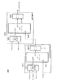
図9は、本実施形態における原稿種別判定部118の構成例を示すブロック図である。
本実施形態において、原稿種別判定部118は、無彩色/有彩色判定手段115が出力する色判定信号KCを順次計算して、原稿がモノクロなのか、カラーなのかを判定する。
【0080】
まず、無彩色/有彩色判定部115から順次送られてくる無彩色/有彩色判定信号KCは、原稿種別判定部を実施する有効領域か否かを識別領域制限部901にて制限する。識別領域制限部901は、領域制限係数記憶部119に記憶された領域制限係数に従って、図19に示すように原稿全読み取り領域1801に対し、主走査方向に(a,b)、副走査方向に(c,d)のように領域に制限を与える。これにより、図19の斜線の部分1802に相当する判定信号が有効な判定信号KCとして、後段の処理へと入力される。
【0081】
このとき主走査方向の領域制限は、上記に示すように、例えば起点アドレスaを与えた後、終点アドレスbを与える方法であっても良いし、起点アドレスaと主走査方向の検知幅awを与えても同様の効果が得られるため、どちらの方法を使用してもよい。
【0082】
また、副走査方向の領域制限を与えるものとして、副走査の起点アドレスcと、終点アドレスdを与えることにより検知すべき領域制限が確定する。このとき、副走査方向の領域制限は、起点cを与えた後、主走査方向と同様に副走査幅bwにより制限しても良いが、複写の際に操作者から指示される原稿サイズ、もしくは本実施形態では説明していない自動原稿送り装置(ADF,RDF)などの原稿検知結果に応じて副走査方向の領域制限を与えても良い。
【0083】
尚、ここで領域制限を与えるアドレスは、上述のように領域制限係数記憶部119に記憶しておき、例えば主走査ラインを認識できる主走査同期信号:HSYNC、副走査同期信号:VSYNC、それに1画素毎に同期した信号であるビデオクロック:VCLKとから領域の制限を内部カウンタ(不図示)のカウンタ値にて制限を設ける。
【0084】
よって、原稿領域制限手段901は、カウンタ値が所定の範囲(判定領域内:1802)であれば、そのままKC信号を送出するが、領域外は、判定に寄与させないために、無彩色信号としてKC信号を変更して送出する。
【0085】
このように領域を制限して原稿種別判定を行う理由は、原稿をスキャナが読み取る際に、画先や終端領域にある、スキャナ固有が有する動作振動を受けてしまったり、主走査の端部がレンズのMTF差、収差の影響を受けることにより、読み取られた信号が上述した色ずれ(例えば、黒の細線領域の縁が色づく)を起こし、その結果として生じる誤判定(モノクロ原稿内の黒の細線の縁の色を検知して、原稿を色原稿として判定してしまう)や、原稿上にない領域の色を検知してしまうために、結果的に生じてしまう誤判定を防ぐためである。
【0086】
本実施形態ではさらに、領域制限された信号を主走査方向の判定結果(主走査カウント部)と、副走査方向の判定結果(副走査カウント部)をもとに最終的な判定を行う特徴をもつ。
【0087】
(主走査方向の判定処理)
始めに、主走査方向に有彩色が存在することを判定する部である主走査カウント部903につながる処理について説明する。
【0088】
領域制限を受けた無彩色/有彩色信号KCは、IRO_ACS信号として出力され、第1主走査色群認識部902にて、主走査方向に連続した有彩色画素の固まりが所定数以上あるか否かを判定する。構成例を図10に示す。
【0089】
図10において、第1主走査色群認識部902は、主走査方向に有彩色と判定された画素が所定数M(≧0)連続しているかの判定を行う主走査連続性認識部1001と、主走査連続性認識部1001が認識した、M画素連続した有彩色画素の固まりを、色の固まりとして認識する色群認識部1002とから構成される。第1主走査色群認識部902にて判定された結果は、その結果をCOL_EXIST_M(1ビット)信号として、後段の主走査カウント部903に送出する。
【0090】
まず、主走査連続性認識部1001について説明する。まず、このような主走査に有彩色画素の連続性を観測する理由は、例えば図11に示すように、黒い縦線1101のエッジ(1102、1103:図のグレー部分)において、何らかの理由(レンズのMTF差、収差、ミラー台の振動など)で、主走査方向に色ずれが発生した場合に、本来無彩色領域にも関わらず、エッジ1102、1103に偽色が発生し、有彩色画素が副走査方向に縦線1101の長さ分だけ存在することになる。
【0091】
その結果生じる誤判定部分を間違ってカウントしてしまうと原稿の種別検知(カラー原稿かモノクロ原稿か)を誤って判定しまうため、本処理のような主走査方向の連続性の認識処理を組み込んで、誤判定を回避している。
【0092】
続いて主走査連続性認識部1001の処理について説明する。
まず、処理の開始時に連続性を観測するためのカウンタ1011をリセットする。本実施形態では、有彩色の連続度を観測するのに、アップカウンタを想定している。よって、連続度を認識するために、副走査同期信号(VSYNC)と、主走査同期信号(HSYNC)とのタイミングにより、コピーシーケンスの動作の始まりか、もしくは、スキャナ動作の始まりを示す動作タイミングに合わせて、内部のアップカウンタをリセットする。
【0093】
また、内部のカウンタは、連続した有彩色判定信号を観測するので、有彩色が連続していない場合は、その都度、リセットされ、さらに、主走査方向に有彩色の存在を観測する目的から、1主走査ラインの終了時にもリセットされ、計3つの条件で内部カウンタはリセットされることになる。リセット信号生成部1010は、VSYNC,HSYNC及びIRO_ACS信号から、上述した条件に従ってカウンタ1011のリセット信号を生成し、カウンタ1011のリセット端子に供給する。
【0094】
内部カウンタの値は、1ビデオクロック(VCLK)毎に増加し、リセットされずにカウンタ値が、所定のカウント値(M、M>0とする)に達すると、カウント値と所定値Mとを比較するコンパレータ1012が検出信号を発生する。所定値Mは、後述するROM122に記憶されている。
【0095】
図12を用いて、主走査連続性認識部1001の動作についてさらに説明する。ここでは、例えば1主走査ライン上のある9画素の判定信号の処理に着目して説明を行う。図のマスは1画素における無彩色/有彩色判定信号KCの結果を示し(厳密には、領域制限をうけたIRO_ACS信号を示す)、白いマスは有彩色と判定された画素、黒いマスは無彩色と判定された画素を表す。図では、N−4が古い時刻の結果、N+4が新しい時刻の判定結果を示す。
【0096】
本実施形態に示す主走査連続性認識部1001の内部カウンタ1011は、N−4からNまでの4画素については連続してカウントアップされ、N+1の画素で無彩色と判定されたIRO_ACS信号を観測することにより、リセット信号発生部1010がリセット信号を発生し、内部カウンタ1011をリセットする。そして、有彩色画素のN+2画素から再びカウントを開始し、N+3画素までカウントすると、N+4画素が無彩色と判定された画素なので、再び内部カウンタはリセットされる。
【0097】
このようなカウント動作の間、カウント値が所定値Mに達すると、コンパレータ1012から色群認識処理部1002内部のカウンタ1021をカウントアップするパルス信号が出力される。このパルス信号はまた、主走査連続性認識部1001のカウンタ1011のリセット信号としても用いられ、これにより再度M画素連続した有彩色画素の有無が判定される。
【0098】
また、本実施形態で用いた内部カウンタ1011は、有限のビット数で構成されているので、カウンタ値OUTが最大値を示した場合には、それ以上カウントアップしないように制限を持たせている。
【0099】
続いて、主走査色群認識処理内の色群認識処理部1002について説明する。色群認識処理1002も、主走査連続性認識部1001と同様に、内部にアップカウンタ1021と、カウンタ1021のカウント値を所定の閾値MGと比較するコンパレータ1022及びリセット信号生成部1020とから構成されている。
【0100】
主走査連続性認識部1001が所定の連続度Mの有彩色画素を検出すると、コンパレータ1012が出力するパルス信号により、色群認識処理1002内部のカウンタ1021がカウントアップする。そして、コンパレータ1022によって、カウンタ1021のカウント値と所定の値MG(後述のROM122内に設定された値)と比較後、所定の値以上であれば、注目する主走査ラインに有彩色の固まりが存在したことを知らせる:COL_EXIST_M信号にビット”1”を立てる。そうでない場合は、COL_EXIST_Mは、有彩色の固まりが無いもとのして、ビットは”0”を立て、後段の主走査カウント部に注目するラインにおける色の存在を知らせる。
【0101】
リセット信号生成部1020は、主走査連続性認識部1001のリセット信号生成部1010と同様、VSYNC及びHSYNC信号から、1主走査ラインの終了時及び、コピーシーケンスの動作の始まり、スキャナ動作の始まりを示す動作タイミングに合わせて、カウンタ1021のリセット信号を発生する。
【0102】
次に、色群認識部1002の具体的な動作を、図13を用いて説明する。
図13のマスは、図12で説明したものと同様に、白が有彩色と判定された画素を、黒が無彩色と判定された画素を示す。
ここでは、動作内容をわかりやすくするために、主走査連続性認識部1001の動作とあわせて説明する。また、主走査連続性認識部1001で検出する連続度Mが”2”、色群認識部1002で色の固まりを認識するパラメータMGが”3”であるものとして動作の説明を進める。
【0103】
図13の例では、主走査連続性を認識する内部カウンタ1011は、有彩色画素N−4、N−3によりカウンタ値が2を示すので、コンパレータ1012がパルス信号を発生し、色群認識部1002内部のカウンタ1021は、カウントアップし、1となる。コンパレータ1012のパルス信号はカウンタ1011のリセット信号として用いられるので、カウンタ1021がカウントアップした後にリセットされる。
【0104】
続いて、N−1で再び、カウンタ1011のカウンタ値が”2”に達するので、カウンタ1021はカウントアップしてカウンタ値は2となる。N+1画素が無彩色のため、その時点でカウンタ1011はリセットされ、次にN+3画素のときに、カウンタ1021のカウンタ値が3にカウントアップされる。この時点で、コンパレータ1022は、カウント値がMGと同じ値になったので、COL_EXIST_M信号に”1”を立てて、注目するラインに色が存在したことを後段の主走査カウント部903に知らせる。また、COL_EXIST_Mの値は、一度”1”になると、カウンタ1021の値が同じ主走査ラインに対する処理では減ることが無いため、その主走査ラインに対しては”1”が保持される。
【0105】
尚、図13において、N+8画素まで処理したときの、カウンタ1011とカウンタ1021のカウンタ値は、それぞれ、”2”、”5”となり、カウンタ1011はリセットされる。カウンタ1021もカウンタ1011と同様に有限のビットで構成されているので、カウンタ値が最大の値を示したときは、それ以上カウントアップしないように制限を持たせている。
【0106】
また、上述のように、カウンタ1021は、カウンタ1011と同様に、コピーシーケンスの動作時、スキャンの動作時、さらに1主走査ライン毎にリセットされる。
以上、第1主走査色群認識部902の動作内容を説明した。このように第1主走査色群認識部902は、注目する主走査ライン上に、先ず所定数の有彩色画素の連続度と、その連続した固まりが所定の数だけ存在したか否かを判定するものである。
【0107】
続いて、主走査カウント部903について説明する。
図14に示すように、主走査カウント部903も、基本的な構成は主走査連続性認識部1001や色群認識部1002と同様に、アップカウンタ911及びリセット信号生成部910によって構成されている。
【0108】
カウンタ911のリセットは、コピーシーケンスの動作初期、スキャンの動作初期に行われ、第1主走査色群認識部902のカウンタ1011、1021の様な、1主走査ライン毎のリセットは行わない。リセット信号生成部910は、VSYNC及びHSYNC信号から、これら所定のタイミングでカウンタ911をリセットするリセット信号を生成する。
【0109】
カウンタ911のカウントタイミングは、1主走査ライン内の処理で、第1主走査色群認識部902の処理が終了し、COL_EXIST_Mの値が確定した時となる。
つまり、1主走査ライン上で、設定された連続度Mを有する有彩色画素の固まりがMG回検出され、注目するラインに色の存在が確定した後にカウントされる。
【0110】
このとき、第1主走査色群認識部902内部のカウンタ1021は、主走査カウント部903のカウントが終了するまで、リセットされない。
また、主走査カウント部903内部のカウンタ911は、主走査色群認識部902内部のカウンタ群と同様に、カウント値が最大値になったら、それ以上カウントしないように制限されている。
以上が、主走査方向の判定処理に関する説明である。
【0111】
(副走査方向の判定処理)
続いて、副走査方向の判定処理について図15〜図17を用いて説明する。
副走査方向の判定処理は、主走査方向と同様に、第2主走査色群認識部904(副走査用)と副走査カウント部905から構成される。副走査方向の判定処理の特徴は、注目するラインに色画素の固まりの存在を認識したら、副走査方向にその連続性を観測することによって、副走査方向の色の存在を認識することである。
【0112】
まず、第2主走査色群認識部904について、図15を用いて説明する。
第2主走査色群認識部904は、主走査方向の判定部に用いられた第1主走査色群認識部902と全く同じ構成を有する(コンパレータ1012で比較される連続度MがSに、コンパレータ1022で比較される連続度MGがSGに、色群認識手段の出力COL_EXIST_MがCOL_EXIST_Sへそれぞれ変化することを除き、図15中の1401は、図10中の1001と、図15中の1042は、図10中の1002と同様の回路構成を有する)。
【0113】
本実施形態の特徴でもあるが、このように主走査、副走査の判定処理に、同一の処理を行う構成を用いている理由は、主走査、副走査の各処理判定において、処理に用いるパラメータを独立して設定可能とすることにより、異なる判定精度を持たせるためにある。よって、本実施形態では、副走査判定用の連続度を認識するパラメータSとSGは、主走査判定用のMとMGとは異なる値を持つことができる。
【0114】
続いて、副走査カウント部905の処理を、図16、17を用いて説明する。図16は、副走査カウント部905の内部処理ブロックを表すものである。
まず、副走査カウント部905内部の副走査連続性認識部1501について説明する。
副走査連続性認識部1501は、主走査連続性認識部1001と同様、内部カウンタ1511とコンパレータ1512及びリセット信号生成部1510で構成されている。
【0115】
まず、前段の第2主走査連続性認識部904から送出されたCOL_EXIST_Sの値を、1主走査ラインにおける判定結果が確定した後にカウントする。
このとき、主走査連続性認識部1001で連続度を認識したのと同様に、コンパレータ1512によって、副走査方向の連続度を認識する(閾値lineと比較する)。
比較の結果、カウンタ1511の値が、閾値を超えていれば、後段の副走査方向カウント部1502のカウンタ1521にてカウントアップする。
【0116】
副走査連続性認識部1501が有するリセット信号生成部1510は、コピーシーケンスの動作初期、スキャンの動作初期にカウンタ1511をリセットするリセット信号を生成する。カウンタ1511はまた、コンパレータ1512が副走査方向カウント部1502のカウンタ1521をカウントアップする信号によってもリセットされる。
【0117】
同様に、副走査方向カウント部1502が有するリセット信号生成部1520は、コピーシーケンスの動作初期、スキャンの動作初期にカウンタ1521をリセットするリセット信号を生成する。
【0118】
次に、図17を用いて副走査カウント部905の処理について説明する。図17においてN−4からN+8は主走査方向の画素位置を表し、M−4からM+3は、副走査方向のライン数を表し、白いマス目は有彩色と判定された画素を、黒いマス目は無彩色と判定された画素を表す。
動作をわかりやすく説明するために、連続性を判定するための閾値を、S=3、SG=2、line=3と設定する。
【0119】
N−4画素で1主走査ラインが始まり、N+8画素で1主走査ラインが終了するとすると、第2主走査色群認識部904において、N−4画素からN−2画素、N−1画素からN+1画素において、有彩色画素が3連続するため、この時点でCOLOR_EXIST_Sが1になり、ラインが終了した時点でM−4ラインにおける副走査連続性認識部1501の内部カウンタ1511はインクリメントされ1となる。
【0120】
続いて、M−3、M−2ラインもM−4ラインと同一パターンであるため、カウンタ1511のカウント値は3となる。このとき、コンパレータ1512により閾値line(=3)に達したことが検出され、副走査方向カウント部1502の内部カウンタ1521はカウントアップする。カウンタ1521のカウントアップが確定すると、コンパレータ1512の出力信号によってカウンタ1511はリセットされる。
【0121】
引き続き、M−1ラインにおいても3連続の有彩色画素が2回検出されるため、COLOR_EXIST_Sが1になり、ラインが終了した時点でM−1ラインにおける副走査連続性認識部1501の内部カウンタ1511はインクリメントされ1となる。同様に処理を続け、M+1ラインでカウンタ1511のカウント値が3となったところで、再びコンパレータ1512によってカウンタ1521がインクリメントされ、カウンタ値は2となる。
【0122】
また、副走査カウント部905内部にあるカウンタ1511及び1512は、いずれもカウンタが最大値を示すと、それ以上カウントアップしないように制限を持たせている。
以上、副走査カウント部905ならびに、副走査方向の判定処理に関する説明である。
【0123】
このように、主走査、副走査方向の判定部による結果が確定(1スキャン終了を示し、これは、フォワードスキャンでもバックスキャンのいずれでもよい)すると、それぞれのカウント結果を識別部906で観測する。
【0124】
識別部906は、主走査カウント部903のカウント値MAIN_UC及び副走査カウント部905SUB_UCから、所定の判定条件に従って原稿がモノクロかカラーかを判定する。
【0125】
判定条件は任意に決定可能であるが、例えば主走査、副走査のカウント結果のいずれかの値が1以上になっていれば、原稿中に色が存在しているとして、読み込まれた原稿をカラー処理専用の処理に設定して、所定の画像処理を実施することになる。あるいは、主走査カウント部903のカウント値が1以上で、かつ副走査カウント部905のカウント値が3以上の場合カラー原稿と判断することもできる。このように、副走査カウント部のカウント値を組み合わせることによって、黒色の輪郭に発生する偽色を誤検出する可能性が削減できる。
【0126】
識別部906で、原稿がカラーと判定されれば、カラートナーを用いる等の画ラー画像に適した画像処理を行い、プリンタ部200でカラーの画像形成処理が行われる。又、原稿がモノクロと判定されれば、黒色トナーのみを用いる等、モノクロ処理に最適な画像処理がなされ、プリンタ部200で画像形成処理が行われる。
【0127】
尚、本実施形態において図1(a)として示した画像処理部209は、各部をハードウェアで構成することも可能であるが、例えば図1(b)に示すように、CPU121がROM122に記憶されたプログラムを、RAM123をワークエリアとして用いて実行する構成でも実現することができる。この場合、イメージスキャナ部201及びプリンタ部200とのやりとりは入出力部124を介して行う。RAM123はCPU121のワークエリアとしてのみならず、イメージスキャナ部201から読み込んだ画像データや、プリンタ部200へ送信する印刷データの一次保存場所としても用いられる。また、RAM123以外の読み書き可能な記憶装置として、ハードディスクドライブ等の外部記憶装置を用いることも可能である。
【0128】
また、図1(a)の各部のうち、CPU処理の負荷が大きな部分のみハードウェアで構成し、それ以外の部分をCPUがプログラムを実行することで実現することも可能であることは言うまでもない。
【0129】
以上説明したように本実施形態によれば、色ずれの発生によりモノクロ原稿内の黒の細線の縁が色ずれしても、その色ドットの計数方法工夫することで、原稿の種別検知を高い精度で行うことができる。詳しくは、主走査、副走査方向の判定方法において、色ドットの連続性を観測することで、従来のような単純加算による方法に比べ、色ずれに対しラチチュードの高いアルゴリズムが実現できた。さらに、主走査、副走査方向に判定する連続度の精度を独立して設定することができるため、スキャナの機種毎、あるいは1台毎に適切な閾値を設定することが可能になり、さらにラナチュードを広くもつことができた。
【0130】
尚、実施形態で説明した各判定のための閾値は、動的に適宜変更可能としてもよい。変更するタイミングとしては、例えば原稿画像のサイズを検知する部を備え、その検出部からの信号によるなどが考えられる。
【0131】
また、閾値をイメージスキャナ部の特性(読み取り位置ずれの量など)によって設定することによって、イメージスキャナ部の個体差に影響されずに精度の高い判定が可能になるほか、イメージスキャナ部を交換可能もしくは複数のイメージスキャナ部から選択して使用可能な場合などであっても常に適切な判定が可能になる。
【0132】
【他の実施形態】
尚、本発明は、複数の機器(例えばホストコンピュータ、インターフェイス機器、スキャナ、プリンタなど)から構成されるシステムに適用しても、上記の如く、一つの機器からなる複写機に適用してもよい。
【0133】
また、本発明の目的は、前述した実施形態の機能を実現するソフトウェアのプログラムコードを記録した記憶媒体(または記録媒体)を、システムあるいは装置に供給し、そのシステムあるいは装置のコンピュータ(またはCPUやMPU)が記憶媒体に格納されたプログラムコードを読み出し実行することによっても、達成されることは言うまでもない。この場合、記憶媒体から読み出されたプログラムコード自体が前述した実施形態の機能を実現することになり、そのプログラムコードを記憶した記憶媒体は本発明を構成することになる。また、コンピュータが読み出したプログラムコードを実行することにより、前述した実施形態の機能が実現されるだけでなく、そのプログラムコードの指示に基づき、コンピュータ上で稼動しているオペレーティングシステム(OS)などが実際の処理の一部または全部を行い、その処理によって前述した実施形態の機能が実現される場合も含まれることは言うまでもない。
【0134】
さらに、記憶媒体から読み出きれたプログラムコードが、コンピュータに挿入された機能拡張カードやコンピュータに接続された機能拡張ユニットに備わるメモリに書き込まれた後、そのプログラムコードの指示に基づき、その機能拡張カードや機能拡張ユニットに備わるCPUなどが実際の処理の一部または全部を行い、その処理によって前述した実施形態の機能が実現される場合も含まれることは言うまでもない。
【0135】
【発明の効果】
以上説明したように本発明によれば、色ずれの発生(読み取り位置ずれ等)があったとしても精度良く入力画像がカラー画像であるか、モノクロ画像であるかを識別することが可能になり、さらには、スキャナーの個体差に応じて、主走査、副走査方向の判定精度を可変にすることにより、使用できるスキャナの許容範囲が広い判定処理を実現できる。
【0136】
【図面の簡単な説明】
【図1】本発明の実施形態に係る画像処理装置としての、画像処理部の構成例を示すブロック図である。
【図2】図1の空間フィルタ係数記憶部が記憶する空間フィルタ係数の例を示す図である。
【図3】図1のエッジ強調量分配部で行う明度信号に対するエッジ強調補正量生成処理を示すフローチャートである。
【図4】図3の処理に基づくエッジ強調補正量を示す図である。
【図5】図1のエッジ強調量分配部で行う色度信号に対するエッジ強調補正量生成処理を示すフローチャートである。
【図6】図5の処理に基づくエッジ強調補正量を示す図である。
【図7】本発明の実施形態において、色度信号のエッジ強調実施前後で色味(色相)が保存されることを示す図である。
【図8】図1における遅延部の構成例及び関連する他部との接続関係を示すブロック図である。
【図9】図1における原稿種別判定部の構成例を示すブロック図である。
【図10】図9における第1主走査色群認識部の構成例を示すブロック図である。
【図11】色ずれを説明する図である。
【図12】図10における主走査連続性認識部の動作を説明するための、IRO_ACS信号の出力例を示す図である。
【図13】図10における色群認識部の動作を説明するための、IRO_ACS信号の出力例を示す図である。
【図14】図9の主走査カウント部の構成例を示すブロック図である。
【図15】図9のにおける第2主走査色群認識部の構成例を示すブロック図である。
【図16】図9の副走査カウント部の構成例を示すブロック図である。
【図17】図16における副走査カウント部の動作を説明するためのIRO_ACS信号の出力例を示す図である。
【図18】本発明の実施形態に係る画像処理装置を適用可能な画像形成装置の一例であるカラー複写機の構成例を示すブロック図である。
【図19】図9における原稿領域制限部により、制限された原稿読み取り領域の例を示す図である。[0001]
BACKGROUND OF THE INVENTION
The present invention relates to an image processing apparatus andImage processingFor details on the method, identify whether the input image is a color image or a monochrome imageforImage processing apparatus andImage processingAbout the method.
[0002]
[Prior art]
In a color image forming apparatus, in particular, a color copying machine realized by combining a color copying machine, a color scanner, a computer, and a color printer, C (cyan), There are cases where copying is performed with four colors of M (magenta), Y (yellow), and K (black). However, in the case of a color copying machine or a color copying apparatus using a color laser beam printer, it is desirable to copy a monochrome original with a single black color considering the life of the drum and the amount of toner consumption. This is the same as color copiers and copiers using color ink jet printers, considering the ink consumption.
[0003]
For this reason, a color image forming apparatus is desired to have a function for identifying whether a document image is a color document or a monochrome document. Conventionally, such document type discrimination is mainly performed by adding color pixels (pixels determined to be chromatic) of an input document, and statistically evaluating the added value or comparing it with a threshold value. It was done by simple evaluation.
[0004]
[Problems to be solved by the invention]
However, when the color pixel is determined based on the color component for each pixel of the document image read by the document input device (in the present invention, R, G, B luminance signals), the color component at the same position. When the reading element that should read is not able to read the exact same pixel position, that is, when reading is performed with a slight shift (hereinafter referred to as color shift), the edge of the black line is colored Will be detected as there is.
[0005]
In particular, recently, the reading accuracy (resolution) of an image scanner used as an image input apparatus has only been increased, and the above problems are often highlighted.
[0006]
Even if the reading position accuracy is sufficient, the color component (false color) similar to the case where the reading position accuracy is insufficient is generated near the edge of the black line due to variations in MTF characteristics for each wavelength by the lens. Resulting in. As described above, it can be understood from the above reason that the generation of the pseudo color component due to the color misregistration or the MTF characteristic of the lens does not cause a problem when a uniform color original (for example, a white paper) is read. .
[0007]
The problem is that a false color generated due to a color shift or a variation in the MTF characteristics of the lens near the edge of a black character or a black thin line is determined to be “chromatic” although it should be originally achromatic.
[0008]
However, in this process, the determination accuracy in the main and sub-scanning directions is changed because the continuity in the main scanning direction and the threshold for determining the cluster of the continuous color pixels are the same for counting in the main and sub-scanning directions. In some cases, it was impossible to make an optimal determination that reflected the characteristics of the image scanner and individual differences.
[0009]
The present invention has been made in view of such problems of the prior art, and its purpose is as follows.It is possible to accurately identify whether the input image is a color image or a monochrome imagePossible image processing device andImage processingIt is to provide a method.
[0011]
[Means for Solving the Problems]
That is, the gist of the present invention is as follows.PaintingMain scan line of imageInChromatic pixelThere is a mass ofDetermine ifIn addition, it is determined whether there is a predetermined number or more of chromatic color pixels.First determining means to perform,It is determined whether there is a cluster of chromatic pixels in the main scan line of the image, and whether there are continuous main scan lines in the sub-scan direction that are determined to have a cluster of chromatic pixels.Second judging means for judging andHaveFirst determination meansas well asSecond judgeIn stepsJudgment resultAre both positive,in frontDrawingThe image is a color imageWhenjudgeAn image processing apparatus,firstofJudgment meansBoth the second determination means determine whether chromatic color pixels exist continuously for a threshold value or more in order to determine whether there is a cluster of chromatic color pixels. And the threshold value used in the second determination means are:It exists in the image processing apparatus characterized by being set independently.
[0012]
Another gist of the present invention is as follows.PaintingMain scan line of imageInChromatic pixelThere is a mass ofDetermine ifIn addition, it is determined whether there is a predetermined number or more of chromatic color pixels.A first determination step,It is determined whether there is a cluster of chromatic pixels in the main scan line of the image, and whether there are continuous main scan lines in the sub-scan direction that are determined to have a cluster of chromatic pixels.A second determination step for determining andHaveFirst judgment processas well asSecond judgeIn stepsJudgment resultAre both positive,in frontDrawingThe image is a color imageWhenjudgeAn image processing method comprising:firstofJudgment processIn both of the second determination step, in order to determine whether there is a cluster of chromatic color pixels, it is determined whether chromatic color pixels are continuously present above a threshold, but are used in the first determination step. And the threshold used in the second determination step areAn image processing method is characterized by being set independently.
[0014]
DETAILED DESCRIPTION OF THE INVENTION
[Embodiment 1]
Hereinafter, embodiments according to the present invention will be described in detail with reference to the drawings.
FIG. 18 is a cross-sectional view showing a structural example of a color image forming apparatus as an example of an image forming apparatus to which the image processing apparatus according to the embodiment of the present invention can be applied.
[0015]
In the figure,
[0016]
In the
[0017]
Reflected light from the original 204 is guided to
[0018]
In the present embodiment, the
[0019]
The
[0020]
A reference
[0021]
The details of the
[0022]
The Y, M, C, and Bk image signals sent from the
[0023]
[0024]
A
The above is the outline of the operation of the color copying machine shown in FIG.
[0025]
In addition, in order to perform multiple recording on the back side of the recording paper, a branch conveyance path is provided at the paper discharge port as shown in the figure. By taking in the apparatus again through this conveyance path, it is possible to perform recording on the back surface, multiple recording, and the like.
[0026]
(Configuration of image processing unit)
FIG. 1A is a block diagram mainly showing a functional configuration of the
A G1 signal that is one of the three-color separation signals R1, G1, and B1 of the image read by the
[0027]
The character /
[0028]
The character / image determination signal TI is output to the black character / color character / image determination
[0029]
FIG. 2A and FIG. 2B are diagrams showing an example of the spatial filter coefficients Kij for characters and gradation images stored in the spatial filter coefficient storage unit 112. The DC component of the conventional spatial filter for characters and gradation images is “1”, whereas the spatial filter for characters or gradation images in this embodiment is shown in FIG. In b), the DC component is set to “0”. That is, for a flat image having no edge component, the output after the conventional spatial filtering outputs the input image value as it is, whereas the output value after the spatial filter processing of this embodiment is “0”.
[0030]
Returning to FIG. 1A, the three signals of the three color separation signals R1, G1, and B1 of the color image are input to the first color
[0031]
The following equation (1) shows an example of a conversion equation for simply converting the three color separation signals R, G, and B into lightness and chromaticity signals L1, Ca1, and Cb1.
L = (R + 2G + B) / 4
Ca = (RG) / 2 Formula (1)
Cb = (R + G-2B) / 4
[0032]
The lightness signal L1 and the chromaticity signals (Ca1, Cb1) converted by the first color
[0033]
The edge enhancement
[0034]
5 × 5 brightness signal L1ijWhen expressed by (i = 1 to 5, j = 1 to 5), the edge enhancement amount ε is obtained as follows.
ε = (ΣL1ij* Kij) / C
(Here, * is a multiplication, and C is a normalization constant that normalizes the edge-emphasized component.)
[0035]
This edge enhancement amount ε is supplied to the edge enhancement amount distribution unit 116. The edge enhancement amount distribution unit 116 is based on the edge enhancement amount ε, the saturation signal S from the saturation
[0036]
Although not shown in FIG. 1, the chromaticity signals (Ca1, Cb1) delayed by the
[0037]
Here, a method for generating the saturation signal S from the chromaticity signals (Ca1, Cb1) will be briefly described. The chromaticity signal (Ca1, Cb1) is a signal (a *, b *) in the CIE 1976 (L *, a *, b *) color space or a signal in the CIE 1976 (L *, u *, v *) color space. When (u *, v *), the saturation signal S is determined by equation (2). In the equation, the symbol “^” represents a power.
S = (Ca1 ^ 2 + Cb1 ^ 2) ^ 0.5 Formula (2)
[0038]
Further, for simplicity, the saturation signal S may be determined by the equation (3).
S = MAX (Ca1, Cb1) Formula (3)
Here, the function MAX (A, B) outputs a value having a larger absolute value of the variables A and B.
[0039]
In addition to the edge enhancement amount ε and the saturation signal S, the edge enhancement amount distribution unit 116 also receives a determination signal KC from an achromatic / chromatic
[0040]
The achromatic / chromatic
[0041]
However, as described above, the saturation signal S is generated by the saturation
[0042]
Hereinafter, the
[0043]
Since the lightness signal L1 and the chromaticity signals (Ca1, Cb1) output from the first color
[0044]
Now, assuming that the center line is j line, the lightness signal L1 stores j-2, j-1, j, j + 1 lines, and the lightness signal for five lines including the current line j + 2 lines is the edge enhancement amount extraction unit. 113 is input.
[0045]
The
[0046]
On the other hand, for the chromaticity signals Ca1 and Cb1, the
[0047]
Further, in the present embodiment, the saturation signal S is calculated for the three lines j, j + 1, and j + 2 by using the above-described equations (2) and (3) when calculating the achromatic / chromatic color determination signal KC. It is also possible to perform spatial processing using this data. For example, the saturation signal S can be obtained by averaging the saturation signals of adjacent pixels (8 pixels) of 3 × 3 size surrounding the target pixel, and the average value can be represented by the saturation signal S. Similarly, for the chromatic color determination signal KC, the determination result of the adjacent pixels of 3 × 3 size may be statistically processed, and the representative value may be the achromatic / chromatic color determination signal KC.
[0048]
(Calculation of color determination signal KC)
Next, a method for calculating the determination signal KC based on the obtained saturation signal S will be described.
When the saturation signal S is small, the pixel is black and white (achromatic color). When the saturation signal S is large, the pixel is color (chromatic color). Therefore, simply, the determination signal KC is determined by Expression (4) using a predetermined threshold ρ.
(When S <ρ) KC = Achromatic
(When S ≧ ρ) KC = chromatic color Formula (4)
[0049]
(Generation of edge enhancement correction amount for brightness signal)
Hereinafter, a process of generating the edge enhancement correction amounts εl and εc based on the edge enhancement amount ε, the saturation signal S, and the determination signal KC input to the edge enhancement amount distribution unit 116 will be described.
[0050]
First, the distribution of the edge enhancement correction amount ε with respect to the lightness signal L1 is increased, and the total edge enhancement amount ε is assigned to εl for achromatic signal pixels. Further, edge correction for the brightness signal is not performed for pixels having a saturation equal to or higher than a predetermined value.
[0051]
This process will be described with reference to the flowchart of FIG. 3 and the schematic diagram of FIG.
In step S1 shown in FIG. 3, the process branches according to the achromatic / chromatic determination signal KC of the target pixel. When the determination signal KC is achromatic (when the determination in step S1 is YES), “1” is assigned to the multiplication coefficient γ in step S2 in order to assign the total edge enhancement amount ε to ε1, and εl = γε in step S6. That is, ε is assigned to εl.
[0052]
If the determination signal KC is a chromatic color in step S1, it is determined whether or not the saturation signal S is greater than a predetermined value η (step S3). “0” is assigned (step S4), and in step S6, γε, ie, “0” is assigned to εl.
[0053]
On the other hand, when the saturation S is equal to or less than η in step S3, it is difficult to determine whether the target pixel is a chromatic color or an achromatic color. Therefore, in step S5 and step S6, the multiplication coefficient γ and further εl are set. Determined by equation (5).
γ = (1− (S−α) / (η−α))
εl = (1 ((S−α) / (η−α)) ε (5)
[0054]
When the above processing is performed, the relationship among α, η, and γ is as shown in FIG. That is, γ is “1” when it can be determined that the color is substantially achromatic, and γ is “0” when it can be determined that the color is chromatic. In the intermediate state, a value of 0 to 1 (that is, a decimal point) is taken according to the saturation signal S as shown.
[0055]
(Generation of edge enhancement correction amount for chromaticity signal)
Next, the edge enhancement correction amount εc for the chromaticity signals (Ca1, Cb1) will be described.
[0056]
For chromaticity signals, contrary to that of lightness signals, the higher the saturation (brighter colors), the more the edge enhancement amount ε is distributed to the chromaticity signals, and for achromatic signal pixels. Then, edge correction is not performed, and the chromaticity signal of the target pixel is also removed.
[0057]
This is because in an image forming apparatus such as a color copying machine, if a color component remains in a copy image such as a black character, the image quality is visually deteriorated. In other words, for such a pixel, it is necessary to cut the color component and correct the color to a complete achromatic signal.
[0058]
This process will be described with reference to the flowchart of FIG. 5 and the schematic diagram of FIG.
In step S11 of FIG. 5, first, the process for the target pixel is switched in accordance with the achromatic / chromatic color determination signal KC. That is, when the determination signal KC indicates an achromatic color (when step S11 in the figure is YES), in order to set the edge enhancement amount εc to 0 as described above, the multiplication coefficient γ is set to 0 in step S12. Εc is set to 0 by performing the calculation of S18.
[0059]
If the determination in step S11 is NO, the process proceeds to step S13, and the saturation signal S is compared with the threshold value λ2. If S> λ2, the multiplication coefficient γ is set to 1 in step S14, the calculation in step S18 is performed, and εc is set to a value of (1−ε / κ).
[0060]
If it is determined in step S13 that S ≦ λ2, the process proceeds to step S15, where the saturation S and λ1 are compared to determine whether S <λ1. If the inequality is satisfied, it may be determined that the pixel of interest is an achromatic color, so the multiplication coefficient γ is set to 0 and εc is set to 0 in step S19.
[0061]
When it is determined in step S15 that S ≧ λ1, the multiplication coefficient γ is determined from the following equation in step S17 in order to set the multiplication coefficient γ to a value corresponding to the saturation signal S (a value between 0 and 1). To do.
γ = (S−λ1) / (λ2−λ1) Equation (6)
[0062]
In step S18, the edge enhancement correction amount εc for the chromaticity signal is obtained according to the equation (7).
εc = γ (1-ε / κ) Equation (7)
(Where κ is a normalization constant)
[0063]
As a result, the multiplication coefficient γ takes a value corresponding to the chromaticity signal S as shown in FIG. That is, the multiplication coefficient γ takes a value of “0” during an achromatic color (less than the threshold value λ1), and εc = 0. Further, γ = (S−λ1) / (λ2−λ1) when the saturation S is between the thresholds λ1 and λ2, and continuously increases as the saturation S increases. When the saturation S is higher than the threshold λ2, γ = 1, so εc = 1−ε / κ.
[0064]
The edge enhancement correction amounts εl and εc generated as described above are supplied to the
[0065]
The
L2 = εl + L1
Ca2 = εc * Ca1
Cb2 = εc * Cb1 Formula (8)
It becomes.
[0066]
As can be seen from the equation (8), by adding the edge correction amount εl to the signal L, the pixel having high chroma and not desired to be edge-enhanced becomes (εl = 0), and the lightness is preserved. . On the other hand, by multiplying the signals Ca and Cb by the edge correction amount εc, as the saturation is lower and the color is closer to an achromatic color, the εc gradually becomes a smaller value. , Εc = 0. That is, the lower the saturation value, the easier the removal of the chromaticity component of the target pixel itself is controlled.
[0067]
Here, the preservability of the hue (hue) with respect to the edge enhancement of the chromaticity signal will be described.
FIG. 7 represents chromaticity coordinates with the chromaticity signal (Ca1, Cb1) direction as a coordinate axis. For simplicity of explanation, the Ca and Cb axes are assumed to be a * and b * axes in the CIE 1976 (L *, a *, b *) color space.
[0068]
Further, the
[0069]
Now, when the target pixels are chromaticity signals Ca1 (702) and Cb1 (703), this color is represented by a
[0070]
When the edge enhancement processing is performed as described above, the signals L2, Ca2, and Cb2 are supplied to the second color
[0071]
The following equation (9) shows an example of a conversion equation for converting the lightness and chromaticity signals L2, Ca2, and Cb2 into the three-color separation signals R2, G2, and B2, and is obtained from the equation (1) described above. It is.
R2 = (4L + 5Ca + 2Cb) / 4
G2 = (4L-3Ca + 2Cb) / 4
B2 = (4L + Ca-6Cb) / 4 Formula (9)
[0072]
Thereafter, the three-color separation signal inversely converted into R2, G2, and B2 signals is input to the luminance / density conversion unit 106 and converted into density signals C1, M1, and Y1. Since the conversion from RGB to CMY color system itself is known, the method will not be described here.
[0073]
The density signals C1, M1, and Y1 are then subjected to background removal (known as UCR processing) by the
[0074]
In the present embodiment, the
The black character / color character / image determination
[0075]
For example, color correction is performed with emphasis on highlight color reproducibility for image signals, and color correction is performed on color characters and black character signals without highlight reproduction with the background color skipped. Similarly, the
[0076]
Note that the smoothing /
Each process is performed, and the C4, M4, Y4, and K4 signals that are the output of the smoothing /
[0077]
The image processing described above, which is a feature of the present embodiment, includes, for example, pre-scanning and back-scanning that are performed before the copying operation in the processing of the color copying machine (after the original is scanned once by the pre-scanning operation of the fluorescent lamp) Read operation in the process of returning to the home position), but if the image forming apparatus is equipped with a page memory, the document type in the normal reading sequence without pre-scanning It is also possible to make a determination.
[0078]
Hereinafter, the document
[0079]
FIG. 9 is a block diagram illustrating a configuration example of the document
In the present embodiment, the document
[0080]
First, the identification
[0081]
At this time, as shown above, the area limitation in the main scanning direction may be, for example, a method of giving the end point address b after giving the starting point address a, or setting the starting point address a and the detection width aw in the main scanning direction. Even if given, the same effect can be obtained, so either method may be used.
[0082]
Also, as the area restriction in the sub-scanning direction, the area restriction to be detected is determined by giving the sub-scan start point address c and end point address d. At this time, the area limitation in the sub-scanning direction may be limited by the sub-scanning width bw in the same manner as in the main scanning direction after giving the starting point c, or the document size designated by the operator at the time of copying, or An area limitation in the sub-scanning direction may be given according to a document detection result of an automatic document feeder (ADF, RDF) or the like not described in the present embodiment.
[0083]
Here, the address to which the region restriction is given is stored in the region restriction coefficient storage unit 119 as described above. For example, the main scanning synchronization signal that can recognize the main scanning line: HSYNC, the sub-scanning synchronization signal: VSYNC, and 1 The limit of the area is limited by the counter value of an internal counter (not shown) from the video clock: VCLK which is a signal synchronized for each pixel.
[0084]
Therefore, if the counter value is within a predetermined range (within the determination area: 1802), the document
[0085]
The reason for determining the document type by limiting the area in this way is that when the scanner reads the document, it receives an operation vibration inherent in the scanner in the image destination or the end area, or the end of the main scan is Due to the influence of the MTF difference and aberration of the lens, the read signal causes the above-described color shift (for example, the edge of the black thin line area is colored), and the resulting misjudgment (black in a monochrome document) The color of the edge of the thin line is detected and the document is determined as a color document), or the color of an area not on the document is detected, and thus erroneous determination that occurs as a result is prevented. .
[0086]
In the present embodiment, the region-limited signal is further subjected to final determination based on the determination result in the main scanning direction (main scanning count unit) and the determination result in the sub scanning direction (sub scanning count unit). Have.
[0087]
(Determination processing in the main scanning direction)
First, a process connected to the main
[0088]
The achromatic / chromatic signal KC subjected to the region restriction is output as an IRO_ACS signal, and the first main scanning color
[0089]
In FIG. 10, the first main scanning color
[0090]
First, the main scanning
[0091]
If the erroneously determined parts resulting from this are counted incorrectly, the document type detection (color document or monochrome document) will be erroneously determined, so a continuity recognition process in the main scanning direction like this process is incorporated. , Avoiding misjudgment.
[0092]
Next, processing of the main scanning
First, the
[0093]
In addition, since the internal counter observes a continuous chromatic color determination signal, if the chromatic color is not continuous, it is reset each time, and further, for the purpose of observing the presence of the chromatic color in the main scanning direction, It is also reset at the end of one main scanning line, and the internal counter is reset under a total of three conditions. The reset
[0094]
The value of the internal counter increases every video clock (VCLK), and when the counter value reaches a predetermined count value (M, M> 0) without being reset, the count value and the predetermined value M are A
[0095]
The operation of the main scanning
[0096]
The
[0097]
During the counting operation, when the count value reaches the predetermined value M, a pulse signal for counting up the
[0098]
In addition, since the
[0099]
Next, the color group
[0100]
When the main scanning
[0101]
Similar to the reset
[0102]
Next, a specific operation of the color
The squares in FIG. 13 indicate pixels for which white is determined to be a chromatic color, and pixels for which black is determined to be an achromatic color, as described with reference to FIG.
Here, in order to make the operation content easy to understand, the operation will be described together with the operation of the main scanning
[0103]
In the example of FIG. 13, the
[0104]
Subsequently, since the counter value of the
[0105]
In FIG. 13, the counter values of the
[0106]
Further, as described above, the
The operation content of the first main scanning color
[0107]
Next, the main
As shown in FIG. 14, the main
[0108]
The
[0109]
The count timing of the
That is, on one main scanning line, a cluster of chromatic color pixels having the set continuity M is detected MG times, and counted after the presence of color in the line of interest is determined.
[0110]
At this time, the
Similarly to the counter group in the main scanning color
The above is the description regarding the determination process in the main scanning direction.
[0111]
(Sub-scanning direction determination process)
Subsequently, determination processing in the sub-scanning direction will be described with reference to FIGS.
Similar to the main scanning direction, the sub-scanning direction determination process includes a second main scanning color group recognition unit 904 (for sub-scanning) and a
[0112]
First, the second main scanning color
The second main scanning color
[0113]
Although it is also a feature of this embodiment, the reason for using the same processing for the main scanning and sub-scanning determination processing is that the parameters used for processing in the main scanning and sub-scanning processing determination This is to provide different determination accuracy by enabling the setting independently. Therefore, in this embodiment, the parameters S and SG for recognizing the continuity for sub-scanning determination can have different values from M and MG for main-scanning determination.
[0114]
Subsequently, processing of the
First, the sub-scanning
Similar to the main scanning
[0115]
First, the value of COL_EXIST_S sent from the second main scanning
At this time, similarly to the case where the main scanning
As a result of the comparison, if the value of the
[0116]
A reset
[0117]
Similarly, a reset
[0118]
Next, processing of the
In order to easily explain the operation, thresholds for determining continuity are set as S = 3, SG = 2, and line = 3.
[0119]
When one main scanning line starts with N-4 pixels and one main scanning line ends with N + 8 pixels, the second main scanning color
[0120]
Subsequently, since the M-3 and M-2 lines have the same pattern as the M-4 line, the count value of the
[0121]
Subsequently, since three consecutive chromatic color pixels are detected twice in the M-1 line, COLOR_EXIST_S becomes 1, and when the line is completed, the
[0122]
In addition, the
The above is the description regarding the
[0123]
As described above, when the result of the determination unit in the main scanning and sub-scanning directions is confirmed (indicating the end of one scan, which may be either forward scan or back scan), each count result is observed by the
[0124]
The
[0125]
The determination condition can be arbitrarily determined. For example, if the value of one of the main scanning and sub-scanning count values is 1 or more, it is determined that a color exists in the original and the read original is Predetermined image processing is performed by setting processing dedicated to color processing. Alternatively, when the count value of the main
[0126]
If the
[0127]
In the present embodiment, the
[0128]
Further, it is needless to say that, among the units in FIG. 1A, only a part with a large CPU processing load is configured by hardware, and the other part can be realized by the CPU executing a program. .
[0129]
As described above, according to the present embodiment, even if the edge of a black thin line in a monochrome original is color-shifted due to the occurrence of color misregistration, the color type counting method is devised to increase the type detection of the original. Can be done with precision. Specifically, by observing the continuity of the color dots in the determination method in the main scanning and sub-scanning directions, an algorithm having a high latitude for color misregistration can be realized as compared with the conventional method using simple addition. Furthermore, since the accuracy of the continuity in the main scanning and sub-scanning directions can be set independently, it is possible to set an appropriate threshold value for each scanner model or for each scanner. Could have
[0130]
Note that the thresholds for each determination described in the embodiment may be dynamically changed as appropriate. As the timing of the change, for example, a part that detects the size of the document image is provided, and a signal from the detection part may be considered.
[0131]
In addition, by setting the threshold value according to the characteristics of the image scanner (such as the amount of reading position deviation), it is possible to make highly accurate judgments without being affected by individual differences in the image scanner, and the image scanner can be replaced. Alternatively, appropriate determination can always be made even when a plurality of image scanner units can be selected and used.
[0132]
[Other Embodiments]
The present invention may be applied to a system composed of a plurality of devices (for example, a host computer, an interface device, a scanner, a printer, etc.), or may be applied to a copying machine composed of a single device as described above. .
[0133]
Another object of the present invention is to supply a storage medium (or recording medium) in which a program code of software that realizes the functions of the above-described embodiments is recorded to a system or apparatus, and the computer (or CPU or CPU) of the system or apparatus. Needless to say, this can also be achieved by the MPU) reading and executing the program code stored in the storage medium. In this case, the program code itself read from the storage medium realizes the functions of the above-described embodiments, and the storage medium storing the program code constitutes the present invention. Further, by executing the program code read by the computer, not only the functions of the above-described embodiments are realized, but also an operating system (OS) running on the computer based on the instruction of the program code. It goes without saying that a case where the function of the above-described embodiment is realized by performing part or all of the actual processing and the processing is included.
[0134]
Further, after the program code read from the storage medium is written in a memory provided in a function expansion card inserted into the computer or a function expansion unit connected to the computer, the function expansion is performed based on the instruction of the program code. It goes without saying that the CPU or the like provided in the card or the function expansion unit performs part or all of the actual processing, and the functions of the above-described embodiments are realized by the processing.
[0135]
【The invention's effect】
As described above, according to the present invention, it is possible to accurately identify whether an input image is a color image or a monochrome image even if color misregistration (reading position misalignment, etc.) occurs. Furthermore, by making the determination accuracy in the main scanning and sub-scanning directions variable according to the individual difference of the scanner, it is possible to realize determination processing with a wide allowable range of usable scanners.
[0136]
[Brief description of the drawings]
FIG. 1 is a block diagram illustrating a configuration example of an image processing unit as an image processing apparatus according to an embodiment of the present invention.
FIG. 2 is a diagram illustrating an example of spatial filter coefficients stored in a spatial filter coefficient storage unit in FIG. 1;
FIG. 3 is a flowchart showing edge enhancement correction amount generation processing for a brightness signal performed by an edge enhancement amount distribution unit in FIG. 1;
4 is a diagram illustrating an edge enhancement correction amount based on the process of FIG. 3;
FIG. 5 is a flowchart showing edge enhancement correction amount generation processing for a chromaticity signal performed by an edge enhancement amount distribution unit in FIG. 1;
6 is a diagram showing an edge enhancement correction amount based on the processing of FIG.
FIG. 7 is a diagram showing that the hue (hue) is preserved before and after the edge enhancement of the chromaticity signal in the embodiment of the present invention.
8 is a block diagram illustrating a configuration example of a delay unit in FIG. 1 and a connection relationship with other related units.
9 is a block diagram illustrating a configuration example of a document type determination unit in FIG. 1. FIG.
10 is a block diagram illustrating a configuration example of a first main scanning color group recognition unit in FIG. 9;
FIG. 11 is a diagram illustrating color misregistration.
12 is a diagram illustrating an output example of an IRO_ACS signal for explaining the operation of the main scanning continuity recognition unit in FIG. 10;
13 is a diagram illustrating an output example of an IRO_ACS signal for explaining the operation of the color group recognition unit in FIG.
14 is a block diagram illustrating a configuration example of a main scanning count unit in FIG. 9. FIG.
15 is a block diagram illustrating a configuration example of a second main scanning color group recognition unit in FIG. 9. FIG.
16 is a block diagram illustrating a configuration example of a sub-scanning counting unit in FIG. 9;
FIG. 17 is a diagram illustrating an output example of an IRO_ACS signal for explaining the operation of the sub-scanning counting unit in FIG. 16;
FIG. 18 is a block diagram illustrating a configuration example of a color copying machine that is an example of an image forming apparatus to which the image processing apparatus according to the embodiment of the present invention can be applied.
FIG. 19 is a diagram illustrating an example of a document reading area restricted by the document area restriction unit in FIG. 9;
Claims (7)
前記画像の主走査ラインにおいて有彩色画素の固まりが存在しているか判定し、さらに、前記有彩色画素の固まりが存在すると判定された主走査ラインが副走査方向に連続して存在しているか判定する第二の判定手段とを有し、
前記第一の判定手段及び前記第二の判定手段による判定結果が共に肯定である場合に、前記画像がカラー画像であると判定する画像処理装置であって、
前記第一の判定手段及び前記第二の判定手段は、
共に、有彩色画素の前記固まりが存在しているか判定するために、有彩色画素が閾値以上連続して存在しているかを判定するが、前記第一の判定手段で用いられる前記閾値と、前記第二の判定手段で用いられる前記閾値とが、独立に設定されることを特徴とする画像処理装置。 It determines whether cluster of chromatic color pixels are present in the main scan lines of the images, further comprising: a first judging means for judging whether chunks of chromatic color pixel is present more than a predetermined number,
It is determined whether there is a cluster of chromatic pixels in the main scan line of the image, and further, it is determined whether main scan lines determined to have a cluster of chromatic color pixels are continuously present in the sub-scanning direction. and a second determination means for,
Wherein when the first judging means and the second determination hand by stages of positive determination result both before Kiga image a determined image processing apparatus as a color image,
Said first judging means and the second judging means,
Both determine whether chromatic color pixels are continuously present more than a threshold value in order to determine whether the cluster of chromatic color pixels exists, the threshold value used in the first determination means, An image processing apparatus , wherein the threshold used in the second determination means is set independently.
前記画像の主走査ラインにおいて有彩色画素の固まりが存在しているか判定し、さらに、前記有彩色画素の固まりが存在すると判定された主走査ラインが副走査方向に連続して存在しているか判定する第二の判定工程とを有し、
前記第一の判定工程及び前記第二の判定手段による判定結果が共に肯定である場合に、前記画像がカラー画像であると判定する画像処理方法であって、
前記第一の判定工程及び前記第二の判定工程は、
共に、有彩色画素の前記固まりが存在しているか判定するために、有彩色画素が閾値以上連続して存在しているかを判定するが、前記第一の判定工程で用いられる前記閾値と、前記第二の判定工程で用いられる前記閾値とが、独立に設定されることを特徴とする画像処理方法。 It determines whether cluster of chromatic color pixels are present in the main scan lines of the images, further comprising: a first determination step of determining whether chunks of chromatic color pixel is present more than a predetermined number,
It is determined whether there is a cluster of chromatic pixels in the main scan line of the image, and further, it is determined whether main scan lines determined to have a cluster of chromatic color pixels are continuously present in the sub-scanning direction. and a second determination step of,
If the determination result by the first determination process and the second determination hand stage is positive both before Kiga images a and determines image processing method is a color image,
The first determination process and the second determination step,
Both determine whether chromatic color pixels are continuously present more than a threshold value in order to determine whether the cluster of chromatic color pixels exists, the threshold value used in the first determination step, An image processing method , wherein the threshold used in the second determination step is set independently.
Priority Applications (3)
| Application Number | Priority Date | Filing Date | Title |
|---|---|---|---|
| JP2000399325A JP4387584B2 (en) | 2000-12-27 | 2000-12-27 | Image processing apparatus and image processing method |
| US10/014,416 US7061647B2 (en) | 2000-12-27 | 2001-12-14 | Image processing apparatus, and method for controlling the same |
| US11/379,690 US7548344B2 (en) | 2000-12-27 | 2006-04-21 | Image processing apparatus, and method of controlling the same |
Applications Claiming Priority (1)
| Application Number | Priority Date | Filing Date | Title |
|---|---|---|---|
| JP2000399325A JP4387584B2 (en) | 2000-12-27 | 2000-12-27 | Image processing apparatus and image processing method |
Publications (3)
| Publication Number | Publication Date |
|---|---|
| JP2002199239A JP2002199239A (en) | 2002-07-12 |
| JP2002199239A5 JP2002199239A5 (en) | 2008-02-14 |
| JP4387584B2 true JP4387584B2 (en) | 2009-12-16 |
Family
ID=18864118
Family Applications (1)
| Application Number | Title | Priority Date | Filing Date |
|---|---|---|---|
| JP2000399325A Expired - Fee Related JP4387584B2 (en) | 2000-12-27 | 2000-12-27 | Image processing apparatus and image processing method |
Country Status (2)
| Country | Link |
|---|---|
| US (2) | US7061647B2 (en) |
| JP (1) | JP4387584B2 (en) |
Families Citing this family (17)
| Publication number | Priority date | Publication date | Assignee | Title |
|---|---|---|---|---|
| JP4766302B2 (en) * | 2005-03-22 | 2011-09-07 | オムロン株式会社 | Image processing apparatus and method, recording medium, and program |
| JP4684030B2 (en) * | 2005-07-06 | 2011-05-18 | 株式会社リコー | Image processing apparatus and image processing method |
| JP4584805B2 (en) * | 2005-09-28 | 2010-11-24 | 株式会社リコー | Image processing apparatus, image processing method, and image processing program |
| GB2437338A (en) * | 2006-04-21 | 2007-10-24 | Snell & Wilcox Ltd | Detecting monochrome images from the skew of a statistical distribution of pixel values |
| JP4589896B2 (en) * | 2006-07-04 | 2010-12-01 | 株式会社リコー | Image processing apparatus, image processing method, and program |
| JP4677376B2 (en) * | 2006-07-07 | 2011-04-27 | キヤノン株式会社 | Image processing apparatus, image processing method, image processing program, and storage medium |
| JP5072611B2 (en) * | 2008-01-10 | 2012-11-14 | キヤノン株式会社 | Image processing apparatus, image processing method, and program |
| JP4989497B2 (en) * | 2008-01-18 | 2012-08-01 | キヤノン株式会社 | Image processing apparatus, image processing method, and program thereof |
| JP2009193429A (en) * | 2008-02-15 | 2009-08-27 | Mitsubishi Electric Corp | Image reading device |
| JP5247588B2 (en) | 2009-05-20 | 2013-07-24 | キヤノン株式会社 | Image processing apparatus, control method thereof, and program |
| JP5479164B2 (en) * | 2010-03-08 | 2014-04-23 | キヤノン株式会社 | Image determination apparatus and image determination method |
| JP5413297B2 (en) * | 2010-04-28 | 2014-02-12 | 株式会社リコー | Image processing apparatus, image processing method, program, and recording medium |
| EP2979439B1 (en) * | 2013-03-27 | 2019-07-17 | Hewlett-Packard Development Company, L.P. | Scanner |
| JP6350069B2 (en) * | 2014-07-22 | 2018-07-04 | 富士ゼロックス株式会社 | Information processing system, information processing apparatus, and program |
| JP6512893B2 (en) * | 2015-03-26 | 2019-05-15 | キヤノン株式会社 | IMAGE PROCESSING APPARATUS, IMAGING APPARATUS, IMAGE PROCESSING METHOD, AND COMPUTER PROGRAM |
| JP6930210B2 (en) * | 2017-05-11 | 2021-09-01 | コニカミノルタ株式会社 | Image forming device, image forming method, and program |
| CN112640411B (en) * | 2018-08-22 | 2022-08-02 | 京瓷办公信息系统株式会社 | Image processing apparatus |
Family Cites Families (4)
| Publication number | Priority date | Publication date | Assignee | Title |
|---|---|---|---|---|
| JP3048158B2 (en) * | 1988-10-04 | 2000-06-05 | キヤノン株式会社 | Color image processing equipment |
| US6449060B1 (en) * | 1996-07-22 | 2002-09-10 | Canon Kabushiki Kaisha | Image processing apparatus and method |
| JP3560776B2 (en) * | 1997-07-02 | 2004-09-02 | シャープ株式会社 | Color type discriminator |
| JP2000172850A (en) | 1998-12-09 | 2000-06-23 | Canon Inc | Device and method for processing picture |
-
2000
- 2000-12-27 JP JP2000399325A patent/JP4387584B2/en not_active Expired - Fee Related
-
2001
- 2001-12-14 US US10/014,416 patent/US7061647B2/en active Active
-
2006
- 2006-04-21 US US11/379,690 patent/US7548344B2/en not_active Expired - Fee Related
Also Published As
| Publication number | Publication date |
|---|---|
| US20020109855A1 (en) | 2002-08-15 |
| US7548344B2 (en) | 2009-06-16 |
| US7061647B2 (en) | 2006-06-13 |
| US20060181725A1 (en) | 2006-08-17 |
| JP2002199239A (en) | 2002-07-12 |
Similar Documents
| Publication | Publication Date | Title |
|---|---|---|
| US7548344B2 (en) | Image processing apparatus, and method of controlling the same | |
| US7085009B2 (en) | Image processing apparatus and method | |
| US8270046B2 (en) | Image processor and image processing method for extracting removal color and color around removal color in an image prior to image color/monochrome determination | |
| US6909803B2 (en) | Text color detection for copier image processing | |
| JP2001036752A (en) | Picture processor and its method | |
| JP3302041B2 (en) | Image processing device | |
| JP2008103917A (en) | Image processor | |
| JPH07203198A (en) | Image processing unit | |
| JP2000172850A (en) | Device and method for processing picture | |
| JP3754736B2 (en) | Image processing apparatus and method | |
| JPH1040373A (en) | Image processor and method therefor | |
| JP2007214922A (en) | Image processing device and image processing method | |
| JP3281391B2 (en) | Full-color image reproducing apparatus and full-color image reproducing method | |
| JP3554012B2 (en) | Image processing apparatus and image processing method | |
| JPH10257308A (en) | Image processor and method therefor | |
| JPH06110988A (en) | Picture processor | |
| JP3614229B2 (en) | Image processing device | |
| JPH10336433A (en) | Image processing method and system therefor | |
| JP2003069829A (en) | Image processor and method thereof | |
| JP2001157059A (en) | Device and method for forming image | |
| JPH0846799A (en) | Image processor | |
| JPH09322007A (en) | Color image processor and its method | |
| JPH08130636A (en) | Image processing unit and its method | |
| JPH1188707A (en) | Image procesor and image processing method | |
| JPH06113130A (en) | Picture processor |
Legal Events
| Date | Code | Title | Description |
|---|---|---|---|
| A521 | Request for written amendment filed |
Free format text: JAPANESE INTERMEDIATE CODE: A523 Effective date: 20071221 |
|
| A621 | Written request for application examination |
Free format text: JAPANESE INTERMEDIATE CODE: A621 Effective date: 20071221 |
|
| RD03 | Notification of appointment of power of attorney |
Free format text: JAPANESE INTERMEDIATE CODE: A7423 Effective date: 20071221 |
|
| RD04 | Notification of resignation of power of attorney |
Free format text: JAPANESE INTERMEDIATE CODE: A7424 Effective date: 20080829 |
|
| A977 | Report on retrieval |
Free format text: JAPANESE INTERMEDIATE CODE: A971007 Effective date: 20090122 |
|
| A131 | Notification of reasons for refusal |
Free format text: JAPANESE INTERMEDIATE CODE: A131 Effective date: 20090213 |
|
| A521 | Request for written amendment filed |
Free format text: JAPANESE INTERMEDIATE CODE: A523 Effective date: 20090403 |
|
| TRDD | Decision of grant or rejection written | ||
| A01 | Written decision to grant a patent or to grant a registration (utility model) |
Free format text: JAPANESE INTERMEDIATE CODE: A01 Effective date: 20090928 |
|
| A01 | Written decision to grant a patent or to grant a registration (utility model) |
Free format text: JAPANESE INTERMEDIATE CODE: A01 |
|
| A61 | First payment of annual fees (during grant procedure) |
Free format text: JAPANESE INTERMEDIATE CODE: A61 Effective date: 20091001 |
|
| R150 | Certificate of patent or registration of utility model |
Free format text: JAPANESE INTERMEDIATE CODE: R150 Ref document number: 4387584 Country of ref document: JP Free format text: JAPANESE INTERMEDIATE CODE: R150 |
|
| FPAY | Renewal fee payment (event date is renewal date of database) |
Free format text: PAYMENT UNTIL: 20121009 Year of fee payment: 3 |
|
| FPAY | Renewal fee payment (event date is renewal date of database) |
Free format text: PAYMENT UNTIL: 20131009 Year of fee payment: 4 |
|
| LAPS | Cancellation because of no payment of annual fees |