JP4386674B2 - A technique for changing the number of halftone dots using a dot edge detection scheme - Google Patents
A technique for changing the number of halftone dots using a dot edge detection scheme Download PDFInfo
- Publication number
- JP4386674B2 JP4386674B2 JP2003147976A JP2003147976A JP4386674B2 JP 4386674 B2 JP4386674 B2 JP 4386674B2 JP 2003147976 A JP2003147976 A JP 2003147976A JP 2003147976 A JP2003147976 A JP 2003147976A JP 4386674 B2 JP4386674 B2 JP 4386674B2
- Authority
- JP
- Japan
- Prior art keywords
- image
- pixels
- dot area
- halftone
- bitmap
- Prior art date
- Legal status (The legal status is an assumption and is not a legal conclusion. Google has not performed a legal analysis and makes no representation as to the accuracy of the status listed.)
- Expired - Fee Related
Links
Images


Classifications
-
- H—ELECTRICITY
- H04—ELECTRIC COMMUNICATION TECHNIQUE
- H04N—PICTORIAL COMMUNICATION, e.g. TELEVISION
- H04N1/00—Scanning, transmission or reproduction of documents or the like, e.g. facsimile transmission; Details thereof
- H04N1/40—Picture signal circuits
- H04N1/405—Halftoning, i.e. converting the picture signal of a continuous-tone original into a corresponding signal showing only two levels
- H04N1/4055—Halftoning, i.e. converting the picture signal of a continuous-tone original into a corresponding signal showing only two levels producing a clustered dots or a size modulated halftone pattern
Description
本発明は、一般に、デジタル中間調画像生成システムに関し、より詳細には、ドットエッジ検知スキームを用いたデジタル中間調網点の画素数変更技術に関する。 The present invention generally relates to a digital halftone image generation system, and more particularly to a technique for changing the number of pixels of a digital halftone dot using a dot edge detection scheme.
デジタル中間調処理とは、二値の要素(画素)をうまく配列することによって連続階調画像の錯覚を生成する任意のアルゴリズム処理をいう。 Digital halftone processing refers to any algorithm processing that generates the illusion of a continuous tone image by successfully arranging binary elements (pixels).
ラスタ画像処理(RIP)は、連続階調画像と元のグラフィック要素を取得して、二値の中間調出力画像ファイルを提供するデジタル画像処理方法である。画像ファイルのRIP処理は、大抵、空間フィルタ処理、補間、色調及び色修正、並びにデジタル中間調処理のステップを含む。 Raster image processing (RIP) is a digital image processing method that obtains a continuous tone image and the original graphic elements and provides a binary halftone output image file. RIP processing of image files usually includes the steps of spatial filtering, interpolation, tone and color correction, and digital halftone processing.
既存の中間調ビットマップにおいては、ドットの大きさを制御する必要がある。このビットマップは、デジタルスクリーニングシステム(即ち、RIP)によって、又はフィルムの光学的部分を走査し、デジタルビットマップファイルを生成することによって生成できる。一般に、これらのビットマップファイルは、ある特定の出力装置を考慮に入れて生成される。従って、ドットパターンは、対象となる出力装置に対応した、ドット面積率に対する所定の濃度の関係を実現するように生成される。もし、このビットマップファイルが、対象の装置と異なるドットゲイン特性を有する出力装置で印刷されるなら、ドット面積率の関数としての濃度が異なる。従って、所望のドット面積率を達成して、異なる装置に対象となる装置の濃度関係を出力するために、対象となる装置に対するビットマップファイルを、対象となる装置と所定の出力装置との間のドットゲインの差に応じて修正しなければならない。 In the existing halftone bitmap, it is necessary to control the dot size. This bitmap can be generated by a digital screening system (ie, RIP) or by scanning the optical portion of the film and generating a digital bitmap file. In general, these bitmap files are generated taking into account a particular output device. Accordingly, the dot pattern is generated so as to realize a predetermined density relationship with respect to the dot area ratio corresponding to the target output device. If this bitmap file is printed by an output device that has different dot gain characteristics than the target device, the density as a function of the dot area ratio will be different. Therefore, in order to achieve the desired dot area ratio and output the density relationship of the target device to a different device, a bitmap file for the target device is placed between the target device and the predetermined output device. It must be corrected according to the difference in dot gain.
ほとんどの伝統的なデジタル校正にとって、このドットゲイン「補償」は、原版を、修正されたドットゲイン曲線で、再びRIP処理することによりなされる。この修正されたドットゲイン曲線は、対象となる装置と校正刷りシステムとの間のドットゲインの差を埋め合わせる。従って、カスタムビットマップファイルは、各々の出力装置に対して生成される必要がある。この実例の主な欠点は、校正刷りが、対象となるビットマップファイルを生成するために使用されるのと同じスクリーン技術を使用しないシステムでなされる場合があることである。従って、RIPワンスアウトプットメニー(ROOM)ワークフローをサポートするために、ドットゲイン補償が、直接そのビットマップファイルに適用される必要がある。 For most traditional digital calibrations, this dot gain “compensation” is done by RIPing the original again with a modified dot gain curve. This modified dot gain curve compensates for the difference in dot gain between the target device and the proofing system. Therefore, a custom bitmap file needs to be generated for each output device. The main drawback of this example is that proofs may be made on systems that do not use the same screen technology used to generate the target bitmap file. Therefore, to support the RIP Once Output Many (ROOM) workflow, dot gain compensation needs to be applied directly to the bitmap file.
本発明は、印刷の前にビットマップファイルの色及び色調が調整できるように、ビットマップ画像ファイルのドットの大きさを調整する効率の良い技術を提供する。これらのビットマップファイルは、単色装置(例えば、白黒ラスタプリンタ)、CMYK出力装置(例えば、印刷機又はグラフィックアートの校正刷り装置)、任意の数のチャネルのビットマップファイルを用いる任意の出力装置(例えば、多色インクインクジェットプリンタ)のビットマップファイル等の単チャネルビットマップから成ってもよい。本発明において、ビットマップファイルの色及び色調は、ドットエッジ検知スキームを用いた中間調網点の画素数変更技術に基づく縮小/拡大を用いて、ビットマップドットの大きさを増大又は減少させることによって調整される。 The present invention provides an efficient technique for adjusting the dot size of a bitmap image file so that the color and tone of the bitmap file can be adjusted before printing. These bitmap files can be any single color device (eg, black and white raster printer), CMYK output device (eg, a printing press or graphic art proofing device), any output device using any number of channel bitmap files ( For example, it may consist of a single channel bitmap such as a bitmap file of a multicolor ink jet printer). In the present invention, the color and tone of the bitmap file are increased or decreased by using the reduction / enlargement based on the halftone dot pixel number changing technique using the dot edge detection scheme. Adjusted by.
簡単に言えば、この技術は、中間調網点のエッジを識別し、選択的に、これらのエッジに2値ファイル(ビットマップドット)を追加し、又はこれらのエッジから2値ファイルを除去して、中間調網点の大きさを制御する。中間調網点のエッジは、それぞれ、問題のドットの大きさが増大することが必要か、減少することが必要かに応じて、縮小及び拡大を用いる境界検知のモルフォジカル画像処理技術を用いて得られる。ドット形状の「外側境界」は、拡大に基づく境界検知処理を用いて検知される。ドット形状の内側境界は、収縮に基づく境界検知処理を用いて検知される。エッジ検知処理で用いられる構造要素は、ドット数変更タスクに応じて調整されてよい。所定のドット面積率が、大きくなる又は小さくなることが必要な量は、「ドットゲイン曲線」によって定められる。 Simply put, this technique identifies halftone dot edges and optionally adds binary files (bitmap dots) to these edges or removes binary files from these edges. To control the halftone dot size. Each halftone dot edge uses a morphological image processing technique with boundary detection using reduction and enlargement, depending on whether the size of the dot in question needs to increase or decrease, respectively. can get. The dot-shaped “outer boundary” is detected using boundary detection processing based on enlargement. The dot-shaped inner boundary is detected using a boundary detection process based on contraction. The structural element used in the edge detection process may be adjusted according to the dot number change task. The amount that the predetermined dot area ratio needs to increase or decrease is determined by the “dot gain curve”.
ビットマップのドットゲイン修正に関するいくつかの方法が、提案されている。ドットゲインは、主色であるシアン、マゼンタ、イエロー及びブラックの各々に対して調整されてよい。これをどのようにするかについての説明が、「画像生成システムにおいて正確な色調再生制御を提供する適応技術(Adaptive technique for providing accurate tone reproduction control in an imaging system)」と題する米国特許第5255085号、及び「校正刷りシステムにおいて色調再生を校正する方法及び装置(Method and apparatus for calibrating tone reproduction in A proofing system)」と題する米国特許第5293539号において、Spenceによって開示される。ここで、マリーとデービスの式(Murray and Davies equation)を用いて、測定された濃度からドット面積率が計算される。 Several methods for bitmap dot gain correction have been proposed. The dot gain may be adjusted for each of the main colors cyan, magenta, yellow, and black. A description of how to do this is US Patent No. 25, entitled “Adaptive technology for providing totone production control in an imaging system”, No. 50, No. 25, “Adaptive technology for providing tone production control in an imaging system”. And US Pat. No. 5,293,539 entitled “Method and Apparatus for Calibrating Tone Reproduction in A Profiling System”. Here, the dot area ratio is calculated from the measured density using the Murray and Davis equations.
Denber等は、「印刷画像を細線化する方法及び装置(METHOD AND APPARATUS FOR THINNING PRINTED IMAGES)」と題する米国特許第5250934号において、ビットマップ画像をそれ自身でシフトし、表示された画像を細線化する方法を開示する。また、もし、1つのビットが、シフト、論理AND演算子、及び論理OR演算子を用いて、2つのアクティブビットの間に対角線上にあるなら、1つのビットを中間レベルに設定する方法を教示する。 Denber et al. In US Pat. No. 5,250,934 entitled “METHOD AND APPARATUS FOR THINING PRINTED IMAGES”, shifted the bitmap image by itself and thinned the displayed image. A method is disclosed. Also teaches how to set one bit to an intermediate level if one bit is diagonally between two active bits using shift, logical AND operator, and logical OR operator To do.
Mailloux等は、「プリンタ特性を補償する、解像度変換不要の画像の縮小(DILATION OF IMAGES WITHOUT RESOLUTION CONVERSION TO COMPENSATE FOR PRINTER CHARACTERISTICS)」と題する米国特許第5483351号において、ルックアップテーブルに対する4×4の入力を用いた、ハーフビット又はフルビットの拡大及び縮小を実行するために、中央の2×2の画素をどのように操作するかの判断を開示する。これは、中央の画素をどのように拡大及び縮小するかを判断するとき、周囲の画素のいくつかを知ることを要求する。 Mailloux et al., In US Pat. No. 5,483,351, 4x lookup table in U.S. Pat. No. 5,483,351, entitled “DILATION OF IMAGES WITHOUT RESOLUTION CONVERSION TO COMPENSATE FOR PRINTER CHARACTISTISTS”. To determine how to manipulate a central 2 × 2 pixel to perform half-bit or full-bit enlargement and reduction using. This requires knowing some of the surrounding pixels when determining how to scale the center pixel.
Eschbachは、「ライトホワイト、ライトブラック、及び中間色ビットマップの間の変換(CONVERTING BETWEEN WRITE−WHITE,WRITE−BLACK,AND NEUTRAL BITMAPS)」と題する米国特許第5258854号において、1フルビットよりも小さい量でビットマップ画像のサイズをどのように変更するかを教示する。Eschbachは、拡大及び縮小が、x方向及びy方向における量が異なることによるものであってよく、サイズを変更する量が、画素全体の一部であってもよいと説明する。 Eschbach is an amount less than one full bit in US Pat. No. 5,258,854 entitled “Conversion Between Light White, Light Black, and Intermediate Color Bitmaps” (CONVERTING BETWEEN WRITE-WHITE, WRITE-BLACK, AND NEUTRAL BITMAPS). Teaches how to change the size of the bitmap image. Eschbach explains that enlargement and reduction may be due to different amounts in the x and y directions, and the amount of size change may be part of the entire pixel.
Loce等は、「画像マッピングのための縮小に基づくフィルタ対を採用する方法及び装置(METHOD AND APPARATUS EMPLOYING EROSION-BASED FILTER PAIES FOR IMAGE MAPPING)」と題する米国特許第5680485号において、2つのモルフォロジフィルタ対と原画像とを論理的に組み合わせて、出力画像を生成することを教示する。説明されているモルフォロジフィルタは、縮小フィルタである。その縮小フィルタのうち1つは、所望のフィルタよりも縮小が小さく、所望のフィルタよりも縮小が大きい。論理的に、原画像と2つの縮小された画像の組み合せを結合する事は、中間的な結果を得る方法を提供する。 Lose et al., In US Pat. No. 5,680,485, entitled “Method and Apparatus Employing Reduction-Based Filter Pairs for Image Mapping”. US Pat. No. 5,680,485, entitled “Method and APPARATUS EMPLOYING EROSION-BASED FILTER PAIES FOR IMAGE MAPPING”. And an original image are logically combined to generate an output image. The described morphology filter is a reduction filter. One of the reduction filters has a smaller reduction than the desired filter and a larger reduction than the desired filter. Logically, combining the combination of the original image and the two reduced images provides a way to obtain intermediate results.
Eschbachは、「適応誤差拡散を伴う画素量子化(PIXEL QUANTIZATION WITH ADAPTIVE ERROR DIFFUSION)」と題する米国特許第5208871号において、入力ビットマップのサイズを変更する方法を説明する。Eschbachは、走査解像度が、入力ビットマップと異なるように、入力ビットマップからの出力画像の走査をシミュレートする。誤差拡散は、出力されたビットマップを、所望の出力ビット解像度に量子化するために用いられる。この例は、マルチレベル画素の量子化における誤差を、減じられた数の出力状態に広げる誤差拡散を使用する。
上述の特許はどれも、中間調ビットマップ画像のドット形状を調整して階調を上げ下げすることに関する問題を扱うものではない。2000年9月に発行された、発明者Bresler及びNoskoの、米国特許第6115140号が対象となる。この特許は、結合可能なフィルタ処理された1組の中間調ビットマップ画像を生成する拡大及び縮小に基づくフィルタ処理を用いて中間調ビットマップ画像を色校正し、色校正された中間調ビットマップ画像を生成する。その処理は、その質及び実用性を制限するいくつかの制限を有する。それらの処理において、Bresler及びNoskoは、中間調ビットマップ原画像を取得して、拡大及び縮小のモルフォロジフィルタ処理を実行し、一連のフィルタ処理された中間調ビットマップ画像を生成する。それらの処理において、彼らは、中間調ビットマップ画像に存在する元の中間調網点形状の周囲に、オン状態の画素の完全な層を追加する方法を教示する。この方法は、この特許出願の図9に説明される。図9に、元の形状の3つの拡大レベルが示されていることに留意して下さい。また、図9を参照すると、元のビットマップ(700)が拡大され、1回拡大されたビットマップ(702)が生成される。それに続く1回拡大されたビットマップ(702)の拡大は、2回拡大されたビットマップ(704)を生成する。それに続く2回拡大されたビットマップ(704)の拡大は、3回拡大されたビットマップ(706)を生成する。 None of the above-mentioned patents deal with the problem of adjusting the dot shape of a halftone bitmap image to raise or lower the gradation. Of interest are US Pat. No. 6,115,140 issued in September 2000 to inventors Bresler and Nosko. This patent color calibrates a halftone bitmap image using scaling and reduction based filtering that produces a set of filterable halftone bitmap images that can be combined, and a color calibrated halftone bitmap. Generate an image. The process has several limitations that limit its quality and practicality. In those processes, Bresler and Nosko obtain a halftone bitmap original image and perform a scaled morphological filter process to generate a series of filtered halftone bitmap images. In those processes, they teach how to add a complete layer of on-state pixels around the original halftone dot shape present in the halftone bitmap image. This method is illustrated in FIG. 9 of this patent application. Note that Figure 3 shows the three magnification levels of the original shape. Referring to FIG. 9, the original bitmap (700) is enlarged, and a bitmap (702) enlarged once is generated. Subsequent enlargement of the once-expanded bitmap (702) produces a twice-expanded bitmap (704). Subsequent enlargement of the twice-expanded bitmap (704) produces a three-fold enlarged bitmap (706).
出力された中間調ビットマップ画像は、拡大又は縮小されたビットマップ画像のデイザ処理された組み合せから成る。ディザ処理は、デスクリーニング処理を用いて生成された中間調ビットマップ画像の連続階調予測によって制御される。このディザ処理は、単一の固定されたしきい値の技術、又は2以上の複雑な可変しきい値の技術の形態をとってよい。本質的に、この処理は、結果として得られるビットマップに望まれない構成を生成し得る丸め誤差の影響を受ける。 The output halftone bitmap image consists of a dithered combination of enlarged or reduced bitmap images. The dither processing is controlled by continuous tone prediction of a halftone bitmap image generated using the descreening processing. This dithering may take the form of a single fixed threshold technique or two or more complex variable threshold techniques. In essence, this process is subject to rounding errors that can produce unwanted configurations in the resulting bitmap.
本発明によれば、これらの問題に対する解決策が提供される。 The present invention provides a solution to these problems.
本発明の特徴によれば、中間調ビットマップ原画像を所定の色校正関数によって校正して、色校正された中間調ビットマップ画像を生成する画像校正方法が提供される。その画像校正方法は、中間調ビットマップ原画像を提供する提供ステップと、一組の副画像ブロックにおける前記の中間調ビットマップ原画像のドット面積率を推定する推定ステップと、前記の中間調ビットマップ原画像における各々の前記の副画像ブロックについて、所定の色校正関数に基づき、目標となるドット面積率を計算する計算ステップと、前記の中間調ビットマップ原画像における各々の前記の副画像ブロックについて、目標となる前記のドット面積率を有する修正された中間調ビットマップ画像を生成するために、Nで示される、オン状態又はオフ状態に変換する中間調ビットマップ画像の画素数を計算する計算ステップと、前記の中間調ビットマップ原画像における各々の前記の副画像ブロックについて、前記の中間調ビットマップ原画像におけるN個の画素を、それぞれ、目標となる前記のドット面積率が、前記の中間調ビットマップ原画像の前記のドット面積率よりも大きいか小さいかに応じて、オン又はオフ状態のいずれかに変換する変換ステップとを備える。 According to a feature of the present invention, an image calibration method is provided in which a halftone bitmap original image is calibrated with a predetermined color calibration function to generate a color calibrated halftone bitmap image. The image calibration method includes a providing step of providing a halftone bitmap original image, an estimation step of estimating a dot area ratio of the halftone bitmap original image in a set of sub-image blocks, and the halftone bit A calculation step of calculating a target dot area ratio based on a predetermined color calibration function for each of the sub-image blocks in the map original image; and each of the sub-image blocks in the halftone bitmap original image For N, calculate the number of pixels of the halftone bitmap image to be converted to the on or off state, denoted by N, to generate a modified halftone bitmap image having the target dot area ratio Calculating the halftone bit for each of the sub-image blocks in the halftone bitmap original image; Each of the N pixels in the map original image is turned on or off depending on whether the target dot area ratio is larger or smaller than the dot area ratio of the halftone bitmap original image. A conversion step for converting into any of the above.
本発明では、拡大及び縮小のモルフォロジフィルタ処理は、中間調ビットマップ画像の所定の領域において中間調網点の内側境界及び外側境界を識別するという説明された目的で使用される。これらの境界領域の識別は、正確な方法で中間調網点を拡大又は縮小するために使用される機構を与える。また、所望の中間調網点の推定を生成するために合成されるべき候補となるドットパターンを生成する必要がない。 In the present invention, enlargement and reduction morphological filtering is used for the described purpose of identifying the inner and outer boundaries of halftone dots in a given region of a halftone bitmap image. The identification of these boundary regions provides a mechanism that can be used to enlarge or reduce halftone dots in a precise manner. Also, it is not necessary to generate a dot pattern that is a candidate to be synthesized in order to generate a desired halftone dot estimate.
エッジマスクを生成することによって、本発明は、正確な数のオン状態の画素が、元の中間調網点に直接追加されること、又は、元の中間調網点から直接除去されることを可能にする。結果として、本発明は、デジタルビットマップにおいて、所定の中間調網点に追加されうる、面積カバー率に関連して生じ得る丸め誤差(すなわち、1画素の誤差の半分)の最小値を有する。加えて、所定の中間調網点に単一の誤差を追加することに関連した残りのドット面積誤差が、隣接ドットに拡散できる。これは、既知の処理で可能な構成よりもより滑らかな外見を生成する。 By generating an edge mask, the present invention ensures that the correct number of on-state pixels are added directly to or removed from the original halftone dot. enable. As a result, the present invention has a minimum of rounding errors (ie, half the error of one pixel) that can occur in relation to area coverage that can be added to a given halftone dot in a digital bitmap. In addition, the remaining dot area error associated with adding a single error to a given halftone dot can diffuse to adjacent dots. This produces a smoother appearance than is possible with known processing.
本発明の別の効果は、画素が、任意の順番で、現存する中間調網点のエッジに追加されることが可能になることである。この追加された制御は、本発明が、異なるドット形状に適応できることを可能にする。この処理は、従来技術では教えられない。 Another advantage of the present invention is that pixels can be added to the edges of existing halftone dots in any order. This added control allows the present invention to adapt to different dot shapes. This process is not taught in the prior art.
さらに別の効果は、元の中間調ビットマップ画像の局所的なドット面積率のみを計算するだけでよいことである。網点処理をしない中間的な中間調ビットマップ画像が存在しない。これは、処理全体において、十分に効果的なゲインを提供することができる。 Yet another effect is that only the local dot area ratio of the original halftone bitmap image need be calculated. There is no intermediate halftone bitmap image without halftone processing. This can provide a sufficiently effective gain in the overall process.
以下に、添付の図面を参照して、本発明の実施の形態について説明する。
本発明は、印刷の前に、ビットマップファイルの色及び色調を調整できるように、そのビットマップ画像ファイルのドットの大きさを調整する効率の良い技術を提供する。これらのビットマップファイルは、単色装置(例えば、白黒レーザプリンタ)、CMYK出力装置(例えば、印刷機又はグラフィックアートの校正刷り装置)、又は任意の数のチャネルのビットマップファイルを用いる任意の出力装置(例えば、多色インクジェットプリンタ)に対するビットマップファイルと同様に、単一チャネルビットマップから成ってもよい。本発明において、ビットマップファイルの色及び色調は、ドットエッジ検知スキームを用いた中間調網点の画素数変更技術に基づく拡張/縮小を利用する、ビットマップドットの大きさを増大又は減少させることによって調整される。
Embodiments of the present invention will be described below with reference to the accompanying drawings.
The present invention provides an efficient technique for adjusting the dot size of a bitmap image file so that the color and tone of the bitmap file can be adjusted before printing. These bitmap files can be single color devices (eg, black and white laser printers), CMYK output devices (eg, printing presses or graphic art proofing devices), or any output device that uses any number of channel bitmap files. It may consist of a single channel bitmap as well as a bitmap file for (e.g. a multi-color inkjet printer). In the present invention, the color and tone of the bitmap file increase or decrease the size of the bitmap dot using expansion / reduction based on the technique of changing the number of pixels of halftone dots using a dot edge detection scheme. Adjusted by.
要するに、この技術は、中間調網点のエッジを区画して、選択的にそれらのエッジに2値の画素(ビットマップドット)を追加し、若しくはそれらのエッジから2値の画素を除去して、中間調網点の大きさを制御する。中間調網点のエッジは、問題となるドットが、それぞれ、サイズの増大又はサイズの減少を必要とするかどうかに応じて「縮小」及び「拡大」を用いる、2値検知の形態的画像処理技術を用いて得られる。ドット形状の「外側の境界」が、2値検知処理に基づいた縮小を用いて検知される。エッジ検知処理において用いられる構造要素は、ドットの画素数変更タスクに応じて調整できる。所定のドットの割合が拡大又は縮小を必要とする量は、「ドットゲイン曲線」によって決定される。 In short, this technique demarcates halftone dot edges and selectively adds binary pixels (bitmap dots) to those edges or removes binary pixels from those edges. Control the size of halftone dots. Halftone dot edge, binary detection morphological image processing using “reduction” and “enlargement” depending on whether the dot in question needs to increase or decrease in size, respectively Obtained using technology. The “outer boundary” of the dot shape is detected using reduction based on the binary detection process. The structural elements used in the edge detection process can be adjusted according to the dot pixel number changing task. The amount that the percentage of a given dot needs to be enlarged or reduced is determined by the “dot gain curve”.
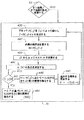
図1に、本発明の高レベルフロー図が示される。本発明において、元のビットマップファイル(O)が、アルゴリズムに入力される(ステップ10)。画像は、ビットマップ全体の大きさよりも小さいブロックで処理される(ステップ15)。好ましくは、これらのブロックは、大体、ビットマップの生成に用いられるハーフトーンスクリーンの「ハーフトーンセルの大きさ」に対応する。これらのブロックのドット面積率は、ローパスフィルタ、デシメーション及び補間処理を用いて推定される(ステップ15)。この処理の概要が、図2に示される。元のビットマップの予測されたドット面積率(Ain)は、ドットゲイン曲線(G)を用いて、目的のドット面積率(Aaim)に変換される。ドットゲイン曲線(G)は、所定の入力されたドット面積率に必要とされる利得の量を示す。このドットとゲインの関数(ドットゲイン関数)の例が、図3(a)及び図3(b)に示される(この関数は、異なる形態をもつことに注意して下さい)。ドットとゲインの関係は、2つの形態で説明される。図3aは、入力ドット面積率の関数としての出力ドット面積率を示し、図3bは、入力ドットの百分率の関数としての実際のドットゲインを示す。 A high level flow diagram of the present invention is shown in FIG. In the present invention, the original bitmap file (O) is input to the algorithm (step 10). The image is processed in blocks that are smaller than the overall bitmap size (step 15). Preferably, these blocks roughly correspond to the “halftone cell size” of the halftone screen used to generate the bitmap. The dot area ratio of these blocks is estimated using a low-pass filter, decimation and interpolation processing (step 15). An overview of this process is shown in FIG. The predicted dot area ratio (A in ) of the original bitmap is converted to the target dot area ratio (A aim ) using the dot gain curve (G). The dot gain curve (G) indicates the amount of gain required for a predetermined input dot area ratio. Examples of this dot and gain function (dot gain function) are shown in FIGS. 3 (a) and 3 (b) (note that this function has different forms). The relationship between dots and gain is described in two forms. FIG. 3a shows the output dot area ratio as a function of the input dot area ratio, and FIG. 3b shows the actual dot gain as a function of the percentage of input dots.
図1を参照すると、出力ビットマップ(B)は、入力ビットマップ(O)に等しくなるように初期化される(出力ビットマップは、入力ビットマップと同数の画素を有することに注意して下さい)。出力ビットマップ(B)は、15に定義されるように、L×Mのブロック(j=1,2,3...L,i=1,2,3...M)から成る。出力ビットマップ(B)は、Bにおける各々のブロックを処理することにより、繰り返して調整される。そのアルゴリズムは、ブロック変数i、j及びcを0に初期化することによって始まる(35)。ここで、i及びjは、現在のブロックの座標であり、cは、処理されたブロックの数を記録するカウンタである(ステップ35)。また、現在のブロック(すなわち、B(i,j))に関する量子化誤差に相当する変数εは、0に設定される(ステップ35)。 Referring to Figure 1, the output bitmap (B) is initialized to be equal to the input bitmap (O) (note that the output bitmap has the same number of pixels as the input bitmap) ). The output bitmap (B) is composed of L × M blocks (j = 1, 2, 3,... L, i = 1, 2, 3,... M) as defined in 15. The output bitmap (B) is adjusted iteratively by processing each block in B. The algorithm begins by initializing block variables i, j and c to 0 (35). Here, i and j are the coordinates of the current block, and c is a counter that records the number of processed blocks (step 35). Also, the variable ε corresponding to the quantization error relating to the current block (that is, B (i, j)) is set to 0 (step 35).
Bのブロック全体についての(i,jについての)2次元ループが、ステップ{40,45,46,47及び48}で確立される。この(i,jについての)2次元ループは、ステップ{50,55,60,65,70及び80}において実行される計算に対する指標i,jを制御する。2次元ループは、ステップ45に示されるように、Bにおける全てのブロックが処理される(すなわち、c=L×Mが成り立つ)まで実行される。
A two-dimensional loop (for i, j) for the entire block of B is established in steps {40, 45, 46, 47 and 48}. This two-dimensional loop (for i, j) controls the indices i, j for the calculations performed in steps {50, 55, 60, 65, 70 and 80}. The two-dimensional loop is executed until all blocks in B are processed (ie, c = L × M holds), as shown in
それ故、c≦L×Mが成り立つ間、Bにおける各々のブロックの処理は、以下の工程から成る。
(a)Bの(i,j)番目のブロックの面積カバー率が、Aaim(i,j)に近くなるように、Bの(i,j)番目のブロックに追加又は除去される画素数(N)を計算する(ステップ50)。Nの値は、以下の式(1)を用いて計算される。

![]()
(A) Number of pixels added to or removed from the (i, j) -th block of B so that the area coverage of the (i, j) -th block of B is close to A aim (i, j) (N) is calculated (step 50). The value of N is calculated using the following formula (1).
![]()
(b)量子化誤差(ε)を計算する(ステップ55)。NINT演算子が、Nを計算するために使用されたので、目標となるB(i,j)の面積カバー率(Aaim(i,j))と実際の面積カバー率との間に量子化によって誘発されるいくらかの誤差がある。この誤差は、以下の式(3)によって与えられる。
![]()
![]()
(c)量子化誤差(ε)を拡散する(ステップ60)。この量子化の目に見える効果を低減するために、誤差(ε)は、適切な誤差拡散スキームを用いて、Aaimの隣接する画素に拡散できる(ステップ60)。そのようなスキームの1つは、Floyd−Steinberg拡散重みを用いた誤差拡散である(それは、この例が、錯覚のために選択されることを認識するべきである。実際には、他の誤差拡散スキームが使用されてもよい)。 (C) The quantization error (ε) is diffused (step 60). To reduce the visible effect of this quantization, the error (ε) can be diffused to adjacent pixels in A aim using an appropriate error diffusion scheme (step 60). One such scheme is error diffusion using Floyd-Steinberg diffusion weights (it should be recognized that this example is chosen for the illusion. In practice, other errors A diffusion scheme may be used).
(d)オン状態の画素(以下、「オン画素」という。)、又はオフ状態の画素(以下、「オフ画素」という。)の数を変更する(ステップ65)(ステップ70,75,80)。現在のNの値が与えられると、オン画素又はオフ画素の数を追加、除去又は一定に保つ。2値画像におけるオン画素及びオフ画素は、オン画素=1及びオフ画素=0として定義される。B(i,j)における画素は、以下の法則に従う。
もし、N=0が成り立つなら、B(i,j)におけるオン画素又はオフ画素の数を同じにする(ステップ75)。
もし、N<0なら、ステップ70に与えられるスキームに従って、B(i,j)からN個のオン画素を除去する。
もし、N>0なら、80に与えられるスキームに従って、B(i,j)にN個のオン画素を追加する。
BにおけるL×M個のブロックの全てが処理される。
(D) The number of on-state pixels (hereinafter referred to as “on pixels”) or off-state pixels (hereinafter referred to as “off pixels”) is changed (step 65) (steps 70, 75, 80). . Given the current value of N, add, remove or keep the number of on or off pixels constant. The on pixel and off pixel in the binary image are defined as on pixel = 1 and off pixel = 0. The pixels in B (i, j) follow the following rules.
If N = 0 holds, the number of on or off pixels in B (i, j) is made the same (step 75).
If N <0, remove N ON pixels from B (i, j) according to the scheme given in
If N> 0, N ON pixels are added to B (i, j) according to the scheme given at 80.
All L × M blocks in B are processed.
(d)修正されたビットマップは、ディスクに記憶され、目的の印刷装置に送られる(ステップ85)。 (D) The corrected bitmap is stored on the disk and sent to the target printing device (step 85).
図2を参照すると、元のビットマップ(O)の局所的なドット面積率を推定する処理(ステップ15)は、Oの低域フィルタ処理とサブサンプリングから成る。まず、ダウンサンプリング係数Rが、ビットマップOのdpi及びlpiの比率に基づいて計算される(ステップ600)。(この関係は、ダウンサンプリングレート(R)を特定するために使用される処理の一例である。実際には、この値を設定するために、異なる基準が使用されてもよい。)。元のビットマップは、ダウンサンプリングレートの整数倍になるように、埋め込まれる(ステップ605)。局所的なドット面積率を生成するために使用される処理は、最終的なバイリニア補間の前に、ダウンバイツーデシメーションを使用する。各々のダウンバイツーデシメーションは、ダウンサンプリングレートが2であることに相当する。従って、Rにおけるダウンバイツーデシメーションlog2(R)が存在する。定義により、ダウンバイツーデシメーションの数は、整数である必要がある。従って、ダウンバイツーの数(n)は、以下の式(4)によって計算される(ステップ610)。
![]()
![]()
埋め込まれた元のオリジナルマップを考慮すると、出力された連続階調画像(Ain)は、Oに等しくなるように初期化される(ステップ615)。次に、ステップ625とステップ630で、範囲i=1,2,3…nに渡って、条件付きループが成立し、n回反復してAinを低域フィルタ処理し(ステップ635とステップ645)、サブサンプリング処理する(ステップ640とステップ650)。各々の繰り返しの間、低域フィルタ処理及びサブサンプリング処理は、別個に実行される。まず、Ainは、水平方向の平均カーネル(FH)で畳み込まれる(ステップ635)。次に、水平方向にフィルタ処理された画像は、水平方向に2回サブサンプリングされる。この処理は、垂直方向において、垂直方向の平均カーネル(Fv)(ステップ645)、及び2回のサブサンプリング処理(ステップ650)を用いて繰り返される(ステップ645)。Ainの低域フィルタ処理と2回のサブサンプリングとがn回なされた後、(ここで説明される処理が、Oの局所的なドット面積率を推定する処理のほんの一例であることに留意して下さい。本発明の精神において、ビットマップを、一組の推定の局所的ドット面積率に変換する他の処理が存在することが認識されるべきである。)
Considering the original original map embedded, the output continuous tone image (A in ) is initialized to be equal to O (step 615). Next, at
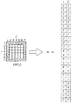
図4を参照し、NとBの所定のブロックとを考慮すると、B(i,j)にオン画素を追加するために使用されるスキームは、図5に示されるように、2値の構造要素(s)を用いて、B(i,j)を拡大することによって開始し、出力(D)の拡大版を生成する(ステップ330)(拡大は、丸付き+の記号で示されることに留意して下さい)。
次に(ステップ340)、B(i,j)に与えられる形状の「外側境界」(EB)が、以下の式(6)に与えられる関係を用いて決定される。
![]()
![]()
EBにおける「外側境界」要素の分離が、EBのサポートの領域内に含まれるオン画素を探索することによって実行される。これらの離れた位置は、現在のブロック(i,j)について、エッジマスク(m)と呼ばれるものに相当する(ステップ350)。それ故、mは、EB画像がオン状態である位置を含むk要素ベクトルである。それ故、エッジマスクをガイドとして使用すると、k個の外側境界画素の全ては、形状の画素数変更の候補である(ステップ360)。式(5)及び式(6)に形式化される処理は、図5aから図5cに示される。図5aを参照すると、B(i,j)は、対称的な構造要素(s)によって拡大され、Dを生成する。図5bを参照すると、外側境界(EB)は、DからB(i,j)を減じることによって生成される。図5cを参照すると、エッジマスク(m)は、EBにおけるオン画素の位置を記憶することによって生成される。 Separation of “outer boundary” elements in the EB is performed by searching for on-pixels contained within the region of EB support. These distant positions correspond to what is called an edge mask (m) for the current block (i, j) (step 350). Therefore, m is a k-element vector including the position where the EB image is in the on state. Therefore, using the edge mask as a guide, all of the k outer boundary pixels are candidates for shape pixel number change (step 360). The process formalized into equations (5) and (6) is shown in FIGS. 5a to 5c. Referring to FIG. 5a, B (i, j) is expanded by a symmetric structural element (s) to produce D. Referring to FIG. 5b, the outer boundary (EB) is generated by subtracting B (i, j) from D. Referring to FIG. 5c, the edge mask (m) is generated by storing the position of the on pixel in EB.
もし、kが、N以上なら(ステップ370)、エッジマスクmは、B(i,j)における形状を目標となる面積カバー率まで画素数変更するために十分な「外側境界」位置を含む。それ故、エッジマスクリストmに含まれる、B(i,j)における最初のN個の画素は、オン画素に変換される(ステップ380)。B(i,j)における画素が、オン画素に変換される順序は、順序付けられても無作為であってもよい。この順序は、「順序選択行列(P)」によって制御される(ステップ500)。順序選択行列(P)の一例は、図6に示される。この例において、ブロックB(i,j)は、7×7画素である。行列における数は、最低から最高まで、オン画素がB(i,j)に追加される順序に相当する。従って、もし、エッジマスクmが、Pにおける複数の位置に相当するB(i,j)における画素位置を含むなら、最も小さいPの値に相当するmにおける画素の位置は、最初にオンする。B(i,j)における続く画素は、mに記憶される各々の位置について、増加するP値に相当するパターンにおいてオンする(mにおける点に関連したP値は、調整を必要としないことに留意して下さい。)。例えば、所定の4要素mベクトルは、{1,9,3,8}のP値を有する画素位置を示してもよい。上述の論理を考慮すると、B(i,j)における画素は、m(1)、m(3)、m(4)、m(2)の順序でオンされる。 If k is greater than or equal to N (step 370), the edge mask m includes “outer boundary” positions sufficient to change the shape in B (i, j) to the target area coverage number of pixels. Therefore, the first N pixels in B (i, j) included in the edge mask list m are converted to on pixels (step 380). The order in which the pixels in B (i, j) are converted to on-pixels may be ordered or random. This order is controlled by the “order selection matrix (P)” (step 500). An example of the order selection matrix (P) is shown in FIG. In this example, the block B (i, j) is 7 × 7 pixels. The numbers in the matrix correspond to the order in which on pixels are added to B (i, j) from lowest to highest. Therefore, if the edge mask m includes a pixel position in B (i, j) corresponding to a plurality of positions in P, the position of the pixel in m corresponding to the smallest value of P is turned on first. Subsequent pixels in B (i, j) are turned on in a pattern corresponding to an increasing P value for each position stored in m (the P value associated with a point in m does not require adjustment). Please keep in mind.) For example, the predetermined 4-element m vector may indicate a pixel position having a P value of {1, 9, 3, 8}. Considering the above logic, the pixels in B (i, j) are turned on in the order of m (1), m (3), m (4), m (2).
もし、kがNより小さいなら(ステップ370)、エッジマスクmは、B(i,j)における形状を目標となる面積カバー率まで画素数変更するために十分な「外側境界」位置を含まない。それ故、エッジマスクリストmに含まれる、B(i,j)におけるk個の全ての画素が、オン画素に変換される(ステップ390)。目標となるドットの画素数変更が、B(i,j)におけるN個のオフ画素をオン画素に変換することを要するので、B(i,j)は、N個の全てのオフ画素がオン画素に変換されるまで、sによって反復して拡大され(ステップ330)、外側境界のマッピングに変換され(ステップ340)、エッジマスクに変換され(ステップ350)、埋め込まれる(ステップ380及びステップ390)。各々の反復の間、次の反復に必要とされるオン画素の数は、現在の反復において生成されるオン画素の数によって、Nを調整することにより更新される(すなわち、N=N−k)(ステップ395)。
If k is less than N (step 370), the edge mask m does not contain enough “outer boundary” positions to change the number of pixels from B (i, j) to the target area coverage. . Therefore, all k pixels in B (i, j) included in the edge mask list m are converted to on pixels (step 390). Since changing the number of pixels of the target dot requires converting N off pixels in B (i, j) to on pixels, B (i, j) is turned on for all N off pixels. It is iteratively enlarged by s until it is converted to a pixel (step 330), converted to an outer boundary mapping (step 340), converted to an edge mask (step 350), and embedded (
図1を参照すると、B(i,j)からオン画素を除去する処理(70)が、図7に示される。図7に示されるように、所定のNとBの所定のブロックに対し、B(i,j)からオン画素を除去するために使用されるスキームが、2値の構造要素(s)を用いてB(i,j)を縮小することによって始まり、出力(E)が縮小版を生成する(ステップ430)(縮小は、記号Θで示されることに留意して下さい)。
次に(ステップ440)、B(i,j)に与えられる形状の「内側境界」(IB)が、以下の式(8)に与えられる関係を用いて決定される。
![]()
![]()
IBにおける「内側境界」の分離が、IBのサポートの領域内に含まれるオン画素を探し出すことによって実行される。これらの離れた位置は、現在のブロック(i,j)に対して、「エッジマスク」(m)と呼ばれるものに相当する(ステップ450)。それ故、mは、IB画像がオン状態である位置を含むk要素ベクトルである。それ故、エッジマスクをガイドとして用いると、k個の「内側境界」画素の全てが、形状の画素数変更の候補である。式(7)や式(8)に形式化された方法は、図8に示される。図8を参照すると、元の形状が、対称的な構造要素(s)によって縮小され、E(i,j)を生成する。図8bを参照すると、内側境界(IB)が、B(i,j)からE(i,j)を減じることによって生成される。図8cを参照すると、エッジマスク(m)は、IBにおけるオン画素の位置を記憶することによって生成される。 Separation of “inner boundaries” in the IB is performed by finding on-pixels that fall within the IB support area. These remote locations correspond to what is called an “edge mask” (m) for the current block (i, j) (step 450). Therefore, m is a k-element vector including the position where the IB image is in the on state. Therefore, when the edge mask is used as a guide, all k “inner boundary” pixels are candidates for shape pixel number change. The method formalized in Equation (7) or Equation (8) is shown in FIG. Referring to FIG. 8, the original shape is reduced by a symmetric structural element (s) to produce E (i, j). Referring to FIG. 8b, the inner boundary (IB) is generated by subtracting E (i, j) from B (i, j). Referring to FIG. 8c, the edge mask (m) is generated by storing the position of the on pixel in the IB.
図7を参照すると、もし、kが|N|以上なら、エッジマスクmは、B(i,j)における形状を、目標となる面積カバー率まで画素数変更するのに十分な「内側境界」の位置を含む。それ故、エッジマスクリストmに含まれるB(i,j)における第1の|N|画素が、オフ画素に変換される(ステプ480)。B(i,j)における画素が、オフ画素に変換される順番は、順序付けられていても無作為であってもよい。この順番は、「順序選択行列」(P)によって制御される(ステップ500)。順序選択行列(P)の一例が、図6に示される。この例において、ブロックB(i,j)は、10×10の画素である。行列における数は、最低値から最高値まで、オン画素が、B(i,j)から除去される順序に相当する。従って、もし、エッジマスクmが、Pにおける複数の位置に対応するB(i,j)における画素の位置を含むなら、まず、mにおける、最も小さいPの値に対応する画素の位置がオフされる。B(i,j)におけるそれに続く画素は、mに記憶された各々の位置について、増加するPの値に対応するパターンにおいてオフされる(mにおける点と関連するPの値は、調整する必要がないことに留意して下さい。)。例えば、所定の4要素のmベクトルは、{1,9,3,8}のPの値をもつ画素の位置を示してもよい。上述の論理を考慮すると、B(i,j)における画素は、m(1)、m(3)、m(4)、m(2)の順序でオフされる。 Referring to FIG. 7, if k is greater than or equal to | N |, the edge mask m is an “inner boundary” sufficient to change the shape of B (i, j) to the target area coverage ratio and the number of pixels Including the location. Therefore, the first | N | pixel in B (i, j) included in the edge mask list m is converted to an off pixel (step 480). The order in which the pixels in B (i, j) are converted to off pixels may be ordered or random. This order is controlled by the “order selection matrix” (P) (step 500). An example of the order selection matrix (P) is shown in FIG. In this example, the block B (i, j) is 10 × 10 pixels. The numbers in the matrix correspond to the order in which on-pixels are removed from B (i, j) from lowest to highest. Therefore, if the edge mask m includes pixel positions in B (i, j) corresponding to a plurality of positions in P, first, the position of the pixel corresponding to the smallest value of P in m is turned off. The Subsequent pixels in B (i, j) are turned off in a pattern corresponding to increasing values of P for each position stored in m (the value of P associated with the point in m needs to be adjusted) Please note that there is no.) For example, the predetermined four-element m-vector may indicate the position of a pixel having a P value of {1, 9, 3, 8}. Considering the above logic, the pixels in B (i, j) are turned off in the order of m (1), m (3), m (4), m (2).
もし、kが|N|より小さいなら(ステップ470)、エッジマスクmは、B(i,j)における形状を目標となる面積カバー率まで画素数変更するために十分な「内側境界」を含まない。それ故、エッジマスクリストmに含まれる、B(i,j)におけるk個の全ての画素が、オフ画素に変換される(ステップ490)。目標となるドットの画素数変更が、B(i,j)における|N|個のオン画素をオフ画素に変換することを要するので、B(i,j)は、|N|個の全てのオン画素がオフ画素に変換されるまで、sによって反復して収縮され(ステップ430)、内側境界のマッピングに変換され(ステップ440)、エッジマスクに変換され(ステップ450)、埋め込まれる(ステップ480及びステップ490)。各々の反復の間、次の反復に必要とされるオフ画素の数は、現在の反復において生成されるオフ画素の数によって、Nを調整することにより更新される(すなわち、N=−(|N|−k))(ステップ495)。 If k is smaller than | N | (step 470), the edge mask m includes an “inner boundary” sufficient to change the shape in B (i, j) to the target area coverage number of pixels. Absent. Therefore, all k pixels in B (i, j) included in the edge mask list m are converted to off pixels (step 490). Since changing the number of pixels of the target dot requires converting | N | ON pixels in B (i, j) to OFF pixels, B (i, j) is all | N | It is iteratively shrunk by s until the on pixel is converted to an off pixel (step 430), converted to an inner boundary mapping (step 440), converted to an edge mask (step 450), and embedded (step 480). And step 490). During each iteration, the number of off pixels required for the next iteration is updated by adjusting N by the number of off pixels generated in the current iteration (ie, N = − (| N | -k)) (step 495).
本発明の用途は、RIP−once−output−many(ROOM)システムである。これらは、印刷の準備ができたビットマップファイルを取り込み、デジタル校正システムにおいて使用できる調整されたビットマップファイルを生成するデジタル校正装置等のシステムである。このシナリオにおいて、印刷の準備ができたビットマップファイルは、所定のデジタル校正システムで印刷されるとき、結果として得られる校正が補正色及び色調特性を有するように、調整される。 The application of the present invention is a RIP-once-output-many (ROOM) system. These are systems such as digital proofing devices that take a bitmap file ready for printing and generate an adjusted bitmap file that can be used in a digital proofing system. In this scenario, a bitmap file ready for printing is adjusted so that the resulting proof has the correct color and tone characteristics when printed with a predetermined digital proofing system.
10,15,20,25,30,35,40,45,46,47,48,50,55,60,65,70,75,80,85 ドット画素数変更アルゴリズムの高レベル処理を構成するステップ
10, 15, 20, 25, 30, 35, 40, 45, 46, 47, 48, 50, 55, 60, 65, 70, 75, 80, 85 Steps for configuring the high-level processing of the dot pixel number changing algorithm
Claims (3)
中間調ビットマップ原画像を提供する提供ステップと、
一組の副画像ブロックにおける前記中間調ビットマップ原画像のドット面積率を推定する推定ステップと、
前記中間調ビットマップ原画像における各々の前記副画像ブロックについて、所定の色校正関数に基づき、目標となるドット面積率を計算する第1計算ステップと、
前記中間調ビットマップ原画像における各々の前記副画像ブロックについて、目標となる前記ドット面積率を有する修正された中間調ビットマップ画像を生成するために、N(ここで、Nは、目標となる前記ドット面積率と推定された前記ドット面積率との間の差の関数によって決定される整数である)で示される、オン状態又はオフ状態に変換される中間調ビットマップ画像の画素数を計算する第2計算ステップと、
前記中間調ビットマップ原画像における各々の前記副画像ブロックについて、前記中間調ビットマップ原画像における|N|(ここで、|N|は、Nの値の絶対値を表す)個の画素を、目標となる前記ドット面積率が、推定された前記ドット面積率よりも大きいことにより、Nの値が正である時には、オフ状態からオン状態に変換すると共に、目標となる前記ドット面積率が、推定された前記ドット面積率よりも小さいことにより、Nの値が負である時には、オン状態からオフ状態に変換する変換ステップとを備え、
前記中間長ビットマップ原画像の所定ブロックにおける|N|個の画素を、色校正された前記中間調ビットマップ画像の対応するブロックにおけるオン状態又はオフ状態に変換する変換ステップが、
所定ブロックに含まれる前記中間調ビットマップ画像の境界画素のエッジマスクを計算する計算ステップと、
その値がkで示される、現在のブロックの境界画素の数を計数する計数ステップと、
もしkが|N|より大きければ、エッジマスク内に存在する|N|個のオン又はオフの画素を、夫々、オフ又はオンの画素に選択的に変換し、もしkが|N|より小さければ、エッジマスク内に存在する全てのオン又はオフの画素を、夫々、オフ又はオンの画素に変換する変換ステップと、
Nとkの現在値に基づいて修正されたN値を生成することによって、現在のブロックにおいて変換すべき画素の数を更新する更新ステップと、
Nの修正値が現在のブロックに対して零となるまで、前記計算ステップ、前記計数ステップ、前記変換ステップと前記更新ステップを再帰的に繰返す繰返しステップと
を含み、
目標となる前記ドット面積率が、前記前記中間調ビットマップ原画像の前記ドット面積率よりも大きいか小さいかに応じて、前記境界画素が、外側境界画素又は内側境界画素である画像校正方法。An image calibration method for calibrating a halftone bitmap original image with a predetermined color calibration function to generate a color calibrated halftone bitmap image,
Providing a halftone bitmap original image;
An estimation step of estimating a dot area ratio of the halftone bitmap original image in a set of sub-image blocks;
A first calculation step of calculating a target dot area ratio based on a predetermined color calibration function for each of the sub-image blocks in the halftone bitmap original image;
For each sub-image block in the halftone bitmap original image, N (where N is the target) to generate a modified halftone bitmap image having the target dot area ratio calculating the number of pixels halftone bitmap image represented by an a) integer, Ru is converted into an on state or an off state determined by the function of the difference between the dot area rate and the estimated the dot area ratio A second calculation step,
For each sub-image block in the halftone bitmap original image, | N | (where | N | represents the absolute value of the value of N) pixels in the halftone bitmap original image, When the target dot area ratio is larger than the estimated dot area ratio , when the value of N is positive, the target dot area ratio is changed from an off state to an on state. A conversion step of converting from an on state to an off state when the value of N is negative by being smaller than the estimated dot area ratio ,
A conversion step of converting | N | pixels in a predetermined block of the intermediate-length bitmap original image into an ON state or an OFF state in a corresponding block of the halftone bitmap image subjected to color calibration,
A calculation step of calculating an edge mask of a boundary pixel of the halftone bitmap image included in a predetermined block;
A counting step for counting the number of boundary pixels of the current block, the value of which is denoted k;
If k is greater than | N |, selectively convert | N | on or off pixels present in the edge mask to off or on pixels, respectively, if k is less than | N | For example, a conversion step of converting all on or off pixels present in the edge mask to off or on pixels, respectively;
An update step of updating the number of pixels to be transformed in the current block by generating a modified N value based on the current values of N and k;
Recursively repeating the calculating step, the counting step, the converting step and the updating step until a correction value of N becomes zero for the current block;
An image calibration method in which the boundary pixel is an outer boundary pixel or an inner boundary pixel depending on whether the target dot area ratio is larger or smaller than the dot area ratio of the halftone bitmap original image.
色校正された前記中間調ビットマップ画像の所定の前記副画像ブロックと、前記中間調ビットマップ原画像の対応するブロックについて、目標となる前記ドット面積率と推定された前記ドット面積率との差を計算する計算ステップと、
現在の前記中間調ビットマップ原画像において、前記差を、前記中間調ビットマップ画像の単一の画素のドット面積率によって除算し、その除算の結果を四捨五入して、最も近い整数値にすることによって、前記差を、修正すべき前記中間調ビットマップ画像の画素数に変換する変換ステップと
を備える請求項1に記載の画像校正方法。The second calculation step includes:
The difference between the target dot area rate and the estimated dot area rate for the predetermined sub-image block of the halftone bitmap image subjected to color calibration and the corresponding block of the halftone bitmap original image A calculation step for calculating
In the current halftone bitmap original image, the difference is divided by the dot area ratio of a single pixel of the halftone bitmap image, and the result of the division is rounded to the nearest integer value. The image calibration method according to claim 1, further comprising: a conversion step of converting the difference into the number of pixels of the halftone bitmap image to be corrected.
Applications Claiming Priority (1)
| Application Number | Priority Date | Filing Date | Title |
|---|---|---|---|
| US10/154,546 US7116447B2 (en) | 2002-05-24 | 2002-05-24 | Halftone dot-growth technique using a dot edge-detection scheme |
Publications (2)
| Publication Number | Publication Date |
|---|---|
| JP2004040781A JP2004040781A (en) | 2004-02-05 |
| JP4386674B2 true JP4386674B2 (en) | 2009-12-16 |
Family
ID=29400559
Family Applications (1)
| Application Number | Title | Priority Date | Filing Date |
|---|---|---|---|
| JP2003147976A Expired - Fee Related JP4386674B2 (en) | 2002-05-24 | 2003-05-26 | A technique for changing the number of halftone dots using a dot edge detection scheme |
Country Status (4)
| Country | Link |
|---|---|
| US (1) | US7116447B2 (en) |
| EP (1) | EP1365574B1 (en) |
| JP (1) | JP4386674B2 (en) |
| DE (1) | DE60333417D1 (en) |
Families Citing this family (42)
| Publication number | Priority date | Publication date | Assignee | Title |
|---|---|---|---|---|
| US6297889B1 (en) * | 1998-12-22 | 2001-10-02 | Xerox Corporation | Logic-based image processing method |
| DE10143942A1 (en) * | 2001-09-07 | 2003-03-27 | Wifag Maschf | Test equipment and methods for controlling offset and digital printing |
| US7365881B2 (en) * | 2002-08-19 | 2008-04-29 | Eastman Kodak Company | Halftone dot-growth technique based on morphological filtering |
| US6893105B2 (en) * | 2003-01-31 | 2005-05-17 | Eastman Kodak Company | Method for printing an image from a halftone binary bitmap using multiple exposures |
| US7710597B2 (en) * | 2003-07-01 | 2010-05-04 | Eastman Kodak Company | Modified Neugebauer model for halftone imaging systems |
| EP1596575A3 (en) * | 2003-10-23 | 2010-03-10 | Agfa Graphics N.V. | Method for making a dot for dot proof |
| JP2005252893A (en) * | 2004-03-05 | 2005-09-15 | Fuji Photo Film Co Ltd | Threshold matrix |
| JP2005252888A (en) * | 2004-03-05 | 2005-09-15 | Fuji Photo Film Co Ltd | Method for generating threshold matrix and threshold matrix thereof, and reproducing method of color image |
| JP2005286999A (en) * | 2004-03-05 | 2005-10-13 | Fuji Photo Film Co Ltd | Allocation method of threshold matrix |
| JP4143560B2 (en) * | 2004-03-05 | 2008-09-03 | 富士フイルム株式会社 | Method and apparatus for creating threshold matrix |
| KR100611981B1 (en) * | 2004-05-01 | 2006-08-11 | 삼성전자주식회사 | Method and apparatus for halftoning digital images |
| US20050259280A1 (en) * | 2004-05-05 | 2005-11-24 | Kodak Polychrome Graphics, Llc | Color management of halftone prints |
| WO2005109849A1 (en) * | 2004-05-05 | 2005-11-17 | Kodak Polychrome Graphics, Llc | Halftone proofing with inkjet printers |
| JP2006033064A (en) * | 2004-07-12 | 2006-02-02 | Konica Minolta Medical & Graphic Inc | Image forming method, and image forming apparatus |
| US7500218B2 (en) * | 2004-08-17 | 2009-03-03 | Asml Netherlands B.V. | Lithographic apparatus, method, and computer program product for generating a mask pattern and device manufacturing method using same |
| US8432582B2 (en) * | 2004-08-20 | 2013-04-30 | Xerox Corporation | Uniformity compensation in halftoned images |
| US7460276B2 (en) * | 2004-12-17 | 2008-12-02 | Xerox Corporation | Systems and methods for rank-order error diffusion image processing |
| US7440139B2 (en) * | 2005-01-13 | 2008-10-21 | Xerox Corporation | Systems and methods for controlling a tone reproduction curve using error diffusion |
| JP4241632B2 (en) * | 2005-01-25 | 2009-03-18 | 富士フイルム株式会社 | Color plate creation threshold value matrix creation method, color image reproduction method, color image separation creation device, and threshold matrix |
| US7336820B2 (en) * | 2005-02-04 | 2008-02-26 | Kabushiki Kaisha Toshiba | Method and apparatus for rapid shading in a raster image processor |
| US7973972B2 (en) * | 2005-02-22 | 2011-07-05 | Fuji Xerox Co., Ltd. | Halftone dot formation method and apparatus, and image forming apparatus |
| US8049929B2 (en) * | 2005-09-02 | 2011-11-01 | Xerox Corporation | Color management of halftoned images |
| CN101473656B (en) | 2006-06-29 | 2011-09-14 | 汤姆森许可贸易公司 | Adaptive filtering based on pixel |
| JP5330246B2 (en) | 2006-09-29 | 2013-10-30 | トムソン ライセンシング | Automatic parameter estimation for adaptive pixel-based filtering |
| JP4851388B2 (en) * | 2007-05-16 | 2012-01-11 | 浜松ホトニクス株式会社 | Imaging device |
| KR101330665B1 (en) * | 2008-02-29 | 2013-11-15 | 삼성전자주식회사 | Apparatus and method for revising halftoning image, image forming device using the same |
| US20090315939A1 (en) * | 2008-06-24 | 2009-12-24 | Xerox Corporation | System And Method For Defective Inkjet Correction Using Edge Information In An Image |
| US8399177B2 (en) * | 2008-12-08 | 2013-03-19 | Eastman Kodak Company | Enhanced relief printing plate |
| KR101614460B1 (en) * | 2009-05-20 | 2016-04-21 | 마퍼 리쏘그라피 아이피 비.브이. | Pattern data conversion for lithography system |
| TWI547766B (en) * | 2009-05-20 | 2016-09-01 | 瑪波微影Ip公司 | Multi-tone rasterization |
| EP3144955A1 (en) | 2009-05-20 | 2017-03-22 | Mapper Lithography IP B.V. | Method for exposing a wafer |
| US8678533B2 (en) | 2010-06-14 | 2014-03-25 | Xerox Corporation | System and method to compensate for defective inkjets in an inkjet imaging apparatus |
| US8764151B2 (en) | 2010-06-21 | 2014-07-01 | Xerox Corporation | System and method for preserving edges while enabling inkjet correction within an interior of an image |
| DE102010034068A1 (en) * | 2010-08-12 | 2012-02-16 | Rohde & Schwarz Gmbh & Co. Kg | Method and device for preventing signal edge loss |
| US8985723B2 (en) | 2012-04-20 | 2015-03-24 | Xerox Corporation | System and method of compensating for defective inkjets |
| US8714692B1 (en) | 2012-12-04 | 2014-05-06 | Xerox Corporation | System and method of compensating for defective inkjets with context dependent image data |
| US10119111B2 (en) * | 2014-01-14 | 2018-11-06 | SCREEN Holdings Co., Ltd. | Cell colony area specifying apparatus, cell colony area specifying method, and recording medium |
| US9704228B1 (en) * | 2014-08-26 | 2017-07-11 | Marvell International Ltd. | System and method for fractional pixel dilation and erosion |
| CN109727232B (en) * | 2018-12-18 | 2023-03-31 | 上海出版印刷高等专科学校 | Method and apparatus for detecting dot area ratio of printing plate |
| CN109712095B (en) * | 2018-12-26 | 2023-05-12 | 西安工程大学 | Face beautifying method with rapid edge preservation |
| US10855881B1 (en) | 2019-12-18 | 2020-12-01 | Ricoh Company, Ltd. | Vectorized multi-level halftoning using ternary logic |
| EP4113964A1 (en) * | 2021-06-30 | 2023-01-04 | Akzenta Paneele + Profile GmbH | Method for colour correction of digital printing |
Family Cites Families (12)
| Publication number | Priority date | Publication date | Assignee | Title |
|---|---|---|---|---|
| US4945422A (en) | 1990-01-02 | 1990-07-31 | Eastman Kodak Company | False density contour suppression using stored random probabilities to form print/no-print decisions |
| US5208871A (en) * | 1990-10-19 | 1993-05-04 | Xerox Corporation | Pixel quantization with adaptive error diffusion |
| US5250934A (en) * | 1990-12-31 | 1993-10-05 | Xerox Corporation | Method and apparatus for thinning printed images |
| US5293539A (en) * | 1991-10-25 | 1994-03-08 | Eastman Kodak Company | Method and apparatus for calibrating tone reproduction in a proofing system |
| US5255085A (en) * | 1991-10-25 | 1993-10-19 | Eastman Kodak Company | Adaptive technique for providing accurate tone reproduction control in an imaging system |
| US5258854A (en) * | 1991-12-06 | 1993-11-02 | Xerox Corporation | Converting between write-white, write-black and neutral bitmaps |
| US5483351A (en) * | 1992-09-25 | 1996-01-09 | Xerox Corporation | Dilation of images without resolution conversion to compensate for printer characteristics |
| US5680485A (en) * | 1994-12-19 | 1997-10-21 | Xerox Corporation | Method and apparatus employing erosion-based filter pairs for image mapping |
| JP2889177B2 (en) | 1995-03-22 | 1999-05-10 | アグフア−ゲヴエルト・ナームローゼ・フエンノートシヤツプ | Method for generating a halftone image from a contone image |
| US5680458A (en) * | 1995-11-14 | 1997-10-21 | Microsoft Corporation | Root key compromise recovery |
| DE19826986C2 (en) | 1998-06-18 | 2003-03-27 | Heidelberger Druckmasch Ag | Calibration procedures for image recorders |
| US6115140A (en) * | 1998-07-28 | 2000-09-05 | Shira Computers Ltd. | Method and system for half tone color conversion |
-
2002
- 2002-05-24 US US10/154,546 patent/US7116447B2/en active Active
-
2003
- 2003-05-12 EP EP03076416A patent/EP1365574B1/en not_active Expired - Fee Related
- 2003-05-12 DE DE60333417T patent/DE60333417D1/en not_active Expired - Lifetime
- 2003-05-26 JP JP2003147976A patent/JP4386674B2/en not_active Expired - Fee Related
Also Published As
| Publication number | Publication date |
|---|---|
| EP1365574A2 (en) | 2003-11-26 |
| US20030218780A1 (en) | 2003-11-27 |
| EP1365574B1 (en) | 2010-07-21 |
| EP1365574A3 (en) | 2005-03-02 |
| US7116447B2 (en) | 2006-10-03 |
| JP2004040781A (en) | 2004-02-05 |
| DE60333417D1 (en) | 2010-09-02 |
Similar Documents
| Publication | Publication Date | Title |
|---|---|---|
| JP4386674B2 (en) | A technique for changing the number of halftone dots using a dot edge detection scheme | |
| EP1392048B1 (en) | Halftone dot-growth technique based on morphological filtering | |
| EP0749231B1 (en) | Method and apparatus for halftone rendering of a gray scale image using a blue noise mask | |
| US7440139B2 (en) | Systems and methods for controlling a tone reproduction curve using error diffusion | |
| US5477305A (en) | Method and apparatus for halftone rendering of a gray scale image using a blue noise mask | |
| US5268774A (en) | Halftoning with enhanced dynamic range and edge enhanced error diffusion | |
| JP4173154B2 (en) | Image processing method, image processing apparatus, image forming apparatus, computer program, and recording medium | |
| US5317653A (en) | Method for quantization gray level pixel data with application of under compensated error diffusion | |
| US8149464B2 (en) | Clustered dot-screen design method, a device to perform the clustered dot-screen design method based on human vision and printer model characteristics, and an image-forming apparatus to output binary images on a designed screen | |
| JPH03193472A (en) | Highly definite image generating system of image processor | |
| US6297889B1 (en) | Logic-based image processing method | |
| EP0817466B1 (en) | Edge enhanced error diffusion | |
| US6025930A (en) | Multicell clustered mask with blue noise adjustments | |
| US7009737B2 (en) | Image processing method and apparatus | |
| US20060238784A1 (en) | Image processing apparatus using multi-level halftoning and method thereof | |
| US6356360B1 (en) | Apparatus and method for rendering halftone dot structures using grey level dots | |
| EP2187616A1 (en) | Image data processing for printing | |
| CA2231816C (en) | Method and apparatus for halftone rendering of a gray scale image using a blue noise mask | |
| JPH11112815A (en) | Device for extending resolution and its method |
Legal Events
| Date | Code | Title | Description |
|---|---|---|---|
| A621 | Written request for application examination |
Free format text: JAPANESE INTERMEDIATE CODE: A621 Effective date: 20060302 |
|
| RD03 | Notification of appointment of power of attorney |
Free format text: JAPANESE INTERMEDIATE CODE: A7423 Effective date: 20080131 |
|
| A131 | Notification of reasons for refusal |
Free format text: JAPANESE INTERMEDIATE CODE: A131 Effective date: 20080520 |
|
| A601 | Written request for extension of time |
Free format text: JAPANESE INTERMEDIATE CODE: A601 Effective date: 20080820 |
|
| A602 | Written permission of extension of time |
Free format text: JAPANESE INTERMEDIATE CODE: A602 Effective date: 20080825 |
|
| A521 | Written amendment |
Free format text: JAPANESE INTERMEDIATE CODE: A523 Effective date: 20081007 |
|
| A131 | Notification of reasons for refusal |
Free format text: JAPANESE INTERMEDIATE CODE: A131 Effective date: 20090120 |
|
| A521 | Written amendment |
Free format text: JAPANESE INTERMEDIATE CODE: A523 Effective date: 20090416 |
|
| A131 | Notification of reasons for refusal |
Free format text: JAPANESE INTERMEDIATE CODE: A131 Effective date: 20090519 |
|
| A521 | Written amendment |
Free format text: JAPANESE INTERMEDIATE CODE: A523 Effective date: 20090811 |
|
| TRDD | Decision of grant or rejection written | ||
| A01 | Written decision to grant a patent or to grant a registration (utility model) |
Free format text: JAPANESE INTERMEDIATE CODE: A01 Effective date: 20090901 |
|
| A01 | Written decision to grant a patent or to grant a registration (utility model) |
Free format text: JAPANESE INTERMEDIATE CODE: A01 |
|
| A61 | First payment of annual fees (during grant procedure) |
Free format text: JAPANESE INTERMEDIATE CODE: A61 Effective date: 20090929 |
|
| R150 | Certificate of patent or registration of utility model |
Free format text: JAPANESE INTERMEDIATE CODE: R150 |
|
| FPAY | Renewal fee payment (event date is renewal date of database) |
Free format text: PAYMENT UNTIL: 20121009 Year of fee payment: 3 |
|
| FPAY | Renewal fee payment (event date is renewal date of database) |
Free format text: PAYMENT UNTIL: 20121009 Year of fee payment: 3 |
|
| FPAY | Renewal fee payment (event date is renewal date of database) |
Free format text: PAYMENT UNTIL: 20131009 Year of fee payment: 4 |
|
| R250 | Receipt of annual fees |
Free format text: JAPANESE INTERMEDIATE CODE: R250 |
|
| R250 | Receipt of annual fees |
Free format text: JAPANESE INTERMEDIATE CODE: R250 |
|
| R250 | Receipt of annual fees |
Free format text: JAPANESE INTERMEDIATE CODE: R250 |
|
| R250 | Receipt of annual fees |
Free format text: JAPANESE INTERMEDIATE CODE: R250 |
|
| R250 | Receipt of annual fees |
Free format text: JAPANESE INTERMEDIATE CODE: R250 |
|
| LAPS | Cancellation because of no payment of annual fees |