JP4386130B2 - Mold for press machine and open drawing method - Google Patents
Mold for press machine and open drawing method Download PDFInfo
- Publication number
- JP4386130B2 JP4386130B2 JP2007310965A JP2007310965A JP4386130B2 JP 4386130 B2 JP4386130 B2 JP 4386130B2 JP 2007310965 A JP2007310965 A JP 2007310965A JP 2007310965 A JP2007310965 A JP 2007310965A JP 4386130 B2 JP4386130 B2 JP 4386130B2
- Authority
- JP
- Japan
- Prior art keywords
- punch
- die
- recess
- open
- blank holder
- Prior art date
- Legal status (The legal status is an assumption and is not a legal conclusion. Google has not performed a legal analysis and makes no representation as to the accuracy of the status listed.)
- Expired - Fee Related
Links
Images


Classifications
-
- B—PERFORMING OPERATIONS; TRANSPORTING
- B21—MECHANICAL METAL-WORKING WITHOUT ESSENTIALLY REMOVING MATERIAL; PUNCHING METAL
- B21D—WORKING OR PROCESSING OF SHEET METAL OR METAL TUBES, RODS OR PROFILES WITHOUT ESSENTIALLY REMOVING MATERIAL; PUNCHING METAL
- B21D22/00—Shaping without cutting, by stamping, spinning, or deep-drawing
- B21D22/02—Stamping using rigid devices or tools
- B21D22/06—Stamping using rigid devices or tools having relatively-movable die parts
-
- B—PERFORMING OPERATIONS; TRANSPORTING
- B21—MECHANICAL METAL-WORKING WITHOUT ESSENTIALLY REMOVING MATERIAL; PUNCHING METAL
- B21D—WORKING OR PROCESSING OF SHEET METAL OR METAL TUBES, RODS OR PROFILES WITHOUT ESSENTIALLY REMOVING MATERIAL; PUNCHING METAL
- B21D22/00—Shaping without cutting, by stamping, spinning, or deep-drawing
- B21D22/20—Deep-drawing
- B21D22/22—Deep-drawing with devices for holding the edge of the blanks
-
- B—PERFORMING OPERATIONS; TRANSPORTING
- B21—MECHANICAL METAL-WORKING WITHOUT ESSENTIALLY REMOVING MATERIAL; PUNCHING METAL
- B21D—WORKING OR PROCESSING OF SHEET METAL OR METAL TUBES, RODS OR PROFILES WITHOUT ESSENTIALLY REMOVING MATERIAL; PUNCHING METAL
- B21D24/00—Special deep-drawing arrangements in, or in connection with, presses
- B21D24/04—Blank holders; Mounting means therefor
Landscapes
- Engineering & Computer Science (AREA)
- Mechanical Engineering (AREA)
- Shaping Metal By Deep-Drawing, Or The Like (AREA)
Description
本発明は、プレス装置用金型および該プレス装置用金型による開放絞り成形方法に関する。 The present invention relates to a mold for a press apparatus and an open drawing method using the mold for a press apparatus.
従来、プレス成形を行う際に、製品形状に形成したキャビティのコーナー部において、該コーナー部よりも所定間隔外側に緩やかな凹または凸形状部を設けることにより、材料流入に伴う圧縮応力に耐えうるようにして、製品にしわや割れが発生することを防止する技術が知られており、以下の特許文献1等に開示されている。 Conventionally, when press molding is performed, at a corner portion of a cavity formed in a product shape, a gentle concave or convex shape portion is provided outside the corner portion by a predetermined interval, so that it can withstand compressive stress due to material inflow. In this way, a technique for preventing wrinkles and cracks from occurring in a product is known, and is disclosed in Patent Document 1 below.
しかしながら、特許文献1に示される従来技術は、開放絞りを行う場合における開放側からの材料流入防止対策としては適用することができないため、開放絞りを行う場合には他の対策を講じる必要があった。 However, since the prior art disclosed in Patent Document 1 cannot be applied as a material inflow prevention measure from the open side when performing an open aperture, it is necessary to take other measures when performing an open aperture. It was.
また、従来開放絞り成形を行う場合において、製品にしわや割れが発生することを防止する技術としては、以下の特許文献2等に開示されている。
この特許文献2に示される従来技術では、ワークをダイ形状に対応した曲げ状態に保って開放絞り成形をすることにより、製品にしわや割れが発生することを防止するようにしている。しかしながら、特許文献2に示される従来技術は、開放側からの材料素材の流入量を積極的に調整することを目的とはしておらず、開放側からの材料素材の流入量過多に起因するしわや割れを防止することが困難であった。
Further, as a technique for preventing wrinkles and cracks from occurring in the conventional open drawing, the following
In the prior art disclosed in
ここで、従来技術の実施の形態を説明する。
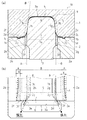
図5は従来のプレス装置用金型の全体構成を示す斜視図、図6(a)は従来の開放絞り成形方法によるプレス成形の状況(準備段階)を示す正面側断面図、図6(b)は同じく部分平面図、図7(a)は従来の開放絞り成形方法によるプレス成形の状況(成形途中)を示す正面側断面図、図7(b)は同じく部分平面図、図8(a)は従来の開放絞り成形方法によるプレス成形の状況(成形完了時)を示す正面側断面図、図8(b)は同じく部分平面図である。
Here, an embodiment of the prior art will be described.
FIG. 5 is a perspective view showing the overall configuration of a conventional press device mold, FIG. 6 (a) is a front cross-sectional view showing the state (preparation stage) of press forming by a conventional open drawing method, and FIG. 6 (b). ) Is a partial plan view, FIG. 7A is a front sectional view showing the state of press forming by the conventional open drawing method (in the middle of forming), FIG. 7B is a partial plan view, and FIG. ) Is a front sectional view showing the state of press forming by the conventional open drawing method (when forming is completed), and FIG. 8B is a partial plan view.
以下に、従来のプレス装置用金型30および該プレス装置用金型30による開放絞り成形方法について説明をする。
尚、説明の便宜上、図5中の基準座標軸に示す矢印Xの方向(製品の長さ方向)を前方、矢印Yの方向(製品の幅方向)を右方、矢印Zの方向(製品の高さ方向)を上方として、以下の説明を行う。
Below, the
For convenience of explanation, the direction of the arrow X (product length direction) shown on the reference coordinate axis in FIG. 5 is the front, the direction of the arrow Y (product width direction) is the right, and the direction of the arrow Z (product height) The following description will be given with the (direction) as the upper side.
図5に示す如く、従来のプレス装置用金型30は、上型たるダイ31と、ブランクホルダー32と、下型たるポンチ33等により構成される。
ダイ31の下面側には、底部31fおよび左右の側面部31g・31hからなり下方および前後方向に開放される凹部31aを形成している。また、ダイ31の下面側には、凹部31aを挟んでクッション面31b・31cを左右に形成している。さらに、クッション面31b・31cには、該クッション面31b・31cの前後方向の全長に渉って、ビード31d・31eを下方に突出して形成している。
As shown in FIG. 5, a conventional press device die 30 includes an
On the lower surface side of the
ブランクホルダー32は、左右方向に二つのブロック部32a・32bが形成される平面視略矩形状の部材であり、各ブロック部32a・32bの上面側にクッション面32c・32dを形成している。
また、クッション面32c・32dには、該クッション面32c・32dの前後方向の全長に渉って、前述したビード31d・31eに対応する溝部32e・32fを各クッション面32c・32dの上面より下方に窪ませて形成している。つまり、ブランクホルダー32の各クッション面32c・32dは、前述したダイ31の各クッション面31b・31cに対応しており、クッション面31bとクッション面32cが対面し、かつ、クッション面31cとクッション面32dが対面する構成としている。
The
The
また、ブロック部32a内側の側面部32gとブロック部32b内側の側面部32hによってポンチ33が挿通される隙間を形成している。各側面部32g・32hの面間距離はポンチ33が挿通可能で、かつ、材料素材34のキャビティ39への流入を妨げない距離に設定している。
Further, a gap through which the
ポンチ33の上面側には、前述したダイ31の底部31fに対応する上面部33aを形成しており、また、左右の側面には前述したダイ31の側面部31g・31hに対応する側面部33b・33cを形成している。
On the upper surface side of the
次に、従来のプレス装置用金型30による開放絞り成形方法について説明をする。
まず準備段階における、プレス装置用金型30への材料素材34のセット状況およびセット方法について説明をする。尚、図6(b)では、上型たるダイ31を透過させた状態で平面視におけるプレス装置用金型30を図示しているため、ダイ31の図示を省略している(以下、図2(b)、図3(b)、図4(b)、図7(b)、図8(b)においても同様とする)。
Next, a description will be given of a conventional open drawing method using the
First, the setting condition and setting method of the
図6(a)に示す如く、材料素材34をセットする際には、ブランクホルダー32の各クッション面32c・32dがポンチ33の上面部33aに比して上方の位置に保持した後に、ブランクホルダー32の各クッション面32c・32d上に材料素材34を載置する。そして、ダイ31を下降させてダイ31の各ビード31d・31eがブランクホルダー32の各溝部32e・32fに嵌り込む高さに保持することにより、ダイ31の各ビード31d・31eと、ブランクホルダー32の各溝部32e・32fによって材料素材34を挟持する。
尚、ダイ31を保持する高さや、各ビード31d・31eの高さおよび各溝部32e・32fの深さを調整することによって、ダイ31およびブランクホルダー32による材料素材34に対する挟持力を調整することが可能である。
As shown in FIG. 6A, when the
In addition, the clamping force with respect to the
また、プレス装置用金型30では、ダイ31、ブランクホルダー32およびポンチ33によってキャビティ39を形成している。このキャビティ39の内部形状に材料素材34を沿わせてプレス成形を施すことにより、材料素材34が製品形状に成形されるものである。
Further, in the
図6(b)に示す如く、一般的にプレス成形を行う場合には、完成製品の形状や材料素材34の大きさに応じて、材料素材34上に製品見切り線35を設定する。製品見切り線35は、製品として残す範囲と切除する範囲との境界を示す仮想的な境界線である。そして、材料素材34の製品見切り線35よりも外側の部位を余肉部36として設定する。余肉部36は、最終的には切除されるため、製品にはならない部位である。
As shown in FIG. 6B, when press forming is generally performed, a
さらに、絞りプロファイル38を設定し、ダイ31の側面部31g・31hとポンチ33の側面部33b・33cが接する境界線を定めている。この絞りプロファイル38は、完成製品に形成される製品稜線として現れるものである。
Further, an
また、図6(b)に示す範囲X(斜線部)が各ビード31d・31eおよび各溝部32e・32fによる挟持面37・37となり、材料素材34の変位および伸長を拘束している。つまり、従来構成に係るプレス装置用金型30では、材料素材34の左右方向の各端部は挟持することができるが、材料素材34の開放側(前後方向)の各端部を挟持することができない構成となっている。
In addition, a range X (shaded portion) shown in FIG. 6B becomes
次に、成形途中における、プレス装置用金型30および材料素材34の状況について説明をする。
図7(a)に示す如く、材料素材34を挟持した状態でダイ31およびブランクホルダー32を徐々に下降させて、前述した準備段階からプレス成形状態に移行する。
プレス成形が進行していくと、ダイ31およびブランクホルダー32によって挟持されている左右方向の各端部の材料素材34(図7(b)中に示す範囲A)は、ポンチ稜線33d・33eに対して直角方向に変位および伸長し、キャビティ39に流入する。ここでは、各ビード31d・31eおよび各溝部32e・32fによって材料素材34に挟持力を付与することによって、左右端末側の材料素材34のキャビティ39への流入量を調整している。
Next, the state of the press device die 30 and the
As shown in FIG. 7A, the
As the press forming proceeds, the material material 34 (range A shown in FIG. 7B) at each end in the left-right direction sandwiched between the
一方、ダイ31およびブランクホルダー32によって挟持されない開放側の材料素材34(図7(b)中に示す範囲B)は、ブランクホルダー32とポンチ33によって直接挟持されないため、ポンチ稜線33d・33eに対して略平行な方向に自由にキャビティ39に流入している。
つまり、従来構成に係るプレス装置用金型30では、成形途中の過程において、材料素材34の開放側(前後端末側)のキャビティ39への流入量を調整することが困難であった。
On the other hand, the open-side material material 34 (range B shown in FIG. 7B) that is not sandwiched between the
That is, in the
次に、成形完了時におけるプレス装置用金型30および材料素材34の状況について説明をする。
図8(a)に示す如く、ダイ31およびブランクホルダー32が下死点にまで達すると、ダイ31の凹部31a(底部31fおよび側面部31g・31h)とポンチ33の上面部33aおよび側面部33b・33cによって材料素材34が製品形状にプレス成形される。
Next, the state of the press device die 30 and the
As shown in FIG. 8A, when the
また、ダイ31およびブランクホルダー32が下死点にまで達すると、ダイ31およびブランクホルダー32によって挟持されている左右方向の各端部の材料素材34(図7(b)中に示す範囲A)は、ポンチ稜線33d・33eに対して直角方向にさらに変位および伸長し、キャビティ39に流入する。
When the die 31 and the
一方、ダイ31およびブランクホルダー32によって挟持されない開放側の材料素材34(図7(b)中に示す範囲B)は、ブランクホルダー32とポンチ33によっては挟持されないため、ポンチ稜線33d・33eに対して略平行な方向にさらに自由に変位および伸長して、キャビティ39に流入している。
On the other hand, the open-side material material 34 (range B shown in FIG. 7B) that is not sandwiched between the die 31 and the
そして、ダイ31およびブランクホルダー32が下死点にまで達するとき、ダイ31の底部31fおよびポンチ33の上面部33aによって、材料素材34の開放側端末の余肉部36を始めて挟持することができる。
従って、従来のプレス装置用金型30では、材料素材34の開放側端末の流入量を調整することができなかった。
When the die 31 and the
Therefore, in the conventional
このため、従来構成に係るプレス装置用金型30による開放絞り成形においては、開放側からの材料素材34の流入に起因するしわ40が製品見切り線35よりも製品内側に生じてしまう等の不具合が発生していた。
従って、製品見切り線35を製品のより内側に設定する等の対策を講じる必要が生じ、その結果、余肉部36の範囲が増加して、材料素材34のロスが増加し、歩留まりの低下が生じていた。
For this reason, in the open drawing with the press device die 30 according to the conventional configuration, the wrinkles 40 caused by the inflow of the
Accordingly, it is necessary to take measures such as setting the
そこで従来は、開放絞り成形を行わずに、ダイおよびブランクホルダーによってポンチを包囲し、ポンチの全周にしわ押さえ面を設ける構成としたプレス装置用金型が多く採用されている。 Therefore, conventionally, a die for a press apparatus having a structure in which a punch is surrounded by a die and a blank holder and a wrinkle pressing surface is provided on the entire periphery of the punch without using open drawing is widely used.
しかしこの場合、材料素材の流入量を適切に調整することができる反面、開放絞り成形を行う場合に比して、しわ押さえ面で挟持するための余肉部を製品素材に余分に設定する必要があり、その結果、余肉部の範囲が増加して、材料素材のロスが増加し、歩留まりの低下が生じていた。 In this case, however, the inflow of the material can be adjusted appropriately, but it is necessary to set an extra part in the product material to hold it with the wrinkle holding surface compared to the case of open drawing. As a result, the range of the surplus portion is increased, the loss of the material is increased, and the yield is reduced.
つまり、材料素材の歩留まりを改善するためには開放絞り成形を採用することが有利であり、このため、開放側からの材料素材の流入量を適切に調整できる開放絞り成形方法の開発が望まれていた。
本発明は、係る現状を鑑みて成されたものであり、開放絞り成形を行う際に、成形途中の過程においても開放側からの材料素材の流入量を調整することができるプレス装置用金型およびそのプレス装置用金型による開放絞り成形方法を提供することにより、完成製品にしわや割れが発生することを防止しつつ、材料素材の歩留まりを改善することを課題としている。 The present invention has been made in view of the present situation, and when performing open drawing, a die for a press apparatus that can adjust the inflow amount of a material material from the open side even in the course of forming. Another object of the present invention is to improve the yield of material materials while preventing wrinkles and cracks from occurring in the finished product by providing an open drawing method using a die for the press device.
本発明の解決しようとする課題は以上の如くであり、次にこの課題を解決するための手段を説明する。 The problem to be solved by the present invention is as described above. Next, means for solving the problem will be described.
即ち、請求項1においては、開放端が存在する凹部と該凹部の周囲に配置されるクッション面が形成されるダイと、前記クッション面と接し材料素材を保持するブランクホルダーと、前記凹部の底部に対応する上面部と前記凹部の両側部に対応する側面部が形成されるポンチと、によって製品形状たるキャビティを形成するプレス装置用金型による開放絞り成形方法であって、前記材料素材に対して製品範囲として設定される製品見切り線よりも該材料素材の端部側であって、かつ、前記ダイの前記開放端側に位置し、前記ダイおよび前記ブランクホルダーによって挟持されない余肉部に対応する範囲において、前記ポンチの幅を該ポンチの端部に向かって漸次拡幅させて、前記ポンチの前記上面部と前記側面部が形成する境界線を、前記ポンチの端部に向かって該ポンチの幅方向の外側へ湾曲させておき、開放絞り成形の開始当初から前記材料素材を前記境界線に沿って前記キャビティに流入させて、前記余肉部を該余肉部の端部に向かって、前記ポンチの幅方向の外側に湾曲させるものである。 That is, in claim 1, a recess in which an open end exists, a die formed with a cushion surface disposed around the recess, a blank holder that contacts the cushion surface and holds a material material, and a bottom portion of the recess a open drawing method by a press device mold for forming a product shape serving cavity and punch side portions corresponding to both side portions of the recess and the upper surface portion corresponding is formed by a, relative to the material material Corresponds to the surplus portion that is located on the end side of the material material with respect to the product parting line set as the product range and located on the open end side of the die and not sandwiched by the die and the blank holder to the extent that the width of the punch by gradually widening toward the end of the punch, a boundary line where the side surface portion and the upper surface of the punch form, the port Curved toward the edge of the punch in the width direction of the punch, the material material is allowed to flow into the cavity along the boundary line from the beginning of open drawing, and the surplus portion is The punch is curved outward in the width direction of the punch toward the end of the surplus part.
請求項2においては、開放端が存在する凹部と該凹部の周囲に配置されるクッション面が形成されるダイと、前記クッション面と接し材料素材を保持するブランクホルダーと、前記凹部の底部に対応する上面部と前記凹部の両側部に対応する側面部が形成されるポンチと、によって製品形状たるキャビティを形成するプレス装置用金型による開放絞り成形方法であって、前記材料素材に対して製品範囲として設定される製品見切り線よりも該材料素材の端部側であって、かつ、前記ダイの前記開放端側に位置し、前記ダイおよび前記ブランクホルダーによって挟持されない余肉部に対応する範囲において、前記ポンチの幅を該ポンチの端部に向かって漸次拡幅させて、かつ、前記ダイの凹部の幅を該凹部の端部に向かって漸次拡幅させて、前記ポンチと前記ダイによって設定される絞りプロファイルを、前記ポンチおよび前記凹部の端部に向かって、前記ポンチおよび前記凹部の幅方向の外側へ湾曲させておき、開放絞り成形の開始当初から前記材料素材を前記ダイの前記絞りプロファイルに沿って絞り成形させて、前記余肉部を該余肉部の端部に向かって、前記ポンチおよび前記凹部の幅方向の外側へ湾曲させるものである。 In Claim 2, it corresponds to the recessed part in which an open end exists, the die | dye in which the cushion surface arrange | positioned around this recessed part is formed, the blank holder which contacts the said cushion surface, and hold | maintains a material material, and the bottom part of the said recessed part An open drawing method using a die for a press apparatus that forms a cavity that is a product shape by an upper surface portion that is formed and a punch that is formed with side portions corresponding to both side portions of the concave portion, wherein The range corresponding to the surplus portion that is located on the end side of the material material with respect to the product parting line set as the range and located on the open end side of the die and is not sandwiched between the die and the blank holder in the width of the punch by gradually widening toward the end of the punch, and gradually to widen toward the end of the recess the width of the recess of the die, before The drawing profile set by the punch and the die is curved outwardly in the width direction of the punch and the recess toward the end of the punch and the recess, and the material material from the beginning of open drawing Is drawn along the drawing profile of the die, and the surplus portion is curved outward in the width direction of the punch and the recess toward the end of the surplus portion.
請求項3においては、開放端が存在する凹部と該凹部の周囲に配置されるクッション面が形成されるダイと、前記クッション面と接し材料素材を保持するブランクホルダーと、前記凹部の底部に対応する上面部と前記凹部の両側部に対応する側面部が形成されるポンチと、によって製品形状たるキャビティを形成するプレス装置用金型による開放絞り成形方法であって、前記材料素材に対して製品範囲として設定される製品見切り線よりも該材料素材の端部側であって、かつ、前記ダイの前記開放端側に位置し、前記ダイおよび前記ブランクホルダーによって挟持されない余肉部に対応する範囲において、前記ポンチの幅を該ポンチの端部に向かって漸次拡幅させて、前記ポンチの前記上面部と前記側面部が形成する境界線を、前記ポンチの端部に向かって該ポンチの幅方向の外側へ湾曲させておき、開放絞り成形の開始当初から前記材料素材を前記境界線に沿って前記キャビティに流入させて、かつ、前記ダイの凹部の幅を該凹部の端部に向かって漸次拡幅させて、前記ポンチと前記ダイによって設定される絞りプロファイルを、前記ポンチおよび前記凹部の端部に向かって、前記ポンチおよび前記凹部の幅方向の外側へ湾曲させておき、開放絞り成形の開始当初から前記材料素材を前記ダイの前記絞りプロファイルに沿って絞り成形させて、前記余肉部を該余肉部の端部に向かって、前記ポンチおよび前記凹部の幅方向の外側に湾曲させるものである。 According to a third aspect of the present invention, a recess having an open end, a die formed with a cushion surface disposed around the recess, a blank holder that contacts the cushion surface and holds a material material, and a bottom portion of the recess An open drawing method using a die for a press apparatus that forms a cavity that is a product shape by an upper surface portion that is formed and a punch that is formed with side portions corresponding to both side portions of the concave portion, wherein The range corresponding to the surplus portion that is located on the end side of the material material with respect to the product parting line set as the range and located on the open end side of the die and is not sandwiched between the die and the blank holder in the width of the punch by gradually widening toward the end of the punch, the upper surface portion and a boundary line where the side surface portion is formed of said punch, said punch Curved toward the outside of the punch in the width direction, the material material is allowed to flow into the cavity along the boundary line from the beginning of open drawing, and the width of the concave portion of the die is increased. The aperture profile set by the punch and the die is gradually widened toward the end of the concave portion, and then curved outward in the width direction of the punch and the concave portion toward the end of the punch and the concave portion. In addition, the material material is drawn along the drawing profile of the die from the beginning of open drawing , and the surplus part is directed toward the end of the surplus part. Is curved outward in the width direction.
請求項4においては、開放端が存在する凹部と該凹部の周囲に配置されるクッション面が形成されるダイと、前記クッション面と接し材料素材を保持するブランクホルダーと、前記凹部の底部に対応する上面部と前記凹部の両側部に対応する側面部が形成されるポンチと、からなる開放絞り成形に用いるプレス装置用金型であって、前記材料素材に対して製品範囲として設定される製品見切り線よりも該材料素材の端部側であって、かつ、前記ダイの前記開放端側に位置し、前記ダイおよび前記ブランクホルダーによって挟持されない余肉部に対応する範囲において、前記ポンチの幅を該ポンチの端部に向かって漸次拡幅させて、前記ポンチの前記上面部と前記側面部によって形成される境界線を、前記ポンチの端部に向かって、前記ポンチの幅方向の外側へ湾曲させるものである。
In
請求項5においては、開放端が存在する凹部と該凹部の周囲に配置されるクッション面が形成されるダイと、前記クッション面と接し材料素材を保持するブランクホルダーと、前記凹部の底部に対応する上面部と前記凹部の両側部に対応する側面部が形成されるポンチと、からなる開放絞り成形に用いるプレス装置用金型であって、前記材料素材に対して製品範囲として設定される製品見切り線よりも該材料素材の端部側であって、かつ、前記ダイの前記開放端側に位置し、前記ダイおよび前記ブランクホルダーによって挟持されない余肉部に対応する範囲において、前記ポンチの幅を該ポンチの端部に向かって漸次拡幅させて、かつ、前記ダイの凹部の幅を該凹部の端部に向かって漸次拡幅させて、前記ポンチと前記ダイによって設定される絞りプロファイルを、前記ポンチおよび前記凹部の端部に向かって、前記ポンチおよび前記凹部の幅方向の外側へ湾曲させるものである。
In
請求項6においては、開放端が存在する凹部と該凹部の周囲に配置されるクッション面が形成されるダイと、前記クッション面と接し材料素材を保持するブランクホルダーと、前記凹部の底部に対応する上面部と前記凹部の両側部に対応する側面部が形成されるポンチと、からなる開放絞り成形に用いるプレス装置用金型であって、前記材料素材に対して製品範囲として設定される製品見切り線よりも該材料素材の端部側であって、かつ、前記ダイの前記開放端側に位置し、前記ダイおよび前記ブランクホルダーによって挟持されない余肉部に対応する範囲において、前記ポンチの幅を該ポンチの端部に向かって漸次拡幅させて、前記ポンチの前記上面部と前記側面部によって形成される境界線を、前記ポンチの端部に向かって、前記ポンチの幅方向の外側へ湾曲させ、かつ、前記ダイの凹部の幅を該凹部の端部に向かって漸次拡幅させて、前記ポンチと前記ダイによって設定される絞りプロファイルを、前記ポンチおよび前記凹部の端部に向かって、前記ポンチおよび前記凹部の幅方向の外側へ湾曲させるものである。
In
本発明の効果として、以下に示すような効果を奏する。 As effects of the present invention, the following effects can be obtained.
請求項1においては、材料素材に対して、開放絞り成形の開始当初から開放方向の外側に作用する張力を付与することができ、開放絞り成形の開始当初から、プレス装置用金型の開放側からキャビティに流入する材料素材の流入量を調整することができる。また、これにより、完成製品にしわや割れが発生することを防止することができる。 According to the first aspect of the present invention, a tension acting on the outside in the opening direction can be applied to the material material from the beginning of the open drawing, and from the beginning of the open drawing, the opening side of the die for the press device is opened. The amount of material material flowing into the cavity can be adjusted. This can also prevent the finished product from wrinkling and cracking.
請求項2においては、材料素材に対して、開放絞り成形の開始当初から開放方向の外側に作用する張力を付与することができ、開放絞り成形の開始当初から、プレス装置用金型の開放側からキャビティに流入する材料素材の流入量を調整することができる。また、これにより、完成製品にしわや割れが発生することを防止することができる。 According to the second aspect of the present invention, a tension acting on the outside in the opening direction can be applied to the material material from the beginning of the open drawing, and from the start of the open drawing, the opening side of the die for the press device is opened. The amount of material material flowing into the cavity can be adjusted. This can also prevent the finished product from wrinkling and cracking.
請求項3においては、材料素材に対して、開放絞り成形の開始当初から開放方向の外側に作用する張力をより確実に付与することができ、開放絞り成形の開始当初から、プレス装置用金型の開放側からキャビティに流入する材料素材の流入量をより適切に調整することができる。また、これにより、完成製品にしわや割れが発生することをより確実に防止することができる。
In
請求項4においては、材料素材に対して、開放絞り成形の開始当初から開放方向の外側に作用する張力を付与することができ、開放絞り成形の開始当初から、プレス装置用金型の開放側からキャビティに流入する材料素材の流入量を調整することができる。また、これにより、完成製品にしわや割れが発生することを防止することができる。 According to the fourth aspect of the present invention, a tension acting on the outside in the opening direction can be applied to the material material from the beginning of the open drawing, and from the beginning of the open drawing, the opening side of the die for the press device is opened. The amount of material material flowing into the cavity can be adjusted. This can also prevent the finished product from wrinkling and cracking.
請求項5においては、材料素材に対して、開放絞り成形の開始当初から開放方向の外側に作用する張力を付与することができ、開放絞り成形の開始当初から、プレス装置用金型の開放側からキャビティに流入する材料素材の流入量を調整することができる。また、これにより、完成製品にしわや割れが発生することを防止することができる。 According to the fifth aspect of the present invention, it is possible to apply a tension acting on the material material to the outside in the opening direction from the beginning of the open drawing, and from the beginning of the open drawing, the opening side of the mold for the press device The amount of material material flowing into the cavity can be adjusted. This can also prevent the finished product from wrinkling and cracking.
請求項6においては、材料素材に対して、開放絞り成形の開始当初から開放方向の外側に作用する張力をより確実に付与することができ、開放絞り成形の開始当初から、プレス装置用金型の開放側からキャビティに流入する材料素材の流入量をより適切に調整することができる。また、これにより、完成製品にしわや割れが発生することをより確実に防止することができる。 According to the sixth aspect of the present invention, the tension acting on the outside in the opening direction can be more reliably applied to the material material from the beginning of the open drawing. The amount of material material flowing into the cavity from the open side can be adjusted more appropriately. Moreover, it can prevent more reliably that wrinkles and a crack generate | occur | produce in a finished product.
次に、発明の実施の形態を説明する。
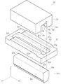
図1は本発明の一実施例に係るプレス装置用金型の全体構成を示す斜視図、図2(a)は本発明の一実施例に係る開放絞り成形方法によるプレス成形の状況(準備段階)を示す正面側断面図、図2(b)は同じく部分平面図、図3(a)は本発明の一実施例に係る開放絞り成形方法によるプレス成形の状況(成形途中)を示す正面側断面図、図3(b)は同じく部分平面図、図4(a)は本発明の一実施例に係る開放絞り成形方法によるプレス成形の状況(成形完了時)を示す正面側断面図、図4(b)は同じく部分平面図である。
Next, embodiments of the invention will be described.
FIG. 1 is a perspective view showing the entire configuration of a press device mold according to an embodiment of the present invention, and FIG. 2A is a state of press molding by an open drawing method according to an embodiment of the present invention (preparation stage). 2 (b) is a partial plan view, and FIG. 3 (a) is a front side showing the state of press forming (in the middle of forming) by the open drawing method according to one embodiment of the present invention. Sectional drawing, FIG.3 (b) is also a partial top view, FIG.4 (a) is front sectional drawing, the figure which shows the condition (at the time of shaping | molding completion) of the press molding by the open drawing method which concerns on one Example of this invention, figure 4 (b) is also a partial plan view.
本発明に係るプレス装置用金型の実施例について説明をする。
尚、前述の従来構成の説明と同様に、説明の便宜上、図1中の基準座標軸に示す矢印Xの方向(製品の長さ方向)を前方、矢印Yの方向(製品の幅方向)を右方、矢印Zの方向(製品の高さ方向)を上方として、以下の説明を行う。
また、この基準座標軸は説明の便宜上定めるものであって、本発明に係るプレス装置用金型10を構成する各部(後述するダイ1、ブランクホルダー2、ポンチ3等)の配置構成を本実施例に示す構成に限定するものではない。
An embodiment of a press device die according to the present invention will be described.
As in the description of the conventional configuration described above, for convenience of explanation, the direction of the arrow X (the product length direction) shown on the reference coordinate axis in FIG. 1 is the front, and the direction of the arrow Y (the product width direction) is the right. On the other hand, the following explanation will be made with the direction of the arrow Z (the height direction of the product) as the upper side.
This reference coordinate axis is determined for convenience of explanation, and the arrangement configuration of each part (the die 1,
図1に示す如く、本発明に係るプレス装置用金型10は、従来構成と同様に、上型たるダイ1と、ブランクホルダー2と、下型たるポンチ3等により構成される。
ダイ1の下面側には、底部1fおよび左右の側面部1g・1hからなり下方および前後方向に開放される凹部1aを形成している。また、ダイ1の下面側には、凹部1aを挟んで左右にクッション面1b・1cを形成している。さらに、クッション面1b・1cには、該クッション面1b・1cの前後方向の全長に渉って、ビード1d・1eを下方に突出して形成している。
As shown in FIG. 1, a pressing device die 10 according to the present invention is configured by an upper die 1, a
On the lower surface side of the die 1, a
また、ダイ1左右の側面部1g・1hの前後方向の両端部は、Y軸方向(即ち、完成製品の幅方向)の外側に向けて湾曲する湾曲部1j・1j・・・を形成しており、この点が従来構成に係るダイ31と相違している。
In addition, both front and rear end portions of the left and right
ブランクホルダー2は、従来構成と同様に、左右方向にブロック部2a・2bが形成される平面視略矩形状の部材であり、各ブロック部2a・2bの上面側にクッション面2c・2dを形成している。
また、クッション面2c・2dには、該クッション面2c・2dの前後方向の全長に渉って、前述したビード1d・1eに対応する溝部2e・2fを各クッション面2c・2dの上面より下方に窪ませて形成している。つまり、ブランクホルダー2の各クッション面2c・2dは、前述したダイ1の各クッション面1b・1cに対応しており、クッション面1bとクッション面2cが対面し、かつ、クッション面1cとクッション面2dが対面する構成としている。
The
The cushion surfaces 2c and 2d have
また、ブロック部2a内側の側面部2gとブロック部2b内側の側面部2hによってポンチ3が挿通される隙間を形成している。各側面部2g・2hの面間距離はポンチ3が挿通可能で、かつ、材料素材4の流入を妨げない距離に設定している。
Further, a gap through which the
さらに、側面部2g・2hの前後方向の端部には、前記ダイ1の湾曲部1j・1j・・・に対応し、Y軸方向(即ち、完成製品の幅方向)の外側に向けて湾曲する湾曲部2j・2j・・・を形成しており、この点が従来構成に係るブランクホルダー32と相違している。
Further, the end portions of the
ポンチ3の上面側には、従来構成と同様に、前述したダイ1の底部1fに対応する上面部3aを形成しており、また、左右の側面には前述したダイ1の側面部1g・1hに対応する側面部3b・3cを形成している。
On the upper surface side of the
さらに、側面部3b・3cの前後方向の端部には、前記ダイ1の湾曲部1j・1j・・・およびブランクホルダー2の湾曲部2j・2j・・・に対応し、Y軸方向(即ち、完成製品の幅方向)の外側に向けて湾曲する湾曲部3f・3f・・・を形成している。
これにより、ポンチ3の上面部3aと側面部3b・3cの境界線となるポンチ稜線3d・3eおよび後述する絞りプロファイル8も、Y軸方向(即ち、完成製品の幅方向)の外側に向けて湾曲する構成となる。
Further, the end portions of the
As a result, the
次に、本発明に係るプレス装置用金型10による開放絞り成形方法について説明をする。
まず準備段階における、プレス装置用金型10への材料素材4のセット状況およびセット方法について説明をする。
図2(a)に示す如く、従来構成と同様に、材料素材4をセットする際には、ブランクホルダー2の各クッション面2c・2dがポンチ3の上面部3aに比して上方に保持した後に、ブランクホルダー2の各クッション面2c・2d上に材料素材4を載置する。そして、ダイ1を下降させてダイ1の各ビード1d・1eがブランクホルダー2の各溝部2e・2fに嵌り込む高さに保持することにより、ダイ1の各ビード1d・1eと、ブランクホルダー2の各溝部2e・2fによって材料素材4を挟持する。
尚、従来のプレス装置用金型30と同様に、ダイ1を保持する高さや、各ビード1d・1eの高さおよび各溝部2e・2fの深さを調整することによって、ダイ1およびブランクホルダー2による材料素材4に対する挟持力を調整することが可能である。
Next, a description will be given of an open drawing method using the pressing device die 10 according to the present invention.
First, the setting situation and setting method of the
As shown in FIG. 2A, as in the conventional configuration, when the
Similar to the conventional press device die 30, the die 1 and blank holder can be adjusted by adjusting the height for holding the die 1, the height of each
また、プレス装置用金型10では、従来のプレス装置用金型30と同様に、ダイ1、ブランクホルダー2およびポンチ3によって製品形状たるキャビティ9を形成している。
Further, in the
図2(b)に示す如く、本発明に係る開放絞り成形を行う場合においても、従来と同様に完成製品の形状や材料素材4の大きさに応じて、材料素材4上に製品見切り線5を設定する。そして、材料素材4の製品見切り線5よりも外側の部位を余肉部6として設定する。
As shown in FIG. 2 (b), also in the case of performing the open drawing according to the present invention, the
さらに、絞りプロファイル8を設定し、ダイ1の側面部1g・1hとポンチ3の側面部3b・3cが接する境界線を定めている。
Further, an
また、図2(b)に示す範囲X(斜線部)が各ビード1d・1eおよび各溝部2e・2fによる挟持面7・7となり、材料素材4の変位および伸長を調整している。つまり、本発明に係るプレス装置用金型10では、従来構成に係るプレス装置用金型30と同様に、材料素材4の左右方向の各端部を挟持することができるが、材料素材4の開放側(前後方向)の各端末は挟持することができない構成としている。
Further, a range X (shaded portion) shown in FIG. 2B becomes the sandwiching surfaces 7 and 7 by the
次に、成形途中における、プレス装置用金型10および材料素材4の状況について説明をする。
図3(a)に示す如く、材料素材4を挟持した状態でダイ1およびブランクホルダー2を徐々に下降させて、前述した準備段階からプレス成形状態に移行する。
プレス成形が進行していくと、ダイ1およびブランクホルダー2によって挟持されている左右方向の各端部の材料素材4(図3(b)中に示す範囲A)は、ポンチ稜線3d・3eに対して直角方向に変位および伸長し、キャビティ9に流入する。ここでは、各ビード1d・1eおよび各溝部2e・2fによって材料素材4に挟持力を付与することによって、左右端末側の材料素材4のキャビティ9への流入量を調整している。
Next, the situation of the press die 10 and the
As shown in FIG. 3A, the die 1 and the
As the press forming proceeds, the material material 4 (range A shown in FIG. 3B) at each end in the left-right direction sandwiched between the die 1 and the
一方、ダイ1およびブランクホルダー2によって挟持されない開放側の材料素材4(図3(b)中に示す範囲B)の余肉部6は、ダイ1とブランクホルダー2によっては挟持されない状態で、Y軸方向(即ち、完成製品の幅方向)の外側に向けて湾曲するポンチ稜線3d・3eに沿って湾曲しながらキャビティ9に流入している。このとき、材料素材4をポンチ稜線3d・3eに沿って湾曲させることにより、材料素材4に対して開放側(略前後方向)への張力を付与することができる。
On the other hand, the
即ち、開放端が存在する凹部1aと該凹部1aの周囲にクッション面1b・1cが形成されるダイ1と、クッション面1b・1cと接し材料素材4を保持するブランクホルダー2と、凹部1aの底部1fに対応する上面部3aと凹部1aの両側面部1g・1hに対応する側面部3b・3cが形成されるポンチ3と、によって製品形状たるキャビティ9を形成するプレス装置用金型10による開放絞り成形方法であって、材料素材4の余肉部6に対応する範囲において、ポンチ3の幅を該ポンチ3の端部に向かって漸次拡幅させて、ポンチ3の上面部3aと側面部3b・3cが形成する境界線(ポンチ稜線3d・3e)を、ポンチ3の端部に向かってポンチ3の幅方向の外側に向けて湾曲させておき、開放絞り成形の開始当初から材料素材4をポンチ稜線3d・3eに沿ってキャビティ9に流入させて、余肉部6を該余肉部6の端部に向かって、ポンチ3の幅方向の外側に湾曲させている。
That is, a
このような構成とすることにより、材料素材4に対して、開放絞り成形の開始当初から開放方向の外側に作用する張力を付与することができ、開放絞り成形の開始当初から、プレス装置用金型10の開放側からキャビティ9に流入する材料素材4の流入量を調整することができるのである。また、これにより、完成製品にしわや割れが発生することを防止することができるのである。
By adopting such a configuration, it is possible to apply tension acting on the
また、材料素材4をポンチ稜線3d・3eに沿って湾曲させると同時に、余肉部6は、ダイ1に形成される湾曲部1j(即ち、絞りプロファイル8)に沿って、所謂ナツキ成形が施される状態となり、これによっても材料素材4に対して開放側(略前後方向)への張力を付与することができる。
In addition, the
即ち、開放端が存在する凹部1aと凹部1aの周囲にクッション面1b・1cが形成されるダイ1と、クッション面1b・1cと接し材料素材4を保持するブランクホルダー2と、凹部1aの底部1fに対応する上面部3aと凹部1aの両側面部1g・1hに対応する側面部3b・3cが形成されるポンチ3と、によって製品形状たるキャビティ9を形成するプレス装置用金型10による開放絞り成形方法であって、材料素材4の余肉部6に対応する範囲において、ポンチ3の幅を該ポンチ3の端部に向かって漸次拡幅させて、かつ、ダイ1の凹部1aの幅を該凹部1aの端部に向かって漸次拡幅させて、ポンチ3とダイ1によって設定される絞りプロファイル8を、ポンチ3および凹部1aの幅方向の外側に向けて湾曲させておき、開放絞り成形の開始当初から材料素材4を絞りプロファイル8に沿ってダイ1にナツキ成形させて、余肉部6を該余肉部6の端部に向かって、ポンチ3および凹部1aの幅方向の外側に湾曲させている。
That is, a
このような構成とすることにより、材料素材4に対して、開放絞り成形の開始当初から開放方向の外側に作用する張力を付与することができ、開放絞り成形の開始当初から、プレス装置用金型10の開放側からキャビティ9に流入する材料素材4の流入量を調整することができるのである。また、これにより、完成製品にしわや割れが発生することを防止することができるのである。
By adopting such a configuration, it is possible to apply tension acting on the
つまり、材料素材4がポンチ稜線3d・3eに接した時点(即ち、開放絞り成形の開始時点)から材料素材4に対して開放側(略前後方向)への張力を付与することができる。
換言すれば、係る構成では、ダイ1およびブランクホルダー2によって挟持されない開放側の材料素材4(図3(b)中に示す範囲B)が自由にキャビティ9に流入するタイミングが発生しないのである。
That is, it is possible to apply a tension in the open side (substantially in the front-rear direction) to the
In other words, in such a configuration, the timing at which the open-side material material 4 (range B shown in FIG. 3B) that is not sandwiched between the die 1 and the
次に、成形完了時における、プレス装置用金型10および材料素材4の状況について説明をする。
図4(a)に示す如く、ダイ1およびブランクホルダー2が下死点にまで達すると、ダイ1およびブランクホルダー2によって挟持されている左右方向の各端部の材料素材4(図4(b)中に示す範囲A)は、ポンチ稜線3d・3eに対して直角方向にさらに変位および伸長し、キャビティ9に流入する。
Next, the situation of the
As shown in FIG. 4A, when the die 1 and the
一方、ダイ31およびブランクホルダー32によって挟持されない開放側の材料素材4(図4(b)中に示す範囲B)は、ポンチ稜線3d・3eに沿って湾曲しながらキャビティ9にさらに流入し、かつ、ダイ1に形成される湾曲部1j(即ち、絞りプロファイル8)に沿って、さらにナツキ成形が施されることにより、開放側(前後方向)に適切な張力が付与されて、流入が拘束された状態を維持している。
On the other hand, the open-side material material 4 (range B shown in FIG. 4B) that is not sandwiched between the die 31 and the
即ち、開放端が存在する凹部1aと凹部1aの周囲にクッション面1b・1cが形成されるダイ1と、クッション面1b・1cと接し材料素材4を保持するブランクホルダー2と、凹部1aの底部1fに対応する上面部3aと凹部1aの両側面部1g・1hに対応する側面部3b・3cが形成されるポンチ3と、によって製品形状たるキャビティ9を形成するプレス装置用金型10による開放絞り成形方法であって、材料素材4の余肉部6に対応する範囲において、ポンチ3の幅を該ポンチ3の端部に向かって漸次拡幅させて、ポンチ3の上面部3aと側面部3b・3cが形成する境界線(即ち、ポンチ稜線3d・3e)を、ポンチ3の端部に向かって該ポンチ3の幅方向の外側に向けて湾曲させておき、開放絞り成形の開始当初から材料素材4をポンチ稜線3d・3eに沿ってキャビティ9に流入させて、かつ、ダイ1の凹部1aの幅を該凹部1aの端部に向かって漸次拡幅させて、ポンチ3とダイ1によって設定される絞りプロファイル8を、ポンチ3および凹部1aの幅方向の外側に向けて湾曲させておき、開放絞り成形の開始当初から材料素材4を絞りプロファイル8に沿ってダイ1にナツキ成形させて、余肉部6を該余肉部6の端部に向かって、ポンチ3および凹部1aの幅方向の外側に湾曲させている。
That is, a
このような構成とすることにより、ポンチ稜線3d・3eに沿って余肉部6を湾曲させて得る張力と、余肉部6をダイ1の湾曲部1j(即ち、絞りプロファイル8)に沿ってナツキ成形させて得る張力によって相乗的な効果が得られるため、材料素材4に対して、開放絞り成形の開始当初から開放方向の外側に作用する張力をより確実に付与することができ、開放絞り成形の開始当初から、プレス装置用金型10の開放側からキャビティ9に流入する材料素材4の流入量をより適切に調整することができるのである。また、これにより、完成製品にしわや割れが発生することをより確実に防止することができるのである。
With such a configuration, the tension obtained by bending the
つまり、本発明に係る絞り成形方法では、成形途中の過程で余肉部6や材料素材4の端末を拘束することができ、ダイ1およびブランクホルダー2が下死点にまで達しなくとも、余肉部6や材料素材4の端末を拘束することができる。これにより、余分に余肉部6を設定すること無く、開放側の材料素材の流入を拘束する十分な効果を得ることができるのである。
That is, in the drawing method according to the present invention, the
このため、本発明に係るプレス装置用金型10による開放絞り成形においては、従来構成に係るプレス装置用金型による開放絞り成形のように、開放側からの材料素材の流入に起因するしわが発生しない。さらに、余肉部6の設定範囲を削減することが可能となり、材料素材4の歩留まりを改善することができる。
For this reason, in the open drawing with the
尚、平面視におけるダイ1の湾曲部1jおよびポンチ3の湾曲部3fの曲率を小さく設定するほど、材料素材4に対して付与する完成製品の長さ方向に作用する張力を大きくすることができる。
つまり、材料素材4のキャビティ9への流入量は、平面視における前記湾曲部1j・3fの曲率を変更することで容易に調整することができるため、型修正による材料素材4の流入量の微調整を容易にすることができる。
また、製品見切り線5よりも外側における余肉部6の縦壁角度(即ち、図4(a)中に示す角度θ)を小さく設定するほど、材料素材4に対して開放側(即ち、完成製品の長さ方向)に付与する張力を大きくすることができる。
The smaller the curvature of the
That is, the inflow amount of the
In addition, the smaller the vertical wall angle of the
1 ダイ
2 ブランクホルダー
3 ポンチ
3a 上面部
3b 側面部
3c 側面部
3d ポンチ稜線
3e ポンチ稜線
3f 湾曲部
4 材料素材
6 余肉部
8 絞りプロファイル
9 キャビティ
DESCRIPTION OF SYMBOLS 1
Claims (6)
前記クッション面と接し材料素材を保持するブランクホルダーと、
前記凹部の底部に対応する上面部と前記凹部の両側部に対応する側面部が形成されるポンチと、
によって製品形状たるキャビティを形成するプレス装置用金型による開放絞り成形方法であって、
前記材料素材に対して製品範囲として設定される製品見切り線よりも該材料素材の端部側であって、かつ、前記ダイの前記開放端側に位置し、前記ダイおよび前記ブランクホルダーによって挟持されない余肉部に対応する範囲において、
前記ポンチの幅を該ポンチの端部に向かって漸次拡幅させて、
前記ポンチの前記上面部と前記側面部が形成する境界線を、
前記ポンチの端部に向かって該ポンチの幅方向の外側へ湾曲させておき、
開放絞り成形の開始当初から前記材料素材を前記境界線に沿って前記キャビティに流入させて、
前記余肉部を該余肉部の端部に向かって、前記ポンチの幅方向の外側に湾曲させる、
ことを特徴とする開放絞り成形方法。 A die formed with a recess having an open end and a cushion surface disposed around the recess;
A blank holder that holds the material material in contact with the cushion surface;
A punch formed with a top surface corresponding to the bottom of the recess and a side surface corresponding to both sides of the recess;
An open drawing method using a mold for a press device that forms a cavity that is a product shape by:
It is located on the end side of the material material with respect to the product parting line set as the product range for the material material, and is located on the open end side of the die, and is not sandwiched between the die and the blank holder. In the range corresponding to the surplus part,
The width of the punch is gradually increased toward the end of the punch,
A boundary line formed by the upper surface portion and the side surface portion of the punch,
Curved outward in the width direction of the punch toward the end of the punch,
The material material is allowed to flow into the cavity along the boundary line from the beginning of open drawing,
Curving the surplus portion toward the end of the surplus portion, outward in the width direction of the punch,
An open-drawing method characterized by that.
前記クッション面と接し材料素材を保持するブランクホルダーと、
前記凹部の底部に対応する上面部と前記凹部の両側部に対応する側面部が形成されるポンチと、
によって製品形状たるキャビティを形成するプレス装置用金型による開放絞り成形方法であって、
前記材料素材に対して製品範囲として設定される製品見切り線よりも該材料素材の端部側であって、かつ、前記ダイの前記開放端側に位置し、前記ダイおよび前記ブランクホルダーによって挟持されない余肉部に対応する範囲において、
前記ポンチの幅を該ポンチの端部に向かって漸次拡幅させて、かつ、
前記ダイの凹部の幅を該凹部の端部に向かって漸次拡幅させて、
前記ポンチと前記ダイによって設定される絞りプロファイルを、
前記ポンチおよび前記凹部の端部に向かって、前記ポンチおよび前記凹部の幅方向の外側へ湾曲させておき、
開放絞り成形の開始当初から前記材料素材を前記ダイの前記絞りプロファイルに沿って絞り成形させて、
前記余肉部を該余肉部の端部に向かって、前記ポンチおよび前記凹部の幅方向の外側へ湾曲させる、
ことを特徴とする開放絞り成形方法。 A die formed with a recess having an open end and a cushion surface disposed around the recess;
A blank holder that holds the material material in contact with the cushion surface;
A punch formed with a top surface corresponding to the bottom of the recess and a side surface corresponding to both sides of the recess;
An open drawing method using a mold for a press device that forms a cavity that is a product shape by:
It is located on the end side of the material material with respect to the product parting line set as the product range for the material material, and is located on the open end side of the die, and is not sandwiched between the die and the blank holder. In the range corresponding to the surplus part,
Gradually increasing the width of the punch toward the end of the punch; and
The width of the concave portion of the die is gradually widened toward the end of the concave portion,
The aperture profile set by the punch and the die
To the end of the punch and the recess, curved outward in the width direction of the punch and the recess,
From the beginning of open drawing, the material material is drawn along the drawing profile of the die,
Curving the surplus portion toward the end of the surplus portion, outward in the width direction of the punch and the recess,
An open-drawing method characterized by that.
前記クッション面と接し材料素材を保持するブランクホルダーと、
前記凹部の底部に対応する上面部と前記凹部の両側部に対応する側面部が形成されるポンチと、
によって製品形状たるキャビティを形成するプレス装置用金型による開放絞り成形方法であって、
前記材料素材に対して製品範囲として設定される製品見切り線よりも該材料素材の端部側であって、かつ、前記ダイの前記開放端側に位置し、前記ダイおよび前記ブランクホルダーによって挟持されない余肉部に対応する範囲において、
前記ポンチの幅を該ポンチの端部に向かって漸次拡幅させて、
前記ポンチの前記上面部と前記側面部が形成する境界線を、
前記ポンチの端部に向かって該ポンチの幅方向の外側へ湾曲させておき、
開放絞り成形の開始当初から前記材料素材を前記境界線に沿って前記キャビティに流入させて、かつ、
前記ダイの凹部の幅を該凹部の端部に向かって漸次拡幅させて、
前記ポンチと前記ダイによって設定される絞りプロファイルを、
前記ポンチおよび前記凹部の端部に向かって、前記ポンチおよび前記凹部の幅方向の外側へ湾曲させておき、
開放絞り成形の開始当初から前記材料素材を前記ダイの前記絞りプロファイルに沿って絞り成形させて、
前記余肉部を該余肉部の端部に向かって、
前記ポンチおよび前記凹部の幅方向の外側に湾曲させる、
ことを特徴とする開放絞り成形方法。 A die formed with a recess having an open end and a cushion surface disposed around the recess;
A blank holder that holds the material material in contact with the cushion surface;
A punch formed with a top surface corresponding to the bottom of the recess and a side surface corresponding to both sides of the recess;
An open drawing method using a mold for a press device that forms a cavity that is a product shape by:
It is located on the end side of the material material with respect to the product parting line set as the product range for the material material, and is located on the open end side of the die, and is not sandwiched between the die and the blank holder. In the range corresponding to the surplus part,
The width of the punch is gradually increased toward the end of the punch,
A boundary line formed by the upper surface portion and the side surface portion of the punch,
Curved outward in the width direction of the punch toward the end of the punch,
Allowing the material material to flow into the cavity along the boundary line from the beginning of open drawing, and
The width of the concave portion of the die is gradually widened toward the end of the concave portion,
The aperture profile set by the punch and the die
To the end of the punch and the recess, curved outward in the width direction of the punch and the recess,
From the beginning of open drawing, the material material is drawn along the drawing profile of the die,
The surplus portion is directed toward the end of the surplus portion,
Curving outward in the width direction of the punch and the recess,
An open-drawing method characterized by that.
前記クッション面と接し材料素材を保持するブランクホルダーと、
前記凹部の底部に対応する上面部と前記凹部の両側部に対応する側面部が形成されるポンチと、
からなる開放絞り成形に用いるプレス装置用金型であって、
前記材料素材に対して製品範囲として設定される製品見切り線よりも該材料素材の端部側であって、かつ、前記ダイの前記開放端側に位置し、前記ダイおよび前記ブランクホルダーによって挟持されない余肉部に対応する範囲において、
前記ポンチの幅を該ポンチの端部に向かって漸次拡幅させて、
前記ポンチの前記上面部と前記側面部によって形成される境界線を、
前記ポンチの端部に向かって、前記ポンチの幅方向の外側へ湾曲させる、
ことを特徴とするプレス装置用金型。 A die formed with a recess having an open end and a cushion surface disposed around the recess;
A blank holder that holds the material material in contact with the cushion surface;
A punch formed with a top surface corresponding to the bottom of the recess and a side surface corresponding to both sides of the recess;
A mold for a press device used for open drawing molding comprising:
It is located on the end side of the material material with respect to the product parting line set as the product range for the material material, and is located on the open end side of the die, and is not sandwiched between the die and the blank holder. In the range corresponding to the surplus part,
The width of the punch is gradually increased toward the end of the punch,
A boundary line formed by the upper surface portion and the side surface portion of the punch,
Curving outward in the width direction of the punch toward the end of the punch,
A metal mold for a press device.
前記クッション面と接し材料素材を保持するブランクホルダーと、
前記凹部の底部に対応する上面部と前記凹部の両側部に対応する側面部が形成されるポンチと、
からなる開放絞り成形に用いるプレス装置用金型であって、
前記材料素材に対して製品範囲として設定される製品見切り線よりも該材料素材の端部側であって、かつ、前記ダイの前記開放端側に位置し、前記ダイおよび前記ブランクホルダーによって挟持されない余肉部に対応する範囲において、
前記ポンチの幅を該ポンチの端部に向かって漸次拡幅させて、かつ、
前記ダイの凹部の幅を該凹部の端部に向かって漸次拡幅させて、
前記ポンチと前記ダイによって設定される絞りプロファイルを、
前記ポンチおよび前記凹部の端部に向かって、前記ポンチおよび前記凹部の幅方向の外側へ湾曲させる、
ことを特徴とするプレス装置用金型。 A die formed with a recess having an open end and a cushion surface disposed around the recess;
A blank holder that holds the material material in contact with the cushion surface;
A punch formed with a top surface corresponding to the bottom of the recess and a side surface corresponding to both sides of the recess;
A mold for a press device used for open drawing molding comprising:
It is located on the end side of the material material with respect to the product parting line set as the product range for the material material, and is located on the open end side of the die, and is not sandwiched between the die and the blank holder. In the range corresponding to the surplus part,
Gradually increasing the width of the punch toward the end of the punch; and
The width of the concave portion of the die is gradually widened toward the end of the concave portion,
The aperture profile set by the punch and the die
Curve outward in the width direction of the punch and the recess toward the end of the punch and the recess,
A metal mold for a press device.
前記クッション面と接し材料素材を保持するブランクホルダーと、
前記凹部の底部に対応する上面部と前記凹部の両側部に対応する側面部が形成されるポンチと、
からなる開放絞り成形に用いるプレス装置用金型であって、
前記材料素材に対して製品範囲として設定される製品見切り線よりも該材料素材の端部側であって、かつ、前記ダイの前記開放端側に位置し、前記ダイおよび前記ブランクホルダーによって挟持されない余肉部に対応する範囲において、
前記ポンチの幅を該ポンチの端部に向かって漸次拡幅させて、
前記ポンチの前記上面部と前記側面部によって形成される境界線を、
前記ポンチの端部に向かって、前記ポンチの幅方向の外側へ湾曲させ、かつ、
前記ダイの凹部の幅を該凹部の端部に向かって漸次拡幅させて、
前記ポンチと前記ダイによって設定される絞りプロファイルを、
前記ポンチおよび前記凹部の端部に向かって、前記ポンチおよび前記凹部の幅方向の外側へ湾曲させる、
ことを特徴とするプレス装置用金型。 A die formed with a recess having an open end and a cushion surface disposed around the recess;
A blank holder that holds the material material in contact with the cushion surface;
A punch formed with a top surface corresponding to the bottom of the recess and a side surface corresponding to both sides of the recess;
A mold for a press device used for open drawing molding comprising:
It is located on the end side of the material material with respect to the product parting line set as the product range for the material material, and is located on the open end side of the die, and is not sandwiched between the die and the blank holder. In the range corresponding to the surplus part,
The width of the punch is gradually increased toward the end of the punch,
A boundary line formed by the upper surface portion and the side surface portion of the punch,
Curved outward in the width direction of the punch toward the end of the punch; and
The width of the concave portion of the die is gradually widened toward the end of the concave portion,
The aperture profile set by the punch and the die
Curve outward in the width direction of the punch and the recess toward the end of the punch and the recess,
A metal mold for a press device.
Priority Applications (5)
| Application Number | Priority Date | Filing Date | Title |
|---|---|---|---|
| JP2007310965A JP4386130B2 (en) | 2007-11-30 | 2007-11-30 | Mold for press machine and open drawing method |
| US12/678,593 US8490455B2 (en) | 2007-11-30 | 2008-11-11 | Mold for press apparatus, and open-drawing method |
| EP08855410A EP2202011B1 (en) | 2007-11-30 | 2008-11-11 | Mold for press apparatus, and open-drawing method |
| CN2008801176865A CN101873901B (en) | 2007-11-30 | 2008-11-11 | Mold for press apparatus, and open-drawing method |
| PCT/JP2008/070464 WO2009069461A1 (en) | 2007-11-30 | 2008-11-11 | Mold for press apparatus, and open-drawing method |
Applications Claiming Priority (1)
| Application Number | Priority Date | Filing Date | Title |
|---|---|---|---|
| JP2007310965A JP4386130B2 (en) | 2007-11-30 | 2007-11-30 | Mold for press machine and open drawing method |
Publications (2)
| Publication Number | Publication Date |
|---|---|
| JP2009131878A JP2009131878A (en) | 2009-06-18 |
| JP4386130B2 true JP4386130B2 (en) | 2009-12-16 |
Family
ID=40678363
Family Applications (1)
| Application Number | Title | Priority Date | Filing Date |
|---|---|---|---|
| JP2007310965A Expired - Fee Related JP4386130B2 (en) | 2007-11-30 | 2007-11-30 | Mold for press machine and open drawing method |
Country Status (5)
| Country | Link |
|---|---|
| US (1) | US8490455B2 (en) |
| EP (1) | EP2202011B1 (en) |
| JP (1) | JP4386130B2 (en) |
| CN (1) | CN101873901B (en) |
| WO (1) | WO2009069461A1 (en) |
Cited By (1)
| Publication number | Priority date | Publication date | Assignee | Title |
|---|---|---|---|---|
| JP2020199539A (en) * | 2019-06-11 | 2020-12-17 | トヨタ車体株式会社 | Press molding method for vehicular member component and press die therefor |
Families Citing this family (17)
| Publication number | Priority date | Publication date | Assignee | Title |
|---|---|---|---|---|
| KR100949463B1 (en) * | 2009-08-26 | 2010-03-29 | (주)명진 | Chassis embossing apparatus |
| JP2013518723A (en) | 2010-02-04 | 2013-05-23 | クラウン パッケイジング テクノロジー インコーポレイテッド | Can manufacturing |
| WO2011128347A1 (en) * | 2010-04-12 | 2011-10-20 | Crown Packaging Technology, Inc. | Can manufacture |
| US9067251B2 (en) * | 2011-06-13 | 2015-06-30 | GM Global Technology Operations LLC | Method of forming an article from metal alloy sheet material |
| CN103357735B (en) * | 2012-04-01 | 2015-05-13 | 上海赛科利汽车模具技术应用有限公司 | Opening drawing and forming process of vehicle door inner plate |
| CN102632157A (en) * | 2012-05-04 | 2012-08-15 | 吉林大学 | Crimping and rebounding control method of lateral wall of advanced high-strength steel stamping part |
| US20140020534A1 (en) * | 2012-07-17 | 2014-01-23 | National Taiwan Ocean University | Fine hydro-blanking device |
| HUE060567T2 (en) * | 2013-05-13 | 2023-03-28 | Nippon Steel Corp | Method of manufacturing a worked component |
| FR3005880B1 (en) * | 2013-05-22 | 2015-05-29 | Peugeot Citroen Automobiles Sa | PROCESS FOR PADLING A WORKPIECE, IN PARTICULAR BODY OF A MOTOR VEHICLE, WITH IMPROVED CLAMP SOCKET |
| FR3019765A1 (en) * | 2014-04-10 | 2015-10-16 | Peugeot Citroen Automobiles Sa | FLAN GREEN ARRANGEMENT IN A BINDING TOOL |
| FR3040642B1 (en) * | 2015-09-03 | 2017-08-25 | Peugeot Citroen Automobiles Sa | FLUID SQUEEGEE OF BINDING TOOL FOR AUTOMOTIVE BODY LINING. |
| FR3045424B1 (en) * | 2015-12-18 | 2018-01-26 | Psa Automobiles Sa. | METHOD OF PADLING A FLAN OF THE SHEET USING A PRESS TO OBTAIN A U-PIECE AND PRESS FOR SUCH A METHOD OF PACKING |
| US10406587B2 (en) * | 2016-03-31 | 2019-09-10 | GM Global Technology Operations LLC | Method and die set for forming a surface in a metal panel |
| CN105921621A (en) * | 2016-06-06 | 2016-09-07 | 深圳市信维通信股份有限公司 | Drawing method and drawing mould for U-shaped drawn component |
| DE102017120192A1 (en) * | 2017-09-01 | 2019-03-07 | Benteler Automobiltechnik Gmbh | Hold-down press for producing a semifinished product from sheet material with thinned areas and method for producing a Blechumformbauteils |
| JP7454433B2 (en) | 2020-04-09 | 2024-03-22 | 東プレ株式会社 | Manufacturing method for hat-shaped molded parts and mold |
| JP2023029056A (en) * | 2021-08-20 | 2023-03-03 | 本田技研工業株式会社 | Forming apparatus and forming method using forming apparatus |
Family Cites Families (15)
| Publication number | Priority date | Publication date | Assignee | Title |
|---|---|---|---|---|
| US3263637A (en) * | 1964-12-23 | 1966-08-02 | Darwin S Cox | Method of deep drawing rectangular shapes |
| JPS582501Y2 (en) * | 1979-01-19 | 1983-01-17 | 東京プレス工業株式会社 | press mold |
| FR2564339B1 (en) * | 1984-05-17 | 1987-12-24 | Usinor | METHOD AND DEVICE FOR STAMPING SHEETS. |
| US4615205A (en) * | 1984-06-18 | 1986-10-07 | Rca Corporation | Forming a shadow mask from a flat blank |
| US4719787A (en) * | 1986-08-29 | 1988-01-19 | Rca Corporation | Apparatus for forming a shadow mask |
| JP2547772B2 (en) * | 1987-06-13 | 1996-10-23 | 日産自動車株式会社 | Drawing method |
| JP2506400B2 (en) | 1988-02-01 | 1996-06-12 | 日産自動車株式会社 | Drawing method |
| JPH0255624A (en) * | 1988-08-22 | 1990-02-26 | Toyota Motor Corp | Forming method for product having recessed part opening one side part |
| JPH0446637A (en) * | 1990-06-14 | 1992-02-17 | Nissan Motor Co Ltd | Press die |
| JPH0825097A (en) | 1994-07-19 | 1996-01-30 | Kawasaki Steel Corp | Die for press working |
| JP2000102824A (en) | 1998-09-29 | 2000-04-11 | Matsushita Electric Ind Co Ltd | Molding die |
| JP3864038B2 (en) * | 1999-07-30 | 2006-12-27 | 伊田 忠一 | Deep drawing method |
| JP4046637B2 (en) * | 2003-04-11 | 2008-02-13 | 株式会社技研製作所 | Pile press-fitting device |
| DE112005002868B4 (en) * | 2004-11-24 | 2010-07-01 | Honda Motor Co., Ltd. | Drawing-forming method and apparatus |
| JP4787548B2 (en) * | 2005-06-07 | 2011-10-05 | 株式会社アミノ | Thin plate forming method and apparatus |
-
2007
- 2007-11-30 JP JP2007310965A patent/JP4386130B2/en not_active Expired - Fee Related
-
2008
- 2008-11-11 EP EP08855410A patent/EP2202011B1/en not_active Not-in-force
- 2008-11-11 WO PCT/JP2008/070464 patent/WO2009069461A1/en active Application Filing
- 2008-11-11 US US12/678,593 patent/US8490455B2/en active Active
- 2008-11-11 CN CN2008801176865A patent/CN101873901B/en not_active Expired - Fee Related
Cited By (2)
| Publication number | Priority date | Publication date | Assignee | Title |
|---|---|---|---|---|
| JP2020199539A (en) * | 2019-06-11 | 2020-12-17 | トヨタ車体株式会社 | Press molding method for vehicular member component and press die therefor |
| JP7153273B2 (en) | 2019-06-11 | 2022-10-14 | トヨタ車体株式会社 | Press molding method for vehicle member parts and its press mold |
Also Published As
| Publication number | Publication date |
|---|---|
| EP2202011A4 (en) | 2011-10-05 |
| CN101873901B (en) | 2013-01-16 |
| US20100201031A1 (en) | 2010-08-12 |
| EP2202011A1 (en) | 2010-06-30 |
| JP2009131878A (en) | 2009-06-18 |
| CN101873901A (en) | 2010-10-27 |
| EP2202011B1 (en) | 2012-10-31 |
| US8490455B2 (en) | 2013-07-23 |
| WO2009069461A1 (en) | 2009-06-04 |
Similar Documents
| Publication | Publication Date | Title |
|---|---|---|
| JP4386130B2 (en) | Mold for press machine and open drawing method | |
| CN105792957B (en) | Compression molding device, used the shaped device compressing product manufacture method and compressing product | |
| US9731339B2 (en) | Method for producing press-molded article | |
| KR20140148495A (en) | Method of forming structure having closed cross section, and device for forming structure having closed cross section | |
| JP5353329B2 (en) | Press molding method and press molding apparatus excellent in shape freezing property, and manufacturing method of the press molding apparatus | |
| JP6315163B1 (en) | Method and apparatus for manufacturing a press-formed product | |
| KR20110020920A (en) | Workpiece bending method and apparatus | |
| JP2006231337A (en) | Method for bending metallic pipe | |
| EP3646961A1 (en) | Method for manufacturing press molded product | |
| WO2015133224A1 (en) | Method for bending plate-shaped workpiece, mold, and bent article | |
| KR20150093207A (en) | Method for manufacturing metal component with three-dimensional edge, and die for manufacturing | |
| JP2018051584A (en) | Press molding apparatus | |
| JP5689726B2 (en) | Manufacturing apparatus and manufacturing method of overhang molded product | |
| JP6319383B2 (en) | Manufacturing method of stretch flange molded parts | |
| JP2010201495A (en) | Method for manufacturing connecting rod, and coining die apparatus used therefor | |
| JP2007152417A (en) | Bending die device and bending method | |
| RU2666805C2 (en) | Device and method for manufacture of articles by stamping | |
| JP6686853B2 (en) | Press molding equipment | |
| TW202016409A (en) | Embossed metal plate and method for producing same | |
| CN110961528A (en) | Bending and stamping die for scratch-free frame | |
| JP3683164B2 (en) | Punching method and apparatus | |
| JP5332925B2 (en) | Press molding method with excellent dimensional accuracy of molded products | |
| KR101129496B1 (en) | Apparatus and method for forming panel | |
| JP2004188473A (en) | Press working method excellent in shape freezing property | |
| JP6750569B2 (en) | Drawing press processing method |
Legal Events
| Date | Code | Title | Description |
|---|---|---|---|
| TRDD | Decision of grant or rejection written | ||
| A01 | Written decision to grant a patent or to grant a registration (utility model) |
Free format text: JAPANESE INTERMEDIATE CODE: A01 Effective date: 20090908 |
|
| A01 | Written decision to grant a patent or to grant a registration (utility model) |
Free format text: JAPANESE INTERMEDIATE CODE: A01 |
|
| A61 | First payment of annual fees (during grant procedure) |
Free format text: JAPANESE INTERMEDIATE CODE: A61 Effective date: 20090921 |
|
| R151 | Written notification of patent or utility model registration |
Ref document number: 4386130 Country of ref document: JP Free format text: JAPANESE INTERMEDIATE CODE: R151 |
|
| FPAY | Renewal fee payment (event date is renewal date of database) |
Free format text: PAYMENT UNTIL: 20121009 Year of fee payment: 3 |
|
| FPAY | Renewal fee payment (event date is renewal date of database) |
Free format text: PAYMENT UNTIL: 20121009 Year of fee payment: 3 |
|
| FPAY | Renewal fee payment (event date is renewal date of database) |
Free format text: PAYMENT UNTIL: 20131009 Year of fee payment: 4 |
|
| LAPS | Cancellation because of no payment of annual fees |