JP4385257B2 - Negative pressure supply device - Google Patents
Negative pressure supply device Download PDFInfo
- Publication number
- JP4385257B2 JP4385257B2 JP2004286681A JP2004286681A JP4385257B2 JP 4385257 B2 JP4385257 B2 JP 4385257B2 JP 2004286681 A JP2004286681 A JP 2004286681A JP 2004286681 A JP2004286681 A JP 2004286681A JP 4385257 B2 JP4385257 B2 JP 4385257B2
- Authority
- JP
- Japan
- Prior art keywords
- negative pressure
- vacuum pump
- suction port
- pressure supply
- ejector
- Prior art date
- Legal status (The legal status is an assumption and is not a legal conclusion. Google has not performed a legal analysis and makes no representation as to the accuracy of the status listed.)
- Active
Links
Images


Landscapes
- Valves And Accessory Devices For Braking Systems (AREA)
- Compressors, Vaccum Pumps And Other Relevant Systems (AREA)
- Jet Pumps And Other Pumps (AREA)
Description
本発明は、自動車の制動装置の気圧式倍力装置等に負圧を供給するための負圧供給装置に関するものである。 The present invention relates to a negative pressure supply device for supplying negative pressure to a pneumatic booster or the like of an automobile braking device.
一般的に、自動車の制動装置においては、制動力を高めるために気圧式倍力装置が設けられている。この気圧式倍力装置は、負圧源として、エンジンの吸気負圧を利用しており、吸気負圧を定圧室(負圧室)に導入して、大気圧との差圧によってパワーピストンに推力を発生させて制動装置の操作力を補助している。 In general, a braking device for an automobile is provided with a pneumatic booster to increase the braking force. This atmospheric pressure booster uses the intake negative pressure of the engine as a negative pressure source, introduces the intake negative pressure into the constant pressure chamber (negative pressure chamber), and supplies it to the power piston by the differential pressure from the atmospheric pressure. Thrust is generated to assist the operating force of the braking device.
近年、自動車のエンジンにおいては、低燃費の要求から、ポンピングロスの低減がなされており、このため、吸気管負圧が減少する傾向にあり、気圧式倍力装置に供給する負圧の不足が問題となってきている。
これに対して、例えば特許文献1に示されるように、気圧式倍力装置の負圧源として、電動の回転式真空ポンプを用いることにより、エンジンの運転状態にかかわらず、気圧式倍力装置に充分な負圧を供給することが可能である。
On the other hand, as shown in
しかしながら、上記公報記載の真空ポンプでは、次のような問題がある。真空ポンプとしてベーンポンプを使用しているが、ベーンポンプは、構造が複雑で製造コストが高く、また、小型化が困難である。単純な構造の往復動ピストン型真空ポンプを使用することも考えられるが、往復動ピストン型真空ポンプは、ピストンの背圧として大気圧が作用するため、気圧式倍力装置に必要な高い真空度を得ようとすると、負荷変動が大きくなり、円滑な運転が困難になる。 However, the vacuum pump described in the above publication has the following problems. Although the vane pump is used as the vacuum pump, the vane pump has a complicated structure, a high manufacturing cost, and is difficult to reduce in size. Although it is conceivable to use a reciprocating piston type vacuum pump with a simple structure, the reciprocating piston type vacuum pump has a high degree of vacuum required for a pneumatic booster because atmospheric pressure acts as the back pressure of the piston. If it is going to obtain, load fluctuation will become large and smooth operation will become difficult.
本発明は、上記の点に鑑みてなされたものであり、単純な構造で、高い真空度の負圧を供給することができる負圧供給装置を提供することを目的とする。 The present invention has been made in view of the above points, and an object of the present invention is to provide a negative pressure supply device that can supply a high vacuum with a simple structure.
上記の課題を解決するために、請求項1の発明に係る負圧供給装置は、ノズルの下流側にディフューザを配置して、これらの間に吸引口を開口させたエジェクタと、真空ポンプとを有し、前記ノズルの入口に前記真空ポンプの吐出口からの吐出空気のみを供給すると共に前記ディフューザの出口に前記真空ポンプの吸込口を接続し、前記エジェクタの吸引口と前記真空ポンプの吸込口から負圧を供給することを特徴とする。
請求項2の発明に係る負圧供給装置は、上記請求項1の構成において、前記吸引口及び前記真空ポンプの吸込口をそれぞれ逆止弁を介して負圧供給口に接続し、前記吸引口及び前記吸込口のうち、真空度の高いほうの負圧を前記負圧供給口から供給することを特徴とする。
請求項3の発明に係る負圧供給装置は、上記請求項1又は2の構成において、前記真空ポンプは、リニアアクチュエータによって駆動されるピストンを有する往復動ポンプであることを特徴とする。
請求項4の発明に係る負圧供給措置は、上記請求項1乃至3のいずれかの構成において、前記真空ポンプの吐出側をエンジン吸気管に接続したことを特徴とする。
請求項5の発明に係る負圧供給装置は、上記請求項4の構成において、前記真空ポンプの吐出側を大気に開放する第3逆止弁を設けたことを特徴とする。
In order to solve the above-mentioned problem, a negative pressure supply device according to the invention of
A negative pressure supply device according to a second aspect of the present invention is the structure of the first aspect, wherein the suction port and the suction port of the vacuum pump are each connected to a negative pressure supply port via a check valve, and the suction port Of the suction ports, the negative pressure having a higher degree of vacuum is supplied from the negative pressure supply port.
A negative pressure supply device according to a third aspect of the invention is characterized in that, in the configuration of the first or second aspect, the vacuum pump is a reciprocating pump having a piston driven by a linear actuator.
According to a fourth aspect of the present invention, there is provided the negative pressure supply means according to any one of the first to third aspects, wherein the discharge side of the vacuum pump is connected to an engine intake pipe.
According to a fifth aspect of the present invention, the negative pressure supply device according to the fourth aspect is characterized in that a third check valve is provided to open the discharge side of the vacuum pump to the atmosphere.
請求項1の発明に係る負圧供給装置によれば、真空ポンプの吸込によって、エジェクタのノズルからディフューザへ空気が流れ、これにより、ノズルのスロート部に高速噴流が生じて、吸引口に、真空ポンプの吸込負圧よりも高い真空度の負圧が発生し、この高い真空度の負圧を供給することができる。また、真空ポンプは、エジェクタのノズルの入口に供給する空気を負圧作動装置から吸入することになるので、負圧作動装置に効率よく負圧を供給することができる。
請求項2の発明に係る負圧供給装置によれば、逆止弁によってエジェクタの吸引口又は真空ポンプの吸込口のいずれか真空度の高いほうの負圧を供給することができるので、効率よく負圧を供給することができる。
請求項3の発明に係る負圧供給装置によれば、真空ポンプの構造を簡素化することができ、小型化及び製造コストの低減が可能となる。
請求項4の発明に係る負圧供給装置によれば、エンジン吸気負圧を真空ポンプの吐出側に供給することができ、真空ポンプの負担を軽減することができる。
請求項5の発明に係る負圧供給装置によれば、真空ポンプの吐出側が正圧になると、第3逆止弁が開いて、その圧力を大気に開放するので、過給機の過給によって真空ポンプの吐出側が正圧になるのを防止することができる。
According to the negative pressure supply device of the first aspect of the present invention, air flows from the nozzle of the ejector to the diffuser by suction of the vacuum pump, thereby generating a high-speed jet at the throat portion of the nozzle, and a vacuum at the suction port. A negative pressure with a vacuum level higher than the suction negative pressure of the pump is generated, and this high vacuum level negative pressure can be supplied. Further, since the vacuum pump sucks air supplied to the inlet of the nozzle of the ejector from the negative pressure operating device, the negative pressure can be efficiently supplied to the negative pressure operating device.
According to the negative pressure supply device of the second aspect of the invention, the negative pressure of the higher vacuum degree of the suction port of the ejector or the suction port of the vacuum pump can be supplied by the check valve. Negative pressure can be supplied.
According to the negative pressure supply device of the third aspect of the invention, the structure of the vacuum pump can be simplified, and downsizing and manufacturing cost can be reduced.
According to the negative pressure supply device of the fourth aspect of the invention, the engine intake negative pressure can be supplied to the discharge side of the vacuum pump, and the burden on the vacuum pump can be reduced.
According to the negative pressure supply device of the fifth aspect of the invention, when the discharge side of the vacuum pump becomes positive pressure, the third check valve opens and the pressure is released to the atmosphere. It is possible to prevent the discharge side of the vacuum pump from becoming a positive pressure.
以下、本発明の実施形態を図面に基づいて詳細に説明する。
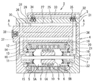
本発明の第1実施形態について、図1乃至図3を参照して説明する。図1乃至図3に示すように、本実施形態に係る負圧供給装置1は、真空ポンプユニット2(真空ポンプ)と、エジェクタユニット3とをマニホールドユニット4を介して結合した構成となっている。
Hereinafter, embodiments of the present invention will be described in detail with reference to the drawings.
A first embodiment of the present invention will be described with reference to FIGS. 1 to 3. As shown in FIGS. 1 to 3, the negative
真空ポンプユニット2は、可動磁石型リニアモータによって駆動されるピストンを有する往復動ポンプであって、固定子を兼ねるシリンダ5内に、可動子を兼ねるピストン6が摺動可能に嵌装されている。ピストン6は、シリンダ5の中心に沿って固定されたロッド7によって案内されている。シリンダ5の外周部には、複数のコイル8が取付けられ、また、ピストン6の外周部には、磁路部材9と共に複数の磁石10が取付けられており、コイル8に通電して、これらを順次、励磁することにより、ピストン6をシリンダ5内で往復運動させることができる。磁石10の中央部には、シリンダ5内を画成する摺動性の良い合成樹脂で形成された環状のシール6Aが設けられている。
The
シリンダ5の内部は、ピストン6によって2つの室5A、5Bに画成されており、一方の室5Aは、通路11によって第1吸込ポート12(吸込口)に連通され、また、通路13によって第1吐出ポート14に連通されている。通路11には、第1吸込ポート12側から室5A側へ空気の流通のみを許容する逆止弁15が設けられており、通路13には、室5A側から第1吐出ポート14側への空気の流通のみを許容する逆止弁16が設けられている。他方の室5Bは、通路17によって第2吸込ポート18(吸込口)に連通され、また、通路19によって第2吐出ポート20に連通されている。通路17には、第2吸込ポート18側から室5B側へ空気の流通のみを許容する逆止弁22が設けられており、通路19には、室5B側から第2吐出ポート20側への空気の流通のみを許容する逆止弁21が設けられている。第1、第2吸込ポート12、18及び第1、第2吐出ポート14、20は、マニホールドユニット4に対向して配置されている。
The inside of the
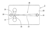
エジェクタユニット3には、エジェクタ25が形成されている。エジェクタ25は、図2に示すように、ノズル26の下流側にディフューザ27を配置してラバールノズルを形成し、ノズル26のスロート部28の下流に吸引口29を開口させたものであり、ノズル26の入口30からディフューザ27の出口通路31(出口)へ向かって気体を流すと、スロート部28に音速に達する高速噴流が生成される。この高速噴流により、吸引口29の気体が吸引されて、吸引口29からディフューザ27の出口通路31の負圧よりも真空度の高い負圧を得ることができる。エジェクタ25は、エジェクタユニット3のマニホールドユニット4との結合面に、凹部を設けて平板状に形成した2次元形状となっており、これにより、複雑な形状のエジェクタ25を高精度で容易に加工することが可能となる。
An
エジェクタユニット3には、気圧式倍力装置等の負圧作動装置(図示せず)に接続するための負圧供給口32が設けられており、負圧供給口32は、通路33によって逆止弁34、35をそれぞれ介して吸引口29及び出口通路31に連通されている。逆止弁34は、負圧供給口32側から吸引口29側への空気の流通のみを許容し、逆止弁35は、負圧供給口32側から出口通路31側への空気の流通のみを許容するものである。
The
マニホールドユニット4には、真空ポンプユニット2の第1及び第2吸込ポート12、18と、エジェクタユニット3の出口通路31とを連通させる吸込通路36が設けられている。また、マニホールドユニット4には、真空ポンプユニット2の第1及び第2吐出ポート14、20と、エジェクタユニット3の入口30とを連通させる吐出通路37が設けられている。この吐出通路37は、逆止弁38(第3逆止弁)を介して、大気に開放されており、逆止弁38は、吐出通路37側から大気側への空気の流通のみを許容する。
The
以上のように構成した本実施形態の作用について次に説明する。
通電により真空ポンプユニット2のコイル8を励磁すると、その磁界の作用によって、シリンダ5内のピストン6が往復動して、逆止弁15、22を介して第1及び第2吸込ポート12、18から空気を吸入し、逆止弁16、21を介して第1及び第2吐出ポート14、20から空気を吐出する。そして、マニホールドユニット4の吸込通路36を介して、エジェクタ25の出口通路31の空気を吸入し、また、吐出通路37を介してエジェクタ25の入口30に吐出空気を供給する。このとき、逆止弁38によって、吐出通路37が陽圧になるのを防止する。
Next, the operation of the present embodiment configured as described above will be described.
When the
これにより、ノズル26の入口30からディフューザ27の出口通路31への空気の流れが生じ、ラバールノズルを形成するノズル26及びディフューザ27の作用によって、スロート部28に音速に達する高速噴流が生じて、吸引口29にポンプユニット2の吸込負圧よりも高い真空度の負圧が生じる。この高い真空度の負圧を逆止弁34を介して、負圧供給口32から気圧式倍力装置等の負圧作動装置に供給する。
As a result, an air flow from the
このようにして、真空ポンプユニット2で発生させた負圧をエジェクタ25によって増強することができ、真空ポンプユニット2の負荷を軽減しつつ、気圧式倍力装置等の負圧作動装置に必要な高い真空度の負圧を供給することができる。このとき、真空ポンプユニット2によって−250mmHg乃至−300mmHg程度の負圧を発生させることにより、−500mmHg程度の負圧を供給することができる。その結果、真空ポンプユニット2の負荷が軽減されるので、真空ポンプの小型化が可能となり、また、吸込及び吐出による負荷変動が軽減されるので、真空ポンプの円滑な運転が可能になる。
In this way, the negative pressure generated by the
さらに、例えば、負圧供給装置1を自動車のブレーキの気圧式倍力装置に対して用いた場合に、ブレーキの連続的作動により、気圧式倍力装置の負圧が極端に低下したとき等においては、逆止弁35が開いて、真空ポンプユニット2の第1及び第2吸込ポート12、18によって、負圧供給口32の空気を直接吸込むことにより、吸込流量を増大させて、気圧式倍力装置の負圧を迅速に回復することができる。
Furthermore, for example, when the negative
次に、本発明の第2実施形態について、図4及び図5を参照して説明する。
なお、以下の説明において、上記第1実施形態に対して、対応する部分には同一の符号を付して、異なる部分についてのみ詳細に説明する。
Next, a second embodiment of the present invention will be described with reference to FIGS.
In the following description, the same reference numerals are assigned to the corresponding parts in the first embodiment, and only different parts will be described in detail.
図4及び図5に示すように、本実施形態に係る負圧供給装置39では、上記第1実施形態のマニホールドユニット4が省略されて、真空ポンプユニット2とエジェクタユニット3とが直接結合されている。そして、真空ポンプユニット2の第1及び第2吸込ポート11、18は、中空とされたロッド7内の通路40によって、互いに連通されて、エジェクタユニット3の出口通路31に直接連通されている。また、第1及び第2吐出ポート14、20は、直接、大気に開放されており、エジェクタユニット3の入口30は、第1吐出ポート14に連通されて、大気に開放されている。
As shown in FIGS. 4 and 5, in the negative
本実施形態における真空ポンプユニット2では、上記第1実施形態に対して、ピストン6が大径、短ストローク化されており、これにより、コイル8が2つのみ設けられている。また、ピストン6の大径化によって生じるスペースを利用して、吸込側の逆止弁15、22と、吐出側の逆止弁16、21とがピストン6の直径方向に沿って配置されており、これにより、逆止弁15、22及び逆止弁16、21の部品が共通化されている。
In the
このように構成したことにより、上記第1実施形態と同様、真空ポンプユニット2で発生させた負圧をエジェクタ25によって増強することができ、真空ポンプユニット2の負荷を軽減しつつ、気圧式倍力装置等の負圧作動装置に必要な高い真空度の負圧を供給することができる。なお、本実施形態では、エジェクタ25の入口30には、大気圧の空気が供給される。
また、上記第1実施形態に対して、マニホールドユニット4を省略し、逆止弁15、16、21、22の部品を共通化し、コイル8を2つのみとしたことにより、構造を簡素化して製造コストを低減することができる。
With this configuration, as in the first embodiment, the negative pressure generated by the
Further, compared to the first embodiment, the
なお、上記第1及び第2実施形態では、真空ポンプとして、往復動ピストン型のポンプを使用しているが、このほか、アキシャルピストンポンプ、ベーンポンプ、スクロールポンプ等の他形式のポンプを用いることも可能である。ポンプの駆動源としては、可動磁石型のリニアモータのほか、磁石が不要のリニアSRM(スイッチド レラクタンス モータ)等の他形式のリニアモータを使用することができ、また、回転型のポンプを使用する場合には、回転モータを使用することもできる。 In the first and second embodiments, a reciprocating piston type pump is used as the vacuum pump. However, other types of pumps such as an axial piston pump, a vane pump, a scroll pump, etc. may be used. Is possible. As a pump drive source, in addition to a movable magnet type linear motor, other types of linear motors such as a linear SRM (switched reluctance motor) that does not require a magnet can be used, and a rotary pump is used. In this case, a rotary motor can be used.
次に、本発明の第3実施形態について、図6を参照して説明する。なお、上記第1実施形態に対して、同様の部分には同一の符号を付して説明する。
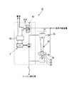
図6に示すように、本実施形態に係る負圧供給装置41は、上記第1実施形態と同様、エジェクタ25の吸引口29が逆止弁34を介して気圧式倍力装置等の負圧作動装置に接続され、出口通路31が真空ポンプユニット2の吸込口に接続され、かつ、逆止弁35を介して負圧作動装置に接続され、また、入口30が真空ポンプユニット2の吐出口に接続されている。そして、エジェクタ25の入口30及び真空ポンプユニット2の吐出口は、エンジン吸気管(スロットルバルブの下流側)に接続されている。
Next, a third embodiment of the present invention will be described with reference to FIG. In addition, the same code | symbol is attached | subjected and demonstrated with respect to the said 1st Embodiment.
As shown in FIG. 6, in the negative
真空ポンプユニット2を駆動する駆動回路42には、負圧作動装置(気圧式倍力装置の負圧室等)の負圧を検出する負圧スイッチ43が接続されており、負圧作動装置の真空度が所定レベルまで低下したとき、負圧スイッチ43がオンとなって、駆動回路42によって真空ポンプユニット2が駆動される。
The
以上のように構成した本実施形態の作用について次に説明する。
真空ポンプユニット2の停止中には、エンジン吸気管から、真空ポンプユニット2、エジェクタ25及び逆止弁34、35を介して、負圧作動装置に、エンジン吸気負圧が直接供給される。
Next, the operation of the present embodiment configured as described above will be described.
While the
真空ポンプユニット2を作動させると、真空ポンプユニット2の吸込口と吐出口と差圧によって、エジェクタ25の入口30から出口通路31への空気の流れが生じ、これによりエジェクタ25の吸引口29に真空ポンプユニット2の吸引負圧よりも高い真空度の負圧が生じ、この負圧が逆止弁34を介して負圧作動装置に供給される。このとき、真空ポンプユニット2の吐出側がエンジン吸気負圧によって吸引されるので、エジェクタ25の吸引口29に生じる負圧の真空度を高めると共に吸引流量を増大させることができ、また、真空ポンプユニット2の負担を軽減するこができる。
When the
負圧スイッチ43によって、負圧作動装置の真空度を監視し、真空度が充分高い場合には、負圧スイッチ43がオフとなり、真空ポンプユニット2が停止して、エンジン吸気負圧が負圧作動装置に直接供給される。負圧作動装置の負圧が所定レベルまで低下すると、負圧スイッチ43がオンとなって、真空ポンプユニット2が作動し、エジェクタ25の吸引口29から高い真空度の負圧を供給して、負圧作動装置の真空度を迅速に回復することができる。
The
このようにして、真空ポンプユニット2の吐出側をエンジン吸気負圧によって吸引し、必要に応じて真空ポンプユニット2の作動をオン、オフすることにより、真空ポンプユニット2の消費動力を低減しつつ、高い真空度の負圧を供給することができ、真空ポンプユニット2の小型化が可能となる。なお、真空ポンプユニット2の故障、エジェクタ25のスロート部28に目詰まりが生じた場合でも、エンジン吸気負圧が負圧作動装置に直接供給されるので、負圧作動装置の作動状態を維持することができる。
In this way, the suction side of the
次に、本発明の第4実施形態について、図7を参照して説明する。なお、上記第3実施形態に対して、同様の部分には同一の符号を付して、異なる部分についてのみ詳細に説明する。 Next, a fourth embodiment of the present invention will be described with reference to FIG. In addition, the same code | symbol is attached | subjected to the same part with respect to the said 3rd Embodiment, and only a different part is demonstrated in detail.
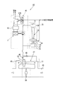
図7に示すように、本実施形態に係る負圧供給装置44では、エジェクタ25の入口30に接続された真空ポンプユニット2の吐出側は、逆止弁45、46及び第2エジェクタ47を介してエンジン吸気管48に接続されている。第2エジェクタ47は、上述のエジェクタ25と同様、ノズルとディフューザとを組合わせた構造であり、ディフューザの入口49がエンジン吸気管48のスロットルバルブ50の上流側に接続され、ディフューザの出口51がスロットルバルブ50の下流側に接続され、ノズルとディフューザとの間の吸引口52が逆止弁45を介して真空ポンプユニット2の吐出側に接続されている。また、第2エジェクタ47の出口51は、逆止弁46を介して、真空ポンプユニット2の吐出側に接続されている。逆止弁45及び46は、それぞれ真空ポンプユニット2の吐出側から第2エジェクタ47の吸引口52側及び出口51(エンジン吸気管48)側への流通のみを許容するものである。
As shown in FIG. 7, in the negative
このように構成したことにより、エンジン吸気管48のスロットルバルブ50の上流側と下流側との差圧によって、第2エジェクタ47の入口49から出口51へ空気の流れが生じ、これによって吸引口52に生じたエンジン吸気管48よりも高い真空度の負圧を真空ポンプユニット2の吐出側に供給することができ、負圧作動装置に供給する負圧の真空度を高めることができる。その結果、真空ポンプユニット2、エジェクタ25及び第2エジェクタ47を小型化することが可能となる。なお、車両の始動直後等、負圧作動装置の真空度が低く、真空ポンプユニット2の吐出側の真空度がエンジン吸気管48のスロットルバルブ50の下流側よりも低い場合には、逆止弁46が開いて、スロットルバルブ50の下流側の負圧が真空ポンプユニット2の吐出側に直接供給される。
With this configuration, an air flow is generated from the
また、真空ポンプユニット2の故障、エジェクタ25のスロート部28に目詰まりが生じた場合には、エジェクタ25は機能しなくなるが、第2エジェクタ47の吸引口52からエンジン吸気負圧よりも高い真空度の負圧を負圧作動装置に供給することができ、負圧作動装置の作動状態を維持することができる。
In addition, when the
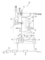
次に、本発明の第5実施形態について、図8を参照して説明する。なお、上記第4実施形態に対して、同様の部分には同一の符号を付して、異なる部分についてのみ詳細に説明する。 Next, a fifth embodiment of the present invention will be described with reference to FIG. In addition, the same code | symbol is attached | subjected to the same part with respect to the said 4th Embodiment, and only a different part is demonstrated in detail.
図8に示すように、本実施形態に係る負圧供給装置53は、ターボチャージャ等の過給機を備えたエンジンに装着されるものであり、エンジン吸気管48のスロットルバルブ50の上流側に過給機54及びインタークーラ55が設けられており、真空ポンプユニット2の吐出側に逆止弁56(第3逆止弁)が接続されている。逆止弁56は、真空ポンプユニット2の吐出側を大気に開放するためのものであり、真空ポンプユニット2の吐出側から大気側への流通のみを許容する。
As shown in FIG. 8, the negative
以上のように構成した本実施形態の作用について次に説明する。
エンジン回転数が高いとき、過給機54の過給圧によって、過給機54の下流側のエンジン吸気管48の内部(インタークーラ55、スロットルバルブ50の上流側及び下流側)が全て正圧となることがある。このような場合、この正圧が真空ポンプユニット2の吐出側に流入するのを逆止弁45、46によって防止し、また、真空ポンプユニット2の吐出側を逆止弁56によって大気に開放することにより、真空ポンプユニット2の吐出側が大気圧以上となって負圧作動装置に供給する負圧の真空度が過度に低下するのを防止することができる。これにより、過給機を備えたエンジンにおいても、負圧作動装置に安定した負圧を供給することができる。
Next, the operation of the present embodiment configured as described above will be described.
When the engine speed is high, all of the inside of the
なお、上記第3実施形態の負圧供給装置41についても、過給機を備えたエンジンに装着する場合には、上記第5実施形態の場合と同様、真空ポンプユニット2の吐出側を大気に開放する逆止弁を設けることにより、過給の影響によって真空ポンプユニット2の吐出側が正圧となるのを防止することができ、負圧作動装置に安定した負圧を供給することが可能となる。
In addition, when the negative
1 負圧供給装置、2 真空ポンプユニット(真空ポンプ)、12 第1吸込ポート(吸込口)、18 第2吸込ポート(吸込口)、25 エジェクタ、26 ノズル、27 ディフューザ、29 吸引口、31 出口通路(出口)、34,35 逆止弁
DESCRIPTION OF
Claims (5)
Priority Applications (1)
| Application Number | Priority Date | Filing Date | Title |
|---|---|---|---|
| JP2004286681A JP4385257B2 (en) | 2003-10-31 | 2004-09-30 | Negative pressure supply device |
Applications Claiming Priority (2)
| Application Number | Priority Date | Filing Date | Title |
|---|---|---|---|
| JP2003373259 | 2003-10-31 | ||
| JP2004286681A JP4385257B2 (en) | 2003-10-31 | 2004-09-30 | Negative pressure supply device |
Publications (3)
| Publication Number | Publication Date |
|---|---|
| JP2005155610A JP2005155610A (en) | 2005-06-16 |
| JP2005155610A5 JP2005155610A5 (en) | 2007-02-01 |
| JP4385257B2 true JP4385257B2 (en) | 2009-12-16 |
Family
ID=34741308
Family Applications (1)
| Application Number | Title | Priority Date | Filing Date |
|---|---|---|---|
| JP2004286681A Active JP4385257B2 (en) | 2003-10-31 | 2004-09-30 | Negative pressure supply device |
Country Status (1)
| Country | Link |
|---|---|
| JP (1) | JP4385257B2 (en) |
Families Citing this family (4)
| Publication number | Priority date | Publication date | Assignee | Title |
|---|---|---|---|---|
| JP2007223449A (en) * | 2006-02-23 | 2007-09-06 | Advics:Kk | Vehicular brake device |
| JP4187000B2 (en) * | 2006-04-07 | 2008-11-26 | トヨタ自動車株式会社 | Ejector system for vehicle and control device |
| JP2014084052A (en) | 2012-10-26 | 2014-05-12 | Aisan Ind Co Ltd | Negative pressure supply unit |
| DE102013218060A1 (en) * | 2012-12-06 | 2014-06-12 | Robert Bosch Gmbh | Linear drive and piston pump arrangement |
-
2004
- 2004-09-30 JP JP2004286681A patent/JP4385257B2/en active Active
Also Published As
| Publication number | Publication date |
|---|---|
| JP2005155610A (en) | 2005-06-16 |
Similar Documents
| Publication | Publication Date | Title |
|---|---|---|
| EP2199566B1 (en) | Two-stage exhaust turbocharger | |
| EP1806503B1 (en) | Booster-type gas compressor | |
| CN107135659B (en) | Multi-stage jet type suction pump | |
| KR20170088860A (en) | Evacuator system for supplying high suction vacuum or high suction flow rate | |
| JP4385257B2 (en) | Negative pressure supply device | |
| KR20160073976A (en) | Axial compressor with a magnetic stepper or servo motor | |
| US7591636B2 (en) | Negative pressure supply apparatus | |
| JP2007137409A (en) | Pump for braking system | |
| EP1234982B1 (en) | Vacuum pump | |
| JP2002257099A (en) | Vacuum producing device | |
| JP6052699B1 (en) | Supercharger for internal combustion engine | |
| KR20230032221A (en) | Cylinder type NVH vacuum pump for vehicle | |
| JP2000265951A (en) | Pneumatic vacuum pump | |
| JP2006037868A (en) | Negative pressure feeder | |
| KR20210145635A (en) | Fuel pump for liquid fuel water injection system of motor vehicle | |
| CN109154293A (en) | Motor vehicle vacuum pump apparatus | |
| KR100462744B1 (en) | Vacuum pump for vehicle | |
| JP4869799B2 (en) | Idle air flow control device | |
| KR20160030312A (en) | Aspirator and ejector system | |
| JP2001073953A (en) | Pump | |
| JP4156102B2 (en) | Pressure actuator | |
| JPH10246184A (en) | Load reducing device for air compressor | |
| KR101362205B1 (en) | Air blower for fuel cell vehicle | |
| JP4196070B2 (en) | Vane rotary air pump | |
| WO2006027848A1 (en) | Multistage piston type vacuum pump |
Legal Events
| Date | Code | Title | Description |
|---|---|---|---|
| A521 | Written amendment |
Free format text: JAPANESE INTERMEDIATE CODE: A523 Effective date: 20061208 |
|
| A621 | Written request for application examination |
Free format text: JAPANESE INTERMEDIATE CODE: A621 Effective date: 20061208 |
|
| A977 | Report on retrieval |
Free format text: JAPANESE INTERMEDIATE CODE: A971007 Effective date: 20090304 |
|
| A131 | Notification of reasons for refusal |
Free format text: JAPANESE INTERMEDIATE CODE: A131 Effective date: 20090325 |
|
| A521 | Written amendment |
Free format text: JAPANESE INTERMEDIATE CODE: A523 Effective date: 20090521 |
|
| A711 | Notification of change in applicant |
Free format text: JAPANESE INTERMEDIATE CODE: A712 Effective date: 20090902 |
|
| RD03 | Notification of appointment of power of attorney |
Free format text: JAPANESE INTERMEDIATE CODE: A7423 Effective date: 20090902 |
|
| TRDD | Decision of grant or rejection written | ||
| A521 | Written amendment |
Free format text: JAPANESE INTERMEDIATE CODE: A523 Effective date: 20090904 |
|
| A01 | Written decision to grant a patent or to grant a registration (utility model) |
Free format text: JAPANESE INTERMEDIATE CODE: A01 Effective date: 20090909 |
|
| A01 | Written decision to grant a patent or to grant a registration (utility model) |
Free format text: JAPANESE INTERMEDIATE CODE: A01 |
|
| A61 | First payment of annual fees (during grant procedure) |
Free format text: JAPANESE INTERMEDIATE CODE: A61 Effective date: 20090915 |
|
| R150 | Certificate of patent or registration of utility model |
Free format text: JAPANESE INTERMEDIATE CODE: R150 |
|
| FPAY | Renewal fee payment (event date is renewal date of database) |
Free format text: PAYMENT UNTIL: 20121009 Year of fee payment: 3 |