JP4383349B2 - Multi-axis cross-connect system for spinal implants - Google Patents
Multi-axis cross-connect system for spinal implants Download PDFInfo
- Publication number
- JP4383349B2 JP4383349B2 JP2004548517A JP2004548517A JP4383349B2 JP 4383349 B2 JP4383349 B2 JP 4383349B2 JP 2004548517 A JP2004548517 A JP 2004548517A JP 2004548517 A JP2004548517 A JP 2004548517A JP 4383349 B2 JP4383349 B2 JP 4383349B2
- Authority
- JP
- Japan
- Prior art keywords
- shaft
- hook
- opening
- spinal
- coupling member
- Prior art date
- Legal status (The legal status is an assumption and is not a legal conclusion. Google has not performed a legal analysis and makes no representation as to the accuracy of the status listed.)
- Expired - Fee Related
Links
Images


Classifications
-
- A—HUMAN NECESSITIES
- A61—MEDICAL OR VETERINARY SCIENCE; HYGIENE
- A61B—DIAGNOSIS; SURGERY; IDENTIFICATION
- A61B17/00—Surgical instruments, devices or methods, e.g. tourniquets
- A61B17/56—Surgical instruments or methods for treatment of bones or joints; Devices specially adapted therefor
- A61B17/58—Surgical instruments or methods for treatment of bones or joints; Devices specially adapted therefor for osteosynthesis, e.g. bone plates, screws, setting implements or the like
- A61B17/68—Internal fixation devices, including fasteners and spinal fixators, even if a part thereof projects from the skin
- A61B17/70—Spinal positioners or stabilisers ; Bone stabilisers comprising fluid filler in an implant
- A61B17/7049—Connectors, not bearing on the vertebrae, for linking longitudinal elements together
- A61B17/7052—Connectors, not bearing on the vertebrae, for linking longitudinal elements together of variable angle or length
Landscapes
- Health & Medical Sciences (AREA)
- Orthopedic Medicine & Surgery (AREA)
- Life Sciences & Earth Sciences (AREA)
- Neurology (AREA)
- Surgery (AREA)
- Heart & Thoracic Surgery (AREA)
- Engineering & Computer Science (AREA)
- Biomedical Technology (AREA)
- Nuclear Medicine, Radiotherapy & Molecular Imaging (AREA)
- Medical Informatics (AREA)
- Molecular Biology (AREA)
- Animal Behavior & Ethology (AREA)
- General Health & Medical Sciences (AREA)
- Public Health (AREA)
- Veterinary Medicine (AREA)
- Prostheses (AREA)
- Surgical Instruments (AREA)
Description
一般に、本発明は脊椎異常を矯正するためのシステムおよび構成部品に関する。より詳細には、本発明は脊椎変形を治療し矯正する脊椎ロッドおよび脊椎ロッド相互連結組立体を含む脊椎固定システムを対象とする。 In general, the present invention relates to systems and components for correcting spinal abnormalities. More particularly, the present invention is directed to a spinal fixation system that includes a spinal rod and a spinal rod interconnect assembly for treating and correcting spinal deformities.
本出願は、参照によってその全体を援用する2002年10月28日出願の米国特許仮出願第60/421,701号の利益を主張する。
脊椎固定システムは、様々な問題点に対処するために外科手術中に埋め込まれる。こうした処置には、例えば脊柱側湾症、脊椎すべり症、脊椎後湾症、脊椎前湾症、関節症など先天的脊椎変形の矯正、脊椎損傷の修復、および先天的状態を安定化し、かつ/または慢性的腰痛を緩和するための椎骨の癒合などがある。脊椎を矯正し安定化し、脊椎の癒合を促進するためのいくつかの手技およびシステムが開発されてきた。
This application claims the benefit of US Provisional Application No. 60 / 421,701, filed Oct. 28, 2002, which is incorporated by reference in its entirety.
Spinal fixation systems are implanted during surgery to address various issues. Such treatments include, for example, correction of congenital spinal deformities such as scoliosis, spondylolisthesis, kyphosis, prespondylosis, arthropathy, repair of spinal injury, and stabilization of congenital conditions, and / or Or vertebral fusion to relieve chronic low back pain. Several procedures and systems have been developed to correct and stabilize the spine and promote fusion of the spine.
1つの一般的なシステムでは、屈曲可能なロッドや脊椎ロッドなどの長手方向部材が、脊柱に沿って配設され、任意の数の固定要素によって脊柱の長さに沿って様々な椎骨に選択された箇所で固定される。様々な脊椎固定要素が知られており、フックや骨ねじなどが挙げられる。これらの固定要素は、椎骨の特定の部分に係合し取り付けられる形状になっている。通常、外科医は椎骨固定要素を解剖学的に適切な位置で脊椎に取り付け、各脊椎固定要素を脊椎ロッドに取り付ける。それとともに、外科医は脊柱および/または個々の椎骨の向きを変え、かつ/または再整列させて、脊椎異常に対する所望の治療を施す。その結果、脊椎ロッドを脊柱に沿って互いに非平行に屈曲させ、あるいは向きを定めることができる。 In one common system, longitudinal members, such as bendable and spinal rods, are disposed along the spinal column and are selected for various vertebrae along the length of the spinal column by any number of fixation elements. It is fixed at the spot. Various spinal fixation elements are known, including hooks and bone screws. These fixation elements are configured to engage and attach to specific portions of the vertebra. Typically, the surgeon attaches vertebral fixation elements to the spine at an anatomically appropriate location and attaches each spinal fixation element to the spinal rod. At the same time, the surgeon redirects and / or realigns the spine and / or individual vertebrae to provide the desired treatment for spinal abnormalities. As a result, the spinal rods can be bent or oriented non-parallel to each other along the spinal column.
脊椎ロッドは一般に、ちょうど支持体の間に横木が並んでいる梯子のように、互いに連結されて、より堅固な支持およびアラインメントシステムを提供する。交差連結部材は脊椎ロッドの様々な向きに対応しなければならない。さらに連結部材は、例えば、脊髄および/または脊柱に関連または隣接する脊椎突起など、構造物または神経と干渉せずに、脊椎ロッド間の間隙を埋めることができなければならない。さらに、連結部材は脊椎ロッドを堅固かつ確実に相互連結しなければならない。明らかに、システムの不具合および脊椎ロッドおよび関連する構成部品のずれは、患者に大きな苦痛をもたらし、是正のための追加の外科手術が必要になる可能性がある。調整可能でしかも堅固な交差連結器は、脊椎異常の治療を容易にする。 Spinal rods are generally connected together, just like a ladder with rungs lined between supports, to provide a more robust support and alignment system. The cross-connecting member must accommodate various orientations of the spinal rod. In addition, the connecting member must be able to fill the gap between the spinal rods without interfering with structures or nerves, such as spinal processes associated with or adjacent to the spinal cord and / or spinal column. Furthermore, the connecting member must interconnect the spinal rods firmly and securely. Obviously, system malfunctions and misalignment of the spinal rod and related components can cause great distress to the patient and may require additional surgery to correct. An adjustable and robust cross-connector facilitates treatment of spinal abnormalities.
本質的に、どのような外科手術も細心の注意を要する治療である。脊柱付近での手術は、より一層の細心の注意を要し、難易度が高い。予想される外科手術に加えて、外科医は脊柱および椎骨を整列させなければならない。この処置の間、またはその直後に、外科医は固定要素を位置決めし、脊椎ロッドシステムを組み立て、脊椎ロッドシステムを椎骨に固定し、次いでシステム全体の連結部を固締してそれ以上動かないようにしなければならない。脊椎ロッドシステムの組立ては非常に困難になることがあり、構成部品が体液で覆われている場合は特にそうである。手術室で迅速かつ確実に組み立てることのできる、より「ユーザにとって使いやすい」脊椎固定システムがあれば、外科医にとっても患者にとっても多大な利益となるであろう。 In essence, any surgical procedure is a sensitive treatment. Surgery near the spine requires more attention and is more difficult. In addition to the anticipated surgery, the surgeon must align the spine and vertebrae. During or immediately after this procedure, the surgeon positions the fixation element, assembles the spinal rod system, secures the spinal rod system to the vertebra, and then secures the entire system connection to prevent further movement. There must be. Assembling the spinal rod system can be very difficult, especially when the components are covered with bodily fluids. A more “user-friendly” spinal fixation system that can be assembled quickly and reliably in the operating room would be of great benefit to both the surgeon and the patient.
したがって、上述の問題点に照らして、改善された脊椎固定組立体、関連構成部品、および脊椎異常の治療方法を含む関連分野では、引き続き改良の必要がある。本発明はそのような改良の1つであり、多種多様な利益および利点を提供する。 Accordingly, in light of the above-mentioned problems, there is a continuing need for improvements in related fields, including improved spinal fixation assemblies, related components, and methods for treating spinal abnormalities. The present invention is one such improvement and provides a wide variety of benefits and advantages.
一般に、本発明は脊椎異常の治療のための組立体および装置を提供する。組立体は、脊椎ロッドなどの細長い部材、細長い部材を個々の椎体上の解剖学的位置に固定する骨締結具、および細長い部材を相互連結する相互連結器を含むことができる。 In general, the present invention provides assemblies and devices for the treatment of spinal abnormalities. The assembly can include an elongated member, such as a spinal rod, a bone fastener that secures the elongated member to an anatomical location on an individual vertebral body, and an interconnector that interconnects the elongated members.
一形態では、本発明は第1の脊椎ロッド連結器、第2の脊椎ロッド連結器、および2つの脊椎ロッド連結器を互いに選択された向きで固定する相互連結要素を含む相互連結組立体を提供する。第1および第2脊椎ロッド連結器は、脊柱により大きな間隙をもたらすように、湾曲したシャフトで形成することができる。相互連結要素はボディを含むことができる。該ボディは、開口とボディから突き出たねじ付きスタッドとを有する。一形態では、相互連結要素は、片方または両方のロッド連結器の一部がその中を貫いて延びることのできる開口を備えたアイボルトとして設けることができる。締結具は、第1および第2の細長い部材を互いに所望の向きで確実にロックさせるように、ボディから突き出たスタッドに対して固定することができる。 In one form, the present invention provides an interconnection assembly that includes a first spinal rod coupler, a second spinal rod coupler, and an interconnection element that secures the two spinal rod couplers in a selected orientation relative to each other. To do. The first and second spinal rod couplers can be formed with curved shafts to provide a larger gap in the spinal column. The interconnection element can include a body. The body has an opening and a threaded stud protruding from the body. In one form, the interconnection element can be provided as an eyebolt with an opening through which a portion of one or both rod connectors can extend. The fastener can be secured to a stud protruding from the body to ensure that the first and second elongated members are locked together in the desired orientation.
他の形態では、本発明は、第1シャフト、第2シャフト、および複数の締結具を含む相互連結部材を提供する。第2シャフトは、その終端部に相互連結ボディを担持することができる。相互連結ボディは、第1連結器に対して第1シャフトの一部を受ける開口を含むことができる。第1脊椎ロッド連結器を第2脊椎ロッド連結器に対して所望の向きでロックするように、締結具の1つをボディに固定することができる。 In another form, the present invention provides an interconnect member that includes a first shaft, a second shaft, and a plurality of fasteners. The second shaft can carry an interconnection body at its end. The interconnecting body can include an opening that receives a portion of the first shaft relative to the first connector. One of the fasteners can be secured to the body to lock the first spinal rod coupler in a desired orientation relative to the second spinal rod coupler.
さらに別の形態では、本発明は、2つの脊椎ロッド連結部材を相互連結できる多軸可変相互連結器を提供する。一実施形態では、多軸脊椎ロッド連結器は球関節を含む。
他の形態では、相互連結要素はアイボルトとして設けることができる。アイボルトは、中を貫く開口を有するボディ、上面、および上面から突き出たスタッドを含む。さらに上面は、スタッド周りに配置された複数の径方向スプラインを含むことができる。あるいは、上面に複数の径方向スプラインを備えた座金を、内部のスタッドの周りに設けることもできる。どちらの形態でも、第2脊椎ロッド連結部材は、スタッド周りのスプラインに対合的に係合する形状のスプラインを有する下面を含むことができる。スプラインを噛み合わせ、それによって第1脊椎ロッド連結器を第2脊椎ロッド連結器に対して所望の向きでロックするように、締結具をスタッドに対して固定することができる。
In yet another form, the present invention provides a multi-axis variable interconnector that can interconnect two spinal rod connecting members. In one embodiment, the polyaxial spinal rod connector includes a ball joint.
In other forms, the interconnection elements can be provided as eyebolts. The eyebolt includes a body having an opening therethrough, a top surface, and a stud protruding from the top surface. Further, the top surface can include a plurality of radial splines disposed about the stud. Alternatively, a washer with a plurality of radial splines on the top surface can be provided around the internal stud. In either configuration, the second spinal rod coupling member can include a lower surface having a spline shaped to matingly engage the spline about the stud. The fastener can be secured to the stud so as to engage the spline and thereby lock the first spinal rod connector relative to the second spinal rod connector in the desired orientation.
さらに他の形態では、本発明は脊椎ロッドをフック内で固定することのできる脊椎ロッド連結部材を提供する。フックは、フックの湾曲部または凹部内にサドルまたはリッジ部を含むことができる。リッジまたはサドル部によって、脊椎ロッドをフック内に様々な向きで設置することが可能になる。さらに、脊椎ロッド連結部材は、脊椎ロッドをフック内に固定するために、ねじ付き開口およびその中に受け入れられる締結具を含むことができる。 In yet another form, the present invention provides a spinal rod coupling member that can secure a spinal rod within a hook. The hook can include a saddle or ridge portion within the curved portion or recess of the hook. The ridge or saddle allows the spinal rod to be placed in various orientations within the hook. Further, the spinal rod coupling member can include a threaded opening and a fastener received therein to secure the spinal rod within the hook.
さらに他の形態では、本発明はあらかじめ組立て済みの相互連結組立体を提供する。あらかじめ組立て済みの相互連結組立体は、第1および第2脊椎ロッド連結部材の限定的な動きを維持する。第1および第2脊椎ロッド連結部材の限定的な動きによって、非平行な脊椎ロッドを固定するための、相互連結部材の展開、および/または第2脊椎ロッド連結部材に対する1つの脊椎ロッド連結部材の回転が可能になる。この限定的な動きはまた、相互連結組立体が不注意によって分解されるのを防ぐこともできる。さらに連結要素は、長手方向に延びる1対の脊椎ロッドと脊柱を堅固に固定しながら、脊柱後方に位置する様々な骨および神経構造物、突起との接触を最小限にする、または排除する形状とすることができる。 In yet another form, the present invention provides a pre-assembled interconnection assembly. The pre-assembled interconnection assembly maintains limited movement of the first and second spinal rod connection members. Deployment of the interconnecting member to secure the non-parallel spinal rod and / or of one spinal rod connecting member relative to the second spinal rod connecting member by limited movement of the first and second spinal rod connecting members Rotation is possible. This limited movement can also prevent the interconnect assembly from being inadvertently disassembled. In addition, the connecting element is configured to minimize or eliminate contact with various bone and neural structures and processes located behind the spinal column while firmly fixing the pair of longitudinally extending spinal rods and spinal column It can be.
本発明のその他の目的、特徴、形態、および利点は、本明細書に含まれる以下の説明および図面から明らかになるであろう。 Other objects, features, forms and advantages of the present invention will become apparent from the following description and drawings contained herein.
本発明の原理を理解しやすくするため、ここでは本明細書に例示される実施形態を参照し、これを説明するために特定の用語を使用する。しかしながら、それによって本発明の範囲が限定されるものではないことを理解されたい。説明されたシステム、連結部品、および方法について、当業者なら通常思いつくはずのあらゆる改変および他の修正、ならびに本明細書で説明された本発明の原理のあらゆる他の応用例が企図されている。 In order to facilitate understanding of the principles of the invention, reference will now be made to the embodiments illustrated herein, and specific language will be used to describe the same. However, it should be understood that this does not limit the scope of the invention. Any variations and other modifications that would normally occur to those of ordinary skill in the art, and any other applications of the principles of the invention described herein are contemplated for the described systems, coupling components, and methods.
図1は、本発明による連結組立体10の一実施形態の分解斜視図である。連結組立体10は、雄型連結部材12、雌型連結部材14、相互連結要素16、および締結具18を含む。雄型連結部材12は、近位端22、反対側の遠位端24、それらの間のシャフト26を含む。近位端22は、円形または楕円形の断面を示すように設けられている。好ましい実施形態では、近位端22から隆起または突起28が突き出ている。例示された実施形態では、突起28は、長手方向軸に対してほぼ直角に、またはシャフト26によって規定される方向に、カムまたは円形突出部として設けられる。代替実施形態では、突起28を、シャフト26から直角にまたは斜めに突き出る単一または複数のフィンガまたはスプラインとして設けることもできる。
FIG. 1 is an exploded perspective view of one embodiment of a
シャフト26は、円筒形のシャフトとして設けられるが、所望のどのような形状で設けることもできることを理解されたい。例えば、シャフト26は長楕円、長方形、または三角形の断面を備えることができる。シャフト26は、長手方向軸を規定するほぼまっすぐな細長い部材として示されている。他の実施形態では、シャフト26をアーチ形のまたは湾曲したシャフトとして形成することもできる。シャフト26は、この遠位端24でロッド連結部32を担持する。どの実施形態においても、シャフト26は比較的滑らかな外側を有することができ、あるいは、その外側を粗くするまたはローレット切りすることもできる。
The
シャフト26は、脊椎ロッドまたは他の細長い部材、あるいは骨締結具に係合する形状のロッド連結部32内で終端する。好ましい実施形態では、ロッド連結部32は、所望のチャネル、陥凹部またはフックを備え、それぞれ脊椎ロッドを少なくとも部分的に取り囲むように適合され形成される。
The
さらに、部材を脊椎ロッドまたは骨締結具に固定するために、雌ねじ付きの開口34または穴を雄型連結部材12内にねじ切りすることができる。開口34は遠位端24内で好ましくはシャフト26を貫き、または遠位端24内でフックの内部へと延びる。開口34は、シャフト26によって規定される長手方向軸に対して直角または傾斜角のいずれかで、シャフト26内に形成することができる。例えば、開口34は、ロッド連結部32の外面からロッド連結部32の内部湾曲またはフックの近位側の内側面へと延びることができる。収容された脊椎ロッドを雄型連結部材12に固定するために、ねじ付き締結具36を開口34内にねじ込み式に受け入れることができる。ねじ付き締結具の例が、参照によってその全体を援用する米国特許第5,947,966号および第6,193,719号に示されている。締結具36は鈍いまたは凹形の先端を含むことができる。あるいは、締結具36は収容された脊椎ロッド(図示せず)の一部に係合し噛み合う歯および/または刃先を有する先端を含むことができる。
Further, an internally threaded opening 34 or hole can be threaded into the male coupling member 12 to secure the member to the spinal rod or bone fastener. The opening 34 preferably extends through the
好ましい実施形態では、雄型連結部材12は、特定の応用例または使用向けに選択された好ましい長さを有するように設けられる。一実施形態では、シャフト26によって規定される長手方向軸に沿って測定した好ましい長さは、約20mmから約46mmの間である。
In a preferred embodiment, the male coupling member 12 is provided to have a preferred length selected for a particular application or use. In one embodiment, the preferred length measured along the longitudinal axis defined by the
相互連結要素16は、アイボルト44として示されている。アイボルト44は円筒形または円形のボディ54を貫いて延びる開口46を含む。開口46は、その中を通る連結部材12などの連結部材から延びたシャフトの一部を受け入れるように設けられる。例示された実施形態では、開口46は長楕円形または楕円形の開口として形成される。好ましくは、開口46は、雄型連結部材12の突起28を含む近位端22を対合的に受け入れるように設けられる。相互連結要素16はまた、開口46によって規定される軸53に対してほぼ直角にボディ54から突き出たねじ付きスタッド52も含む。
The interconnecting
一実施形態では、インターロック部材56がボディ54とねじ付きスタッド52との間に配設される。例示された実施形態では、インターロック部材56は、周方向にボディ54周りで直径方向に互いに反対側に突き出ている1対のフランジまたは棚58および60を含む。フランジまたは棚58と60の間には、例えば棚部58および60に比べて頭部が切断された1対のランドまたは切頭部62および64が配設される。切頭部62および64はボディ54の側面とほぼ同一平面に形成することができる。棚58および60はスエージロック機構の一部として設けられ、相互連結要素16を雌型連結部材14と相互係合させる。
In one embodiment, an
別の実施形態では、ねじ付きスタッド52は、インターロック部材56を介在させずにアイボルト44から直接突き出ている。
雌型連結部材14は雄型連結部材12の相手方部分として設けられる。連結部材14は近位端78、遠位側脊椎ロッド係合部80、およびそれらの間のシャフト82を含む。シャフト82は比較的滑らかな外側を有することができ、あるいは、外側を粗くするまたはローレット切りすることもできる。脊椎ロッド係合部80は、雄型連結部材12のロッド連結部32について述べたのとほぼ同様に設けることができる。好ましい実施形態では、ロッド連結部32は、所望のチャネル、陥凹部またはフックを備え、それぞれが脊椎ロッドを少なくとも部分的に取り囲むように適合され形成される。さらに、開口85は、開口34と同様に、部材14を貫いて直角にあるいは傾斜して延びるように設けることができる。好ましくは開口85は、ねじ付き締結具がロッド係合部80のフックまたは湾曲内に設置された脊椎ロッドの外面に係合することを可能にする。締結具86などの締結具は、ロッド係合部80内で脊椎ロッドを固定するために開口85を通してねじ込み式に係合させることができる。
In another embodiment, the threaded
The
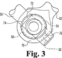
雌型連結部材14は、中を貫く開口72を有するボディ70を含む。一形態では、ボディ70はほぼ円形または楕円形の形状である。他の形態では、ボディ70は例えば立体や台形など、所望の通りに設けることができる。開口72は、その中にスタッド52を摺動可能に受け入れる形状になっている。好ましい実施形態では、開口72はスタッド52の雄ねじの外径よりも大きい内径を有する形状である。その結果、好ましい実施形態では、開口72の内面はねじ切りのない滑らかな穴となっている。別の実施形態では、開口72の内面はねじ切り穴とすることもできる。さらに別の実施形態では、開口72の内面は、1対の内棚74および76を含む。好ましくは、棚74および76は、ボディ70の下面75付近で直径方向に互いに反対側に配置される。棚74および76は、インターロック部材56および/または棚58および60と相互係合する形状になっており、雌型連結部材14をインターロック部材56に対して固定する(例えば図3を参照)。さらに他の実施形態では、開口72は、雌ねじまたは内棚を使用しない滑らかな穴として設けることもできる。締結具86は、締結具36について述べたのとほぼ同様に設けることができる。
The
好ましい実施形態では、雌型連結部材14は、適切に選択された所望の長さを有するように設けることができ、部材12とともに2つの脊椎ロッドを互いに固定できるようになっている。好ましい実施形態では、連結部材14は、シャフト82によって規定される長手方向軸に沿って測定した長さが約10mmから約65mmの間であるように設けることができる。
In a preferred embodiment, the
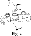
さらに図2から図5を参照すると、使用の際、雄型連結部材12の近位端22は開口46内に受け入れられ、近位端22および突起28が相互連結部材16の反対側から突き出るまで貫通する。突起28はこのように係合すると、図2に示すようにアイボルト44の、雄型連結部材12の遠位端24とは反対側に配設される。雄型連結部材12が長手方向軸周りで回転することにより、図4に示すように突起28が要素16の外面に接触し、アイボルトの下面81に隣接して配置される。可変角連結をもたらすために、雄型連結部材12は180度より小さいまたは大きい量だけ回転させることができることを理解されたい。次いで、雌型連結部材14がスタッド52の上に配置され、図3に示すように棚74および76は切頭部62および64の近位側になる。このとき雌型連結部材14がスタッド52周りで回転することにより、棚74および76が棚58および60に係合される。それによって、連結要素16は(逆回転させなくとも)スタッド52から不注意で外れたり脱落したりしないようになる。脊椎ロッドを固定し治療を容易にするために、雌型連結部材14は、雄型連結部材12および/または相互結合要素16に対して所望のどのような角度に調整することもできることを理解されたい。その後、図5に示すように、雄型連結部材12および雌型連結部材14を所望の向きで固定するために、締結具18をスタッド52に係合させることができる。
With further reference to FIGS. 2-5, in use, the
一実施形態では、締結具18はスタッド52の雄ねじに係合する雌ねじを含む。さらに、締結具18は陥凹部または印刻部と係合する内部の器具とともに止めねじとして設けることもできる。この実施形態では、開口72の少なくとも一部は、その中に締結具18の一部または全部を受け入れるのに十分な直径を有する。この実施形態では、埋込み部位から後方に突き出る、組立て済みの連結器の断面を最小限にすることができる。さらに、開口72の内穴は、締結具18の対応(対合)部分を支えそれに接触する段または溝を含むことができる。その結果、スタッド52上のねじ付き締結具18は、雌型連結部材14のボディ70をアイボルト44上に押し付け、ボディ70の下面81がシャフト26および/または突起28の一部と接触するようになる。締結具18をスタッド52に固定することによって、突起28がボディ70の一部に張り出すようになり、その結果、雄型連結部材12のシャフト26が引き抜かれるのを防ぐ。他の実施形態では、締結具18は、その外周に突き出るリップ67を含む。締結具18がスタッド52上に嵌まるとき、リップ67はボディ70の上面83と接触し、ボディ70をシャフトおよび/または突起28に同様に摩擦係合させる。この実施形態の一形態では、締結具18を円形の頂部を有するキャップとして設けることもできる。どちらの実施形態でも、雄型連結部材12および相互連結要素16は、互いに所望の向きでロックされ固定される。
In one embodiment,
本発明では、様々な締結具18を使用することができる。例えば、「破断式止めねじ(break off set screw)」と呼ばれる1つの締結具は、十分なトルクが加わると締結具18の一部が破断または剪断されるように弱体化した部分を含むことができる。このような破断式止めねじの例が、Gournay他に発行された米国特許第6,478,795号に開示されており、参照によってこれを援用する。
In the present invention,
図6Aは、本発明で使用される締結具30の別の例示的な実施形態である。締結具30は駆動器具を受け入れる形状の印刻部を含む。印刻部の形状は、所望のサイズにした六角頭印刻部、4面印刻部、「トルク」印刻部など所望の通りに設けることができる。
FIG. 6A is another exemplary embodiment of a
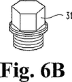
図6Bは、本発明で使用される締結具31のさらに別の実施形態である。締結具31は、6面ソケットなどの駆動器具によって把持される形状の頭部を含む。締結具18、30、および31のいずれも、アイボルトから突き出たスタッドに係合する雌ねじまたは雄ねじを含むことができる。
FIG. 6B is still another embodiment of the
連結組立体10は、組立て済みの、ただし緩く連結されたユニットとして、製造業者から提供され得ることを理解されたい。このように提供されると、不注意によって構成部品が互いに分離することがない。一形態では、図5に示すように、スタッド52の内部は内穴88を含み、締結具18は貫通穴を含む。製造中、締結具18を取り付けた後でダム(図示せず)が内穴88内に挿入される。次いでダムは、締結具18がねじ付きスタッド52から後退しないように、内穴88の端部66を拡げることができる。このことにより、雄型連結部材12、雌型連結部材14、および相互連結要素16を含む組立体が不注意によって分離するのを防止する。
It should be understood that the
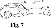
図7は、雄型連結部材94の代替実施形態の斜視図である。雄型連結部材94は雄型連結部材12について述べたのとほぼ同様に設けられる。ただし、雄型連結部材94は、アーチ形または湾曲したシャフト96を含む。部材94は、結果的に得られる連結組立体と脊柱後方の脊椎突起とが接触しないように、選択されたアーチ形または湾曲した形の側断面を備えることができる(例えば図9を参照)。
FIG. 7 is a perspective view of an alternative embodiment of the male coupling member 94. The male connection member 94 is provided in substantially the same manner as described for the male connection member 12. However, the male connection member 94 includes an arcuate or
さらに、連結部材94は、その中をシャフト96中に対して傾斜した角度で延びるねじ付き開口95を含む。
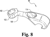
図8は、雌型連結部材14と同様の雌型連結部材98の斜視図である。連結部材98は湾曲したシャフト100を含む。シャフト100は、結果として得られる連結組立体と脊椎突起が脊柱後方で接触しないまたは接触を最小限に抑えるように、選択されたアーチ形または湾曲した形状を有するように形成することができる。さらに、シャフト100はシャフト96の湾曲とほぼ同等の湾曲を備えることができる。
Further, the connecting member 94 includes a threaded
FIG. 8 is a perspective view of a
雌型連結部材98は、中を貫く開口102を有するボディ103を含む。開口102は、アイボルト44上のスタッド52のようなスタッドを受け入れるサイズおよび形状になっている。図7に示す実施形態では、開口102はねじ切り部またはインターロック棚などのないほぼ滑らかな穴として設けられる。さらに部材98は、雄型連結部材94の開口95について上述したのと同様に設けられるねじ付き穴114を含む。
The
図9は、連結組立体110の斜視図である。組立体110は、雄型連結部材94、雌型連結部材98、および締結具18によって固定される相互連結要素16を含む。例示された実施形態では、雄型連結部材94および雌型連結部材98は、それぞれのシャフトに沿って同一のまたはほぼ同様の湾曲断面を示すように形成される。さらに、雌型連結部材98のシャフトによって規定される長手方向軸に沿って測定した組立体110全体の長さは、シャフト96をアイボルト112を通ってさらに摺動させ、またはアイボルト112から引き抜くように反対方向に摺動させることにより、可変とすることができる。締結具18を緩めることによって、雄型連結部材94のシャフト96を、相互連結要素16内の開口46を通って摺動させることができる。その結果、連結組立体110全体の長さを変化させて、雄型連結部材および雌型連結部材の遠位端が椎骨の横突起付近に配置された脊椎ロッドを把持できるようにする。連結組立体110は、雄型連結部材94または雌型連結部材98のどちらかと脊椎突起との接触を最小限にするのに十分な、基準線97に沿って測定した深さを有することができる。図10は、本発明による雌型連結部材120の別の実施形態の斜視図である。雌型連結部材120は、雌型連結部材14または連結部材98と同様に形成される。連結部材120は、ロッド固定部分124を規定する遠位端122、近位端126、およびそれらの間のシャフト132を含む。近位端126は、中を貫く開口130を備えたボディ128を担持する。ボディ128は、開口130周りで周方向に配置された多数の径方向スプライン、または交互に配置されるリッジ136および溝137を有する下面134を含む。リッジ136および溝137は、雌型連結部材120を所望の向きで固定またはロックしやすくするために備えられる。
FIG. 9 is a perspective view of the coupling assembly 110. The assembly 110 includes an
シャフト132は、遠位端122と近位端126との間に配設される。例示された実施形態では、シャフト132は、雌型連結部材98のシャフト100と同様のアーチ形のシャフトとして設けられる。他の実施形態では、シャフト132は図1に示すシャフト82のようにまっすぐなシャフトとして設けることもできる。さらにシャフト132は、円形、楕円形、長方形など、所望のどのような断面形状を有するように設けることもできる。さらに別の実施形態では、シャフト132は、例えば長方形など、近位端126から遠位端122へと延びるほぼ均一の断面を有する平面として設けることもできる。
The
図11は、本発明で使用する相互連結組立体140の代替実施形態の分解図である。相互連結組立体140は、アイボルト142、座金ボディ144、および締結具146を含む。
FIG. 11 is an exploded view of an alternative embodiment of an
アイボルト142は、中を貫く開口150を有する下部ボディ148を含む。ねじ付きスタッド152が、開口150の中心軸154に対してほぼ直角に、ボディ148から上向きに突き出ている。
座金ボディ144は、上面158、下面166、および下部ボディ148の一部を中に受け入れるサイズの開口159を含む。上面158は、開口159周りに周方向に配置された複数のリッジまたは径方向スプライン160および溝161を含む。好ましい実施形態では、スプライン160は、図10に示す雌型連結部材120のリッジ136と互いに対合的に係合するサイズおよび間隔になっている。下面166は、上面158の反対側に配置される。好ましい実施形態では、下面166は雄型連結部材のシャフト(図示せず)を支えるように設けられる。好ましい実施形態では、下面166は陥凹部168、より好ましくは開口159周りで直径方向に反対側にある1対の陥凹部を含む。陥凹部168は、締結具146で固定されると、挿入された雄型連結部材のシャフトを支えそれに接触して、収容されている雌型部材に対してスタッド152周りで雄型連結部材が回転するのを阻止する。
図12は、本発明による、スプライン付きのロック面を有する連結組立体174の斜視図である。連結組立体174は、雄型連結部材176、雌型連結部材178、および相互連結要素180を含む。雄型連結部材176は、雄型連結部材94について述べたのとほぼ同様に設けることができる。雌型連結部材178は、雌型連結部材140について述べたのとほぼ同様に設けることができる。同じように、相互連結要素180は、相互連結要素120について述べたのとほぼ同様に設けることができる。例示された実施形態では、雌型連結部材178は、締結具182によって規定される軸181の周りで、雄型連結部材176に対して所望のどのような向きにも回転可能であることが認められる。外科医が連結部材178または176のどちらかを所望の向きに位置決めしたとき、2つの部材を所望の向きで確実にロックするように、噛み合わされたスプライン184および186に対して締結具182を固締することができる。
FIG. 12 is a perspective view of a
図13は、本発明による連結組立体の別の実施形態の分解図である。連結組立体194は雄型連結部材196を含む。雄型連結部材196は、雄型連結部材12について述べたのとほぼ同様に設けることができる。別の実施形態では、部材196は、連結部材94について述べたのと同様のアーチ形のシャフトを備えることができる。前述のように、シャフトは様々な断面を備えることができる。連結組立体194はまた、相互連結要素200も含む。相互連結要素200は、中に形成された開口204、および開口204の中心軸205に対してほぼ直角に突き出たスタッド206を備えたアイボルト202として設けることができる。アイボルト202は、アイボルト44について述べたのとほぼ同様に設けることができる。
FIG. 13 is an exploded view of another embodiment of a coupling assembly according to the present invention. The
組立体194は、スタッド206上で摺動可能に受けとめられる座金または挿入物210も含む。例示された実施形態では、挿入物210は、部分球体断面を有するほぼ円筒形の座金の形状である。挿入物210はまた、スタッド206の上に、および任意でアイボルト202上部に嵌まる寸法および形状の内穴212も含む。
The
さらに図14、14a、および14bを参照すると、組立体194で使用される挿入物210が示されている。図14は、側面図である。図14aは線14−14に沿った断面図であり、図14bは挿入物210の下面230を示す。下面230は陥凹部232および234を含むことが認められる。陥凹部232および234は、雄型連結部材196のシャフト198の一部を支えそれに接触するように設けられる。それに加えて、またはその代わりに、挿入物210は側壁238に形成されたスリット236を含む。スリット236によって、スタッド206を穴212内に受け入れるために必要であれば、挿入物210の寸法を変えることができる。さらにスリット236によって、挿入物210は変形することができ、1つまたは複数のスタッド206、雌型連結部材216、および雄型連結部材196をアイボルト202に摩擦係合させることができる。挿入物210は、外科用スチール、ステンレス・スチール、チタン、セラミック、複合材、高分子材料など変形可能かつ/または可撓な材料−好ましくは弾性高分子材料など−を含む生体適合材料で形成することができる。
With further reference to FIGS. 14, 14a, and 14b, an
特に図13を参照すると、雌型連結部材216は、中に形成された穴または開口220を有する近位端218、ロッド固定部225を規定する遠位端222、およびそれらの間のシャフトを含む。近位端218に隣接する開口220は、挿入物210を受け入れる形状になっている。一形態では、開口220は、球関節の「球」として設計された挿入物を備えるソケットとしてのサイズおよび形状になっている。別の形態では、開口220は、全体にわたってほぼ均一な内径を有する滑らかな円筒形の穴を含む。さらに他の形態では、開口220は、開口220の内部へと続く1つまたは複数の開口221または223の直径より大きい内径を有する穴を有する。より大きな内径は、その中で挿入物210と対合的に係合するまたは挿入物210を受け入れるようなサイズになっている。この形態では、雌型連結部材216は、開口220の内穴の内部に配設された挿入物210の周りで旋回することができる。
With particular reference to FIG. 13, the
雌型連結部材216の遠位端は、ロッド固定部を規定する。さらに、遠位端222はねじ付き開口226を含む。好ましい実施形態では、ロッド固定部はフックを含み、ねじ付き開口226は雌型連結部材216の上面からフック224の湾曲部へと延びる。
The distal end of the
締結具228はスタッド206とねじ込み式に係合する。好ましい実施形態では、スタッド206は雄ねじ227を含み、締結具228はスタッド206の雄ねじ227と対合的に係合する形状の雌ねじ229を含む。さらに、締結具228は少なくとも部分的に開口220の内に、また任意で挿入物210の内側陥凹部211の一部分の内に受け入れられるように選択された外寸または外径を有する。
使用の際は、雄型連結部材196のシャフト198がアイボルト202の開口204内部に受け入れられる。その後、挿入物210が、シャフト198の一部と接触するようにスタッド206の上に配置される。次いで、雌型連結部材216を挿入物210に係合させ、またはその上に押し付ける。このようにして、挿入物210は雌型連結部材216の開口220内に受け入れられる。次いで、締結具228が、結果として得られる組立体の長さおよび雄型連結部材196と雌型連結部材216の相対的な角度の両方を増大させるために雄型連結部材196および雌型連結部材216の制限的な動きを可能にしながらではあるが、連結組立体を最初に組み立てるためにスタッド206と係合する。
In use, the
図12の例示から、雌型連結部材216はスタッド206によって定義される軸の周りで動くまたは回転することができ、その軸に沿ってまたはそれと一直線上で旋回することができることが認められるだろう。さらに、挿入物210が半球断面を備えるとき、雌型連結部材216は複数軸の周りで旋回できることも認められる。その結果、外科医は脊柱に沿った神経構造物または突起に接触するのを回避するように、雄型連結部材196および雌型連結部材216を位置決めすることができる。
From the illustration of FIG. 12, it will be appreciated that the
締結具228をスタッド206上に固く固定することによって、挿入物210を拡げ、開口220の内部と、また任意でスタッド206と摩擦係合させる。この結果として、開口204内の雄型連結部材196を固定し、雌型連結部材216が雄型連結部材196および/または相互連結要素200に対して回転しないようにする。
By firmly fastening
図15は、本発明による連結組立体246の別の実施形態の斜視図である。連結組立体246は、図13に示す連結組立体194について述べたのとほぼ同様に設けられる。ただし、図から分かるように、雌型連結部材248および雄型連結部材250は、それぞれの部材の近位端から遠位端へと延びる円筒形のシャフトの代わりに、それぞれプレート252および254を含む。さらに、図から分かるように、雌型連結部材248は、ある角度で設けられ、雄型連結部材250と同一平面上にない。この構成で、連結組立体246は2つの細長い部材を固定することができる。2つの固定された細長い部材は、互いに平行に位置決めする必要も、同一平面上にする必要もない。細長い雌型連結部材248によって規定される長手方向軸に沿って見ると、連結組立体は第1端255から第2端256へとねじれていることが分かる。これにより外科医は、様々な脊椎変形を矯正するために、ある特定の椎骨に所望の力を所望の方向で加えることが可能になる。
FIG. 15 is a perspective view of another embodiment of a
図16は、本発明で使用する雌型連結部材280のさらに別の実施形態の断面図である。部材280は、遠位端282と近位端286の間に配設されたシャフト281を含む。遠位端282は脊椎ロッド連結部284を規定する。ロッド連結部284は、図1に示すロッド連結部32について述べたのとほぼ同様の形状とすることができる。近位端286は、相互連結ボディ288を担持する。相互連結ボディ288は、その中を貫き中心軸294を規定する開口290を含む。軸294はシャフト281とほぼ同じ平面上になるように配置される。開口290は、上述の挿入物、例えば挿入物210などの挿入物を受け入れるように設けられる。この実施形態では、雌型連結部材280は相互連結ボディを含む一体型ユニットとして設けられる。
FIG. 16 is a cross-sectional view of still another embodiment of the female connecting
開口290は、円筒形または楕円形の穴として設けられる。選択された実施形態では、開口290は全体にわたって一定のまたは均一の直径を有する必要はない。好ましくは、開口290は拡大した開口296および298を備える。さらに開口290の中心部297は、図14の挿入物210などの挿入物を受け入れるサイズおよび形状にされる。
The
さらに、ボディ288は開口290の軸294に対してほぼ直角に配置された軸の周りにくるように配設されたねじ付き開口292を含む。開口292は、図1に示す締結具36などの締結具をねじ込み式に受け入れるねじ付きの内面を備えている。
In addition, the
図17は、連結組立体300の断面図である。連結組立体300は、雌型連結部材280および雄型連結部材302を含む。雄型連結部材302は、近位端303、および相互連結ボディ288の開口290内に受け入れられるサイズおよび形状とされたシャフト304を含む。さらに、図13、14、14a、および14bで述べた挿入物のような挿入物を相互連結ボディの開口内に含むことができる。好ましい実施形態では、近位端303は、挿入物210の内穴212内に、また相互連結ボディ288の開口290を通って、摺動可能に受け入れられる。この実施形態では、シャフト304およびシャフト281は、互いに入れ子になっている。好ましくは、シャフト304およびシャフト281はそれぞれ、ほぼ同じ湾曲度および断面寸法を有する。開口290は、上述のように拡大した開口296および298を備えているので、雄型連結部材302は開口290の中心部297周りで旋回することができる。その結果、雌型連結部材280および雄型連結部材302を、互いに位置あわせするように調整することができ、あるいは所望の通り互いに(水平方向および/または垂直方向のどちらにも)ある傾斜角にすることもできる。使用の際は、外科医は、雌型連結部材280および雄型連結部材302を互いに平行または非平行な脊椎ロッド(図示せず)に係合するように調整することができる。その後、雄ねじを有する締結具307を、開口292内にねじ込み式に係合させ、2つの構成部品、すなわち雌型連結部材280および雄型連結部材302を所望の向きでロックすることができる。
FIG. 17 is a cross-sectional view of the
好ましい実施形態では、連結組立体300の個々の構成部品を、手術の前に組み立てることができる。その結果得られる組立体は、雌型連結部材280が雄型連結部材302に対して限定的に動くことが可能な、単一の調整可能なユニットとして維持することができる。これによって、使用を非常に簡単にすることができ、デバイスの埋込みを容易にすることができる。
In a preferred embodiment, the individual components of the
図18は、完全に展開され、かつ/または湾曲した(曲がった)形状の連結組立体300を示す。雄型連結部材302は開口290の内側に配置され、近位端303が相互連結ボディ288に隣接するようになっている。その結果、連結組立体300は、約80度から約100度の間の角度308を(シャフト281とシャフト304の相対的な向きを考慮して)規定するように調整することができる。外科医は、雄型連結部材および雌型連結部材を所望の通り位置決めした後、相互連結組立体を所望の向きでロックするように締結具307を固締することができる。相互連結組立体300は、締結具307を固締する前でも後でも細長い部材に対して固定することができることが理解されよう。
FIG. 18 shows a
さらに図19を参照すると、連結組立体310の別の実施形態が示されている。上述したように、連結組立体310は、雌型連結部材312および雄型連結部材314の2つの連結部材を含む。組立体310は、球およびソケットによる相互連結要素320を含む。相互連結要素320は、締結具322を相互連結要素の内部に設置した、ほぼ長方形の断面として設けることができる。それにより、脊柱の構造物および関連する突起から後方に突き出ることのない、低い断面の相互結合要素をもたらすことができる。
Still referring to FIG. 19, another embodiment of a coupling assembly 310 is shown. As described above, the coupling assembly 310 includes two coupling members, a
図では、1対の細長い部材316および318が相互連結組立体310に固定されている。連結部材312および314の各遠位端にそれぞれ1つの細長い部材が固定されている。細長い部材318は、細長い部材316と平行にあるいは同一平面上になるようには配置されていないことが認められる。
In the figure, a pair of
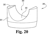
図20は、本発明で使用する挿入物260の別の実施形態の斜視図である。挿入物260は、中に形成された凹形の陥凹部264を備えた上面262を有する、ほぼ円筒形のボディ261を含む。挿入物260は挿入物210の代わりに、またはそれに加えて使用することができる。好ましい実施形態では、挿入物260は、図1、8、10、および12に示すような相互連結ボディの開口またはアイボルト内に配設される。
FIG. 20 is a perspective view of another embodiment of an
図21は、本発明による挿入物268のさらに別の実施形態の斜視図である。挿入物268は、上面272および中に形成された陥凹部274を含む。陥凹部274は上向きに延びる側壁、およびそれらの間にある底または谷263を含む。陥凹部274は、ほぼ長方形または正方形の断面部分を示し、断面が長方形のシャフトを受けるサイズおよび形状になっている。挿入物268は、その中に挿入される雄型連結部材のほぼ正方形または長方形のシャフトを受けそれを支えるように、図20に示す挿入物260と同様にアイボルト内に配設することができる。連結部材のシャフトは陥凹部274の底263に置くことができる。一実施形態では、底263をシャフトと摩擦係合させ、それによってシャフトを相互連結ボディシャフト内に固定することができる。
FIG. 21 is a perspective view of yet another embodiment of an
さらに他の実施形態では、本発明は、連結部材のシャフトおよび/または相互連結要素のスタッドのどちらかに摩擦係合するように設けられた円形のOリングとして形成された挿入物を含むことができる。 In yet another embodiment, the invention includes an insert formed as a circular O-ring provided to frictionally engage either the shaft of the connecting member and / or the stud of the interconnecting element. it can.
挿入物260および268は生体適合性材料から形成することができる。好ましくは、挿入物260および268は、開口内で雄型シャフトに限定的な動きをさせるような材料から形成される。これらの材料の例には、金属材料、セラミック、複合物、および好ましくはエラストマー材料がある。
ここで図22を参照すると、特に挿入物260および274などの摩擦的挿入物とともに使用するための雌型相互連結部材275が示されている。相互連結部材275は、近位端277に担持された相互連結ボディ276を含む。開口279が相互連結ボディ276を貫いて延びる。開口279は、雄型連結部材12、94、176、196、または302などの雄型連結部材を受け入れるサイズである。さらに、相互連結ボディ276は、開口279内に窪み278を含む。挿入物260は、陥凹部264を開口279と位置合わせして、窪み278内に配設される。挿入物260は、雄型連結部材のシャフトを受け入れることができ、または中に受け入れたシャフトを部分的に取り囲むことができる。したがって、開口279(および陥凹部264)内でのシャフトの動きは、締結具307を固締することによって生じる力の大きさに応じて制限される。構成要素、すなわち雄型連結部材、雌型連結部材、挿入物、および締結具を、製造業者があらかじめ組み立てて外科医に提供することができる。あらかじめ組立て済みの構成要素によって連結の限定的な動きが可能になり、その結果、術中の相互連結組立体の埋め込みが容易になる。
Referring now to FIG. 22, there is shown a
図23は、本発明による相互連結組立体330のさらに別の実施形態の部分分解図である。相互連結組立体330は、相互連結要素332、雄型連結部材334、雌型連結部材336(ボディ346を断面図で示す)、および締結具338を含む。相互連結要素332は、中を貫く開口340を有するほぼ円筒形のボディとして設けられる。好ましい実施形態では、開口340は非円形、より好ましくは楕円形の断面を有するものとして設けられる。開口340は、雄型連結部材334の一部を摺動可能に受け入れるように設けられる。相互連結要素332は、第1端342および反対側の第2端341を含む。第1端342は、雌型連結部材336の一部の内部に係合するように適合された周縁部または稜部344を含む。稜部344と雌型連結部材336を組み合わせることによって、雌型連結部材336を相互連結要素332に最初に固定するためのクリックロック係合が、それぞれの構成要素を相対的に動けるようにしながら、もたらされる。
FIG. 23 is a partially exploded view of yet another embodiment of an
さらに図24を参照すると、図は雌型連結部材336の断面図を示し、ボディ346の内部に稜部344と係合し接触するための溝348を含むことが認められる。ボディ346に相互連結要素332の頂部が最初に挿入されると、稜部344は溝348内に係合する。好ましい実施形態では、稜部344は、ボディ346内への挿入を容易にするために、第1端343から第2端345へと延びるスロープまたは傾斜のある表面を備える。さらに、稜部344は、雌型連結部材336が相互連結要素332から後退するのを防ぐために、溝348の内部を支えそれに接触するロック部または段350を含む。これにより、2つの構成要素間に最初のロック連結がもたらされる。ただし、このように係合されているものの、雄型連結部材334、雌型連結部材336、および相互連結要素332のそれぞれは、どの構成部品も外す必要なしに自由に調整可能である。
Still referring to FIG. 24, the figure shows a cross-sectional view of the
さらに図24を参照すると、相互連結要素332の断面図が示されている。好ましい実施形態では、雄型連結部材334および雌型連結部材336は、ボディ346のねじ付き内面で締結具338のトルクを下に向けることにより、(互いに対して)所望の向きでロックすることができる。締結具338を下向きに固締すると、雌型部分336をボディ346に対して固定するのに役立つ。さらにボディ346の下面352は、図23に示すように、シャフト354の一部に係合する。
Still referring to FIG. 24, a cross-sectional view of the interconnecting
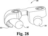
図25から図29は、本発明による連結組立体360の別な実施形態である。連結組立体360は、二重連結器として設けることができる。好ましい実施形態では、二重連結器は、共通ロッドまたはバー361から付随する2つ以上の脊椎ロッド連結部364、366を含む一体型ユニットとして設けられる。例示された実施形態では、連結部364および366は互いにほぼ平行に並んでいる。
25-29 are another embodiment of a
脊椎ロッド連結部材366は、フック部材370の周方向内側に沿って延びるサドルまたはリッジ368を含むように設けられることが認められる。内面362はバー361から先端363へと垂直方向に、かつ第1側面365aから反対側の第2側面365bへと水平方向に、両方向で湾曲している。他の実施形態では、内面362は第1方向に湾曲し、かつ第1方向に対して傾斜した第2方向にも湾曲する。代替実施形態では、内面362は第1方向に対して直角、あるいは第1方向に対して鋭角または鈍角のどちらかである第2方向に湾曲する。さらに湾曲の大きさまたは程度は、所望の通り変化させることができる。
It will be appreciated that the spinal
サドル・リッジ368は、収容された脊椎ロッドを、連結部364内に収容された脊椎ロッドに対して可変角でフック部材370内部に置くことができるようにするために設けられる。代替実施形態では、脊椎ロッド固定部364および366の両方が、リッジ368および表面362と同様のリッジまたはサドルを含むことができる。この実施形態では、(図28および図29に示す)2つの収容された脊椎ロッド367および369の間の角度は、広い範囲で変わり得る。さらに、2つの収容された脊椎ロッドは、異なる平面上にあっても、すなわち2つのロッドが同一平面上になくても、互いに固定することができる。
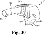
図30は、雄型連結部材371のさらに別の実施形態である。雄型連結部材371は、図1に示す雄型連結部材12のシャフト26および突起28と同様の、相互連結ボディに係合する突起374を有するシャフト372を含むことが認められる。雄型連結部材371は、フック部材380の内側円周部の周りに延びるサドルまたはリッジ378を有する脊椎ロッド固定部376を含む。(リッジ368と同様の)リッジ378は、収容された脊椎ロッドを様々な向きで固定することを可能にする。さらに、本出願で他の雄型連結部材とともに述べたように、ねじ付き開口387をねじ付き締結具(図1、6a、および6b参照)と組み合わせて使用して、細長い部材を支え固定することができる。
FIG. 30 shows still another embodiment of the male connecting member 371. It will be appreciated that the male coupling member 371 includes a
図31は、1対の細長い部材388および390を含む脊柱386の図である。細長い部材388および390は脊椎ロッドとすることができる。さらに、細長い部材は図に示したよりも短くも長くもすることができることを理解されたい。さらに、細長い部材は、脊柱の様々な位置に配置し椎骨の様々な解剖学的構造物に取り付けることができる。
FIG. 31 is an illustration of a spinal column 386 that includes a pair of
細長い部材388および390は、本明細書で述べたようにして設けられる複数の相互連結組立体392、394、および396と相互連結される。相互連結組立体392、394、および396は、10、110、174、194、246、300、310、360、および371を含む本明細書で述べたもののうちのいずれかから選択することができる。いくつかの実施形態では、連結組立体は同じ連結組立体である必要はない。すなわち、連結組立体392は394と同じである必要はなく、396と同じである必要もない。
The
本明細書で述べた脊椎固定システムの様々な構成部品は、既知の方法によって、好ましくはステンレス・スチール、チタン、および他の適切な材料を含む生体適合材料および/または合金から形成される。 The various components of the spinal fixation system described herein are formed by known methods, preferably from biocompatible materials and / or alloys, including stainless steel, titanium, and other suitable materials.
さらに、特定の構成部品および構造を有する脊椎固定システムの様々な実施形態を本明細書で説明し例示してきたが、どの選択された実施形態も、他の実施形態で述べた1つまたは複数の特定の構成部品および/または構造を可能であれば含むことができ、そうしたものとして本発明の範囲内に含まれるものであることを理解されたい。 Furthermore, although various embodiments of spinal fixation systems having particular components and structures have been described and illustrated herein, any selected embodiment may include one or more of the other embodiments described in other embodiments. It is to be understood that certain components and / or structures can be included where possible and as such are within the scope of the present invention.
特定の方向への言及、例えば、上向き、上方、下向き、下方、垂直、または平行などは図示のため、または様々な構成部品を互いに識別または区別しやすくするためのものにすぎないことを理解されたい。これらの言及は、本明細書で述べた脊椎固定のためのシステムおよび/または方法をどのようにも限定するものとして解釈すべきではない。 It is understood that references to specific directions, such as upward, upward, downward, downward, vertical, or parallel, are merely for illustration purposes or to facilitate identification or differentiation of various components from one another. I want. These references should not be construed as limiting in any way the systems and / or methods for spinal fixation described herein.
本発明は、当業者なら思いつくような修正を企図している。本発明において実施された構成部品およびシステムは、本発明の精神から逸脱することなく当業者なら思いつくように、改変し、再構成し、置き換え、削除し、複製し、組み合わせ、あるいは他の工程に追加できることも企図されている。さらに、これらの工程に含まれる様々な段階、ステップ、手順、技法、段階、および操作は、当業者なら思いつくように改変し、再構成し、置き換え、削除し、複製し、あるいは組み合わせることができることも企図されている。本明細書に引用したすべての出版物、特許、および特許出願を、あたかも個々の出版物、特許、および特許出願がそれぞれ参照によって援用されその全体が本明細書に記載されていることが具体的かつ個別的に示されているかのように、参照によって援用するものとする。 The present invention contemplates modifications that would occur to those skilled in the art. The components and systems implemented in the present invention may be modified, reconfigured, replaced, deleted, duplicated, combined, or otherwise processed, as would occur to those skilled in the art without departing from the spirit of the present invention. It is also contemplated that it can be added. In addition, the various steps, steps, procedures, techniques, steps, and operations included in these processes can be modified, reconfigured, replaced, deleted, duplicated, or combined as would occur to those skilled in the art. Is also contemplated. All publications, patents, and patent applications cited herein are specifically incorporated by reference, with each individual publication, patent, and patent application incorporated herein by reference in their entirety. And are incorporated by reference as if individually indicated.
さらに、本明細書で述べたどのような動作理論、立証、または知見も本発明の理解をさらに深めるためのものであり、本発明の範囲はそのような理論、立証、または知見に従属するものではない。 In addition, any theory of operation, proof, or knowledge discussed herein is for further understanding of the invention, and the scope of the invention is dependent on such theory, proof, or knowledge. is not.
以上、本発明を図面および上述の説明によって詳細に例示し説明したが、それらは例示のためのものであり限定的な性質のものではないと考えられ、好ましい実施形態を示し説明したものにすぎず、本発明の精神の範囲に含まれる変更および修正が保護されることが望まれることを理解されたい。 While the invention has been illustrated and described in detail in the drawings and foregoing description, they are intended to be illustrative and not restrictive in nature and merely illustrate preferred embodiments. Rather, it should be understood that changes and modifications within the spirit of the invention are desired to be protected.
Claims (11)
シャフトと、
前記第1の部材を少なくとも部分的に取り囲む形状の湾曲部を有する第1内面を含む第1フックと、
前記第1フックから軸方向にずれた位置で前記シャフトに連結された第1端を含む第2フックと
を含み、
前記第2フックが、前記シャフトから横方向に間隔を置いた第2端で終端し、
前記第2フックが、前記第2の部材を少なくとも部分的に取り囲む形状の湾曲部を有する第2内面を含み、
前記第2フックの前記湾曲部が、互いに異なる2方向に湾曲した内面を有し、
前記第2フックの前記湾曲部が、当該湾曲部に沿って前記第1端から前記第2端の方向に延びるリッジを含む、装置。An interconnection device for securing a pair of elongated first and second members that are not parallel to each other ,
A shaft,
A first hook including a first inner surface having a curved portion shaped to at least partially surround the first member;
A second hook including a first end coupled to the shaft at a position axially offset from the first hook;
The second hook terminates at a second end laterally spaced from the shaft;
The second hook is seen containing a second inner surface having a curved portion having a shape surrounding the second member at least partially,
The curved portion of the second hook has an inner surface curved in two different directions;
The apparatus, wherein the curved portion of the second hook includes a ridge extending along the curved portion from the first end toward the second end .
前記開口内でねじ込み式に受け入れられるねじ付き締結具とを含み、
前記開口および前記締結具が前記第2フック内で細長い部材を固定するように配置される、請求項1に記載の装置。A threaded opening through the shaft;
A threaded fastener that is threadably received within the opening;
The apparatus of claim 1, wherein the opening and the fastener are arranged to secure an elongated member within the second hook.
Applications Claiming Priority (3)
| Application Number | Priority Date | Filing Date | Title |
|---|---|---|---|
| US42170102P | 2002-10-28 | 2002-10-28 | |
| US10/695,068 US8066743B2 (en) | 2002-10-28 | 2003-10-28 | Multi-axial, cross-link connector system for spinal implants |
| PCT/US2003/034128 WO2004039268A1 (en) | 2002-10-28 | 2003-10-28 | Multi-axial, cross-link connector system for spinal implants |
Publications (2)
| Publication Number | Publication Date |
|---|---|
| JP2006503672A JP2006503672A (en) | 2006-02-02 |
| JP4383349B2 true JP4383349B2 (en) | 2009-12-16 |
Family
ID=37768744
Family Applications (2)
| Application Number | Title | Priority Date | Filing Date |
|---|---|---|---|
| JP2004548517A Expired - Fee Related JP4383349B2 (en) | 2002-10-28 | 2003-10-28 | Multi-axis cross-connect system for spinal implants |
| JP2004548519A Expired - Fee Related JP4414889B2 (en) | 2002-10-28 | 2003-10-28 | Cross connector assembly for interconnecting a pair of orthopedic rods |
Family Applications After (1)
| Application Number | Title | Priority Date | Filing Date |
|---|---|---|---|
| JP2004548519A Expired - Fee Related JP4414889B2 (en) | 2002-10-28 | 2003-10-28 | Cross connector assembly for interconnecting a pair of orthopedic rods |
Country Status (6)
| Country | Link |
|---|---|
| US (1) | US8066743B2 (en) |
| EP (2) | EP1567074B1 (en) |
| JP (2) | JP4383349B2 (en) |
| AU (1) | AU2003285028B2 (en) |
| CA (2) | CA2502861A1 (en) |
| WO (3) | WO2004039268A1 (en) |
Families Citing this family (84)
| Publication number | Priority date | Publication date | Assignee | Title |
|---|---|---|---|---|
| US20030114853A1 (en) * | 2001-10-12 | 2003-06-19 | Ian Burgess | Polyaxial cross connector |
| US7066938B2 (en) * | 2002-09-09 | 2006-06-27 | Depuy Spine, Inc. | Snap-on spinal rod connector |
| US8029543B2 (en) | 2002-10-28 | 2011-10-04 | Warsaw Othopedic, Inc. | Multi-axial, cross-link connector system for spinal implants |
| US7918876B2 (en) | 2003-03-24 | 2011-04-05 | Theken Spine, Llc | Spinal implant adjustment device |
| US7771474B2 (en) * | 2003-07-01 | 2010-08-10 | Seaspine, Inc. | Transverse connector system |
| JP2007502677A (en) | 2003-08-20 | 2007-02-15 | ウォーソー・オーソペディック・インコーポレーテッド | Multi-axis orthopedic devices and systems, eg for spinal surgery |
| US7744633B2 (en) | 2003-10-22 | 2010-06-29 | Pioneer Surgical Technology, Inc. | Crosslink for securing spinal rods |
| US8480712B1 (en) | 2004-01-06 | 2013-07-09 | Nuvasive, Inc. | System and method for performing spinal fixation |
| US7104993B2 (en) * | 2004-02-10 | 2006-09-12 | Atlas Spine, Inc. | Cross link system |
| US7909852B2 (en) * | 2004-03-31 | 2011-03-22 | Depuy Spine Sarl | Adjustable-angle spinal fixation element |
| US8236028B2 (en) | 2004-03-31 | 2012-08-07 | Depuy Spine Sarl | Spinal rod connector |
| US7717939B2 (en) | 2004-03-31 | 2010-05-18 | Depuy Spine, Inc. | Rod attachment for head to head cross connector |
| US7645294B2 (en) | 2004-03-31 | 2010-01-12 | Depuy Spine, Inc. | Head-to-head connector spinal fixation system |
| US20050228377A1 (en) * | 2004-04-07 | 2005-10-13 | Depuy Spine, Inc. | Spinal cross-connectors |
| US8034082B2 (en) * | 2004-07-08 | 2011-10-11 | Globus Medical, Inc. | Transverse fixation device for spinal fixation systems |
| US8114158B2 (en) | 2004-08-03 | 2012-02-14 | Kspine, Inc. | Facet device and method |
| US7717938B2 (en) | 2004-08-27 | 2010-05-18 | Depuy Spine, Inc. | Dual rod cross connectors and inserter tools |
| US7959653B2 (en) * | 2004-09-03 | 2011-06-14 | Lanx, Inc. | Spinal rod cross connector |
| US20070225713A1 (en) * | 2004-10-20 | 2007-09-27 | Moti Altarac | Systems and methods for posterior dynamic stabilization of the spine |
| US7491238B2 (en) * | 2004-12-23 | 2009-02-17 | Impliant Ltd. | Adjustable spinal prosthesis |
| US20060241598A1 (en) * | 2005-03-07 | 2006-10-26 | Khalili Farid B | Center locking cross-connector with eccentric cam rod engagement |
| US20060271045A1 (en) * | 2005-05-27 | 2006-11-30 | Depuy Spine, Inc. | Spinal cross-connector |
| US7879074B2 (en) * | 2005-09-27 | 2011-02-01 | Depuy Spine, Inc. | Posterior dynamic stabilization systems and methods |
| JP2007167621A (en) * | 2005-11-24 | 2007-07-05 | Olympus Biomaterial Corp | Spinous process spacer |
| US20070173829A1 (en) * | 2006-01-23 | 2007-07-26 | Sdgi Holdings, Inc. | Devices and methods for connecting vertebral rods |
| US7837714B2 (en) * | 2006-04-10 | 2010-11-23 | Warsaw Orthopedic, Inc. | Methods and devices for the interconnection of bone attachment devices |
| US7722648B2 (en) * | 2006-04-10 | 2010-05-25 | Warsaw Orthopedic, Inc. | Crosslink interconnection of bone attachment devices |
| US20070288009A1 (en) * | 2006-06-08 | 2007-12-13 | Steven Brown | Dynamic spinal stabilization device |
| US20080021455A1 (en) * | 2006-07-21 | 2008-01-24 | Depuy Spine, Inc. | Articulating Sacral or Iliac Connector |
| US20080021456A1 (en) * | 2006-07-21 | 2008-01-24 | Depuy Spine, Inc. | Sacral or iliac cross connector |
| US7922746B2 (en) | 2006-08-31 | 2011-04-12 | Warsaw Orthopedic, Inc. | Spinal rod extenders and methods of use |
| AU2007289258A1 (en) * | 2006-08-31 | 2008-03-06 | Warsaw Orthopedic, Inc. | Spinal rod extenders and methods of use |
| US8361117B2 (en) | 2006-11-08 | 2013-01-29 | Depuy Spine, Inc. | Spinal cross connectors |
| US7744632B2 (en) | 2006-12-20 | 2010-06-29 | Aesculap Implant Systems, Inc. | Rod to rod connector |
| US9962194B2 (en) * | 2007-01-15 | 2018-05-08 | Innovative Delta Technology, Llc | Polyaxial spinal stabilizer connector and methods of use thereof |
| EP2301456B1 (en) * | 2007-02-23 | 2013-04-17 | Biedermann Technologies GmbH & Co. KG | Rod connector for stabilizing vertebrae |
| WO2009076107A1 (en) | 2007-12-13 | 2009-06-18 | Trinity Orthopedics, Llc | Spinal transverse connector |
| FR2927791B1 (en) * | 2008-02-26 | 2011-02-18 | Clariance | ARTICULAR PROSTHESIS POSTERIEURE LUMBAR WITH ROTULE |
| US9060813B1 (en) | 2008-02-29 | 2015-06-23 | Nuvasive, Inc. | Surgical fixation system and related methods |
| US8828058B2 (en) | 2008-11-11 | 2014-09-09 | Kspine, Inc. | Growth directed vertebral fixation system with distractible connector(s) and apical control |
| US8998961B1 (en) | 2009-02-26 | 2015-04-07 | Lanx, Inc. | Spinal rod connector and methods |
| US8357183B2 (en) | 2009-03-26 | 2013-01-22 | Kspine, Inc. | Semi-constrained anchoring system |
| KR101000892B1 (en) * | 2009-05-04 | 2010-12-13 | (주)엘앤케이바이오메드 | Spinal Side-Click Rod Connecting Device |
| US8372120B2 (en) | 2009-05-20 | 2013-02-12 | Spine Wave, Inc. | Multi-axial cross connector |
| US8652176B2 (en) * | 2009-05-29 | 2014-02-18 | Custom Spine, Inc. | Polyaxial screw connection assembly |
| US9168071B2 (en) | 2009-09-15 | 2015-10-27 | K2M, Inc. | Growth modulation system |
| US9814493B2 (en) * | 2009-10-12 | 2017-11-14 | Globus Medical, Inc. | Trans-iliac connector |
| US20110106161A1 (en) * | 2009-10-30 | 2011-05-05 | Warsaw Orthopedic, Inc. | Position Retaining Crosslink |
| US8221466B2 (en) * | 2009-12-23 | 2012-07-17 | Spinecraft, LLC | Transconnector for coupling first and second spinal fixation elements |
| FR2958532B1 (en) * | 2010-04-08 | 2012-12-28 | Implanet | SYSTEM AND DEVICE FOR TRANSVERSE CONNECTION FOR VERTEBRAL COLUMN |
| US9198696B1 (en) | 2010-05-27 | 2015-12-01 | Nuvasive, Inc. | Cross-connector and related methods |
| US8636774B2 (en) * | 2010-12-17 | 2014-01-28 | Spinal Usa, Inc. | Spinal implant apparatuses and methods of implanting and using same |
| US9247964B1 (en) | 2011-03-01 | 2016-02-02 | Nuasive, Inc. | Spinal Cross-connector |
| US9387013B1 (en) | 2011-03-01 | 2016-07-12 | Nuvasive, Inc. | Posterior cervical fixation system |
| US9333009B2 (en) | 2011-06-03 | 2016-05-10 | K2M, Inc. | Spinal correction system actuators |
| US8758411B1 (en) | 2011-10-25 | 2014-06-24 | Nuvasive, Inc. | Implants and methods for treating spinal disorders |
| US8920472B2 (en) | 2011-11-16 | 2014-12-30 | Kspine, Inc. | Spinal correction and secondary stabilization |
| US9451987B2 (en) | 2011-11-16 | 2016-09-27 | K2M, Inc. | System and method for spinal correction |
| US9468469B2 (en) | 2011-11-16 | 2016-10-18 | K2M, Inc. | Transverse coupler adjuster spinal correction systems and methods |
| WO2014172632A2 (en) | 2011-11-16 | 2014-10-23 | Kspine, Inc. | Spinal correction and secondary stabilization |
| US9468468B2 (en) | 2011-11-16 | 2016-10-18 | K2M, Inc. | Transverse connector for spinal stabilization system |
| US8740950B2 (en) * | 2011-12-08 | 2014-06-03 | Spine Wave, Inc. | Methods for percutaneously attaching a cross connector to contralateral spinal constructs |
| US9125691B2 (en) | 2011-12-23 | 2015-09-08 | Amendia, Inc. | Transverse crosslink device |
| US8828056B2 (en) | 2012-04-16 | 2014-09-09 | Aesculap Implant Systems, Llc | Rod to rod cross connector |
| US8771319B2 (en) | 2012-04-16 | 2014-07-08 | Aesculap Implant Systems, Llc | Rod to rod cross connector |
| WO2013170262A2 (en) * | 2012-05-11 | 2013-11-14 | Orthopediatrics Corp. | Surgical connectors and instrumentation |
| US8992575B1 (en) | 2012-06-22 | 2015-03-31 | Seaspine, Inc. | Spinal implants having offsets and hooks |
| US9339309B1 (en) | 2012-10-11 | 2016-05-17 | Nuvasive, Inc. | Systems and methods for inserting cross-connectors |
| US9023087B2 (en) * | 2012-11-09 | 2015-05-05 | Blackstone Medical, Inc. | Percutaneous modular head-to-head cross connector |
| WO2015023420A2 (en) * | 2013-07-25 | 2015-02-19 | Latitude Holdings, Llc | Percutaneous pedicle screw revision system |
| US9468471B2 (en) | 2013-09-17 | 2016-10-18 | K2M, Inc. | Transverse coupler adjuster spinal correction systems and methods |
| US20150230828A1 (en) * | 2014-02-20 | 2015-08-20 | K2M, Inc. | Spinal fixation device |
| KR101622966B1 (en) * | 2014-03-12 | 2016-05-20 | 주식회사 디오메디칼 | Multiaxial connecting rod assembly of spinal fixation device |
| US9737340B1 (en) | 2014-09-16 | 2017-08-22 | Nuvasive, Inc. | Adjustable iliac connector |
| US9763705B2 (en) * | 2014-10-03 | 2017-09-19 | Globus Medical, Inc. | Orthopedic stabilization devices and methods for installation thereof |
| JP2016119035A (en) * | 2014-12-19 | 2016-06-30 | 高松 利光 | Parking position display pole device |
| US9603634B1 (en) | 2015-11-13 | 2017-03-28 | Amendia, Inc. | Percutaneous rod-to-rod cross connector |
| US10905473B2 (en) | 2016-02-15 | 2021-02-02 | Asro Medical | Transverse, and surgical instrument |
| US10575876B2 (en) | 2016-04-20 | 2020-03-03 | K2M, Inc. | Spinal stabilization assemblies with bone hooks |
| US10413331B2 (en) | 2016-12-21 | 2019-09-17 | Spine Wave, Inc. | Spinal stabilization system with head to head cross connector |
| US10893894B2 (en) | 2019-04-24 | 2021-01-19 | Aesculap Implant Systems, Llc | Transverse coupling for surgical implant extensions |
| US11116550B2 (en) * | 2019-04-26 | 2021-09-14 | Warsaw Orthopedic, Inc. | Spinal implant system and method |
| JP2021083546A (en) * | 2019-11-26 | 2021-06-03 | 帝人ナカシマメディカル株式会社 | Spinal fusion connector and spinal fusion implant |
| US11331125B1 (en) * | 2021-10-07 | 2022-05-17 | Ortho Inventions, Llc | Low profile rod-to-rod coupler |
Family Cites Families (44)
| Publication number | Priority date | Publication date | Assignee | Title |
|---|---|---|---|---|
| US3399433A (en) * | 1967-03-13 | 1968-09-03 | Trisal Clips Pty Ltd | Cable clip |
| US4085744A (en) * | 1977-01-31 | 1978-04-25 | David Warren Lewis | Spinal column prostheses orthoses |
| US4274401A (en) * | 1978-12-08 | 1981-06-23 | Miskew Don B W | Apparatus for correcting spinal deformities and method for using |
| PL131829B1 (en) * | 1982-01-18 | 1985-01-31 | Wyzsza Szkola Inzynierska Gagari | Surgical strut for treating spine anomalies |
| US4611582A (en) * | 1983-12-27 | 1986-09-16 | Wisconsin Alumni Research Foundation | Vertebral clamp |
| FR2633177B1 (en) * | 1988-06-24 | 1991-03-08 | Fabrication Materiel Orthopedi | IMPLANT FOR A SPINAL OSTEOSYNTHESIS DEVICE, ESPECIALLY IN TRAUMATOLOGY |
| GB2254394B (en) * | 1988-12-21 | 1993-03-17 | Bristol Myers Squibb Co | Coupler assembly |
| US5024213A (en) * | 1989-02-08 | 1991-06-18 | Acromed Corporation | Connector for a corrective device |
| FR2651992B1 (en) * | 1989-09-18 | 1991-12-13 | Sofamor | IMPLANT FOR ANTERIOR DORSO-LUMBAR SPINE OSTEOSYNTHESIS FOR CORRECTION OF CYPHOSIS. |
| FR2658413B1 (en) * | 1990-02-19 | 1997-01-03 | Sofamor | OSTEOSYNTHESIS DEVICE FOR THE CORRECTION OF SPINAL DEVIATIONS. |
| FR2659225B1 (en) * | 1990-03-08 | 1995-09-08 | Sofamor | TRANSVERSE FIXING DEVICE FOR PROVIDING A RIGID CROSS-LINK BETWEEN TWO RODS OF A SPINAL OSTEOSYNTHESIS SYSTEM. |
| FR2676354B1 (en) * | 1991-05-17 | 1997-11-07 | Vignaud Jean Louis | LOCKABLE CONNECTION DEVICE OF SPINAL OSTEOSYNTHESIS ANCHORING ELEMENTS. |
| FR2681776A1 (en) * | 1991-09-30 | 1993-04-02 | Fixano Sa | VERTEBRAL OSTEOSYNTHESIS DEVICE. |
| DE4231443C1 (en) * | 1992-09-19 | 1993-10-14 | Pennig Dietmar | Osteosynthesis tools |
| US5275600A (en) * | 1992-10-05 | 1994-01-04 | Zimmer, Inc. | Telescoping rod to rod coupler for a spinal system |
| US5549607A (en) * | 1993-02-19 | 1996-08-27 | Alphatec Manufacturing, Inc, | Apparatus for spinal fixation system |
| FR2709411B1 (en) * | 1993-09-03 | 1995-11-17 | Sofamor | Stabilizing forceps of a cervical spinal segment. |
| US5439463A (en) * | 1993-11-12 | 1995-08-08 | Lin; Chih-I | Spinal clamping device |
| US5601552A (en) * | 1994-03-18 | 1997-02-11 | Sofamor, S.N.C. | Fixing device for a rigid transverse connection device between rods of a spinal osteosynthesis system |
| DE69527608T2 (en) | 1994-08-29 | 2003-02-13 | Sofamor | SCREW VALVE FOR FASTENING AN OSTEOSYNTHETIC DEVICE |
| US5716355A (en) * | 1995-04-10 | 1998-02-10 | Sofamor Danek Group, Inc. | Transverse connection for spinal rods |
| US5947966A (en) * | 1995-06-06 | 1999-09-07 | Sdgi Holdings, Inc. | Device for linking adjacent rods in spinal instrumentation |
| JP2000501624A (en) * | 1995-06-06 | 2000-02-15 | エスディージーアイ・ホールディングス・インコーポレーテッド | Apparatus for linking adjacent rods in spinal instrumentation |
| US6193719B1 (en) | 1995-08-24 | 2001-02-27 | Sofamor S.N.C. | Threaded clamping plug for interconnecting two implants of a spinal osteosynthesis instrumentation or other implants |
| US5688273A (en) * | 1995-10-23 | 1997-11-18 | Fastenetix, Llc. | Spinal implant apparatus having a single central rod and plow hooks |
| US5752955A (en) * | 1995-10-30 | 1998-05-19 | Fastenetix, L.L.C. | Sliding shaft variable length cross-link device for use with dual rod apparatus |
| US5709684A (en) * | 1995-12-04 | 1998-01-20 | Fastenetix, Llc | Advanced compression locking variable length cross-link device |
| US5667507A (en) * | 1995-12-04 | 1997-09-16 | Fastenetix, Llc | Compression locking variable length cross-link device for use with dual rod apparatus |
| FR2742040B1 (en) * | 1995-12-07 | 1998-01-23 | Groupe Lepine | ASSEMBLY DEVICE FOR EXTENDED PARTS OF OSTEOSYNTHESIS MATERIAL, ESPECIALLY SPINAL |
| US5669910A (en) * | 1996-01-02 | 1997-09-23 | Pioneer Laboratories, Inc. | Crosslink for implantable rods |
| US5885284A (en) * | 1996-07-11 | 1999-03-23 | Third Millennium Engineering, L.L.C. | Hinged variable length cross-link device |
| US5707372A (en) * | 1996-07-11 | 1998-01-13 | Third Millennium Engineering, Llc. | Multiple node variable length cross-link device |
| FR2767263B1 (en) * | 1997-08-13 | 1999-10-01 | Aesculap Jbs | CLAMPS FOR VERTEBRAL OSTEOSYNTHESIS SYSTEM |
| US6749361B2 (en) * | 1997-10-06 | 2004-06-15 | Werner Hermann | Shackle element for clamping a fixation rod, a method for making a shackle element, a hook with a shackle element and a rode connector with a shackle element |
| US5980523A (en) * | 1998-01-08 | 1999-11-09 | Jackson; Roger | Transverse connectors for spinal rods |
| US6264658B1 (en) * | 1998-07-06 | 2001-07-24 | Solco Surgical Instruments Co., Ltd. | Spine fixing apparatus |
| US6283967B1 (en) * | 1999-12-17 | 2001-09-04 | Synthes (U.S.A.) | Transconnector for coupling spinal rods |
| US6238396B1 (en) * | 1999-10-07 | 2001-05-29 | Blackstone Medical, Inc. | Surgical cross-connecting apparatus and related methods |
| US6217578B1 (en) * | 1999-10-19 | 2001-04-17 | Stryker Spine S.A. | Spinal cross connector |
| US6616668B2 (en) * | 2000-06-09 | 2003-09-09 | Cross Medical Products, Inc. | Adjustable transverse connector for use with a spinal implant system |
| US7485132B1 (en) * | 2000-10-06 | 2009-02-03 | Abbott Spine Inc. | Transverse connector with cam activated engagers |
| US6554832B2 (en) * | 2001-04-02 | 2003-04-29 | Endius Incorporated | Polyaxial transverse connector |
| US6699248B2 (en) * | 2002-05-09 | 2004-03-02 | Roger P. Jackson | Multiple diameter tangential set screw |
| US8029543B2 (en) * | 2002-10-28 | 2011-10-04 | Warsaw Othopedic, Inc. | Multi-axial, cross-link connector system for spinal implants |
-
2003
- 2003-10-28 WO PCT/US2003/034128 patent/WO2004039268A1/en active Application Filing
- 2003-10-28 US US10/695,068 patent/US8066743B2/en active Active
- 2003-10-28 EP EP03779350A patent/EP1567074B1/en not_active Expired - Lifetime
- 2003-10-28 JP JP2004548517A patent/JP4383349B2/en not_active Expired - Fee Related
- 2003-10-28 WO PCT/US2003/034133 patent/WO2004039269A2/en active Application Filing
- 2003-10-28 EP EP03779345A patent/EP1572015B1/en not_active Expired - Lifetime
- 2003-10-28 JP JP2004548519A patent/JP4414889B2/en not_active Expired - Fee Related
- 2003-10-28 AU AU2003285028A patent/AU2003285028B2/en not_active Ceased
- 2003-10-28 CA CA002502861A patent/CA2502861A1/en not_active Abandoned
- 2003-10-28 CA CA002503116A patent/CA2503116A1/en not_active Abandoned
-
2004
- 2004-10-27 WO PCT/US2004/035702 patent/WO2005041794A1/en active Application Filing
Also Published As
| Publication number | Publication date |
|---|---|
| JP4414889B2 (en) | 2010-02-10 |
| EP1572015B1 (en) | 2009-11-25 |
| CA2503116A1 (en) | 2004-05-13 |
| WO2005041794A1 (en) | 2005-05-12 |
| WO2004039269A2 (en) | 2004-05-13 |
| JP2006503672A (en) | 2006-02-02 |
| US20040116928A1 (en) | 2004-06-17 |
| CA2502861A1 (en) | 2004-05-13 |
| US8066743B2 (en) | 2011-11-29 |
| WO2004039268A1 (en) | 2004-05-13 |
| AU2003285033A1 (en) | 2004-05-25 |
| EP1567074B1 (en) | 2009-11-18 |
| WO2004039269A3 (en) | 2004-10-07 |
| AU2003285028A1 (en) | 2004-05-25 |
| EP1572015A1 (en) | 2005-09-14 |
| AU2003285028B2 (en) | 2008-02-21 |
| JP2006503673A (en) | 2006-02-02 |
| EP1567074A2 (en) | 2005-08-31 |
Similar Documents
| Publication | Publication Date | Title |
|---|---|---|
| JP4383349B2 (en) | Multi-axis cross-connect system for spinal implants | |
| US10869695B2 (en) | Tandem rod connectors and related methods | |
| US8414617B2 (en) | Multi axial cross link connector system for spinal implants | |
| JP4584876B2 (en) | Fixing assembly | |
| US7819902B2 (en) | Medialised rod pedicle screw assembly | |
| JP5599316B2 (en) | Surgical fixation system and related methods | |
| EP2769692B1 (en) | Iliosacral polyaxial screw | |
| JP4146500B2 (en) | Device for fixing the spine | |
| US9649137B2 (en) | Spinal stabilization system | |
| AU2009279618A1 (en) | Bone screw assembly | |
| JP2004537354A (en) | Spinal stabilization system and method | |
| JP7350765B2 (en) | Multipoint fixation implants and related methods | |
| CN114502089A (en) | Multi-point angled fixation implant for multiple screws | |
| US20120035667A1 (en) | Locking mechanisms for pivoting bone anchors | |
| AU2003285033B2 (en) | Multi-axial, orthopaedic rod cross-link connector system for correcting spinal defects |
Legal Events
| Date | Code | Title | Description |
|---|---|---|---|
| A621 | Written request for application examination |
Free format text: JAPANESE INTERMEDIATE CODE: A621 Effective date: 20060314 |
|
| A711 | Notification of change in applicant |
Free format text: JAPANESE INTERMEDIATE CODE: A712 Effective date: 20061011 |
|
| A131 | Notification of reasons for refusal |
Free format text: JAPANESE INTERMEDIATE CODE: A131 Effective date: 20090402 |
|
| A601 | Written request for extension of time |
Free format text: JAPANESE INTERMEDIATE CODE: A601 Effective date: 20090629 |
|
| A602 | Written permission of extension of time |
Free format text: JAPANESE INTERMEDIATE CODE: A602 Effective date: 20090706 |
|
| A521 | Written amendment |
Free format text: JAPANESE INTERMEDIATE CODE: A523 Effective date: 20090729 |
|
| TRDD | Decision of grant or rejection written | ||
| A01 | Written decision to grant a patent or to grant a registration (utility model) |
Free format text: JAPANESE INTERMEDIATE CODE: A01 Effective date: 20090821 |
|
| A01 | Written decision to grant a patent or to grant a registration (utility model) |
Free format text: JAPANESE INTERMEDIATE CODE: A01 |
|
| A61 | First payment of annual fees (during grant procedure) |
Free format text: JAPANESE INTERMEDIATE CODE: A61 Effective date: 20090918 |
|
| FPAY | Renewal fee payment (event date is renewal date of database) |
Free format text: PAYMENT UNTIL: 20121002 Year of fee payment: 3 |
|
| R150 | Certificate of patent or registration of utility model |
Ref document number: 4383349 Country of ref document: JP Free format text: JAPANESE INTERMEDIATE CODE: R150 Free format text: JAPANESE INTERMEDIATE CODE: R150 |
|
| FPAY | Renewal fee payment (event date is renewal date of database) |
Free format text: PAYMENT UNTIL: 20131002 Year of fee payment: 4 |
|
| R250 | Receipt of annual fees |
Free format text: JAPANESE INTERMEDIATE CODE: R250 |
|
| R250 | Receipt of annual fees |
Free format text: JAPANESE INTERMEDIATE CODE: R250 |
|
| R250 | Receipt of annual fees |
Free format text: JAPANESE INTERMEDIATE CODE: R250 |
|
| R250 | Receipt of annual fees |
Free format text: JAPANESE INTERMEDIATE CODE: R250 |
|
| R250 | Receipt of annual fees |
Free format text: JAPANESE INTERMEDIATE CODE: R250 |
|
| R250 | Receipt of annual fees |
Free format text: JAPANESE INTERMEDIATE CODE: R250 |
|
| R250 | Receipt of annual fees |
Free format text: JAPANESE INTERMEDIATE CODE: R250 |
|
| R250 | Receipt of annual fees |
Free format text: JAPANESE INTERMEDIATE CODE: R250 |
|
| LAPS | Cancellation because of no payment of annual fees |