JP4383190B2 - Attachment structure for cosmetic cover of solar cell module, and solar cell module. - Google Patents
Attachment structure for cosmetic cover of solar cell module, and solar cell module. Download PDFInfo
- Publication number
- JP4383190B2 JP4383190B2 JP2004020826A JP2004020826A JP4383190B2 JP 4383190 B2 JP4383190 B2 JP 4383190B2 JP 2004020826 A JP2004020826 A JP 2004020826A JP 2004020826 A JP2004020826 A JP 2004020826A JP 4383190 B2 JP4383190 B2 JP 4383190B2
- Authority
- JP
- Japan
- Prior art keywords
- solar cell
- cell module
- frame
- piece
- frame body
- Prior art date
- Legal status (The legal status is an assumption and is not a legal conclusion. Google has not performed a legal analysis and makes no representation as to the accuracy of the status listed.)
- Expired - Fee Related
Links
- 239000002537 cosmetic Substances 0.000 title claims description 15
- 230000002093 peripheral effect Effects 0.000 claims description 9
- 238000003780 insertion Methods 0.000 claims description 4
- 230000037431 insertion Effects 0.000 claims description 4
- 238000005034 decoration Methods 0.000 claims 1
- 229910052751 metal Inorganic materials 0.000 description 8
- 239000002184 metal Substances 0.000 description 8
- 229910052782 aluminium Inorganic materials 0.000 description 3
- XAGFODPZIPBFFR-UHFFFAOYSA-N aluminium Chemical compound [Al] XAGFODPZIPBFFR-UHFFFAOYSA-N 0.000 description 3
- 238000005452 bending Methods 0.000 description 3
- 238000012986 modification Methods 0.000 description 2
- 230000004048 modification Effects 0.000 description 2
- 238000000034 method Methods 0.000 description 1
- 239000007779 soft material Substances 0.000 description 1
- 239000005341 toughened glass Substances 0.000 description 1
Images


Classifications
-
- F—MECHANICAL ENGINEERING; LIGHTING; HEATING; WEAPONS; BLASTING
- F24—HEATING; RANGES; VENTILATING
- F24S—SOLAR HEAT COLLECTORS; SOLAR HEAT SYSTEMS
- F24S25/00—Arrangement of stationary mountings or supports for solar heat collector modules
- F24S25/60—Fixation means, e.g. fasteners, specially adapted for supporting solar heat collector modules
-
- F—MECHANICAL ENGINEERING; LIGHTING; HEATING; WEAPONS; BLASTING
- F24—HEATING; RANGES; VENTILATING
- F24S—SOLAR HEAT COLLECTORS; SOLAR HEAT SYSTEMS
- F24S25/00—Arrangement of stationary mountings or supports for solar heat collector modules
- F24S25/20—Peripheral frames for modules
-
- Y—GENERAL TAGGING OF NEW TECHNOLOGICAL DEVELOPMENTS; GENERAL TAGGING OF CROSS-SECTIONAL TECHNOLOGIES SPANNING OVER SEVERAL SECTIONS OF THE IPC; TECHNICAL SUBJECTS COVERED BY FORMER USPC CROSS-REFERENCE ART COLLECTIONS [XRACs] AND DIGESTS
- Y02—TECHNOLOGIES OR APPLICATIONS FOR MITIGATION OR ADAPTATION AGAINST CLIMATE CHANGE
- Y02B—CLIMATE CHANGE MITIGATION TECHNOLOGIES RELATED TO BUILDINGS, e.g. HOUSING, HOUSE APPLIANCES OR RELATED END-USER APPLICATIONS
- Y02B10/00—Integration of renewable energy sources in buildings
- Y02B10/10—Photovoltaic [PV]
-
- Y—GENERAL TAGGING OF NEW TECHNOLOGICAL DEVELOPMENTS; GENERAL TAGGING OF CROSS-SECTIONAL TECHNOLOGIES SPANNING OVER SEVERAL SECTIONS OF THE IPC; TECHNICAL SUBJECTS COVERED BY FORMER USPC CROSS-REFERENCE ART COLLECTIONS [XRACs] AND DIGESTS
- Y02—TECHNOLOGIES OR APPLICATIONS FOR MITIGATION OR ADAPTATION AGAINST CLIMATE CHANGE
- Y02E—REDUCTION OF GREENHOUSE GAS [GHG] EMISSIONS, RELATED TO ENERGY GENERATION, TRANSMISSION OR DISTRIBUTION
- Y02E10/00—Energy generation through renewable energy sources
- Y02E10/40—Solar thermal energy, e.g. solar towers
- Y02E10/47—Mountings or tracking
Landscapes
- Engineering & Computer Science (AREA)
- Physics & Mathematics (AREA)
- Life Sciences & Earth Sciences (AREA)
- Sustainable Development (AREA)
- Sustainable Energy (AREA)
- Thermal Sciences (AREA)
- Chemical & Material Sciences (AREA)
- Combustion & Propulsion (AREA)
- Mechanical Engineering (AREA)
- General Engineering & Computer Science (AREA)
- Roof Covering Using Slabs Or Stiff Sheets (AREA)
- Photovoltaic Devices (AREA)
Description
本発明は、太陽電池モジュールの化粧用カバーの取付け装置に関し、詳述すれば屋根上へ取付けられる太陽電池モジュールの化粧用カバーの取付け装置に関する。 The present invention relates to a mounting device for a cosmetic cover of a solar cell module, and more particularly to a mounting device for a cosmetic cover of a solar cell module to be mounted on a roof.
この化粧用カバーを太陽電池モジュールの枠体(接合部材)に取付ける場合は、太陽電池モジュール本体の少なくとも一部に化粧用カバー(周辺部材)を着脱自在に取付ける方法が提案されているが(例えば、特許文献1参照)、前記枠体に固定される固定金具にビスを介して取付けるのが一般的である。
前記文献に記載されたものと同種のものとして、図8及び図9に示すものがあり、以下説明する。太陽電池モジュール本体20は平板状に縦横に複数配列された太陽電池セル21の周縁部が金属製の枠体22により囲まれて形成されており、太陽電池モジュール本体20の外観上の美感を向上するために、固定金具23を介してこの枠体22に化粧用カバー24を固定している。即ち、固定金具23は前記枠体22の側面22A及び鍔部22Bにビス25により固定される側片23Aと、この側片23Aの上端を外方へ折曲して形成されてビス26により化粧用カバー24が固定される上水平片23Bと、前記側片23Aの下端を外方へ折曲して形成した下水平片23Cと、この上水平片23Cの外端部を下方へ折曲して形成されてビス27により化粧用カバー24が固定される垂直片23Dとから構成される。
As the same type as described in the above-mentioned document, there are those shown in FIGS. 8 and 9, which will be described below. The solar cell module
しかし、前記化粧用カバー24を太陽電池モジュール本体20に固定するための固定金具23は太陽電池モジュール本体20の1種類の形状の枠体22にしか対応できないものであった。
However, the
そこで本発明は、太陽電池モジュール本体側面に化粧用カバーを容易に固定できると共に、固定できる太陽電池モジュール本体の種類を拡大することを目的とする。 Then, this invention aims at expanding the kind of solar cell module main body which can fix a cosmetic cover to the side surface of a solar cell module main body easily, and can be fixed.
上記課題を解決するために、本発明は、太陽電池モジュールの枠体に固定された固定部材に化粧用カバーを取付けてなる太陽電池モジュールの化粧用カバーの取付け構造において、前記固定部材は、前記枠体の側面に固定される側片及び前記枠体の下面を支持すると共に前記枠体の下端の位置に対応するように凹部を形成する支持片を有することを特徴とする。 In order to solve the above problems, the present invention provides a mounting structure of a decorative cover of a solar cell module formed by mounting a decorative cover to the fixing member fixed to the frame of the solar cell module, wherein the fixing member, the front It has a supporting piece which supports the side piece fixed to the side of the frame and the lower surface of the frame, and forms a recess so as to correspond to the position of the lower end of the frame .
また、前記枠体は下端に外方に延びる部分を含む鍔を有し、前記鍔は前記凹部に挿入されることを特徴とする。Further, the frame body has a flange including a portion extending outward at a lower end, and the flange is inserted into the recess.
また、前記固定部材は、前記化粧用カバーを固定するための取付け片を有することを特徴とする。Further, the fixing member has an attachment piece for fixing the decorative cover.
また、前記枠体の側面に前記固定部材の側片をビスにより固定する際に、該ビスの斜め挿入を防止するためのリブを前記枠体の取り付け孔周縁部に形成したことを特徴とする。
また、本発明は、化粧用カバーの取付け装置を備える太陽電池モジュールであって、前記取付け装置は、前記太陽電池モジュールの周縁部を囲む枠体の側面に固定される側片及び前記枠体の下面を支持すると共に前記枠体の下端の位置に対応するように凹部を形成する支持片を有する固定部材を含むことを特徴とする。
さらに、本発明は、枠体に固定された固定部材に化粧用カバーを取付けてなる太陽電池モジュールにおいて、前記固定部材は、前記枠体の側面に固定される側片及び前記枠体の下面を支持すると共に前記枠体の下端の位置に対応するように凹部を形成する支持片を有することを特徴とする太陽電池モジュール。 Further, when the side piece of the fixing member is fixed to the side surface of the frame body with a screw, a rib for preventing the diagonal insertion of the screw is formed in the peripheral portion of the attachment hole of the frame body. .
Moreover, this invention is a solar cell module provided with the attachment apparatus of a cosmetic cover, Comprising: The said attachment apparatus of the side piece fixed to the side surface of the frame body surrounding the peripheral part of the said solar cell module, and the said frame body It includes a fixing member having a support piece that supports the lower surface and forms a recess so as to correspond to the position of the lower end of the frame.
Furthermore, the present invention provides a solar cell module in which a decorative cover is attached to a fixing member fixed to a frame, wherein the fixing member includes a side piece fixed to a side surface of the frame and a lower surface of the frame. A solar cell module comprising a support piece that supports and forms a recess so as to correspond to the position of the lower end of the frame.
本発明によれば、太陽電池モジュール本体側面に化粧用カバーを容易に固定できると共に、固定できる太陽電池モジュール本体の種類を拡大することができる。また、枠体に固定部材を固定すべく、固定部材及び枠体にビスを挿入させた際に、斜めにビスを挿入しても当該ビスの先端部がリブに当接することにより、作業者はビスの回転速度が落ちたことを認識でき、斜め挿入を防止することができる。 ADVANTAGE OF THE INVENTION According to this invention, while being able to fix a cosmetic cover to the solar cell module main body side surface easily, the kind of solar cell module main body which can be fixed can be expanded. Further, when a screw is inserted into the fixing member and the frame body in order to fix the fixing member to the frame body, even if the screw is inserted obliquely, the tip of the screw abuts against the rib, It is possible to recognize that the rotational speed of the screw has dropped, and to prevent oblique insertion.
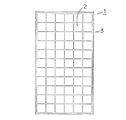
以下、本発明の実施の形態を図に基づき説明する。先ず、図1に示すように、太陽電池モジュール本体1は、平板状に縦横に複数配列された太陽電池パネル2の周縁部(4辺)が枠体3により囲まれて形成されている。即ち、太陽電池パネル2は平面視矩形状であって、その表面には例えば強化ガラス板などが積層されており、この太陽電池パネル2が複数平板状に配列され、その周縁部は一対の長辺側と一対の短辺側の4つの金属製の枠体3に囲まれている。
Hereinafter, embodiments of the present invention will be described with reference to the drawings. First, as shown in FIG. 1, the solar cell module main body 1 is formed by surrounding a peripheral portion (four sides) of a
このように構成された太陽電池モジュール本体1の外観上の美感を向上するために、前記枠体3に外方から複数の空気流通孔4Eを有する化粧用カバー4を固定させる必要があるが、その取付け構造について説明する。図2に示すように、前記太陽電池モジュール本体1の四隅における各角部の近傍位置に各固定金具5を固定する。この固定金具5はアルミニウム製であり、後述するが、前記枠体3の四辺の側面部に数ケ所固定される。
In order to improve the appearance of the solar cell module body 1 configured in this manner, it is necessary to fix the
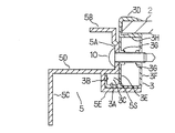
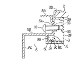
ここで、前記太陽電池モジュール本体1の長辺側(横方向)の前記枠体3にはその下端部に外方に延びた水平板部3Aと、この水平板部3Aの外端部を上方へ折曲した垂直板部3Bとから成る鍔3Cが形成されているが、短辺側(縦方向)の前記枠体3にはこの鍔部3Cは形成されていない。従って、長辺側の前記枠体3の断面形状が表れている図3及び図4と、短辺側の前記枠体3の断面形状が表れている図5と示すように、長辺側の前記枠体3と短辺側の前記枠体3とは断面形状が異なる。
Here, the
即ち、短辺側の前記枠体3は概ね中空角筒状を呈しており、外側面上端部から上方に延びてから内方へ折曲した円筒状のフランジ3Dが形成されており、長辺側の前記枠体3も同様にフランジ3Dが形成されており、更にこの長辺側の前記枠体3には前述したように鍔部3Cが形成されているが、短辺側の前記枠体3にはこの鍔部3Cは形成されていない。なお、この鍔部3Cはアルミニウムで作製されこの鍔部3Cと直交する方向に配設された架台フレーム(図示せず)に固定され、この架台フレームなどを介して屋根の瓦に固定されるものであり、結果として太陽電池モジュール本体1は瓦上に固定されるものである。
That is, the
次に、図2乃至図5に基づいて、前記固定金具5について説明する。この固定金具5は取付孔が所定間隔を存して2個開設されて前記枠体3の側辺3E、3Fに夫々ビス10止めにより前記枠体3に固定される第1取付片5Aと、この第1取付片5Aの上端部を外方に折曲して形成され化粧用カバー4の上片4Aをビス11により固定するための第2取付片5Bと、同じく化粧用カバー4の側片4Bをビス12により固定するための第3取付片5Cと、前記第1取付片5Aと第3取付片5Cとを連結する連結片5Dと、この連結片5Dと共に前記枠体3の鍔3Cが挿入される凹部5Sを形成すると共に該枠体3の下面を支持するための断面L字形状の支持片5Eとから構成される。
Next, the
なお、前記第2取付片5B及び第3取付片5Cには取付孔が形成されていないが、アルミニウム製で軟らかな素材で作製されているため、ビス11、12をネジ込むことにより孔が形成され、ビス11、12を止めることができるものである。
The
そして、前記フランジ3D、側片3E及び上片3Hとで形成される凹部内に太陽電池パネル2が挿入され、この太陽電池パネル2は枠体3で周縁部が囲まれることとなる。
And the
なお、短辺側の前記枠体3はその下面が前記固定金具5の支持片5Eにより支持されるが、長辺側の前記枠体3も同様にその下面が前記固定金具5の支持片5Eにより支持されると共に連結片5Dと支持片5Eとにより形成された凹部5S内に前記鍔3Cが挿入されて支持されることとなる。
The lower surface of the
従って、短辺側の前記枠体3はその下面が前記固定金具5の支持片5Eにより支持されて上下方向が規制されて該短辺側の枠体3への固定金具5の取付時に位置決めが容易となる。また、長辺側の前記枠体3はその下面が前記固定金具5の支持片5Eにより支持されて上下方向が規制されると共に凹部5S内に前記鍔3Cが挿入されて連結片5D及び支持片5Eにより支持されて左右方向及び上下方向が規制されて該長辺側の枠体3への固定金具5の取付時に位置決めが容易となる。
Therefore, the
前記化粧用カバー4は上片4Aと側片4Bとから概ね断面がL字形状を呈するが、前記側片4Bの下端部を内方に折曲してわずかの長さを有する折曲片4Cを形成し、また上片4Aの先端部を下方に折曲してわずかの長さを有する折曲片4Dを形成する。
The
従って、化粧用カバー4を固定金具5に固定する場合には、前記第1取付片5Aを断面がクランク状になるように形成して形成された空間内に前記折曲片4Dを挿入した状態にして各ビス11、12により固定することができる。
Therefore, when the
なお、短辺側及び長辺側の前記枠体3は前述したように、概ね中空角筒状を呈しているが、その垂直な側辺3E、3Fに夫々開設された2個の取付孔の開口縁部には夫々内方に延びた円筒状のリブ3Gが形成されている。従って、図7に示すように、枠体3に固定金具5の第1取付片5Aを固定すべく、固定金具5及び枠体3の取付孔にビス10を嵌合させた際に、斜めにビス10を挿入しても当該ビス10の先端部が前記リブ3Gに当接することにより、作業者はビス10の回転速度が落ちたことを認識でき、斜め挿入を防止することができる。
As described above, the
以上本発明の実施態様について説明したが、上述の説明に基づいて当業者にとって種々の代替例、修正又は変形が可能であり、本発明はその趣旨を逸脱しない範囲で前述の種々の代替例、修正又は変形を包含するものである。 Although the embodiments of the present invention have been described above, various alternatives, modifications, and variations can be made by those skilled in the art based on the above description, and the present invention is not limited to the various alternatives described above without departing from the spirit of the present invention. It includes modifications or variations.
1 太陽電池モジュール本体
2 太陽電池パネル
3 枠体
4 化粧用カバー
5 固定金具
5A 第1取付片
5B 第2取付片
5C 第3取付片
5D 連結片
5E 支持片
5S 凹部
DESCRIPTION OF SYMBOLS 1 Solar cell module
Claims (6)
前記固定部材は、前記枠体の側面に固定される側片及び前記枠体の下面を支持すると共に前記枠体の下端の位置に対応するように凹部を形成する支持片を有することを特徴とする太陽電池モジュールの化粧用カバーの取付け構造。 In the mounting structure of the cosmetic cover of the solar cell module, in which the decorative cover is attached to the fixing member fixed to the frame of the solar cell module,
The fixing member, characterized in that it has a supporting piece which forms a recess so as to correspond to the position of the lower end of the frame to support the lower surface of the pre-Symbol side piece is fixed to the side surface of the frame body and the frame body A mounting structure for a cosmetic cover of a solar cell module.
前記鍔は前記凹部に挿入されることを特徴とする請求項1記載の太陽電池モジュールの化粧用カバーの取付け構造。The said cover is inserted in the said recessed part, The attachment structure of the makeup | decoration cover of the solar cell module of Claim 1 characterized by the above-mentioned.
前記取付け装置は、前記太陽電池モジュールの周縁部を囲む枠体の側面に固定される側片及び前記枠体の下面を支持すると共に前記枠体の下端の位置に対応するように凹部を形成する支持片を有する固定部材を含むことを特徴とする太陽電池モジュール。 A solar cell module provided with a device for attaching a decorative cover,
The attachment device supports the side piece fixed to the side surface of the frame body surrounding the peripheral edge of the solar cell module and the lower surface of the frame body, and forms a recess so as to correspond to the position of the lower end of the frame body. A solar cell module comprising a fixing member having a support piece .
前記固定部材は、前記枠体の側面に固定される側片及び前記枠体の下面を支持すると共に前記枠体の下端の位置に対応するように凹部を形成する支持片を有することを特徴とする太陽電池モジュール。The fixing member includes a side piece fixed to a side surface of the frame body and a support piece that supports a lower surface of the frame body and forms a recess so as to correspond to a position of a lower end of the frame body. Solar cell module.
Priority Applications (1)
| Application Number | Priority Date | Filing Date | Title |
|---|---|---|---|
| JP2004020826A JP4383190B2 (en) | 2004-01-29 | 2004-01-29 | Attachment structure for cosmetic cover of solar cell module, and solar cell module. |
Applications Claiming Priority (1)
| Application Number | Priority Date | Filing Date | Title |
|---|---|---|---|
| JP2004020826A JP4383190B2 (en) | 2004-01-29 | 2004-01-29 | Attachment structure for cosmetic cover of solar cell module, and solar cell module. |
Related Child Applications (1)
| Application Number | Title | Priority Date | Filing Date |
|---|---|---|---|
| JP2009137032A Division JP5052565B2 (en) | 2009-06-08 | 2009-06-08 | Fixing metal fitting for cosmetic cover for solar cell module, and solar cell device provided with solar cell module, cosmetic cover and fixing metal fitting |
Publications (2)
| Publication Number | Publication Date |
|---|---|
| JP2005213835A JP2005213835A (en) | 2005-08-11 |
| JP4383190B2 true JP4383190B2 (en) | 2009-12-16 |
Family
ID=34904644
Family Applications (1)
| Application Number | Title | Priority Date | Filing Date |
|---|---|---|---|
| JP2004020826A Expired - Fee Related JP4383190B2 (en) | 2004-01-29 | 2004-01-29 | Attachment structure for cosmetic cover of solar cell module, and solar cell module. |
Country Status (1)
| Country | Link |
|---|---|
| JP (1) | JP4383190B2 (en) |
Families Citing this family (5)
| Publication number | Priority date | Publication date | Assignee | Title |
|---|---|---|---|---|
| KR101001735B1 (en) | 2008-06-13 | 2010-12-15 | (주)그랜드솔라 | Collecting apparatus for solar heat |
| JP2012007396A (en) * | 2010-06-25 | 2012-01-12 | Noritz Corp | Function panel and function panel mounting member |
| CN201918394U (en) * | 2010-10-28 | 2011-08-03 | 深圳市景佑能源科技有限公司 | Fixing and connecting piece for solar-panel frame |
| JP7141310B2 (en) * | 2018-11-02 | 2022-09-22 | 株式会社カネカ | solar cell unit, building, cover |
| CN112994599B (en) * | 2021-03-05 | 2023-04-28 | 广东中电坤源节能科技有限公司 | Non-full-open type foldable solar device |
-
2004
- 2004-01-29 JP JP2004020826A patent/JP4383190B2/en not_active Expired - Fee Related
Also Published As
| Publication number | Publication date |
|---|---|
| JP2005213835A (en) | 2005-08-11 |
Similar Documents
| Publication | Publication Date | Title |
|---|---|---|
| JP4383190B2 (en) | Attachment structure for cosmetic cover of solar cell module, and solar cell module. | |
| KR20150058986A (en) | A fixing device for a out side panel of building | |
| JP5052565B2 (en) | Fixing metal fitting for cosmetic cover for solar cell module, and solar cell device provided with solar cell module, cosmetic cover and fixing metal fitting | |
| JP2007009418A (en) | Balustrade | |
| JP6184055B2 (en) | Roof structure | |
| KR20090021835A (en) | Frame for soundproof construction, soundproof panel and soundproof wall made of the same | |
| JP6441766B2 (en) | Side frame mounting structure and side frame construction method | |
| JP2006249681A (en) | Wall-mounted outdoor structure | |
| JP4619805B2 (en) | 庇 | |
| JP2007040604A (en) | Outdoor unit of air conditioner | |
| JP7136641B2 (en) | Eaves gutter support and gutter fixing structure | |
| JP2020133273A (en) | Fence mounting structure and fixing metal tool | |
| JP2006077542A (en) | Partition and panel element mounting structure | |
| JP6790191B1 (en) | Panel body | |
| JP6334949B2 (en) | Tile-type support fixture for articles installed on tile roofs | |
| CN219204926U (en) | LED box of pedal type display device and pedal type display device with same | |
| CN2883990Y (en) | Improved ceiling built-in air warmer | |
| KR20110027465A (en) | The ceiling panel | |
| JP2009127223A (en) | Mounting structure of mounting member and easy structure | |
| JP2008280717A (en) | Blind panel fixing structure | |
| KR200410234Y1 (en) | Support structure for a Neon-lamp sign board | |
| JP5226381B2 (en) | Outdoor structure | |
| JP6340260B2 (en) | Functional component mounting structure and bathroom | |
| JP4090399B2 (en) | Trapezoidal window | |
| JP2006169912A (en) | Column frame pedestal and bathroom unit |
Legal Events
| Date | Code | Title | Description |
|---|---|---|---|
| A621 | Written request for application examination |
Free format text: JAPANESE INTERMEDIATE CODE: A621 Effective date: 20061219 |
|
| A977 | Report on retrieval |
Free format text: JAPANESE INTERMEDIATE CODE: A971007 Effective date: 20090312 |
|
| A131 | Notification of reasons for refusal |
Free format text: JAPANESE INTERMEDIATE CODE: A131 Effective date: 20090407 |
|
| A521 | Request for written amendment filed |
Free format text: JAPANESE INTERMEDIATE CODE: A523 Effective date: 20090608 |
|
| TRDD | Decision of grant or rejection written | ||
| A01 | Written decision to grant a patent or to grant a registration (utility model) |
Free format text: JAPANESE INTERMEDIATE CODE: A01 Effective date: 20090825 |
|
| A01 | Written decision to grant a patent or to grant a registration (utility model) |
Free format text: JAPANESE INTERMEDIATE CODE: A01 |
|
| A61 | First payment of annual fees (during grant procedure) |
Free format text: JAPANESE INTERMEDIATE CODE: A61 Effective date: 20090918 |
|
| FPAY | Renewal fee payment (event date is renewal date of database) |
Free format text: PAYMENT UNTIL: 20121002 Year of fee payment: 3 |
|
| R151 | Written notification of patent or utility model registration |
Ref document number: 4383190 Country of ref document: JP Free format text: JAPANESE INTERMEDIATE CODE: R151 |
|
| FPAY | Renewal fee payment (event date is renewal date of database) |
Free format text: PAYMENT UNTIL: 20121002 Year of fee payment: 3 |
|
| FPAY | Renewal fee payment (event date is renewal date of database) |
Free format text: PAYMENT UNTIL: 20131002 Year of fee payment: 4 |
|
| LAPS | Cancellation because of no payment of annual fees |