JP4383053B2 - Micro fluid valve and micro actuator for micro valve - Google Patents
Micro fluid valve and micro actuator for micro valve Download PDFInfo
- Publication number
- JP4383053B2 JP4383053B2 JP2002567724A JP2002567724A JP4383053B2 JP 4383053 B2 JP4383053 B2 JP 4383053B2 JP 2002567724 A JP2002567724 A JP 2002567724A JP 2002567724 A JP2002567724 A JP 2002567724A JP 4383053 B2 JP4383053 B2 JP 4383053B2
- Authority
- JP
- Japan
- Prior art keywords
- permeable membrane
- electrode pad
- valve
- current
- electrode
- Prior art date
- Legal status (The legal status is an assumption and is not a legal conclusion. Google has not performed a legal analysis and makes no representation as to the accuracy of the status listed.)
- Expired - Lifetime
Links
Images


Classifications
-
- F—MECHANICAL ENGINEERING; LIGHTING; HEATING; WEAPONS; BLASTING
- F16—ENGINEERING ELEMENTS AND UNITS; GENERAL MEASURES FOR PRODUCING AND MAINTAINING EFFECTIVE FUNCTIONING OF MACHINES OR INSTALLATIONS; THERMAL INSULATION IN GENERAL
- F16K—VALVES; TAPS; COCKS; ACTUATING-FLOATS; DEVICES FOR VENTING OR AERATING
- F16K99/00—Subject matter not provided for in other groups of this subclass
- F16K99/0001—Microvalves
-
- F—MECHANICAL ENGINEERING; LIGHTING; HEATING; WEAPONS; BLASTING
- F15—FLUID-PRESSURE ACTUATORS; HYDRAULICS OR PNEUMATICS IN GENERAL
- F15C—FLUID-CIRCUIT ELEMENTS PREDOMINANTLY USED FOR COMPUTING OR CONTROL PURPOSES
- F15C5/00—Manufacture of fluid circuit elements; Manufacture of assemblages of such elements integrated circuits
-
- F—MECHANICAL ENGINEERING; LIGHTING; HEATING; WEAPONS; BLASTING
- F16—ENGINEERING ELEMENTS AND UNITS; GENERAL MEASURES FOR PRODUCING AND MAINTAINING EFFECTIVE FUNCTIONING OF MACHINES OR INSTALLATIONS; THERMAL INSULATION IN GENERAL
- F16K—VALVES; TAPS; COCKS; ACTUATING-FLOATS; DEVICES FOR VENTING OR AERATING
- F16K31/00—Actuating devices; Operating means; Releasing devices
- F16K31/02—Actuating devices; Operating means; Releasing devices electric; magnetic
-
- F—MECHANICAL ENGINEERING; LIGHTING; HEATING; WEAPONS; BLASTING
- F16—ENGINEERING ELEMENTS AND UNITS; GENERAL MEASURES FOR PRODUCING AND MAINTAINING EFFECTIVE FUNCTIONING OF MACHINES OR INSTALLATIONS; THERMAL INSULATION IN GENERAL
- F16K—VALVES; TAPS; COCKS; ACTUATING-FLOATS; DEVICES FOR VENTING OR AERATING
- F16K7/00—Diaphragm valves or cut-off apparatus, e.g. with a member deformed, but not moved bodily, to close the passage ; Pinch valves
- F16K7/12—Diaphragm valves or cut-off apparatus, e.g. with a member deformed, but not moved bodily, to close the passage ; Pinch valves with flat, dished, or bowl-shaped diaphragm
- F16K7/123—Diaphragm valves or cut-off apparatus, e.g. with a member deformed, but not moved bodily, to close the passage ; Pinch valves with flat, dished, or bowl-shaped diaphragm the seat being formed on the bottom of the fluid line
-
- F—MECHANICAL ENGINEERING; LIGHTING; HEATING; WEAPONS; BLASTING
- F16—ENGINEERING ELEMENTS AND UNITS; GENERAL MEASURES FOR PRODUCING AND MAINTAINING EFFECTIVE FUNCTIONING OF MACHINES OR INSTALLATIONS; THERMAL INSULATION IN GENERAL
- F16K—VALVES; TAPS; COCKS; ACTUATING-FLOATS; DEVICES FOR VENTING OR AERATING
- F16K7/00—Diaphragm valves or cut-off apparatus, e.g. with a member deformed, but not moved bodily, to close the passage ; Pinch valves
- F16K7/12—Diaphragm valves or cut-off apparatus, e.g. with a member deformed, but not moved bodily, to close the passage ; Pinch valves with flat, dished, or bowl-shaped diaphragm
- F16K7/14—Diaphragm valves or cut-off apparatus, e.g. with a member deformed, but not moved bodily, to close the passage ; Pinch valves with flat, dished, or bowl-shaped diaphragm arranged to be deformed against a flat seat
-
- F—MECHANICAL ENGINEERING; LIGHTING; HEATING; WEAPONS; BLASTING
- F16—ENGINEERING ELEMENTS AND UNITS; GENERAL MEASURES FOR PRODUCING AND MAINTAINING EFFECTIVE FUNCTIONING OF MACHINES OR INSTALLATIONS; THERMAL INSULATION IN GENERAL
- F16K—VALVES; TAPS; COCKS; ACTUATING-FLOATS; DEVICES FOR VENTING OR AERATING
- F16K99/00—Subject matter not provided for in other groups of this subclass
- F16K99/0001—Microvalves
- F16K99/0003—Constructional types of microvalves; Details of the cutting-off member
- F16K99/0015—Diaphragm or membrane valves
-
- F—MECHANICAL ENGINEERING; LIGHTING; HEATING; WEAPONS; BLASTING
- F16—ENGINEERING ELEMENTS AND UNITS; GENERAL MEASURES FOR PRODUCING AND MAINTAINING EFFECTIVE FUNCTIONING OF MACHINES OR INSTALLATIONS; THERMAL INSULATION IN GENERAL
- F16K—VALVES; TAPS; COCKS; ACTUATING-FLOATS; DEVICES FOR VENTING OR AERATING
- F16K99/00—Subject matter not provided for in other groups of this subclass
- F16K99/0001—Microvalves
- F16K99/0034—Operating means specially adapted for microvalves
- F16K99/0042—Electric operating means therefor
- F16K99/0051—Electric operating means therefor using electrostatic means
-
- B—PERFORMING OPERATIONS; TRANSPORTING
- B01—PHYSICAL OR CHEMICAL PROCESSES OR APPARATUS IN GENERAL
- B01L—CHEMICAL OR PHYSICAL LABORATORY APPARATUS FOR GENERAL USE
- B01L3/00—Containers or dishes for laboratory use, e.g. laboratory glassware; Droppers
- B01L3/50—Containers for the purpose of retaining a material to be analysed, e.g. test tubes
- B01L3/502—Containers for the purpose of retaining a material to be analysed, e.g. test tubes with fluid transport, e.g. in multi-compartment structures
- B01L3/5027—Containers for the purpose of retaining a material to be analysed, e.g. test tubes with fluid transport, e.g. in multi-compartment structures by integrated microfluidic structures, i.e. dimensions of channels and chambers are such that surface tension forces are important, e.g. lab-on-a-chip
- B01L3/502738—Containers for the purpose of retaining a material to be analysed, e.g. test tubes with fluid transport, e.g. in multi-compartment structures by integrated microfluidic structures, i.e. dimensions of channels and chambers are such that surface tension forces are important, e.g. lab-on-a-chip characterised by integrated valves
-
- F—MECHANICAL ENGINEERING; LIGHTING; HEATING; WEAPONS; BLASTING
- F16—ENGINEERING ELEMENTS AND UNITS; GENERAL MEASURES FOR PRODUCING AND MAINTAINING EFFECTIVE FUNCTIONING OF MACHINES OR INSTALLATIONS; THERMAL INSULATION IN GENERAL
- F16K—VALVES; TAPS; COCKS; ACTUATING-FLOATS; DEVICES FOR VENTING OR AERATING
- F16K99/00—Subject matter not provided for in other groups of this subclass
- F16K2099/0073—Fabrication methods specifically adapted for microvalves
- F16K2099/0074—Fabrication methods specifically adapted for microvalves using photolithography, e.g. etching
-
- F—MECHANICAL ENGINEERING; LIGHTING; HEATING; WEAPONS; BLASTING
- F16—ENGINEERING ELEMENTS AND UNITS; GENERAL MEASURES FOR PRODUCING AND MAINTAINING EFFECTIVE FUNCTIONING OF MACHINES OR INSTALLATIONS; THERMAL INSULATION IN GENERAL
- F16K—VALVES; TAPS; COCKS; ACTUATING-FLOATS; DEVICES FOR VENTING OR AERATING
- F16K99/00—Subject matter not provided for in other groups of this subclass
- F16K2099/0073—Fabrication methods specifically adapted for microvalves
- F16K2099/008—Multi-layer fabrications
-
- F—MECHANICAL ENGINEERING; LIGHTING; HEATING; WEAPONS; BLASTING
- F16—ENGINEERING ELEMENTS AND UNITS; GENERAL MEASURES FOR PRODUCING AND MAINTAINING EFFECTIVE FUNCTIONING OF MACHINES OR INSTALLATIONS; THERMAL INSULATION IN GENERAL
- F16K—VALVES; TAPS; COCKS; ACTUATING-FLOATS; DEVICES FOR VENTING OR AERATING
- F16K99/00—Subject matter not provided for in other groups of this subclass
- F16K2099/0082—Microvalves adapted for a particular use
- F16K2099/0084—Chemistry or biology, e.g. "lab-on-a-chip" technology
Description
本発明は、超小型装置、および、超小型装置を作動させるアクチュエータ装置について述べられている。さらに詳細には、本発明は、超小型流体装置において使用するためのバルブ構造、および、超小型バルブを作動させるための超小型装置について述べられている。 The present invention describes a micro device and an actuator device for operating the micro device. More particularly, the present invention describes a valve structure for use in a microfluidic device and a microdevice for operating a microvalve.
様々な超小型装置は、その分野において知られており、異なる作業を行う。近年、関心事となる一つの用途は、流体制御装置における分野、特に、超小型バルブである。その超小型バルブは、薬物送達の分野、内燃機関の燃料送出システム、ならびにインクジェットプリンタなどの多くの産業上の用途において有効であることが明らかとなっている。これらの装置は、多くの異なる方法により作られる。 Various micro devices are known in the art and perform different tasks. One application of interest in recent years is in the field of fluid control devices, especially micro valves. The microvalves have proven effective in many industrial applications such as the field of drug delivery, fuel delivery systems for internal combustion engines, and ink jet printers. These devices are made in many different ways.
電子機器および集積回路チップの製造において通常使用されるその多くの技術は、超小型機械装置のマイクロマシニングに適している。これらの超小型装置は、代表的には、マイクロエレクトリカルメカニカルシステム(MEMS)と呼称される。その装置は、非常に小さく、多数の種類の材料で作られ得る。一般的な材料は、集積回路部門で使用されるシリコンウェーハ形のシリコンである。使用され得る他の材料は、ガラスおよびセラミックである。 Many of its techniques commonly used in the manufacture of electronic equipment and integrated circuit chips are suitable for micromachining of micromechanical devices. These microminiature devices are typically referred to as microelectrical mechanical systems (MEMS). The device is very small and can be made of many types of materials. A common material is silicon in the form of silicon wafers used in the integrated circuit sector. Other materials that can be used are glass and ceramic.
超小型バルブの例としては、johnson等に与えられた米国特許第605669号に開示されている。その超小型バルブは、バルブシートを備えるシリコンダイヤフラムおよび流路を含んでいる。そのダイヤフラムは、ダイヤフラムが撓んだ場合、バルブシートに対し閉じるように位置決めされている。別個の作動力が、バルブを開閉するようにそのダイヤフラムに加えられる。その作動装置は、そのダイヤフラムの一方側に力を加えるための圧力がかかっている液体、またはソレノイド機構であってもよい。 An example of a microminiature valve is disclosed in US Pat. No. 6,066,669 to Johnson et al. The microminiature valve includes a silicon diaphragm with a valve seat and a flow path. The diaphragm is positioned to close with respect to the valve seat when the diaphragm is deflected. A separate actuation force is applied to the diaphragm to open and close the valve. The actuator may be a liquid under pressure to apply force to one side of the diaphragm, or a solenoid mechanism.
ガスクロマトグラフィーアッセンブリにおけるバルブのソレノイド作動は、Terry等に与えられた米国特許第4582624号に開示されるように知られている。その作動力は制御することが難しく、また、十分な力をもたらすことが困難なのでこれらの装置は、そのバルブを作動するうえで必ずしも有効ではない。また、そのソレノイド作動式装置は、製造するのに高価であり、装置の一部が効率よく製造されない。 Solenoid actuation of valves in gas chromatography assemblies is known as disclosed in US Pat. No. 4,582,624 issued to Terry et al. These devices are not always effective in operating the valve because the actuation force is difficult to control and it is difficult to provide sufficient force. Also, the solenoid actuated device is expensive to manufacture and some of the device is not efficiently manufactured.
他の超小型アクチュエータ装置は、Trah等に与えられた米国特許第5344117号に開示されている。そのアクチュエータは、シリコン本体の下部に形成される凹部内に湾曲される湾曲要素を有するシリコン本体で作られている。圧力要素は、その湾曲要素の上面に結合され、その湾曲要素の撓みを引き起こす。その圧力要素は、熱膨張および熱収縮で作用するように開示されている。 Another micro actuator device is disclosed in US Pat. No. 5,344,117 to Trah et al. The actuator is made of a silicon body having a bending element that is curved in a recess formed in the lower part of the silicon body. The pressure element is coupled to the upper surface of the bending element and causes the bending element to deflect. The pressure element is disclosed to work with thermal expansion and contraction.
超小型バルブ装置を作動させる他の方法は、柔軟なダイヤフラムを撓ませるために静電力を使用するものである。そのダイヤフラムは、バルブシートを接触させることにより、そのバルブの出口を密封するために使用されている。その静電力は、確実かつ安定した方法で作り出されないことがわかる。この形式の装置の例としては、米国特許第452624号に開示されている。 Another way of operating the microvalve device is to use an electrostatic force to deflect the flexible diaphragm. The diaphragm is used to seal the outlet of the valve by contacting the valve seat. It can be seen that the electrostatic force is not created in a reliable and stable manner. An example of this type of device is disclosed in US Pat. No. 4,526,624.
超小型ポンプは、また、様々用途で知られており、特にインクジェットプリンタを駆動させることで知られている。これらのポンプは、代表的には、その膜を移動させポンピング動作を引き起こすことができる膜に固定された圧電性結晶を有している。この形式の装置の利点は、その膜が温度変化とともに変形できるので温度により変化をもたらされることである。 Microminiature pumps are also known for a variety of applications, particularly for driving ink jet printers. These pumps typically have a piezoelectric crystal fixed to the membrane that can move the membrane and cause a pumping action. The advantage of this type of device is that the membrane is deformable with changes in temperature so that changes are brought about by temperature.
他の形式の超小型装置は、電動アクチュエータにより作動される。一例としては、バイメタル材料で作られた複数の脚部を有する装置である。そのバイメタルの脚部は、加熱され、それぞれ異なる膨張係数により脚部内に応力および反りを引き起こす。その脚部の反りがその装置を作動させる。アクチュエータがオリフィス内の流体流れを増減させるように制御することをもたらすことができるのでこれが、超小型バルブを作動させる典型的な方法である。 Another type of micro device is actuated by an electric actuator. An example is a device having a plurality of legs made of a bimetallic material. The bimetal legs are heated and cause stress and warpage in the legs due to different coefficients of expansion. The warping of the leg activates the device. This is a typical way of operating a microvalve because the actuator can provide control to increase or decrease the fluid flow in the orifice.
他の超小型バルブの構造、および、そのバルブの制御および作動方法は、Gordon等に与えられた米国特許第5058856号、Barthに与えられた米国特許第5780780号、Lisec等に与えられた米国特許第5681024号、Stevenson等に与えられた米国特許第5429713号に開示されている。 Other micro-valve structures and methods for controlling and operating the valves are described in US Pat. No. 5,058,856 to Gordon et al., US Pat. No. 5,780,780 to Barth, US Pat. No. 5,681,024, U.S. Pat. No. 5,429,713 to Stevenson et al.
超小型装置、特に超小型バルブを制御するための先の装置は、多くの目的についてうまくいっている。しかし、他の目的においては不十分な成果しかあがっていない。 Prior devices for controlling micro devices, particularly micro valves, have worked well for many purposes. However, for other purposes it has been insufficient.
従って、様々な超小型装置用の改善された作動装置がその業界において必要とされている。 Therefore, there is a need in the industry for improved actuators for various micro devices.
本発明は、超小型バルブ、および、超小型装置を作動させるためのアクチュエータ装置について述べられている。さらに詳細には、本発明は、超小型バルブのような超小型流体装置、および、超小型装置を作動させるためのアクチュエータについて述べられている。 The present invention describes a micro valve and an actuator device for operating the micro device. More particularly, the present invention describes a microfluidic device, such as a microvalve, and an actuator for operating the microdevice.
従って、本発明の第1の目的は、薬物送達の分野のような様々の医療用途に使用され得る超小型バルブを提供することである。 Accordingly, it is a first object of the present invention to provide a microminiature valve that can be used in various medical applications such as the field of drug delivery.
本発明の他の目的は、マイクロマシン技術により製造され得る超小型バルブを提供することである。 Another object of the present invention is to provide a microminiature valve that can be manufactured by micromachine technology.
本発明のさらなる目的は、マイクロエレクトロメカニカル法により製造され得る超小型アクチュエータを提供することを目的とする。 A further object of the present invention is to provide a micro actuator that can be manufactured by a microelectromechanical method.
本発明の更なる他の目的は、最小限の数の移動部品を有し、製造するのも経済的である超小型バルブを提供することである。 Yet another object of the present invention is to provide a microminiature valve that has a minimal number of moving parts and is economical to manufacture.
本発明の他の目的は、ポリマー材料で作られた膜を有する超小型バルブを提供することであり、そのポリマー材料は、その膜がバルブシートに接触しそのバルブを閉じるように電流をその膜に供給することにより変形される。 Another object of the present invention is to provide a micro-valve having a membrane made of a polymer material, which polymer material conducts current so that the membrane contacts the valve seat and closes the valve. It is deformed by supplying to.
本発明の他の目的は、透過膜を備える電極パッドを有する超小型バルブを提供することであり、その透過膜の厚さは、電流をその電極に供給することにより、膨張可能な厚さである。 Another object of the present invention is to provide a microminiature valve having an electrode pad with a permeable membrane, the thickness of the permeable membrane being such that it can be expanded by supplying current to the electrode. is there.
本発明の他の目的は、バルブシートから離隔され取り付けられる透水膜を備える超小型バルブを提供することを目的とし、その膜は、正の電荷が電極パッドに供給される場合、第1の方向に変形し、負の電荷が供給される場合、第2の方向に変形する。 Another object of the present invention is to provide a micro-valve comprising a water permeable membrane spaced from and attached to a valve seat, the membrane being in a first direction when positive charge is supplied to the electrode pad. When a negative charge is supplied, it is deformed in the second direction.
本発明のさらなる目的は、超小型装置のアクチュエータを提供することであり、そのアクチュエータは、電極、および、電流が電極に供給される場合、変形せしめられる透過層を含む。 It is a further object of the present invention to provide an actuator for a microdevice, which includes an electrode and a transmissive layer that is deformed when current is supplied to the electrode.
本発明のさらなる他の目的は、透過膜を備える電極を有する超小型装置のアクチュエータを提供することであり、その膜は、電流が供給される場合、その電極に対し垂直の方向に膨張する。 Yet another object of the present invention is to provide an actuator for a microdevice having an electrode with a permeable membrane that expands in a direction perpendicular to the electrode when current is supplied.
本発明の他の目的は、超小型装置用アクチュエータを提供することであり、そのアクチュエータは、超小型装置に影響を与え、正の電荷または負の電荷をそのアクチュエータに選択的に供給することにより作動される。 Another object of the present invention is to provide an actuator for a micro device, which affects the micro device by selectively supplying a positive or negative charge to the actuator. Actuated.
本発明の様々な目的および利点は、基本的には、超小型装置用アクチュエータを提供することにより達成される。そのアクチュエータは、透水膜を有する電極パッドと、その透水膜に接触するアクチュエータ部材とを含む。その透水膜は、膨張し、そのアクチュエータ部材を移動させるために電流が電極パッドに供給される場合、接触するように選択される。 The various objects and advantages of the present invention are basically achieved by providing an actuator for a microdevice. The actuator includes an electrode pad having a water permeable membrane and an actuator member that contacts the water permeable membrane. The permeable membrane expands and is selected to contact when current is supplied to the electrode pad to move the actuator member.
本発明の目的は、さらに、電極パッド上に透過膜を備える少なくとも一つの電極パッドを有する基底基板を含む超小型バルブを提供することにより達成される。
その透過膜は、電流が電極パッドに供給される場合、変形可能である。上壁は、透水膜から離隔され、透水膜との間に流路を形成する。その透過膜は、電流が電極パッドに供給される場合、実質的に流路を閉鎖するように変形可能である。
The object of the present invention is further achieved by providing a microminiature valve comprising a base substrate having at least one electrode pad with a permeable membrane on the electrode pad.
The permeable membrane is deformable when current is supplied to the electrode pad. The upper wall is separated from the water permeable film and forms a flow path between the upper wall and the water permeable film. The permeable membrane can be modified to substantially close the flow path when current is supplied to the electrode pad.
本発明の目的は、さらに超小型流体装置のバルブアッセンブリを作動させる方法を提供することにより達成される。その方法は、少なくとも一つの電極パッドを備える基底基板と、電極パッド上の変形可能な透水膜とを有する超小型バルブアッセンブリを設けるステップを含んでいる。上壁は、透過膜との間に流路を形成するように透過膜から離隔されている。電流は、電極パッドに十分な期間供給され、透水膜を膨張させ、流路を閉じる。 The objects of the present invention are further achieved by providing a method of operating a valve assembly of a microfluidic device. The method includes providing a microminiature valve assembly having a base substrate with at least one electrode pad and a deformable water permeable membrane on the electrode pad. The upper wall is separated from the permeable membrane so as to form a flow path between the upper wall and the permeable membrane. Current is supplied to the electrode pad for a sufficient period of time, causing the water permeable membrane to expand and close the flow path.
本発明における目的、利点、および他の顕著な特徴は、この最初の開示の一部を形成する添付された図面とともに、本発明の以下の詳細な説明から当業者にとって明らかとなるだろう。 Objects, advantages, and other salient features of the present invention will become apparent to those skilled in the art from the following detailed description of the invention, taken together with the accompanying drawings that form a part of this original disclosure.
本発明は、超小型装置および超小型装置を作動させるための動作装置について述べられている。さらに、本発明は、超小型の電気機械装置、および、超小型の電気機械装置を作動させる方法に関する。図に示される本発明の第1実施例における超小型電気機械のアクチュエータ装置は、アクチュエータ12およびバルブハウジング14を含むバルブ本体10である。バルブ10は、多数の異なる形式の超小型装置に使用され得るものであり、特に、生物学的試料のテストおよび分析のための超小型流体用装置に適している。本発明において示される実施例では、本発明がマイクロバルブに限られるものではないことは了解されるであろうが、アクチュエータ12は、マイクロバルブで使用される。当業者は、超小型装置の動作が必要とされる多数の異なる用途のためにそのアクチュエータが使用され得ることを理解するだろう。
The present invention is described in terms of microdevices and operating devices for operating microdevices. Furthermore, the invention relates to a microminiature electromechanical device and a method for operating a microminiature electromechanical device. The actuator device for a micro electric machine according to the first embodiment of the present invention shown in the drawing is a
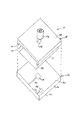
本発明の第1実施例を示す図1〜図5を参照するに、本発明の第1実施例は、基底基板16および透過膜18を有するアクチュエータ12を含んでいる。ベース16は、バルブ本体10を形成するようにハウジング14に結合される。
1 to 5 showing the first embodiment of the present invention, the first embodiment of the present invention includes an
ベース16は、示されるように上面20および下面22を有する概ね平板状の部材である。さらなる実施例において上面20は、特にそのバルブの設計上の要求に対応するように湾曲され、または、カーブがつけられ得るが、図1に示される実施例においては、上面20は、概ね平面である。電極24および対電極26は、ベース16の上面20に結合されている。本発明の好ましい実施例において、電極24および26は、十分な間隔をもって互いに離隔され、もっと詳細に後述されるように透過膜18における選択された領域に電荷をもたらす。電極24および26は、それぞれ、リード25および27により適当な電源に接続される。代替的に、電極24および26は、その分野において知られる配線または他の適切な電気回路により電源に接続され得る。
The
電極24および26は、アクチュエータ12の使用中、安全な位置で電極を維持するようにベース16に接合される電気導電性金属で作られている。好ましい実施例において、電極24および26は、電気部品および電気回路の知られた製造方法により作られ、ベース16に固定される。それらの電極は、代表的には、集積回路を製造するために通常使用されるフォトリソグラフィーの方法により作られる。
図1〜図5の実施例において、単一の電極24および単一の対電極26は、ベース16に設けられている。いくつかの電極および対電極は、アクチュエータ12の特定の必要条件に依存して使用され得ることは理解されるだろう。絶縁層29、即ち、不動態化層は、電極24および対電極26上に露出した部分を形成するようにベース16および電極24の一部に施される。透過膜18は、知られた方法でベース16と、電極24および電極26とに接合されている。本発明の好ましい実施例において、透過膜18は、電極16、電極24および26上に積層または直接的に形成される透水膜である。示される実施例において、透過膜18は、ベース12のかなりの部分に重なるように寸法を有している。好ましくは、透過膜18は、電極24および対電極26の露出部分を完全に覆うように寸法を有している。
1 to 5, a
図2に示されるように、透過膜18は、第1の大きな部分28および大きな部分28と一体に形成される第2の小さな部分30を有している。透過膜18の小さな部分30は、電極24の露出部分に重なり、大きな部分28の厚さより大なる厚さを有する透過膜18の中央に、厚くした部分を形成する。好ましい実施例において、第1の大きな部分28は、ベース16、電極24および26と同一の広がりをもっている。透過膜18の第2の小さな部分30は、電極24を覆うような寸法を有する。本発明における好ましい実施例において、電気的な絶縁層29は、電極24を包囲し、電極24と対電極26とを絶縁するように含まれている。
さらなる実施例においては、その透過膜18が、ベース16全体に渡って均一な厚さで作られてもよい。
As shown in FIG. 2, the
In a further embodiment, the
バルブハウジング14は、図1〜5に示される上壁34を含み、概ね平坦な構成をもった外面36を有している。好ましくは、バルブハウジング14および上壁34は、ベース12の外寸法を補完する寸法を有している。上壁34は、その相対向する外縁38から下方に向けて延在する脚部36を含んでいる。脚部36は、ベース12の外縁38に結合される外縁40を有し、ベース12から上壁34までの長さを有している。脚部36は、上壁34と透過膜18との間の流体用の溝44を形成するように寸法を有している。その流体用溝44の寸法は、膜18の変形量により決定される。代表的には、上壁34は、膜が弛緩した状態の場合、約3〜6ミクロンの距離、膜18から離れている。開口46は、外面36と内面48との間に広がる上壁34内に設けられている。開口46は、好ましくは、電極24のすぐ上に配置される。示される実施例において、上壁34は、上壁34に結合され、開口46を取り囲み、バルブ10の溝44からの流体を導く環状のコラム50を含んでいる。
The
図1〜図3の実施例において、バルブ10の溝44は、第1の入口端52および第2の出口端54で開口し、バルブ10内に延在する連続した流路をもたらす。
第1の開口端52は、パイプまたは他の適当な導管により流体源に連結される流体用の入口を形成する。溝44は、第2の端部54までバルブ10内を完全に貫通している。それにより、流体が第2の出口用開口のような他の位置に導かれる。代替的に、第2の端部54は、流体を必要とされる位置に導くようにパイプまたは導管に連結され得る。
In the embodiment of FIGS. 1-3, the
The first
一実施例において、マイクロバルブ10は、図1Aに示されるような薬物の注入装置56内に内臓され得る。薬物の注入装置56は、導管60によりマイクロバルブ10に連結される薬物用貯留槽58を含んでいる。導管60は、適当な流体継手により入口端52に接続されている。コラム50は、流体を送出装置64に導く導管62に接続されている。電源66は、バルブ10を作動させるための電極24および26に接続されている。コントローラ68は、選択的に電流を電極24および26に供給するように電源66に接続される。電源66は、必要に応じて正または負の電流を電極24に、選択された間隔で所定期間、供給できる直流(DC)電源である。
In one example, the
透過膜18は、好ましくは、ヒドロゲル材料のような透水膜である高分子材料である。適切なヒドロゲル材料は、アガロース、および、ポリアクリルアミドポリマーを含む。電極24に印加された電荷が、透過膜18における変形を生じさせることはわかった。好ましい実施例において、正の電流が電極24に供給され、従って、該電極が陽極として作動する場合、電極24に接触する透過膜18の部分69が、正の電荷を得ながら電極24に対し垂直に収縮する。この膜の収縮は、膜の厚さの減少と伴っている。その後、その電流が遮断される場合、透過層内に電荷があると、その膜が、透過膜18の平面に対し垂直の方向に膨張する。
The
透過膜18における膨張量、即ち、膨張の程度は、ポリマーの性質および組成、透過膜18に供給される電流の強さおよび極性、電流の供給される期間、透過膜の厚さにより、決定される。電極の電気的な励起が、その膜内に電荷、またはイオンを生じさせ、電流が停止した場合、電荷が静電気の斥力を生じるように作用し、垂直方向の膨張をもたらすと考えられる。代表的には、その膜は、約1〜6ミクロン膨張する。
The amount of expansion in the
完全に理解されているわけではないが、そのメカニズムは、電極24に負の電位が加えられるとき、アニオン種の同様な発生によるアニオン媒介性パームレイヤーの膨張にも適用され得ると考えられる。さらに実施例において、また、帯電した種(双極性、陽イオン、または負イオンのコモノマー等)を含む透過層は、電極24における反対の電荷の電位に従う期間およびときにおいて、容易く収縮せしめられ得ると考えられる。同様に、その透過層は、同じ電荷の電位に従う期間およびとき、膨張せしめられる。
Although not fully understood, it is believed that the mechanism can also be applied to the expansion of anion-mediated palm layers due to similar generation of anionic species when a negative potential is applied to
図面を参照するに、透過膜18は、出口用開口46が開き、流体が溝44を通過でき、開口46を通じて出るように通常、弛緩状態にある。正の電荷は、電極24に加えられる。一方、負の電荷が、数ミリ秒から数分までの期間、対電極26に加えられる。電気的な対処が終了するとき、透過膜18は、部分69で膨張し、図4に示されるように突起70を形成する。電極24および開口46は、突起70が膨張し開口46を閉鎖し流体流れを妨害するように配置されている。正の電荷は、短期間、加えられて遮断され、膜18が膨張し完全に開口46を閉鎖し得ることがわかった。電流が遮断されるとき、透過膜の変形は、開口46がこの期間閉鎖されたままであるようにある期間そのままであることがわかった。透過膜の変形は、透過膜18の組成および電流次第で数分から数時間の間そのままである。このようにして、電流は、バルブ10を閉鎖状態に維持するように断続的に加えられ得る。透過膜18は、電流が遮断された後、最終的に弛緩状態に戻るだろう。
Referring to the drawings, the
共有結合、または層に単純に捕捉されるカチオン種の存在などの透過層の種類および組成次第で、電極24に加えられる負の電荷が、帯電した部分の収縮を生じさせ、透過膜18の厚さを減少させると考えられる。このようにして、断続的な正の電荷は、電極24に加えられると、透過膜を変形させ、バルブ10を閉じる。負の電荷が、加えられると、透過膜18がその最初の形状に収縮または弛緩し、バルブ10を開ける。好ましい実施例において、制御装置68は、必要に応じてバルブ10を開閉するために正または負の電荷を加えるように選択的に電源66を作動させることができる。
Depending on the type and composition of the permeable layer, such as covalent bonds or the presence of cationic species that are simply trapped in the layer, the negative charge applied to the
バルブ10は、好ましくは、約1.5cm×約1.5cm未満の外寸を有するマイクロバルブである。バルブ10の実際の寸法は、使用目的次第で変更できる。図1〜5における実施例において、いくつもの出口および電極が設けられ得るが、単一の出口用開口が示されている。
The
アクチュエータ12およびハウジング14は、好ましくは、バルブ10の最終の形状および寸法を作り出すように超小型電気機械の方法(MEMS)により製造される。バルブ10は、シリコン、ガラス、二酸化珪素、プラスチック、またはセラミック材料などのような様々な材料で作られ得る。
アクチュエータ12は、Nanogen, Incにより製造され、その全体が本明細書の一部を構成する米国特許第6051380号公報に開示される“バイオチップ”に実質的に類似した構造を有している。示される実施例において、アクチュエータ12は、略正方形の電極24を有する電極パッドである。電極は、望み通りに円形または長方形であってもよい。電極の大きさは、約5ミクロンから約500ミクロンまでの範囲を有する。代表的には、電極24は、製造技術次第で約10ミクロンから約100ミクロンの範囲を有する。
電極は、その分野で知られたマイクロリソグラフィーおよび/またはマイクロマシン技術により製造され得る。使用され得る他の技術は、電子線リソグラフィー、イオンビームリソグラフィー、および、分子線エピタキシーを含む。電極24は、基本的に、基材に金属層を適切な方法で張り付けることにより製造される。使用される実際の方法は、基材および張り付けられる特定の金属次第であろう。
The electrodes can be manufactured by microlithography and / or micromachine techniques known in the art. Other techniques that can be used include electron beam lithography, ion beam lithography, and molecular beam epitaxy. The
フォトレジスト層が、付けられ、電極の所望の形状が過剰金属をエッチングすることにより、作られる。残った金属が、超小型電極部位として機能する。超小型電極を作るために適した金属および他の材料は、アルミウム、銅、炭素、鉄、銀、金、パラジウム、プラチナ、および、インジウム錫酸化物を含む。代表的に、絶縁材料は、超小型電極を互いに分離するように施される。適切な絶縁材料は、限定されるわけではないが、二酸化ケイ素、窒化ケイ素、ガラス、レジスト材料、ポリアミド、ゴム、プラスチック、セラミック材料を含む。 A photoresist layer is applied and the desired shape of the electrode is made by etching excess metal. The remaining metal functions as a micro electrode part. Suitable metals and other materials for making microelectrodes include aluminum, copper, carbon, iron, silver, gold, palladium, platinum, and indium tin oxide. Typically, the insulating material is applied to separate the microelectrodes from each other. Suitable insulating materials include, but are not limited to, silicon dioxide, silicon nitride, glass, resist material, polyamide, rubber, plastic, ceramic material.
酸化金属層は、超小型電極上に施され、即ち、形成され得るものであり、透過層18の結合のための基材をもたらす。単独あるいは結合した金属酸化物およびヒドロキシル基、ならびに、他の知られた材料は、超小型電極に透過層を付けるための共通結合の部位をもたし得る。いくつかの用途において、共有結合され超小型電極の表面に取り付けられた透過層を有することが望ましい。他の実施例において、透過層は、透過層の物理的な被膜により施され得る。例えば、プラチナまたは金で作られた超小型電極は、透過膜で覆われてもよい。
The metal oxide layer can be applied or formed on the microelectrode and provides a substrate for bonding of the
本発明における一つの実施例において、アクチュエータ12は、標準的なマスクデザインおよび標準的なマイクロリソグラフィー技術により製造される。基底基板は、代表的には、約0.5mmの厚さを有する1から2cmまでの正方のシリコンウェーハである。そのシリコンウェーハは、1から2ミクロンまでの厚さの二酸化ケイ素の絶縁被膜で先ず保護被覆されている。その二酸化ケイ素は、プラズマ強化化学蒸着法(PECVD)により施され得る。
In one embodiment of the present invention, the
アルミニウムのような金属層は、真空蒸着により蒸着され、約0.2ミクロンから0.5ミクロンまでの厚さの層を形成する。または、その金属層は、スパッタリング技術により付けられる。様々な方法および材料が、基材に対する金属層の接合を強化するように基材に適用され得る。ポジタイプのフォトレジストは、それから、付けられ、所望の電極形状でマスキングが行われる。フォトレジスト層は、露光および現像される。光可溶化されたレジストは、除去され、露出された金属層は、所望されるパターンを作るようにエッチングされる。 A metal layer such as aluminum is deposited by vacuum evaporation to form a layer having a thickness of about 0.2 microns to 0.5 microns. Alternatively, the metal layer is applied by a sputtering technique. Various methods and materials can be applied to the substrate to enhance the bonding of the metal layer to the substrate. A positive type photoresist is then applied and masked with the desired electrode shape. The photoresist layer is exposed and developed. The light solubilized resist is removed and the exposed metal layer is etched to produce the desired pattern.
約0.2ミクロンから0.4ミクロンまでの厚さの二酸化ケイ素の層に次いで載せられる0.1ミクロンから0.2ミクロンまでの窒化ケイ素(Si3N4)は、その基材に施される。その基材は、それから、ポジタイプのフォトレジストで覆われ、電極用にマスキングされ、露出されて現像される。その光可溶化されたレジストは、除去され、その二酸化ケイ素および窒化ケイ素層は、電極を露出させるようにエッチングされる。 0.1 micron to 0.2 micron silicon nitride (Si 3 N 4 ), which is then placed on a layer of silicon dioxide about 0.2 to 0.4 microns thick, is applied to the substrate. The The substrate is then covered with a positive type photoresist, masked for electrodes, exposed and developed. The photosolubilized resist is removed and the silicon dioxide and silicon nitride layers are etched to expose the electrodes.
その透過膜は、それから、露出された電極に張り付けられる。透過膜を張り付けるために使用され得るその設計および技術は、綿織物(ローン)、織り布(メッシュ)、多孔質体を含んでいる。その透過膜は、約10ミクロンから30ミクロンの厚さの層を有している。ひとつの実施例において、修飾親水性ゲルは、基材内の空孔を満たすように20%から35%までのポリアクリルアミド、0.1%のポリリシンを含むものが施される。この材料は、約2nmから約10nmまでの空孔精度をもってゲル状の被膜を形成する。その透過膜により、その電極がDCモードで役立つことができ、小さな対イオンがその透過膜を通過できる。 The permeable membrane is then affixed to the exposed electrode. The designs and techniques that can be used to apply the permeable membrane include cotton fabrics (lawns), woven fabrics (mesh), and porous bodies. The permeable membrane has a layer about 10 to 30 microns thick. In one embodiment, the modified hydrophilic gel is applied with 20% to 35% polyacrylamide, 0.1% polylysine to fill the voids in the substrate. This material forms a gel-like film with pore accuracy from about 2 nm to about 10 nm. The permeable membrane allows the electrode to serve in DC mode and allows small counter ions to pass through the permeable membrane.
ローンタイプの透過膜は、その表面から垂直方向に直線状分子、またはポリマーの配列を含んでいる。これらの構造は、分子間の最小の橋かけで親和性ポリマー分子を金属表面に付けることにより形成される。 A lawn-type permeable membrane includes an array of linear molecules or polymers perpendicular to the surface. These structures are formed by attaching affinity polymer molecules to the metal surface with minimal crosslinking between the molecules.
メッシュタイプの透過膜は、ポリマー分子の不規則な配列により形成される。その分子は、橋かけの程度により決定される平均空孔サイズを有するメッシュ状構造を形成する。これらの構造は、ヒドロゲル型の材料で作られ得る。適した材料の例としては、アガロース、グリオキシルアガロース、ポリアクリルアミド、ポリメタクリルアミド、ポリアクリラート、ポリメタクリレートおよびそれらのコポリマーからなる群から選択されたポリマーを含む。重合、および架橋された他の生物学的材料または非生物学的材料は、使用され得る。一般に、ポリマーは、ビニルモノマー(vinylic monomers)で作られる。これらの材料は、その基材の表面上にスピンコーティングにより施される。本発明の他の実施例において、透過膜は、帯電しているポリマー、または、電界を受けるとき、電荷を捕捉できるポリマーで作られ得る。 The mesh type permeable membrane is formed by an irregular arrangement of polymer molecules. The molecules form a mesh-like structure with an average pore size determined by the degree of crosslinking. These structures can be made of hydrogel type materials. Examples of suitable materials include polymers selected from the group consisting of agarose, glyoxyl agarose, polyacrylamide, polymethacrylamide, polyacrylate, polymethacrylate and copolymers thereof. Other biological or non-biological materials that are polymerized and crosslinked can be used. In general, the polymers are made of vinyl monomers. These materials are applied by spin coating on the surface of the substrate. In other embodiments of the present invention, the permeable membrane can be made of a charged polymer or a polymer that can trap charge when subjected to an electric field.
ポアタイプの透過膜は、透過膜の表面形式で電極パッドに溝または孔を直接に形成する材料を使用する。適した材料の例としては、ポリカーボネイト、ポリスルホン、およびガラス材料などを含む。この形式の透過膜は、物理的および化学的に金属表面に固定されなければならない。 The pore type permeable membrane uses a material that directly forms grooves or holes in the electrode pad in the form of the surface of the permeable membrane. Examples of suitable materials include polycarbonate, polysulfone, and glass materials. This type of permeable membrane must be physically and chemically fixed to the metal surface.
ハウジング14は、同様なマイクロマシンまたはフォトリソグラフィーの方法により形成され得る。ハウジング14の脚部36は、リソグラフィーまたは機械加工により形成され得る。代替的に、脚部36は、適切な技術により上壁34に接合される個別の部材として形成されてもよい。脚部36は、超小型機械装置産業において通常使用される知られた接合技術を使って基底16に接合されている。
The
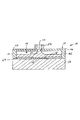
図1〜図5は、その透過膜が変形しバルブ構造において出口用開口に接触し密封する超小型バルブを製造するための本発明に係る一つの実施例を示す。図6に示される本発明における代替的な実施例において、バルブ70は、アクチュエータ72およびハウジング74を含んでいる。アクチュエータ72は、図1〜図5のアクチュエータと実質的に同様であり、基底76、電極パッド78、絶縁層80、および、透過膜82を含む。ハウジング14は、その中を延在する通路86を有する本体部84で作られている。溝88は、出口用溝を形成するように通路86に連通する本体部84の上面に形成されている。上壁90は、溝88および通路86を包囲するように本体部84に取り付けられている。バルブ70は、所定期間、電荷を電極パッド78に加えることによる同様な方法で作動される。その結果、透過膜は、図6の想像線により示されるように、膨張し通路86を閉鎖する。上述の実施例のように、その電流は、バルブ10を選択的に開閉するように反転され得る。
1 to 5 show an embodiment of the present invention for manufacturing a micro-valve whose permeable membrane is deformed to contact and seal an outlet opening in a valve structure. In an alternative embodiment of the present invention shown in FIG. 6,
図7および図8における実施例
図7および図8は、本発明に従うバルブ90の第2の実施例を示す。バルブ90は、図1〜図5における実施例に類似しており、アクチュエータ90およびバルブハウジング94を含んでいる。アクチュエータ92は、上述の実施例と類似しており、ベース95、電極パッド96、および電極パッド96を包囲する絶縁層98を含んでいる。透過膜100は、電極パッド96および絶縁層98上に施されている。
ハウジング94は、下面102および上面104を有している。下面102は、第1の端部108からハウジング94の第2の端部110まで延在する流れ溝106を含んでいる。図7に示されるように、溝106は、透過膜100および電極96の真上に延在している。溝106は、概ね平坦な上面112および真っ直ぐな側壁114で形成されるように示されている。代替的な実施例において、溝106は、V字状の溝を形成するような傾斜した側壁、または、U字状の溝を形成するように湾曲した側壁を有するものでもよい。好ましい実施例において、溝106は、マイクロマシンまたはフォトリソグラフィー法により形成される。従来、溝106を形成するために使用されるその方法は、溝106の最終形状を決定する。例えば、溝106をエッチングするために使用される腐食液が、真っ直ぐな側壁が形成されるか、傾斜した側壁が形成されるかを決定する。
図7および図8において、ハウジング94の下面102は、下面102と透過膜100との間に流体流れがないようにじかにアクチュエータ92に結合される。
代替的な実施例において、下面102は、上述の実施例のように透過膜100から離隔されてもよい。
Example in FIGS. 7 and 8 FIGS. 7 and 8 show a second example of a
The
7 and 8, the
In an alternative embodiment, the
バルブ90は、上述の実施例と同様な方法で作動される。電荷は、電極パッド96に供給されて、透過膜100が図8に想像線により示されるような形状に膨張し、溝106の断面部を埋め、その通路を閉鎖する。上述の実施例のように、電極パッド96に通じる電流を反転させると、透過膜100がその最初の形状に戻り溝106を開く。
The
図9〜図12の実施例
図9〜図12を参照するに、本発明の他の実施例は、アクチュエータ122およびバルブハウジング124を含むバルブアッセンブリ120について述べられる。アクチュエータ122は、上述の実施例と実質的に同様であり、ベース126、電極パッド128、絶縁層130、透過膜132を含む。
バルブハウジング124は、上面138に形成され長手方向の流れ用の溝136を有する本体134を含む。実施例に示される溝136は、概ねU字形を有し、第1の端部140から第2の端部141まで延在している。開口142は、上面138から下面144まで本体134を貫通している。開口142は、図11に示されるように、溝136が開口142の中心を貫通するように溝136と同心とされている。バルブ用部材146は、開口142内に設けられ図9に示される開いた位置と図12に示される閉じた位置との間を往復する。
Embodiment of FIGS. 9-12 Referring to FIGS. 9-12, another embodiment of the present invention is described with respect to a
The
図9および図10を参照するに、バルブ用部材146は、開口142の形状および寸法を相補する側壁148を有する概ね円柱状部材である。バルブ用部材146の下端150は、概ね平坦であり、透過膜132に接触する。上壁152は、開口142の上端および溝136を閉鎖するようにバルブ本体134に結合されている。バルブ用部材146の上端154は、バルブ用部材146が閉じた場合、上壁152に合うように概ね平坦である。
With reference to FIGS. 9 and 10, the
バルブアッセンブリ120は、電流を電極パッド128に供給することにより、透過膜132が図12に示されるように変形し膨張することによって作動される。
透過膜132の膨張が、バルブ部材146を上壁152に向けて押し動かし、溝136を閉じる。示される実施例において、凹部156は、透過膜132の膨張のための逃げ部を形成するようにバルブ本体134の下面144に設けられている。バルブ部材146は、透過膜132の膨張および収縮により開口142内を往復動するように透過膜132に取り付けられ得る。更なる実施例においては、バルブ部材146は、開状態となるように透過膜132に向かって付勢されてもよい。
The
Expansion of the
図13の実施例
図13は、マルチバルブアッセンブリを使用するためのアクチュエータ160の他の実施例を示す。示されるようなアクチュエータ160は、ベース162、および、ベース上から離隔されるいくつかの電極パッド164を含む。この実施例において、二つの対電極166が設けられている。上述の実施例のように、変形可能な透過膜およびバルブハウジング(不図示)が設けられている。得られるバルブは、上述の実施例と同じようにして作動される。
Embodiment of FIG. 13 FIG. 13 shows another embodiment of an
いくつかの実施例が、本発明を説明するために選択されたが、本装置の様々な変更および修正が添付した請求の範囲において定義されたような発明の範囲から逸脱することなくなされ得ることは当業者によって理解されるだろう。 While several embodiments have been selected to illustrate the present invention, various changes and modifications of the apparatus may be made without departing from the scope of the invention as defined in the appended claims. Will be understood by those skilled in the art.
Claims (39)
前記ベースに重なる第1の部分と、前記電極パッドに重なる第2の部分とを備え、縦寸法を有し前記電極パッド上の平坦な透過膜と、
前記電極パッドに対向する領域内の前記透過膜に接触する部材と、を備え、
前記透過膜は、ヒドロゲルポリマーであり、電流が前記電極パッドに供給される場合、該透過膜が前記縦寸法を横切る方向に収縮し、前記電流が遮断される場合、前記電極パッドの領域内で該透過膜から突出する突起を形成するように該透過膜が前記縦寸法を横切る方向に膨張し、それにより、前記部材を該突起によって動かす超小型電気機械装置用アクチュエータ。 An electrode pad provided on the base ;
A first portion that overlaps the base and a second portion that overlaps the electrode pad, and has a vertical dimension and a flat permeable membrane on the electrode pad;
A member in contact with the permeable membrane in a region facing the electrode pad,
The permeable membrane is a hydrogel polymer, and when current is supplied to the electrode pad, the permeable membrane contracts in a direction across the longitudinal dimension, and when the current is interrupted, within the region of the electrode pad. An actuator for a microelectromechanical device, wherein the permeable membrane expands in a direction transverse to the longitudinal dimension so as to form a projection protruding from the permeable membrane , thereby moving the member by the projection .
前記基板に重なる第1の部分と、前記電極パッドに重なる第2の部分とを備え、前記電極パッド上の高分子ヒドロゲルの平坦な透過膜であって、縦寸法を有し、電流が前記電極パッドに供給される場合、該縦寸法を横切る方向に変形可能である透過膜と、
前記透過膜から離隔され、該膜との相互間の流路であって該透過膜が弛緩状態の場合、開口する流路を形成する壁とを含み、
前記透過膜は、電流が前記電極パッドに供給される場合、実質的に前記流路を閉鎖するように該縦寸法を横切る方向に、前記電極パッドにより画定される領域内に突起を形成するように変形可能である超小型バルブ。A base substrate having at least one electrode pad;
A flat permeable membrane of polymer hydrogel on the electrode pad , the first portion overlapping the substrate and the second portion overlapping the electrode pad , wherein the electrode has a vertical dimension, and current is applied to the electrode A permeable membrane that is deformable in a direction across the longitudinal dimension when supplied to the pad;
A wall that is separated from the permeable membrane and is a flow channel between the membrane and the permeable membrane is in a relaxed state, and forms a channel that opens.
The permeable membrane forms a protrusion in a region defined by the electrode pad in a direction transverse to the longitudinal dimension so as to substantially close the flow path when current is supplied to the electrode pad. Ultra-small valve that can be transformed into
該バルブ本体は、前記透過膜に結合される請求項7記載の超小型バルブ。A valve housing and a valve body mounted within the valve body and moving between an open position and a closed position;
The micro valve according to claim 7, wherein the valve body is coupled to the permeable membrane.
少なくとも一つの電極パッドを備える基底基板と、該基板に重なる第1の部分と、該電極パッドに重なる第2の部分とを有し、該電極パッド上の変形可能なヒドロゲルの平坦な透過膜と、該透過膜との間の流路であって該透過膜が弛緩状態の場合、開口する流路を形成するように該透過膜から離隔される壁とを有する超小型バルブアッセンブリを設けるステップと、
電流を前記電極パッドに十分な期間供給し、それから、該電流を遮断し、前記電極パッドの領域内の前記透過膜から突出する突起を形成するように前記透過膜を膨張させ、該流路を該突起により閉じるステップと、
を含んでなる方法。A method of operating a valve assembly of a micro fluidic device, comprising:
A base substrate comprising at least one electrode pad, a first portion overlying the substrate, and a second portion overlying the electrode pad, and a deformable hydrogel flat permeable membrane on the electrode pad; Providing a micro valve assembly having a channel between the permeable membrane and a wall spaced from the permeable membrane to form an open channel when the permeable membrane is in a relaxed state; ,
Supplying a current to the electrode pad for a sufficient period of time , then interrupting the current and inflating the permeable membrane to form a protrusion protruding from the permeable membrane in the region of the electrode pad ; A step of closing by the protrusion ;
Comprising a method.
前記基板に重なる第1の部分と、前記電極パッドに重なる第2の部分とを備え、縦寸法を有し、電流が前記電極パッドに供給される場合、該縦寸法を横切る方向に変形可能とされる前記電極パッド上の平坦な高分子透過膜と、
前記電極パッドに接続され、所定の期間、正または負の電荷を選択的に該電極パッドに供給するためのコントローラを含む直流電源と、
前記透過膜から離隔され、該膜との間に流路を形成する壁とを含み、該透過膜は、
電流が前記電極パッドに供給され、該電流が遮断されるとき、前記電極パッドの領域における該透過膜から突出する突起を形成するように該透過膜を膨張させ、実質的に該流路を該突起により閉鎖する場合、変形可能であり、
前記直流電源の前記コントローラは、前記透過膜の変形状態を維持するように前記電極パッドに断続的に前記電荷を供給する超小型バルブ。A base substrate having at least one electrode pad;
A first portion that overlaps the substrate and a second portion that overlaps the electrode pad have a vertical dimension and can be deformed in a direction across the vertical dimension when current is supplied to the electrode pad. A flat polymer permeable membrane on the electrode pad;
A DC power source including a controller connected to the electrode pad and selectively supplying positive or negative charge to the electrode pad for a predetermined period;
A wall that is spaced apart from the permeable membrane and forms a flow path between the permeable membrane and the permeable membrane,
When a current is supplied to the electrode pad and the current is interrupted, the permeable membrane is inflated to form a protrusion protruding from the permeable membrane in the region of the electrode pad , substantially passing the flow path Can be deformed when closed by protrusions ,
The miniature valve, wherein the controller of the DC power supply intermittently supplies the electric charge to the electrode pad so as to maintain the deformed state of the permeable membrane.
少なくとも一つの電極パッドを備える基底基板と、該基板における第1の部分、および、該電極パッド上の第2の部分を有する変形可能な透過膜と、該透過膜との間に流路を形成するように該透過膜から離隔される上壁とを有する超小型バルブアッセンブリを設け、該透過膜は、前記流路を閉鎖するように電流が遮断後、ある期間、該電極パッドにおける領域内に突起を形成し、変形したままであるステップと、
突起を形成するように前記透過膜を膨張させ、該流路を該突起により閉じるように変形した状態で該透過膜を維持するように、所定の間隔および十分な期間、電流を前記電極パッドに供給するステップと、
を含んでなる方法。A method of operating a valve assembly of a micro fluidic device, comprising:
A base plate having at least one electrode pad, a deformable permeable membrane having a first portion on the substrate, and a second portion on the electrode pad, and a flow path formed between the permeable membrane A micro valve assembly having an upper wall spaced apart from the permeable membrane so that the permeable membrane is within a region of the electrode pad for a period of time after the current is interrupted to close the flow path. Forming a protrusion and remaining deformed;
The permeable membrane is expanded so as to form a protrusion, and a current is applied to the electrode pad for a predetermined interval and for a sufficient period so as to maintain the permeable membrane in a state where the flow path is closed by the protrusion. Supplying step;
Comprising a method.
Applications Claiming Priority (2)
| Application Number | Priority Date | Filing Date | Title |
|---|---|---|---|
| US09/790,530 US6626417B2 (en) | 2001-02-23 | 2001-02-23 | Microfluidic valve and microactuator for a microvalve |
| PCT/US2002/005222 WO2002068849A1 (en) | 2001-02-23 | 2002-02-22 | Microfluidic valve and microactuator for a microvalve |
Publications (3)
| Publication Number | Publication Date |
|---|---|
| JP2004526913A JP2004526913A (en) | 2004-09-02 |
| JP2004526913A5 JP2004526913A5 (en) | 2005-12-22 |
| JP4383053B2 true JP4383053B2 (en) | 2009-12-16 |
Family
ID=25150974
Family Applications (1)
| Application Number | Title | Priority Date | Filing Date |
|---|---|---|---|
| JP2002567724A Expired - Lifetime JP4383053B2 (en) | 2001-02-23 | 2002-02-22 | Micro fluid valve and micro actuator for micro valve |
Country Status (5)
| Country | Link |
|---|---|
| US (1) | US6626417B2 (en) |
| EP (1) | EP1379802A4 (en) |
| JP (1) | JP4383053B2 (en) |
| CA (1) | CA2438810C (en) |
| WO (1) | WO2002068849A1 (en) |
Families Citing this family (44)
| Publication number | Priority date | Publication date | Assignee | Title |
|---|---|---|---|---|
| CA2299131C (en) * | 1999-02-23 | 2003-11-11 | Matsushita Electric Works, Ltd. | Semiconductor device |
| AU2002303933A1 (en) * | 2001-05-31 | 2002-12-09 | Rochester Institute Of Technology | Fluidic valves, agitators, and pumps and methods thereof |
| WO2003040541A1 (en) * | 2001-11-08 | 2003-05-15 | Siemens Vdo Automotive Inc. | Electro-active polymer as a fuel vapor control valve actuator |
| TW551387U (en) * | 2002-04-22 | 2003-09-01 | Ind Tech Res Inst | Water gel actuated micro pump |
| US7648619B2 (en) * | 2002-06-04 | 2010-01-19 | Industrial Technology Research | Hydrogel-driven micropump |
| DE102004008008B4 (en) * | 2003-12-23 | 2016-02-04 | Robert Bosch Gmbh | Integrated flow sensor for measuring fluid flow and method of manufacturing a flow sensor |
| US20050211937A1 (en) * | 2003-12-29 | 2005-09-29 | Popadiuc Peter O | Method of sealing machine components |
| US8581308B2 (en) | 2004-02-19 | 2013-11-12 | Rochester Institute Of Technology | High temperature embedded charge devices and methods thereof |
| US20050196321A1 (en) * | 2004-03-03 | 2005-09-08 | Zhili Huang | Fluidic programmable array devices and methods |
| JP2008537063A (en) * | 2005-01-31 | 2008-09-11 | プレジデント・アンド・フエローズ・オブ・ハーバード・カレツジ | Valves and reservoirs for microfluidic systems |
| US20070023719A1 (en) * | 2005-07-27 | 2007-02-01 | Shannon Mark A | Bi-direction rapid action electrostatically actuated microvalve |
| US8628055B2 (en) | 2005-07-27 | 2014-01-14 | The Board Of Trustees Of The University Of Illinois | Bi-direction rapid action electrostatically actuated microvalve |
| US8123834B2 (en) | 2005-10-06 | 2012-02-28 | The Board Of Trustees Of The University Of Illinois | High gain selective metal organic framework preconcentrators |
| WO2007044690A2 (en) * | 2005-10-07 | 2007-04-19 | The General Hospital Corporation | Devices and methods for cell manipulation |
| US7913928B2 (en) | 2005-11-04 | 2011-03-29 | Alliant Techsystems Inc. | Adaptive structures, systems incorporating same and related methods |
| EP2111551A1 (en) * | 2006-12-20 | 2009-10-28 | Applied Biosystems, LLC | Devices and methods for flow control in microfluidic structures |
| US7871570B2 (en) * | 2007-02-23 | 2011-01-18 | Joseph Zhili Huang | Fluidic array devices and systems, and related methods of use and manufacturing |
| WO2008124046A1 (en) * | 2007-04-04 | 2008-10-16 | Micropoint Bioscience Inc.. | Micromachined electrowetting microfluidic valve |
| US8123841B2 (en) | 2008-01-16 | 2012-02-28 | The Board Of Trustees Of The University Of Illinois | Column design for micro gas chromatograph |
| US8269029B2 (en) | 2008-04-08 | 2012-09-18 | The Board Of Trustees Of The University Of Illinois | Water repellent metal-organic frameworks, process for making and uses regarding same |
| US20100059120A1 (en) * | 2008-09-11 | 2010-03-11 | General Electric Company | Microfluidic device and methods for droplet generation and manipulation |
| DE102008048064A1 (en) * | 2008-09-19 | 2010-04-08 | Jobst Technologies Gmbh | Microfluidic valve, microfluidic pump, microfluidic system and a manufacturing process |
| EP2367634A1 (en) | 2008-12-24 | 2011-09-28 | Heriot-Watt University | A microfluidic system and method |
| IT1398480B1 (en) | 2009-12-17 | 2013-03-01 | Silicon Biosystems Spa | MICROFLUID SYSTEM |
| GB2481425A (en) | 2010-06-23 | 2011-12-28 | Iti Scotland Ltd | Method and device for assembling polynucleic acid sequences |
| DE102010061909A1 (en) * | 2010-11-24 | 2012-05-24 | Fraunhofer-Gesellschaft zur Förderung der angewandten Forschung e.V. | Fluidic actuator with deformable closure arrangement and long shelf life |
| US9162226B2 (en) | 2011-05-12 | 2015-10-20 | The United States Of America, As Represented By The Secretary Of Commerce | Foldable microfluidic devices using double-sided tape |
| WO2012170068A2 (en) * | 2011-06-05 | 2012-12-13 | University Of British Columbia | Wireless microactuators and control methods |
| US20130032210A1 (en) * | 2011-08-02 | 2013-02-07 | Teledyne Dalsa Semiconductor, Inc. | Integrated microfluidic device with actuator |
| US8975193B2 (en) | 2011-08-02 | 2015-03-10 | Teledyne Dalsa Semiconductor, Inc. | Method of making a microfluidic device |
| US20150014557A1 (en) * | 2012-01-31 | 2015-01-15 | Jatco Ltd. | Automatic transmission control valve body structure |
| FR2987282B1 (en) * | 2012-02-24 | 2017-12-29 | Fonds De L'espci Georges Charpak | MICROCANAL WITH OPENING AND / OR CLOSING AND / OR PUMPING DEVICE |
| US9493228B2 (en) * | 2012-11-28 | 2016-11-15 | The Boeing Company | High heat transfer rate reusable thermal protection system |
| JP6673820B2 (en) | 2013-03-14 | 2020-03-25 | ザ ボード オブ トラスティーズ オブ ザ レランド スタンフォード ジュニア ユニバーシティー | Capillary barrier for gradual loading of microfluidic devices |
| US20180257069A1 (en) * | 2015-09-16 | 2018-09-13 | Technion Research & Development Foundation Limited | Dynamic microfluidic devices and use thereof |
| AU2017212754B2 (en) | 2016-01-29 | 2023-06-29 | Purigen Biosystems, Inc. | Isotachophoresis for purification of nucleic acids |
| JP6654951B2 (en) * | 2016-03-31 | 2020-02-26 | 株式会社エンプラス | Fluid handling device |
| CN110291396B (en) * | 2016-10-07 | 2021-02-26 | 刘新宇 | Microfluidic analytical platform for autonomous immunoassays |
| SG11202000871WA (en) | 2017-08-02 | 2020-02-27 | Purigen Biosystems Inc | Systems, devices, and methods for isotachophoresis |
| US11331618B2 (en) * | 2018-03-07 | 2022-05-17 | Encite Llc | R2R microelectromechanical gas concentrator |
| JP7071641B2 (en) * | 2018-10-18 | 2022-05-19 | 日本電信電話株式会社 | Laminates, method of manufacturing laminates and shape control devices |
| CN109695779B (en) * | 2019-01-25 | 2020-07-31 | 京东方科技集团股份有限公司 | Fluid switch valve, preparation method and control method thereof, and microfluidic device |
| US11236846B1 (en) * | 2019-07-11 | 2022-02-01 | Facebook Technologies, Llc | Fluidic control: using exhaust as a control mechanism |
| TWI755075B (en) * | 2020-09-25 | 2022-02-11 | 研能科技股份有限公司 | Miniature fluid transportation device |
Family Cites Families (24)
| Publication number | Priority date | Publication date | Assignee | Title |
|---|---|---|---|---|
| US4581624A (en) * | 1984-03-01 | 1986-04-08 | Allied Corporation | Microminiature semiconductor valve |
| US4966646A (en) | 1986-09-24 | 1990-10-30 | Board Of Trustees Of Leland Stanford University | Method of making an integrated, microminiature electric-to-fluidic valve |
| CA2069894C (en) * | 1990-08-31 | 2001-04-24 | Harald T. G. Van Lintel | Valve equipped with a position detector and a micropump incorporating said valve |
| US5058856A (en) * | 1991-05-08 | 1991-10-22 | Hewlett-Packard Company | Thermally-actuated microminiature valve |
| US6051380A (en) | 1993-11-01 | 2000-04-18 | Nanogen, Inc. | Methods and procedures for molecular biological analysis and diagnostics |
| DE4234237C2 (en) | 1992-10-10 | 2000-11-30 | Bosch Gmbh Robert | Temperature compensated micro actuator |
| US5309943A (en) | 1992-12-07 | 1994-05-10 | Ford Motor Company | Micro-valve and method of manufacturing |
| US5378583A (en) | 1992-12-22 | 1995-01-03 | Wisconsin Alumni Research Foundation | Formation of microstructures using a preformed photoresist sheet |
| US5338416A (en) | 1993-02-05 | 1994-08-16 | Massachusetts Institute Of Technology | Electrochemical etching process |
| ATE156895T1 (en) | 1993-05-27 | 1997-08-15 | Fraunhofer Ges Forschung | MICRO VALVE |
| US6071394A (en) | 1996-09-06 | 2000-06-06 | Nanogen, Inc. | Channel-less separation of bioparticles on a bioelectronic chip by dielectrophoresis |
| US5788468A (en) | 1994-11-03 | 1998-08-04 | Memstek Products, Llc | Microfabricated fluidic devices |
| AU7671696A (en) * | 1996-01-18 | 1997-08-11 | University Of New Mexico | Soft actuators and artificial muscles |
| US5785295A (en) * | 1996-08-27 | 1998-07-28 | Industrial Technology Research Institute | Thermally buckling control microvalve |
| US5865417A (en) * | 1996-09-27 | 1999-02-02 | Redwood Microsystems, Inc. | Integrated electrically operable normally closed valve |
| US5971355A (en) | 1996-11-27 | 1999-10-26 | Xerox Corporation | Microdevice valve structures to fluid control |
| US6123316A (en) * | 1996-11-27 | 2000-09-26 | Xerox Corporation | Conduit system for a valve array |
| KR100356101B1 (en) * | 1996-12-04 | 2003-01-14 | 우릴크 로보우 | Method for disinfection or sterilization of foods such as meat and vegetable products or produce, of feeding stuffs, machinery and equipment for foods and feeding stuff production, and a technical plant designed to carry out the method |
| US5796152A (en) | 1997-01-24 | 1998-08-18 | Roxburgh Ltd. | Cantilevered microstructure |
| US5780748A (en) | 1997-01-29 | 1998-07-14 | Hewlett-Packard Company | Flow device having parallel flow surfaces which move toward and away from one another to adjust the flow channel in proportion to applied force |
| US6072509A (en) * | 1997-06-03 | 2000-06-06 | Eastman Kodak Company | Microfluidic printing with ink volume control |
| US5965410A (en) | 1997-09-02 | 1999-10-12 | Caliper Technologies Corp. | Electrical current for controlling fluid parameters in microchannels |
| US5993414A (en) | 1998-04-23 | 1999-11-30 | Medtronic, Inc. | Implantable device |
| US6056269A (en) * | 1999-01-15 | 2000-05-02 | Hewlett-Packard Company | Microminiature valve having silicon diaphragm |
-
2001
- 2001-02-23 US US09/790,530 patent/US6626417B2/en not_active Expired - Fee Related
-
2002
- 2002-02-22 CA CA002438810A patent/CA2438810C/en not_active Expired - Fee Related
- 2002-02-22 JP JP2002567724A patent/JP4383053B2/en not_active Expired - Lifetime
- 2002-02-22 EP EP02707838A patent/EP1379802A4/en not_active Withdrawn
- 2002-02-22 WO PCT/US2002/005222 patent/WO2002068849A1/en active Application Filing
Also Published As
| Publication number | Publication date |
|---|---|
| US20020117643A1 (en) | 2002-08-29 |
| CA2438810A1 (en) | 2002-09-06 |
| CA2438810C (en) | 2009-06-02 |
| EP1379802A1 (en) | 2004-01-14 |
| EP1379802A4 (en) | 2005-11-02 |
| WO2002068849A1 (en) | 2002-09-06 |
| WO2002068849A9 (en) | 2003-01-30 |
| WO2002068849A8 (en) | 2004-05-21 |
| US6626417B2 (en) | 2003-09-30 |
| JP2004526913A (en) | 2004-09-02 |
Similar Documents
| Publication | Publication Date | Title |
|---|---|---|
| JP4383053B2 (en) | Micro fluid valve and micro actuator for micro valve | |
| JP5196422B2 (en) | Selective bonding for microvalve formation | |
| US7052594B2 (en) | Devices and methods for controlling fluid flow using elastic sheet deflection | |
| US7090471B2 (en) | Integrated electrostatic peristaltic pump method and apparatus | |
| JP4704398B2 (en) | Micro electromechanical system valve and manufacturing method thereof | |
| US5725363A (en) | Micromembrane pump | |
| US5336062A (en) | Microminiaturized pump | |
| CA2320458C (en) | Mems variable optical attenuator | |
| KR100610908B1 (en) | Electrically operated integrated microvalve | |
| US6255757B1 (en) | Microactuators including a metal layer on distal portions of an arched beam | |
| EP0949418B1 (en) | Micro-pump and micro-pump manufacturing method | |
| US6056269A (en) | Microminiature valve having silicon diaphragm | |
| EP0469749A1 (en) | Control valve utilizing mechanical beam buckling | |
| US7011288B1 (en) | Microelectromechanical device with perpendicular motion | |
| DK2556282T3 (en) | Microvalve with valve elastically deformable lip, the preparation method and micropump | |
| JP2004526913A5 (en) | ||
| CN106996477B (en) | Two-stage fluid control valve with first stage mechanical valve and second stage microvalve | |
| Hesketh et al. | Microvalve for fuel cells and miniature gas chromatographic system | |
| JP4529814B2 (en) | Micro valve | |
| JP4529619B2 (en) | Micro valve | |
| WO2002018756A1 (en) | Micro-fluidic actuator | |
| US20100327211A1 (en) | Method for the production of micro/nanofluidic devices for flow control and resulting device | |
| JP2004176802A (en) | Microvalve | |
| US11927281B1 (en) | Piezoelectrically-actuated microvalve device and method of fabrication |
Legal Events
| Date | Code | Title | Description |
|---|---|---|---|
| A521 | Written amendment |
Free format text: JAPANESE INTERMEDIATE CODE: A523 Effective date: 20050222 |
|
| A621 | Written request for application examination |
Free format text: JAPANESE INTERMEDIATE CODE: A621 Effective date: 20050222 |
|
| A131 | Notification of reasons for refusal |
Free format text: JAPANESE INTERMEDIATE CODE: A131 Effective date: 20080229 |
|
| A601 | Written request for extension of time |
Free format text: JAPANESE INTERMEDIATE CODE: A601 Effective date: 20080529 |
|
| A602 | Written permission of extension of time |
Free format text: JAPANESE INTERMEDIATE CODE: A602 Effective date: 20080605 |
|
| A601 | Written request for extension of time |
Free format text: JAPANESE INTERMEDIATE CODE: A601 Effective date: 20080626 |
|
| A602 | Written permission of extension of time |
Free format text: JAPANESE INTERMEDIATE CODE: A602 Effective date: 20080703 |
|
| A601 | Written request for extension of time |
Free format text: JAPANESE INTERMEDIATE CODE: A601 Effective date: 20080730 |
|
| A602 | Written permission of extension of time |
Free format text: JAPANESE INTERMEDIATE CODE: A602 Effective date: 20080806 |
|
| A521 | Written amendment |
Free format text: JAPANESE INTERMEDIATE CODE: A523 Effective date: 20080901 |
|
| A131 | Notification of reasons for refusal |
Free format text: JAPANESE INTERMEDIATE CODE: A131 Effective date: 20081010 |
|
| A601 | Written request for extension of time |
Free format text: JAPANESE INTERMEDIATE CODE: A601 Effective date: 20090107 |
|
| A602 | Written permission of extension of time |
Free format text: JAPANESE INTERMEDIATE CODE: A602 Effective date: 20090115 |
|
| A601 | Written request for extension of time |
Free format text: JAPANESE INTERMEDIATE CODE: A601 Effective date: 20090210 |
|
| A602 | Written permission of extension of time |
Free format text: JAPANESE INTERMEDIATE CODE: A602 Effective date: 20090218 |
|
| A521 | Written amendment |
Free format text: JAPANESE INTERMEDIATE CODE: A523 Effective date: 20090410 |
|
| TRDD | Decision of grant or rejection written | ||
| A01 | Written decision to grant a patent or to grant a registration (utility model) |
Free format text: JAPANESE INTERMEDIATE CODE: A01 Effective date: 20090821 |
|
| A01 | Written decision to grant a patent or to grant a registration (utility model) |
Free format text: JAPANESE INTERMEDIATE CODE: A01 |
|
| A61 | First payment of annual fees (during grant procedure) |
Free format text: JAPANESE INTERMEDIATE CODE: A61 Effective date: 20090918 |
|
| FPAY | Renewal fee payment (event date is renewal date of database) |
Free format text: PAYMENT UNTIL: 20121002 Year of fee payment: 3 |
|
| R150 | Certificate of patent or registration of utility model |
Free format text: JAPANESE INTERMEDIATE CODE: R150 |