JP4378651B2 - Distributed MCU (multipoint control unit) - Google Patents
Distributed MCU (multipoint control unit) Download PDFInfo
- Publication number
- JP4378651B2 JP4378651B2 JP2006518565A JP2006518565A JP4378651B2 JP 4378651 B2 JP4378651 B2 JP 4378651B2 JP 2006518565 A JP2006518565 A JP 2006518565A JP 2006518565 A JP2006518565 A JP 2006518565A JP 4378651 B2 JP4378651 B2 JP 4378651B2
- Authority
- JP
- Japan
- Prior art keywords
- connection unit
- end point
- list
- multisite
- site
- Prior art date
- Legal status (The legal status is an assumption and is not a legal conclusion. Google has not performed a legal analysis and makes no representation as to the accuracy of the status listed.)
- Expired - Fee Related
Links
Images


Classifications
-
- H—ELECTRICITY
- H04—ELECTRIC COMMUNICATION TECHNIQUE
- H04N—PICTORIAL COMMUNICATION, e.g. TELEVISION
- H04N7/00—Television systems
- H04N7/14—Systems for two-way working
- H04N7/15—Conference systems
- H04N7/152—Multipoint control units therefor
-
- H—ELECTRICITY
- H04—ELECTRIC COMMUNICATION TECHNIQUE
- H04M—TELEPHONIC COMMUNICATION
- H04M3/00—Automatic or semi-automatic exchanges
- H04M3/42—Systems providing special services or facilities to subscribers
- H04M3/56—Arrangements for connecting several subscribers to a common circuit, i.e. affording conference facilities
- H04M3/562—Arrangements for connecting several subscribers to a common circuit, i.e. affording conference facilities where the conference facilities are distributed
-
- H—ELECTRICITY
- H04—ELECTRIC COMMUNICATION TECHNIQUE
- H04M—TELEPHONIC COMMUNICATION
- H04M3/00—Automatic or semi-automatic exchanges
- H04M3/42—Systems providing special services or facilities to subscribers
- H04M3/56—Arrangements for connecting several subscribers to a common circuit, i.e. affording conference facilities
- H04M3/567—Multimedia conference systems
Abstract
Description
本発明は、ビデオ・カンファレンス・ネットワーク装置に関し、特に、分散したビデオ・カンファレンス(テレビ会議)において、複数のエンド・ポイントのマルチ・サイト接続ユニットへの最適設定の生成と割り当てを自動的に行う方法と装置に関する。 The present invention relates to a video conference network apparatus, and more particularly to a method for automatically generating and assigning optimum settings to a multi-site connection unit of a plurality of end points in a distributed video conference (video conference). And related to the device.
本発明はさらに、分散したビデオ・カンファレンスにおいて、呼びに関連して接続されたマスターMCUと1つあるいは複数のスレーブMCUとを有する分散したMCUを監視し、管理する方法と装置に関する。 The invention further relates to a method and apparatus for monitoring and managing a distributed MCU having a master MCU and one or more slave MCUs connected in connection with a call in a distributed video conference.
ビデオ(画像)とオーディオ(音声)で会議設定する技術は、長距離通信を行うのに用いられる技術である。呼びの設定/管理の間に発生する多くの問題故に、カンファレンス(会議)を設定し管理するための多くの解決方法が、カンファレンスの設定管理を行う者に必要とされている。呼びの設定と会議の管理のジョブを容易にするために、大きな組織等のサービスプロバイダーがマルチポイント制御ユニット(Multi-point Control Unit (MCU))と称する中央管理サーバーを用いている。MCUは、複数の参加者による呼びを取り扱うために用いられるサーバー、あるいは2人の参加者からn人の参加者までの呼びを中央で制御するサーバーである。 A technology for setting a conference with video (image) and audio (voice) is a technology used for long-distance communication. Because of the many problems that arise during call setup / management, many solutions for setting up and managing conferences are needed for those who manage conference settings. In order to facilitate call setup and conference management jobs, service providers such as large organizations use a central management server referred to as a multi-point control unit (MCU). The MCU is a server used to handle calls from a plurality of participants or a server that centrally controls calls from two participants to n participants.
エンド・ポイント(EP)へアクセスのみを有することにより呼びを管理することは、実効性のある解決方法ではない。その理由は、ネットワーク・アクセスが制限されることおよび複数のベンダーからの装置、あるいは同一のベンダーからの異なる型式の装置を理解するために、トレーニングおよび教育が必要だからである。エンド・ポイント(EP)は、ビデオ・カンファレンスで使用されるビデオ/オーディオ端末/電話またはゲートウェイとして定義される。 Managing calls by having only access to the end point (EP) is not an effective solution. The reason is that training and education is required to understand limited network access and to understand devices from multiple vendors, or different types of devices from the same vendor. An end point (EP) is defined as a video / audio terminal / phone or gateway used in a video conference.
中央サーバー(すなわち、MCU)を有することにより、会議の管理者は、1つのインターフェースから呼びの大部分の態様を制御できる。多くのMCUは、複数のカンファレンス(会議)が可能であるために、管理者は同一のインターフェースからの複数の呼びを監視することもできる。 Having a central server (ie, MCU) allows conference managers to control most aspects of the call from a single interface. Many MCUs allow multiple conferences, so an administrator can also monitor multiple calls from the same interface.
現在、エンド・ポイントとMCUの管理を補助する複数のシステムがある。例えばこのシステムの一例は、Polucom GMSと、Polycom Conference Suite(Applied Global Technologies(AGT)VCASとしても公知)と、Forgent VNPである。しかし、これらは、単一の呼びの設定および管理インターフェースの問題を解決することはできない。これらのシステムでは、管理者はネットワーク上の様々な機器を理解する必要がある。 There are currently several systems that assist in managing endpoints and MCUs. For example, one example of this system is Polucom GMS, Polycom Conference Suite (also known as Applied Global Technologies (AGT) VCAS), and Forgent VNP. However, they cannot solve the single call setup and management interface problems. In these systems, the administrator needs to understand the various devices on the network.
Polycom GMSは、エンド・ポイント間のみの呼びを監視することができる。Polycom Conference Suite(AGT VCAS)は、システム毎のレベルにおいて呼びを監視することができる。 Polycom GMS can monitor calls between end points only. The Polycom Conference Suite (AGT VCAS) can monitor calls at a per system level.
Forget VNPは、システム毎のレベルで呼びの監視と呼びの設定が可能である。
TANDBERG Management Suiteは、システム毎のレベルでの呼びの監視が可能である。
Forget VNP can monitor and set a call at a system level.
TANDBERG Management Suite can monitor calls at the system level.
ビデオ・カンファレンス(テレビ会議)のさまざまな技術的側面を記載したいくつかの文献が存在する。 There are several documents that describe various technical aspects of video conferences.
特許文献1は、ビデオ・カンファレンス・システムで使用されるゲートキーパについて記載する。ゲートキーパにより、システム上でロギングされるEPのアリアス・アドレス(alias address)を制御している。アドレスが「組み合わせアドレス(compound address)」であるか否かがチェックされ、そのチェックが肯定的な場合には、MCUは、カンファレンス資源を指定された複数の参加者の間でのビデオ・カンファレンスに割り当てる。 Patent Document 1 describes a gatekeeper used in a video conference system. The gatekeeper controls the alias address of the EP that is logged on the system. It is checked whether the address is a “compound address”, and if the check is positive, the MCU is in a video conference among multiple participants with designated conference resources. assign.
特許文献2は、のビデオ通信端末からビデオ・カンファレンスの他の参加者との間のビデオ接続を創設する方法を記載している。 U.S. Pat. No. 6,057,032 describes a method for creating a video connection from one video communication terminal to another participant in a video conference.
特許文献3は、ビデオ通信端末によるビデオ通信サービスと、関連するメッセージ・データ・フォームを呼び出す方法を記載している。具体的には、特許文献3は、MCUの使用によりビデオ・カンファレンスを設定し、発呼者に便利なカンファレンス・モードを設定する方法を記載している。 Patent Document 3 describes a video communication service by a video communication terminal and a method for calling a related message data form. Specifically, Patent Document 3 describes a method of setting a video conference by using an MCU and setting a conference mode convenient for a caller.
特許文献4は、仮想ビデオ・カンファレンス背景を組み込む装置と方法を記載している。具体的には、特許文献4は、システムにログインされたユーザーが、ビデオ・カンファレンス中にカメラ装置により通常検出されるデフォルトの背景以外の他の背景を指定しているか否かを決定する装置と方法を記載している。ユーザーが他の背景を指定している場合には、背景プロセッサが背景データベースからある背景を抽出し、ビデオ・カンファレンス装置がこの指定された背景を用いる。ユーザーが指定していない場合には、背景プロセッサは、可能性のある背景のリストを送信し、ユーザーはこのリストから好ましい背景を選択する。ユーザーが別の背景を選択することを望まない場合には、デフォルト背景が選択される。 U.S. Patent No. 6,057,056 describes an apparatus and method for incorporating a virtual video conference background. Specifically, Patent Document 4 discloses an apparatus for determining whether or not a user who has logged in to the system specifies a background other than the default background that is normally detected by a camera device during a video conference. Describes the method. If the user has specified another background, the background processor extracts a background from the background database and the video conference device uses this specified background. If not specified by the user, the background processor sends a list of possible backgrounds from which the user selects a preferred background. If the user does not want to select another background, the default background is selected.
特許文献5は、ビデオレートの制御用のプロセスとシステムを記載している。
特許文献6は、複数に織り込まれた画像(multi-threaded video)からアーティファクトをフィルタ除去する方法を記載している。 Patent Document 6 describes a method for filtering out artifacts from a plurality of woven images (multi-threaded video).
特許文献7は、流れているデータを管理するシステムと方法を記載している。 Patent Document 7 describes a system and method for managing flowing data.
これらの文献は、多少なりとも、本発明のビデオ・カンファレンスの関連する態様を記載している。特許文献5、6、7は、ビデオ・カンファレンス技術の一般的な背景技術に含まれるものである。
These references, in any way, describe the relevant aspects of the video conference of the present invention.
既存のビデオ/オーディオ・カンファレンス・システムにより、管理者はシステム内に入り呼びを監視し編集することができる。TMSと、Forget VNPと、Polycom Conference Suiteもまた呼びを設定するが、カスケード接続されたMCU接続を処理することはできず、あるいは一体物としてカンファレンスをシステム毎のレベルで監視することができるだけである。 Existing video / audio conference systems allow administrators to enter the system and monitor and edit calls. TMS, Forget VNP, and Polycom Conference Suite also set up calls, but they cannot handle cascaded MCU connections or can only monitor conferences at the system level as a whole. .
中央サーバー(MCU)を用いることにはいくつかの問題点がある。これらの問題点は、ピーク状態を処理する必要性から中央サーバーのサイズが大きくなりコストが上がる。全ての状態を処理するためには、MCUは、平均的な使用と平均的な会議参加者に対し、時に大きくなりすぎることがある。これは、多くのビジネス時間帯で通常発生するピーク状態を処理するのに必要なことである。通常この問題は、1個の会議のサイズに起因する問題ではなく、行われる会議の量にも起因する。ポイント・トゥ・ポイントの呼びも管理を必要とし、これらは中央サーバーを介してルーティングしなければならず、資源を必要とする。 There are several problems with using a central server (MCU). These problems increase the size and cost of the central server due to the need to handle peak conditions. To handle all conditions, the MCU can sometimes be too large for average usage and average conference participants. This is necessary to handle the peak conditions that normally occur in many business hours. Usually, this problem is not due to the size of a single conference, but also due to the amount of conferences taking place. Point-to-point calls also require management, which must be routed through a central server and require resources.
サーバーを配置することにより呼びのコストが増加することは重要なファクターである。通常大容量中央集中サーバー(MCU)はあまり存在しないので、全ての呼びは中央集中サーバーとの間でやり取り(ダイアル)しなければならない。例えば、企業が英国ロンドンにMCUを有している場合には、呼びがスウェーデンとノルウェーとの間で行われた場合には、一方の呼びをスウェーデンのサイトとロンドンのMCUとの間で設定し、別の呼びをノルウェーのサイトとロンドンのMCUとの間で設定しなければならない。中央集中管理の必要性がない場合には、この呼びは、ノルウェーのサイトとスウェーデンとの間で直接行われる1個の呼びのみで行うことができる。 Increasing call costs by deploying servers is an important factor. Usually there are not many large centralized servers (MCUs), so all calls must be exchanged (dialed) with the centralized server. For example, if a company has an MCU in London, UK, if the call is made between Sweden and Norway, one call is set up between the Swedish site and the London MCU. Another call must be set up between the Norwegian site and the London MCU. If there is no need for centralized management, this call can be made with only one call made directly between the Norwegian site and Sweden.
中央に集中したビデオ/オーディオ・カンファレンス・サーバーは、他のサーバーとは異なるものではなく、このサーバーが故障すれば、このサーバーを介してルーティングされた全ての呼びも中断される。すなわち単一故障である。 The centralized video / audio conference server is not different from other servers, and if this server fails, all calls routed through it will be interrupted. That is, it is a single failure.
上記の問題点に関して、本発明の解決方法は次の利点を有する。 Regarding the above problems, the solution of the present invention has the following advantages.
ピーク状態を処理する必要性により、サイズが大きくなったりコストが上がったりすることを大幅に低減できる。1個のカンファレンス・サーバー(MCU)は必要とされないので、複数の小さな装置すなわちあるエンド・ポイントで直接利用可能なMCUを使用することができる。MCUの容量を過剰に設定する必要はない。これは、ポイント・トゥ・ポイント(端末間)の呼びが直接ダイアルされるので、多数の会議を処理するオーバーヘッドが遙かに小さくなる。一方、1個のMCUでは処理できないような多数の参加者がいる呼びは、多くの小さなMCUの間で分割される。 The need to handle peak conditions can greatly reduce the increase in size and cost. Since one conference server (MCU) is not required, it is possible to use multiple small devices, ie MCUs that are directly available on some end point. There is no need to set the capacity of the MCU excessively. This is because the point-to-point (terminal to terminal) call is dialed directly, so the overhead of handling a large number of conferences is much less. On the other hand, a call with a large number of participants that cannot be handled by a single MCU is divided among many small MCUs.
大きなMCUを必要とするような単一ポイントでの管理がもはや必要とされないために、多くの小さなMCUを会社の事務所内に分散して配置することができ、かくして、サーバーを配置することに起因する呼びのコストを低減できる。多くのエンド・ポイントは、内部MCU機能を有するため、あるいは呼びは2つのシステム間でのみ行われるために、外部にあるMCUへダイアルする必要性がなく、呼びは、会議に関与するシステム間で直接行うことができる。 Many small MCUs can be distributed in a company office, as no single point of management is required anymore, requiring large MCUs, thus resulting in server placement. Call costs can be reduced. Many endpoints have internal MCU functionality, or because calls are only made between two systems, so there is no need to dial to an external MCU, and calls can be made between systems involved in a conference. Can be done directly.
本発明の解決方法は、ある一部のMCUに到達することができない、あるいはMCUがダウンしている場合でも機能するために、単一ポイント故障(single point of failure)の問題はない。 The solution of the present invention does not have the problem of a single point of failure because it does not reach some MCUs or works even when the MCU is down.
本発明の目的は、従来技術の欠点を解決するために、前述した方法と装置を提供することである。 The object of the present invention is to provide a method and apparatus as described above in order to overcome the disadvantages of the prior art.
本発明の第1の態様は、分散したビデオ・カンファレンス・システムにおいて、複数のエンド・ポイント(EP)のマルチサイト接続ユニット(Multisite connection unit (MCU))への最適設定の生成と割り当てを自動的に行う方法において、第1ステップとして、必要とされるMCUの数を、ビデオ・カンファレンス・セッションでの接続に必要とされるEPの数に基づいて、見積もるステップと、第2ステップとして、各EPをMCUに割り当てることにより、見積もりにより利用可能な十分の数のMCUがあるかをチェックするステップと、第3ステップとして、EPをMCUに接続することにより、EPのMCUへの割り当てを最適化するステップとを含む。 The first aspect of the present invention automatically generates and assigns optimal settings to a multisite connection unit (MCU) of multiple end points (EPs) in a distributed video conference system. In the first method, as a first step, the number of MCUs required is estimated based on the number of EPs required for connection in the video conference session, and as a second step, each EP By assigning to the MCU, check whether there is a sufficient number of MCUs available by estimation, and as a third step, optimize the assignment of the EP to the MCU by connecting the EP to the MCU Steps.
計画されたミーティングがネットワーク上でいずれか1個のMCUで利用可能な資源よりも多くの会議システムを含む時には、MCUをカスケード接続する必要がある。本発明は、カスケード接続されたMCUの呼びも自動的に設定する。 When a planned meeting contains more conferencing systems than are available on any one MCU on the network, the MCUs need to be cascaded. The present invention also automatically sets cascaded MCU calls.
EPとMCUは、ある場合には、同一の物理的機器でもよい。 The EP and MCU may be the same physical device in some cases.
本発明の第2の態様は、第1ステップとして、呼び中の装置からプロトコルと持続時間のような呼び情報を収集するステップを有する。その後、管理機能を受信した後、マスター装置が、特定のコマンドを実行できるかをチェックするステップと、マスター装置が前記コマンドを実行できない場合には、スレーブ装置が、特定のコマンドを実行できるかをチェックするステップと、マスター装置とスレーブ装置がこのコマンドを実行できない場合には、このコマンドが実行されることになるエンド・ポイント(EP)が、この特定のコマンドを実行できるかをチェックするステップと、特定のコマンドを実行できる装置上で、前記コマンドを実行するステップとを有する。最終ステップとして、前記特定のコマンドを実行できる装置に対し、前記装置上でコマンドを実行するステップを有する。 The second aspect of the present invention comprises the step of collecting call information such as protocol and duration from the calling device as a first step. Thereafter, after receiving the management function, the step of checking whether the master device can execute the specific command, and if the master device cannot execute the command, whether the slave device can execute the specific command. Checking, and if the master and slave devices are unable to execute this command, checking whether the end point (EP) at which this command is to be executed can execute this particular command; And executing the command on a device capable of executing the specific command. As a final step, there is a step of executing a command on the device for a device capable of executing the specific command.
機器(デバイス)は、複数のビデオ・カンファレンスの呼びの設定で用いられる如何なる構成要素でも良い。すなわち、MCU、ゲートウェイ(異なるネットワーク、例えばIPとISDNを接続する機器)、ゲートキーパー(中央制御ポイントとして機能し、呼び制御サービスを登録されたエンド・ポイントに提供する機器)、EP等である。 The device may be any component used in setting up a call for multiple video conferences. That is, MCUs, gateways (devices that connect different networks such as IP and ISDN), gatekeepers (devices that function as a central control point and provide call control services to registered end points), EPs, and the like.
上記の本発明の目的は、特許請求の範囲に記載した方法と装置により達成できる。 The above objects of the invention can be achieved by the methods and apparatus described in the claims.
図1は、呼びが如何にしてシステムのグループ間で設定されるかの実施例を示す。上部の左部分には、3個のシステムが外部MCU・Aに接続されている。上部の右側には別の3個のシステムが外部MCU・Bに接続されている。呼びがMCU・Aと、MCU・Bとの間に発生し、情報がこれら2つの間で転送される。図の下の方に、MCU内に組み込まれたエンド・ポイントは、それに接続される別の2個のシステムを有する。これにより、1個の会議に全部で9つのエンド・ポイントが接続される。 FIG. 1 shows an example of how calls are set up between groups of systems. In the upper left part, three systems are connected to the external MCU • A. Three other systems are connected to the external MCU B on the upper right side. A call occurs between MCU • A and MCU • B and information is transferred between the two. At the bottom of the figure, the end point embedded in the MCU has two other systems connected to it. As a result, a total of nine end points are connected to one conference.
本発明の第1部分は、全てのシステムを自動的に接続するよう呼びをルーティングすることである。これは、さまざまなファクター(呼びのコスト、品質、機能等)を参照して行われる。この方法により、呼びは中央ロケーションがなくても設定できる。 The first part of the invention is to route calls to automatically connect all systems. This is done with reference to various factors (call cost, quality, function, etc.). This way, calls can be set up without a central location.
本発明の第2のユニークな部分は、1つあるいは複数のサービスが構築されたシステムを能動的に監視し管理することである。管理者は、1つのインターフェースを与えて呼びを設定し、監視し、管理する。例えば、会議に参加している人(その人のオーディオおよび/またはビデオ情報が他の参加者に与えられている)を変更するために、要求がMCU・Aと、MCU・Bと、内部MCUに送らなければならない。今日用いられている解決方法(管理者は、呼びの流れを変更するためにこれらのユニットのそれぞれに入って行かなければならない)の代わりに、本発明の管理者は、この設定を1つのロケーションで変更し、一連のアクションを呼びで必要とされるユニットに発生させる。これは、エンド・ユーザーが、呼びは中央にあるMCUから管理されているように見えるようにして行われる。 The second unique part of the present invention is to actively monitor and manage a system in which one or more services are built. The administrator provides a single interface to set up, monitor and manage calls. For example, in order to change a person participating in a conference (who's audio and / or video information is given to other participants), the request may be MCU • A, MCU • B, and internal MCU. Must be sent to. Instead of the solution used today (the administrator has to go into each of these units to change the call flow), the administrator of the present invention sets this configuration in one location. And change the sequence of actions to occur on the unit required by the call. This is done so that the end user appears to be managing the call from the central MCU.
図2は、2個の利用可能なMCUで呼びを設定する一例を示す。同図は、本発明の方法が分散した呼びを如何に設定するかを示す。この実施例は、14個のビデオ・カンファレンス・システムで行われる呼びに関連する。ユーザーが手動で分散したカンファレンス全体を設定する代わりに、本発明の方法は、カンファレンス・システムの数が1個のMCU上で利用可能な資源よりも多い時は、最適化されたカスケード接続されたマルチMCUソリューションを自動的に生成する。 FIG. 2 shows an example of setting up a call with two available MCUs. The figure shows how the method of the present invention sets up distributed calls. This example relates to calls made in 14 video conference systems. Instead of the user manually setting up an entire distributed conference, the method of the present invention is optimized cascaded when the number of conference systems is greater than the resources available on one MCU. Automatically generate a multi-MCU solution.
同図において、14個のビデオ・カンファレンス・システムがあり、その内7個がアメリカ合衆国、テキサス州、Dallasにあり、4個がニューヨーク州にあり、3個がノルウェー、オスロのLysakerにある。2個のMCUがあり、1個はDallasに、1個はLysakerにある。DallasにあるMCUは、システムの内10個のシステムを保持できる十分な資源を有し、一方で、LysakerにあるMCUは、8個のシステムを保持するのに十分な資源がある。
いずれのMCUも14個のシステム全部を保持する十分な資源を有していないために、2個のMCUをカスケード接続する必要がある。Dallasからの7個のシステム全ては、それらは近い場所にあるために、DallasのMCUに配置し、ニューヨークからの2個のシステムは、同一のDallasのMCUに配置する。残りの10番目の資源を用いてノルウェーにある第2のMCUにリンク接続する。DallasのMCUは、現在は満杯状態なので、Lysakerにある3つのシステムをLysakerのMCUに置き、ニューヨークにある残りの2個のシステムをこのLysakerのMCUに置く。
In the figure, there are 14 video conference systems, 7 of which are in Dallas, Texas, United States, 4 are in New York, 3 are in Lysaker, Oslo, Norway. There are two MCUs, one in Dallas and one in Lysaker. The MCU at Dallas has enough resources to hold 10 of the systems, while the MCU at Lysaker has enough resources to hold 8 systems.
Since no MCU has enough resources to hold all 14 systems, it is necessary to cascade two MCUs. All seven systems from Dallas are placed in the Dallas MCU because they are in close proximity, and the two systems from New York are placed in the same Dallas MCU. The remaining 10th resource is used to link to the second MCU in Norway. The Dallas MCU is now full, so the three systems in Lysaker are placed in the Lysaker MCU and the remaining two systems in New York are placed in this Lysker MCU.
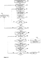
図3Aは、分散したMCUの呼びを作り出すプロセスを示す。分散したビデオ・カンファレンス・システム内で複数のエンド・ポイント(EP)をマルチ・サイト接続ユニット(MCU)に最適に設定することを自動的に生成し割り当てる方法は次のステップを含む。 FIG. 3A shows the process of creating a distributed MCU call. A method for automatically generating and allocating optimally setting a plurality of end points (EP) to a multi-site connection unit (MCU) within a distributed video conference system includes the following steps.
第1ステップ100は、重み付け関数に基づいて、利用可能なMCUのMCU優先リストを生成する。この重み付け関数は、MCUの好ましい特性およびプロパティとEPの数に基づいている。これは、MCU内の利用可能な処理資源の量とMCUをEPに接続するのに必要なバンド幅資源である。このリストから最良のMCUがマスターMCUとして選択される。
The
次のステップ110は、必要とされるMCUの数を予測することである。これは、現行のビデオ・カンファレンス・セッションの間に接続するのが必要なEPの数に基づいて行われる。ここから、ステップ120で十分なMCUがあるか否かがチェックされる。十分なMCUがない場合には、エラーメッセージがステップ140で表示され、分散したMCUの呼びを創設するプロセスは停止する。十分なMCUがある場合には、プロセスはいくつかのサブステップで継続する。
The
最初のサブステップ130は、ステップ100で生成された優先リストから必要とされるMCUを、選択されたMCUを含むデータベースの「選択」リストに追加する。
The
次のサブステップ160では、マスターMCUから、ステップ130で生成されたMCUデータベースのリスト内の他のMCUへの必要なリンクを計算する。
In the
この後、サブステップ170が行われる。ここでは、マスターMCUがビデオ・カンファレンス・リーダー(もしあれば)のEPに割り当てられる。このビデオ・カンファレンス・リーダーは、オーディオおよび/またはビデオ情報を他の全ての参加者に供給するEPである。 Thereafter, sub-step 170 is performed. Here, the master MCU is assigned to the EP of the video conference leader (if any). This video conference leader is an EP that supplies audio and / or video information to all other participants.
ステップ180において、ステップ130で生成された「選択」リスト内の次のMCUが処理される。最初は、これはマスターMCUであるが、次は、マスターMCUの後、第2の最良の重みを持つMCUである。
In
ステップ190において、各EPに対する呼びの重みの計算が実行される。ここで、EPとMCUとの間の呼びのコストは、重みの中に含まれるファクターの1つである。この後、ステップ200が行われ、ここで、各MCU用のEP優先リストが生成される。すなわち、各EPから「選択された」リスト内の別のMCUへの呼びの重みが、ステップ130で生成される。
In
ステップ210において、ステップ200で生成されたEP優先リスト内に残りのEPがあるかがチェックされる。ない場合には、EP優先リスト内の全てのエンド・ポイントが処理され、最適化ルーティンがステップ300で開始される。これが成功すると、現行ビデオ・カンファレンス内の全てのシステムが最適の方法で互いに接続される。この最適化ルーティンは、図3Bを参照して、以下詳述する。
In
EP優先リスト内に残りのEPがある場合には、新たなテストがステップ220で実行され、ステップ180に従って処理された現行MCUが満杯かチェックされる。満杯でない場合には、ステップ200で生成されたEP優先リストの最初のEPが現行MCUに割り当てられる。これは、ステップ230で実行され、その後、ステップ240が実行される。ここで、最初のEPがEP優先リストから外される。ステップ210、220、230、240を含むループが実行されるが、これは、全てのEPがMCUに割り当てられるまで、あるいは現行MCUが満杯になるまで、すなわちその資源が使い切るまで行われる。これが当てはまる場合には、ステップ250が実行される。
If there are remaining EPs in the EP priority list, a new test is performed at step 220 to check whether the current MCU processed according to step 180 is full. If not, the first EP in the EP priority list generated in
ステップ250において、ステップ130で生成された「選択」リストが空か否かのテストが行われる。空でない場合には、上記のステップ180に再び入り、その後ステップ190、200が実行される。「選択」リストが空の場合には、ステップ260で新たなMCUが利用可能かどうかのチェックが行われる。利用可能な場合、ステップ230で実行された全ての割り当てられたEPがステップ280で割り当てから外され(de-allocated)、プロセスが再び新たなMCUを選択リストに追加した(ステップ150)後、ステップ160から開始する。新たなMCUが利用可能でない場合には、エラーメッセージがステップ270で生成される。
In
前述したステップで実行されたEPとMCUの接続/割り当てを最適化することが望ましい。この理由は、あるケースでは、要求された資源は必要以上に遙かに多く、それ故に高価となるからである。 It is desirable to optimize the EP / MCU connection / allocation performed in the above steps. This is because in some cases, the required resources are much higher than necessary and are therefore expensive.
図3Bは、最終的に分散したMCUルートを最適化するプロセスを示す。最適化方法は、全てのEPがMCUに割り当てられた時、すなわちエラーメッセージが発生しなかった時に完了する。 FIG. 3B shows the process of optimizing the final distributed MCU route. The optimization method is completed when all EPs have been assigned to the MCU, i.e. no error message has occurred.
最適化方法は、ステップ400で開始し、これは、マスターMCUを除く全てのMCUからEPの割り当てを外すことにより行われる。割当除外リスト(de-allocated list)がステップ230で実行されたEPをMCUに割り当てる優先リストから生成される。
The optimization method starts at
ステップ410で、割当除外リストから次のEPが見いだされる。ステップ430で、割当除外リストから次のMCUが見いだされる。ステップ430で、EPとMCUとの間のルートが創設される。この後ステップ440で、このルートをルート群(collection of route)に追加する。
At
ステップ450で、割当除外MCUリストの終わりに到達したか否かがチェックされる。到達していない場合には、ステップ420に入り、ステップ420、430、440、450が実行されるが、これは、現行EPと割当除外リスト内のMCUとの間にルートが創設されるまで行われる。割当除外MCUリストの終了点に達すると、新たなテストがステップ460で実行される。このステップにおいては、EPリストの終了点に到達したか否かがチェックされる。到達していない場合には、MCUの割当除外リストは、ステップ470で、最初の場所にリセットされ、EPの割当除外リストから次ぎのEPが見いだされ、この後ステップ420−460が行われる。ステップ460が、EPリストの終了点に到達したと報告したときには、ステップ480に入る。
In
ステップ480において、ステップ400−460から得られたルート集団が最低のウエイトで分類される。
In
ステップ490において、分類したルート集団内のEPとMCUとの間の次のルートが見いだされる。ステップ500において、特定のMCUに十分な資源があるか否かがチェックされる。ない場合には、最適化プロセスは失敗し、ステップ300に入る前に示された元のソリューションが表示されて実行される。特定のMCUに十分な資源がある場合には、ステップ520に入る。
In
ステップ520において、ルート内に含まれるEPがMCUに割り当てられる。この後ステップ530が行われ、このルートが集団から取り除かれる。
In step 520, the EP included in the route is assigned to the MCU. This is followed by
ルートの集団内によりさらにルートは存在するか否かのチェックがステップ540で行われる。存在する場合には、ステップ490に再び入り、次のステップ500−530が全てのルートにアクセスされるまで実行される。
A check is made at
最適化プロセスは、ステップ550で終了する。
The optimization process ends at
上記の方法により、ビデオ・カンファレンス装置の間の呼びが効果的に安価な方法で設定され、中央集権化したロケーションを用いずに設定される。 With the above method, calls between video conferencing devices are set up in an effective and inexpensive way, without using a centralized location.
図3Aと3Bに関して記載した方法は、ベストモードであり、それ故に好ましいステップを含む。この方法の変更も可能であり、しかしそれも本発明の範囲内に入る。 The method described with respect to FIGS. 3A and 3B is the best mode and therefore includes preferred steps. Variations on this method are possible, but are within the scope of the invention.
本発明はまた、上記の方法に従った、分散したビデオ・カンファレンス・システム内の複数のEPをMCUへ最適な割り当てを自動的に行う装置に関する。 The invention also relates to an apparatus for automatically assigning optimally multiple EPs in a distributed video conference system to MCUs according to the method described above.
本発明の第2の目的は、ネットワーク内の複数のビデオ・カンファレンス装置を監視し管理する方法と装置を提供することである。ビデオ・カンファレンス装置は、ビデオ・カンファレンスの設定の際に含まれるあらゆる機器であり、例えば、内部MCUの有無を問わないエンド・ポイント、ゲートウェイ、ゲートキーパー、MCU等である。 It is a second object of the present invention to provide a method and apparatus for monitoring and managing a plurality of video conference devices in a network. The video conference device is any device included in setting up a video conference, and is, for example, an end point, a gateway, a gatekeeper, an MCU, or the like regardless of the presence or absence of an internal MCU.
監視(Monitoring)とは、呼びと参加者とそれらの状態に関する情報を見ることである。 Monitoring is the viewing of information about calls, participants and their status.
管理(Administration)とは、参加者の状態を変更すること、参加者を追加すること、参加者と外すこと等である。 Administration includes changing the state of a participant, adding a participant, removing a participant, and the like.
ビデオ・カンファレンスを監視し管理することは、ビデオ・カンファレンスに参加する装置の設定を成功裏に完了した後行われる。 Monitoring and managing the video conference is performed after successfully setting up the devices to participate in the video conference.
本発明の方法は、第1ステップとして、呼び中の装置からプロトコルと持続時間のような呼び情報を収集する。このステップは、各ビデオ・カンファレンス装置に対し、処理を促進するためにキャッシュに利用可能なさまざまな機能に対するサポート・レベルを行わせることにより実行する。このステップの後、管理機能を受信した後、マスター装置(通常、MCU,この方法におけるマスター装置は、カスケード接続された呼びマスターMCU(内部MCU)か、カスケード接続されていない呼びのMCU(外部MCU)か、ポイント間の呼びでは最大の機能を有するエンドポイントのいずれかである)が、特定のコマンド(無言(mute)、発言権(floor)、音量(volume))を実行できるかをチェックするステップが行われる。更にこの後、マスター装置が前記コマンドを実行できない場合には、スレーブ装置が、特定のコマンドを実行できるかをチェックするステップが続く。更にその後、マスター装置とスレーブ装置がこのコマンドを実行できない場合には、このコマンドが実行されることになるエンド・ポイント(EP)が、この特定のコマンドを実行できるかをチェックするステップが行われる。最終ステップとして、前記特定のコマンドを実行できる装置に対し、前記装置上でコマンドが実行される。 As a first step, the method of the present invention collects call information such as protocol and duration from the calling device. This step is performed by having each video conference device provide a level of support for the various functions available in the cache to facilitate processing. After this step, after receiving the management function, the master device (usually MCU, the master device in this method is either a cascaded call master MCU (internal MCU) or a non-cascaded call MCU (external MCU) ) Or one of the endpoints that has the most functionality in a call between points) checks whether a specific command (mute, floor, volume) can be executed Steps are performed. Further, if the master device cannot execute the command, this is followed by a step of checking whether the slave device can execute a specific command. Then, if the master device and slave device cannot execute this command, a step is performed to check whether the end point (EP) at which this command is executed can execute this particular command. . As a final step, a command is executed on the device for a device capable of executing the specific command.
監視し管理しているユーザー・インターフェースは、ビデオ・カンファレンス装置に動作可能に接続されている。すなわち、中央にあるサーバーからこれらのタスクを実行する必要はない。 A monitoring and managing user interface is operatively connected to the video conference device. That is, there is no need to perform these tasks from a central server.
次の3つの実施例においては、監視し管理する本発明の方法を用いた例が記載される。この場合、複数のシステムが接続され、呼びに係属するものとする。 In the next three examples, examples using the method of the present invention to monitor and manage are described. In this case, it is assumed that a plurality of systems are connected and are involved in the call.
さまざまな場合において、一人の管理者が、1つのインターフェースが全ての呼びを監視し管理することを望み、以下の説明は、これが本発明の方法により如何に行われるかを示す。 In various cases, a single administrator wants an interface to monitor and manage all calls, and the following description shows how this is done by the method of the present invention.
ケース:ポイント・トゥ・ポイント(Point-to-point)
監視:呼び情報は、ポイント・トゥ・ポイント(ポイント間)のカンファレンスにある複数のシステムの1つから集められる。この1つのシステムは、最大機能(MultiSite、ISDNバンド幅)を具備したシステムとして選択される。このシステムは、マスター・システムと称する。この情報は、プロトコル、会議継続時間等に関する情報を含む。この1つのシステムが、関連外(out-of-house)のシステムの場合には、関連(in-house)システムが、この情報を集めるのに用いられる。
Case: Point-to-point
Monitoring: Call information is collected from one of several systems in a point-to-point conference. This one system is selected as the system with maximum functionality (MultiSite, ISDN bandwidth). This system is referred to as the master system. This information includes information related to the protocol, conference duration, and the like. If this one system is an out-of-house system, an in-house system is used to collect this information.
管理:管理機能が、システムの能力に応じて、カンファレンス上で実行される時には、マスター・システムが最初にチェックされる。機能がそのマスター・システム上で実行できない場合には、他のシステムを用いてこの機能を実行する。この他のシステムが、関連システムでない場合には、この機能は実行不可能となる(どのようなシステムもこれに反して機能を実行することはできない)。通常、音量(volume)、無言(mute)が、それを制御しようとするエンド・ポイントで制御され、一方、会議の継続、参加者の追加と脱退、発言権制御(floor control)が、マスター・システムで行われる。 Management: When a management function is performed on a conference, depending on the capabilities of the system, the master system is checked first. If the function cannot be performed on that master system, perform the function using another system. If this other system is not a related system, this function cannot be executed (no system can execute the function on the contrary). Usually, volume and mute are controlled by the end point trying to control it, while continuation of the conference, adding and leaving participants, floor control is the master control. Done in the system.
ケース:MCU(内部または外部)
監視:呼び情報が、MCUであるMCUカンファレンス内のシステムから集められる。このシステムは、マスター・システムと称する。この情報は、プロトコル、継続時間等に関する情報を含む。
Case: MCU (internal or external)
Monitoring: Call information is collected from the system in the MCU conference that is the MCU. This system is referred to as the master system. This information includes information about the protocol, duration, etc.
管理:管理機能が、システムの能力に応じて、カンファレンス上で実行される時には、マスター・システムが最初にチェックされる。機能がそのマスター・システム上で実行できない場合には、その機能を実行することになるシステムがチェックされる(例、MCUが無言(mute)をサポートしない場合には、無言は無言状態におかれるべきサイトで実行される)。他のシステムが、関連システムでない場合には、この機能は実行不可能となる(どのようなシステムもこれに反して機能を実行することはできない)。通常、音量、無言(内部MCUにおいて)が、それを制御しようとする個々のエンド・ポイントで制御され、一方、会議の継続、参加者の追加と脱退、無言(外部MCUにおいて)、発言権制御が、マスター・システム(MCU、内部または外部のMCUのいずれか)で行われる。 Management: When a management function is performed on a conference, depending on the capabilities of the system, the master system is checked first. If the function cannot be performed on that master system, the system that will perform the function is checked (eg, if the MCU does not support mute, mute is left silent). Should be executed at the site). If the other system is not a related system, this function cannot be performed (no system can perform the function on the contrary). Normally, volume, mute (in the internal MCU) is controlled by the individual endpoints that want to control it, while conference continuation, adding and leaving participants, mute (in the external MCU), floor control Are performed on the master system (MCU, either internal or external MCU).
ケース:カスケード接続/分散MCU(内部または外部)
監視:呼び情報が、カンファレンス内でMCUとして機能する全てのシステムから集められる。あるシステムがカスケード接続/分散のトップにある場合には、このシステムが、マスター・システムと呼ばれる。この集められた情報は、プロトコルと会議継続時間等に関する情報を含む。
Case: Cascade / Distributed MCU (internal or external)
Monitoring: Call information is collected from all systems that function as MCUs in the conference. If a system is at the top of the cascade / distribution, this system is called the master system. This collected information includes information about the protocol, conference duration, etc.
管理:管理機能が、システムの能力に応じて、カンファレンス上で実行される時には、マスター・システム(マスターMCU)が最初にチェックされる。機能がそのマスター・システム上で実行できない場合には、他のMCUのおのおの(スレーブMCU)がチェックされる。このスレーブMCUがこの機能をサポートしない時は、この機能を実行することになるシステムがチェックされる(例、マスターMCUとスレーブMCUが無言(mute)をサポートしない場合には、無言は無言状態におかれるべきサイトで実行される)。他のシステムが、関連システムでない場合には、この機能は実行不可能となる(どのようなシステムもこれに反して機能を実行することはできない)。通常、音量、無言(内部MCUにおいて)が、それを制御しようとする個々のエンド・ポイントで制御され、一方、会議の継続、参加者の追加と脱退、無言(外部MCUにおいて)が、マスターMCUあるいはスレーブMCUで実行され、、発言権制御が、マスター・システム(MCU、内部または外部のMCUのいずれか)で行われる。 Management: When a management function is performed on a conference, depending on the capabilities of the system, the master system (master MCU) is checked first. If the function cannot be performed on that master system, each of the other MCUs (slave MCUs) is checked. When this slave MCU does not support this function, the system that will perform this function is checked (eg, if the master MCU and the slave MCU do not support mute, the mute will remain silent). Executed at the site to be placed). If the other system is not a related system, this function cannot be performed (no system can perform the function on the contrary). Normally, volume, mute (in the internal MCU) is controlled by the individual endpoints that want to control it, while conference continuation, participant addition and withdrawal, mute (in the external MCU) is the master MCU. Alternatively, it is executed by the slave MCU, and the floor control is performed by the master system (MCU, internal or external MCU).
本発明の方法と実際のシステム制御が如何に行われるかは、システム毎に異なる。TNADBERGシステムは、他の競業製品(RadVision、Polycom、Ezenia)等とは別の方法で管理機能をサポートしている。主要な点は、各システムは、さまざまな機能用にそのサポートレベルを利用可能にしている点である。呼び情報を集めるために、個々のシステムの状態が組み合わされる(最適化するために、多くの場合このような情報をマスター・システムに問い合わせるだけでよい)。しかし、管理を行うためには、本発明の方法/装置によれば、機能の実行は、最初にマスター・システムで、その後スレーブMCU(それらが用いられている場合には)で、最後に個々のシステムで試みる。 The method of the present invention and how the actual system control is performed varies from system to system. The TNADBRG system supports management functions in a manner different from other competitive products (RadVision, Polycom, Ezenia) and the like. The main point is that each system makes its support level available for various functions. In order to collect call information, the state of the individual systems is combined (in order to optimize, it is often only necessary to query the master system for such information). However, for management purposes, according to the method / apparatus of the present invention, the execution of the function is first in the master system, then in the slave MCU (if they are used) and finally in the individual. Try with the system.
その結果は、大部分の場合そして大部分の特徴でもって、マスター・システムのみにアクセスするだけでよく、その結果、IPネットワーク問題に起因する接続を失う機会が減ることになる。常時接続がマスター・システムでは可能となっているために、多くの機能にアクセスでき、そして、全てのシステムに接続する必要はない。 The result is that in most cases and with most features, only the master system needs to be accessed, thereby reducing the chance of losing connectivity due to IP network problems. Because permanent connection is possible in the master system, many functions can be accessed and it is not necessary to connect to all systems.
本発明の方法は、全てのカンファレンスを制御する1つのスクリーンと1つの方法を管理者に与え、それらは、ポイント・トゥ・ポイント、内部MCU、外部MCU、あるいは分散/カスケード接続したカンファレンスを問わない。これにより、同レベルの監視と管理機能を有するために、全ての呼びがそこを通らなければならない大きなMCUを必要としない。 The method of the present invention gives the administrator one screen and one way to control all conferences, whether point-to-point, internal MCU, external MCU, or distributed / cascaded conferences. . This eliminates the need for large MCUs that all calls must go through to have the same level of monitoring and management functions.
以上の説明は、本発明の一実施例に関するもので、この技術分野の当業者であれば、本発明の種々の変形例を考え得るが、それらはいずれも本発明の技術的範囲に包含される。特許請求の範囲の構成要素の後に記載した括弧内の番号は、図面の部品番号に対応し、発明の容易なる理解の為に付したものであり、発明を限定的に解釈するために用いてはならない。また、同一番号でも明細書と特許請求の範囲の部品名は必ずしも同一ではない。これは上記した理由による。 The above description relates to one embodiment of the present invention, and those skilled in the art can consider various modifications of the present invention, all of which are included in the technical scope of the present invention. The The numbers in parentheses described after the constituent elements of the claims correspond to the part numbers in the drawings, are attached for easy understanding of the invention, and are used for limiting the invention. Must not. In addition, the part numbers in the description and the claims are not necessarily the same even with the same number. This is for the reason described above.
図1
エンドポイント(内部MCUの有無を問わない)
図2
ダラス・システム、リサカー・システム、ニューヨーク・システム
図3A
100 ISDNバンド幅によりMCUを分類し、トップのMCU(マスター)を「選択 リスト」に追加する
110 必要とされるMCUを見積もる
120 MCUは十分か?
130 必要とされるMCUを「選択」リストに追加する
140 エラー
150 新たなMCUを「選択」リストに追加する
160 マスターからスレーブへのリンクを計算する
170 ビデオ・カンファレンス・リーダーをマスターMCUに追加する
180 「選択」リスト内の次のMCUを処理する
190 MCUからEPへの呼びのコストに基づいて、各エンドポイントに対する呼びの 重みを計算する
200 最低の呼びコスト重みによりEPリストを分類する
210 EPは残っているか?
220 MCUは満杯か?
230 EPリスト内の最初のエンドポイントを割り当てる
240 EPリストから最初のEPを取り除く
250 MCU「選択」リストは空か?
260 新たなMCUは利用可能か?
270 エラー
280 全てのエンドポイントの割り当てを外す、全てフリーにする
300 最適化(図3Bの400)
310 完了
図3B
400 マスターMCUを除く全のMCUからエンドポイントの割り当てを外す
410 割当除外リストから次のエンドポイントを得る
420 割当除外リストから次のMCUを得る
430 MCUとエンドポイントとの間のルートを創設する
440 ルートをルート集団に追加する
450 MCUリストの終わりか?
460 エンドポイントリストの終わりか?
470 MCUリストを最初の位置にリセットする
480 呼びの最低ウエイトによりルート集団を分類する
490 次のルートを得る
500 MCU上の資源は十分か?
510 出口 最適化が失敗し、元のソリューションを提示する
520 ルート内に含まれるエンドポイントをこのMCUに割り当てる
530 集団からルートを外す
540 更にルートがあるか?
550 完了
FIG.
Endpoint (with or without internal MCU)
FIG.
Dallas System, Lisa Car System, New York System Figure 3A
100 Classify MCUs by ISDN bandwidth and add top MCU (master) to “selection list” 110 Estimate required
130 Add required MCU to “Select”
Is 220 MCU full?
230 Assign the first endpoint in the
260 Is a new MCU available?
270
310 Completion Figure 3B
400 Unassign endpoint from all MCUs except
460 End of endpoint list?
470 Reset MCU list to
510 Exit Optimization fails and presents the original solution 520 Assigns endpoints contained within this route to this
550 complete
Claims (17)
(a) 必要とされるマルチサイト接続ユニットの数を、ビデオ・カンファレンス・セッションでの接続に必要とされるエンド・ポイントの数に基づいて、見積るステップと、
(b) 前記各エンド・ポイントをマルチサイト接続ユニットに割り当てる前記見積もりにより利用可能な十分の数のマルチサイト接続ユニットがあるかをチェックし、優先リストを生成するステップと、
前記優先リストとは、前記マルチサイト接続ユニットに優先して割り当てられるエンド・ポイントのリストであり、
(c) 前記エンド・ポイントをマルチサイト接続ユニットに接続することにより、前記エンド・ポイントをマルチサイト接続ユニットへ割り当てるステップと
を有し、
前記ステップ(c)は、重み付け関数に従って行われ、さらに、以下のステップを有する、
前記重み付け関数は、前記マルチサイト接続ユニット内の利用可能な処理資源の量と、前記マルチサイト接続ユニットをエンド・ポイントに接続するのに必要なバンド幅資源の関数であり、
(c1) 前記マルチサイト接続ユニットに割り当てられるエンド・ポイントの前記優先リストから、マスタ・マルチサイト接続ユニット以外の全てのマルチサイト接続ユニットからエンド・ポイントの割当を除外する割当除外リストを生成するステップと、
前記割当除外リストは、エンド・ポイントを前記マスタ・マルチサイト接続ユニット以外の全てのマルチサイト接続ユニットへの割り当てを除外するリストであり、
(c2) 前記マルチサイト接続ユニットの割当除外リスト内の各マルチサイト接続ユニットと各エンド・ポイントの間のルートを生成するステップと、
(c3) これらのルートを、ルート群を有するリストに追加するステップと、
(c4) 前記ルート群を有するリストを、最小重みの呼びにより、分類するステップと、
(c5) 十分な資源がマルチサイト接続ユニット上で利用可能な場合には、ルート群内に含まれる各エンド・ポイントを、前記重み付け関数により好ましいとされたマルチサイト接続ユニットに割り当て、
(c6) 前記エンド・ポイントが存在する前記(c4)ステップで分類されたリスト中の他の全てのルートを除くステップと
を有する
ことを特徴とする分散したテレビ会議システムにおいて、複数のエンドポイントのマルチサイト接続ユニットへの最適設定の生成と割り当てを自動的に行う方法。In a distributed video conferencing system, where multiple end points are automatically generated and assigned optimal settings to multisite connection units,
(A) estimating the number of multi-site connection units required based on the number of endpoints required for connection in a video conference session;
(B) checking whether there is a sufficient number of multi-site connection units available by the estimate assigning each end point to a multi-site connection unit, and generating a priority list;
The priority list is a list of end points assigned in preference to the multi-site connection unit;
(C) connecting the end point to a multi-site connection unit by connecting the end point to a multi-site connection unit;
The step (c) is performed according to a weighting function, and further includes the following steps:
The weighting function is a function of the amount of processing resources available in the multi-site connection unit and the bandwidth resources required to connect the multi-site connection unit to an end point;
(C1) Generating an assignment exclusion list for excluding assignment of end points from all multisite connection units other than the master multisite connection unit from the priority list of end points assigned to the multisite connection unit When,
The allocation exclusion list is a list that excludes allocation of end points to all multisite connection units other than the master multisite connection unit;
(C2) generating a route between each multi-site connection unit in the multi-site connection unit allocation exclusion list and each end point;
(C3) adding these routes to a list having routes;
(C4) classifying the list having the route group by calling a minimum weight;
(C5) If sufficient resources are available on the multi-site connection unit, assign each end point included in the route group to the multi-site connection unit determined as preferred by the weighting function;
(C6) A step of removing all other routes in the list classified in the step (c4) in which the end point exists. A method of automatically generating and assigning optimal settings to multi-site connection units.
(a1) 重み付け関数に基づいて利用可能なマルチサイト接続ユニット優先リストを、マルチサイト接続ユニットの好ましい特性あるいはプロパティおよびエンド・ポイントの数に基づいて、生成するステップと、
(a2) 最も重いマルチサイト接続ユニットを、マスタ・マルチサイト接続ユニットとして選択するステップと
を有する
ことを特徴とする請求項1記載の方法。The step (a)
(A1) generating a multi-site connection unit priority list that is available based on a weighting function based on the preferred characteristics or properties of the multi-site connection unit and the number of end points;
And (a2) selecting the heaviest multisite connection unit as a master multisite connection unit.
ことを特徴とする請求項2記載の方法。3. The method of claim 2, wherein the generated multi-site connection unit priority list is classified according to location, bandwidth, and channel at a scheduled meeting.
ことを特徴とする請求項1記載の方法。If the multisite connection unit in question does not have sufficient resources, the assignment of the endpoints contained in the route group to that multisite connection unit is stopped and assigned before step (c). The method of claim 1, wherein the selected route is selected.
(b1) 前記マスタ・マルチサイト接続ユニットから、前記マルチサイト接続ユニット優先リスト内の他のマルチサイト接続ユニットへの必要なリンクを計算するステップと、
(b2) 前記マスタ・マルチサイト接続ユニットを、ビデオ・カンファレンス・リーダーのエンド・ポイントに割り当てるステップと、
(b3) 各エンド・ポイントに対する呼びの重みを計算するステップと、
前記エンド・ポイントとマルチサイト接続ユニットとの間の呼びのコストは、前記重み内に含まれる係数であり、
(b4) 各マルチサイト接続ユニットに対し、エンド・ポイント優先リストを生成するステップと、
(b5) 前記エンド・ポイントとマルチサイト接続ユニットに対し生成された優先リストに従って、各エンド・ポイントをマルチサイト接続ユニットに割り当てるステップと
を有する
ことを特徴とする請求項1記載の方法。The step (b)
(B1) calculating a necessary link from the master multisite connection unit to another multisite connection unit in the multisite connection unit priority list;
(B2) assigning said master multi-site connection unit to a video conference leader end point;
(B3) calculating a call weight for each end point;
The cost of the call between the end point and the multi-site connection unit is a factor included in the weight,
(B4) generating an end point priority list for each multi-site connection unit;
The method of claim 1, further comprising the step of: (b5) assigning each end point to a multi-site connection unit according to a priority list generated for said end point and multi-site connection unit.
ことを特徴とする請求項5記載の方法。6. The method of claim 5, wherein the call weight calculation includes a bandwidth factor.
前記重み付けファクターは、コストとバンド幅を含む
ことを特徴とする請求項5記載の方法。The generated endpoint preference list is categorized by a weighting factor,
6. The method of claim 5, wherein the weighting factor includes cost and bandwidth.
ことを特徴とする請求項7記載の方法。The method of claim 7, wherein the generated end point assignment priority list is classified by one of the weighting factors.
ことを特徴とする請求項7記載の方法。The method of claim 7, wherein the generated end point assignment priority list is classified according to the weighting factor.
ことを特徴とする請求項5記載の方法。6. The method of claim 5, wherein the assignment of each end point to a multi-site connection unit is performed according to a sorted list of available multi-site connection units.
ことを特徴とする請求項5記載の方法。6. The method of claim 5, wherein the assignment of each end point to a multi-site connection unit is performed until all end points are assigned to the multi-site connection unit.
ことを特徴とする請求項5記載の方法。Each of the assigned end points is assigned one or more end points due to lack of resources on the multi-site connection unit in the end point assignment priority list, 6. The method of claim 5, wherein the method is deassigned.
ことを特徴とする請求項12記載の方法。13. The method of claim 12, wherein the unassigned end point is reassigned after adding a new multisite connection unit to the multisite connection unit assignment priority list.
ことを特徴とする請求項5記載の方法。6. The method of claim 5, wherein the end point is assigned to the next multi-site connection unit when the previous multi-site connection unit is occupied on the priority list.
(a) 必要とされるマルチサイト接続ユニットの数を、ビデオ・カンファレンス・セッションでの接続に必要とされるエンド・ポイントの数に基づいて見積るよう構成された、見積もりユニットと、
(b) 各エンド・ポイントをマルチサイト接続ユニットに割り当てることにより、見積もりにより必要とされる十分の数のマルチサイト接続ユニットがあるかをチェックし、優先リストを生成するよう構成された、チェック・ユニットと、
前記優先リストとは、前記マルチサイト接続ユニットに優先して割り当てられるエンド・ポイントのリストであり、
(c) エンド・ポイントをマルチサイト接続ユニットに接続することにより、エンド・ポイントのマルチサイト接続ユニットの割り当てを行うよう構成された、割り当てユニットと
を有し、
前記割り当てユニット(c)は、重み付け関数に従って動作し、
前記重み付け関数は、前記マルチサイト接続ユニット内の利用可能な処理資源の量と、前記マルチサイト接続ユニットをエンド・ポイントに接続するのに必要なバンド幅資源の関数であり、
さらに、
(c1) エンド・ポイントをマルチサイト接続ユニットに割り当てる割当優先リストから、マスタ・マルチサイト接続ユニット以外の全てのマルチサイト接続ユニットからのエンド・ポイントの割当除外リストを生成する手段と、
前記割当除外リストは、エンド・ポイントを前記マスタ・マルチサイト接続ユニット以外の全てのマルチサイト接続ユニットへの割り当てを除外するリスト
(c2) マルチサイト接続ユニットの割当除外リスト内の各マルチサイト接続ユニットと各エンド・ポイントとの間のルートを生成する手段と、
(c3) これらのルートをルート群を具備したリストに追加する手段と、
(c4) ルート群を具備したリストを最小重みの呼びにより分類する手段と、
(c5) 十分な資源の利用可能性に応じ、ルート群に含まれる各エンド・ポイントを、前記重み付け関数により好ましいとされたマルチサイト接続ユニットに割り当てる手段と、
(c6) 前記エンド・ポイントが存在する分類リスト内の他の資源を取り除く手段と
を有する
ことを特徴とする分散したビデオ・カンファレンス・システムにおいて、複数のエンド・ポイントのマルチサイト接続ユニットへの最適設定の生成と割り当てを自動的に行う装置。In a distributed video conference system, in a device that automatically generates and assigns optimal settings to a multi site connection unit of multiple end points,
(A) an estimation unit configured to estimate the number of multi-site connection units required based on the number of endpoints required for connection in a video conference session;
(B) Check that there is a sufficient number of multi-site connectivity units required by the estimate by assigning each end point to a multi-site connectivity unit and generate a priority list. Unit,
The priority list is a list of end points assigned in preference to the multi-site connection unit;
(C) having an allocation unit configured to allocate the multi-site connection unit of the end point by connecting the end point to the multi-site connection unit;
The allocation unit (c) operates according to a weighting function;
The weighting function is a function of the amount of processing resources available in the multi-site connection unit and the bandwidth resources required to connect the multi-site connection unit to an end point;
further,
(C1) means for generating an end point assignment exclusion list from all multisite connection units other than the master multisite connection unit from an assignment priority list for assigning end points to the multisite connection unit;
The allocation exclusion list is a list for excluding allocation of end points to all multisite connection units other than the master multisite connection unit. (C2) Each multisite connection unit in the allocation exclusion list of multisite connection units And a means for generating a route between each end point;
(C3) means for adding these routes to a list comprising routes,
(C4) means for classifying the list having the route group by calling with the minimum weight;
(C5) means for allocating each end point included in the route group to a multi-site connection unit determined by the weighting function according to availability of sufficient resources;
(C6) Optimizing a multi-site connection unit of a plurality of end points in a distributed video conference system, characterized in that it has means for removing other resources in the classification list in which the end points exist A device that automatically generates and assigns settings.
(a1) 重み付け関数に基づいた利用可能なマルチサイト接続ユニット割当優先リストを、マルチサイト接続ユニットの好ましい特性あるいはプロパティおよびエンド・ポイントの数に基づいて、生成する手段と、
(a2) 最良の重みを有するマルチサイト接続ユニットをマスタ・マルチサイト接続ユニットとして選択する手段と
を有する
ことを特徴とする請求項15記載の装置。The estimation unit (a) is
(A1) means for generating an available multisite connection unit allocation priority list based on a weighting function based on preferred characteristics or properties of the multisite connection unit and the number of end points;
16. The apparatus of claim 15, further comprising: (a2) means for selecting a multisite connection unit having the best weight as a master multisite connection unit.
(b1) マスタ・マルチサイト接続ユニットから、マルチサイト接続ユニット優先リスト内の他のマルチサイト接続ユニットへの必要なリンクを計算する手段と、
(b2) 前記マスタ・マルチサイト接続ユニットをビデオ・カンファレンス・リーダーのエンド・ポイントに割り当てる手段と、
(b3) 各エンド・ポイントに対する呼びの重みを計算する手段と、
前記エンド・ポイントとマルチサイト接続ユニットとの間の呼びのコストは、重みに含まれる係数であり、
(b4) 各マルチサイト接続ユニットに対し、エンド・ポイント優先リストを生成する手段と、
(b5) エンド・ポイントとマルチサイト接続ユニットに対し生成された前記優先リストに従って、各エンド・ポイントをマルチサイト接続ユニットに割り当てる手段と
を有する
ことを特徴とする請求項15記載の装置。The check unit (b)
(B1) means for calculating the necessary links from the master multisite connection unit to other multisite connection units in the multisite connection unit priority list;
(B2) means for assigning said master multi-site connection unit to a video conference leader end point;
(B3) means for calculating a call weight for each end point;
The cost of the call between the end point and the multi-site connection unit is a factor included in the weight,
(B4) means for generating an endpoint priority list for each multi-site connection unit;
16. The apparatus of claim 15, further comprising: (b5) means for assigning each end point to a multisite connection unit according to the priority list generated for the end point and the multisite connection unit.
Applications Claiming Priority (2)
| Application Number | Priority Date | Filing Date | Title |
|---|---|---|---|
| NO20033106A NO318974B1 (en) | 2003-07-07 | 2003-07-07 | Distributed MCU |
| PCT/NO2004/000155 WO2005004481A1 (en) | 2003-07-07 | 2004-05-28 | Distributed mcu |
Publications (2)
| Publication Number | Publication Date |
|---|---|
| JP2007521753A JP2007521753A (en) | 2007-08-02 |
| JP4378651B2 true JP4378651B2 (en) | 2009-12-09 |
Family
ID=27800784
Family Applications (1)
| Application Number | Title | Priority Date | Filing Date |
|---|---|---|---|
| JP2006518565A Expired - Fee Related JP4378651B2 (en) | 2003-07-07 | 2004-05-28 | Distributed MCU (multipoint control unit) |
Country Status (9)
| Country | Link |
|---|---|
| US (1) | US7456858B2 (en) |
| EP (2) | EP1895776B1 (en) |
| JP (1) | JP4378651B2 (en) |
| CN (1) | CN100499792C (en) |
| AT (1) | ATE381210T1 (en) |
| DE (1) | DE602004010676T2 (en) |
| ES (1) | ES2298758T3 (en) |
| NO (1) | NO318974B1 (en) |
| WO (1) | WO2005004481A1 (en) |
Cited By (2)
| Publication number | Priority date | Publication date | Assignee | Title |
|---|---|---|---|---|
| EP3029933A1 (en) | 2014-11-26 | 2016-06-08 | Ricoh Company, Ltd. | Apparatus, system, and method of controlling session, and carrier means |
| US9906570B2 (en) | 2014-09-19 | 2018-02-27 | Ricoh Company, Ltd. | Session control system, communication terminal, communication system, session control method, and medium |
Families Citing this family (66)
| Publication number | Priority date | Publication date | Assignee | Title |
|---|---|---|---|---|
| CN100359942C (en) * | 2003-11-05 | 2008-01-02 | 华为技术有限公司 | Visual conference system and its managing method |
| US7492730B2 (en) * | 2005-04-19 | 2009-02-17 | Polycom, Inc. | Multi-site conferencing system and method |
| US7817180B2 (en) * | 2005-04-28 | 2010-10-19 | Apple Inc. | Video processing in a multi-participant video conference |
| US9486408B2 (en) * | 2005-12-01 | 2016-11-08 | University Of Massachusetts Lowell | Botulinum nanoemulsions |
| US20070133438A1 (en) * | 2005-12-14 | 2007-06-14 | Cisco Technology, Inc. | Method and system for reserving resources in a conferencing system |
| US7800642B2 (en) | 2006-03-01 | 2010-09-21 | Polycom, Inc. | Method and system for providing continuous presence video in a cascading conference |
| US8699384B2 (en) * | 2006-03-15 | 2014-04-15 | American Teleconferencing Services, Ltd. | VOIP conferencing |
| US7581038B1 (en) | 2006-03-16 | 2009-08-25 | Polycom, Inc. | Multicast distribution over one or more addressable buses wherein a switch includes a remapping table for inputting address for one or more destinations |
| CN101047828B (en) * | 2006-03-31 | 2011-05-25 | 联想(北京)有限公司 | Distribution conference system |
| US7675537B2 (en) * | 2006-03-31 | 2010-03-09 | Polycom, Inc. | System, method, and apparatus for extending wireless personal area networks using conferencing connection |
| CN100438613C (en) * | 2006-04-05 | 2008-11-26 | 北京华纬讯电信技术有限公司 | Transmission method of audio/video digital codes stream in multimedia video meeting's system |
| US8705558B2 (en) * | 2006-06-01 | 2014-04-22 | Cisco Technology, Inc. | Swapping bandwidth reservations |
| US7937442B2 (en) * | 2006-09-22 | 2011-05-03 | Microsoft Corporation | Multipoint control unit (MCU) failure detection and rollover |
| US8150917B2 (en) * | 2006-09-22 | 2012-04-03 | Microsoft Corporation | High availability conferencing |
| CN101179692B (en) * | 2006-11-08 | 2011-03-02 | 中兴通讯股份有限公司 | Video signal conference system MCU resource scheduling method |
| JP2008147877A (en) * | 2006-12-07 | 2008-06-26 | Toshiba Corp | Conference system |
| EP2151122B1 (en) * | 2007-02-14 | 2014-01-22 | Teliris, Inc. | Telepresence conference room layout, dynamic scenario manager, diagnostics and control system and method |
| US8208004B2 (en) * | 2007-05-08 | 2012-06-26 | Radvision Ltd. | Device, methods, and media for providing multi-point video conferencing unit functions |
| US7921244B2 (en) * | 2007-07-04 | 2011-04-05 | Ours Technology, Inc. | Data sharing and transfer systems and methods |
| EP2201762B1 (en) * | 2007-10-12 | 2020-03-18 | Polycom, Inc. | Configuring videoconferencing systems to create video sessions with realistic presence |
| US9602295B1 (en) * | 2007-11-09 | 2017-03-21 | Avaya Inc. | Audio conferencing server for the internet |
| TW200926833A (en) * | 2007-12-03 | 2009-06-16 | Nat Applied Res Lab Nat Ct For High Performance Computing | Display system and display method capable of receiving multiple sources and with synchronous multiple outputs |
| US8319820B2 (en) * | 2008-06-23 | 2012-11-27 | Radvision, Ltd. | Systems, methods, and media for providing cascaded multi-point video conferencing units |
| US8355040B2 (en) * | 2008-10-16 | 2013-01-15 | Teliris, Inc. | Telepresence conference room layout, dynamic scenario manager, diagnostics and control system and method |
| CN101515948B (en) * | 2009-03-31 | 2012-04-25 | 华为终端有限公司 | Management method, management device and management system in distributed multi-point conference system |
| CN101557497B (en) * | 2009-05-22 | 2011-12-28 | 华为终端有限公司 | Conference auditing method and terminal and system thereof |
| US8437282B2 (en) | 2009-06-21 | 2013-05-07 | Clearone Communications Hong Kong Limited | System and method of multi-endpoint data conferencing |
| US8319816B1 (en) * | 2009-07-28 | 2012-11-27 | Insors Integrated Communications | Methods, systems and program products for efficient communication of data between conference servers |
| CN101674451B (en) * | 2009-09-27 | 2012-05-09 | 中兴通讯股份有限公司 | Method, system, central control subsystem and video terminal for controlling multipoint videoconference |
| JP5999873B2 (en) * | 2010-02-24 | 2016-09-28 | 株式会社リコー | Transmission system, transmission method, and program |
| CN101848099B (en) * | 2010-03-19 | 2012-12-05 | 西安电子科技大学 | Network conference system and conference realization method thereof |
| US9143729B2 (en) * | 2010-05-12 | 2015-09-22 | Blue Jeans Networks, Inc. | Systems and methods for real-time virtual-reality immersive multimedia communications |
| CN101931782B (en) * | 2010-08-25 | 2015-08-12 | 中兴通讯股份有限公司 | For flow processing method and the device of multipoint control unit |
| US8744065B2 (en) | 2010-09-22 | 2014-06-03 | Avaya Inc. | Method and system for monitoring contact center transactions |
| US9736312B2 (en) | 2010-11-17 | 2017-08-15 | Avaya Inc. | Method and system for controlling audio signals in multiple concurrent conference calls |
| CN102571526B (en) * | 2010-12-08 | 2015-05-06 | 华为终端有限公司 | Regulating method of conference site bandwidth, device, conference terminal and media control server |
| CN102025971A (en) * | 2010-12-15 | 2011-04-20 | 广东威创视讯科技股份有限公司 | Dynamic distribution method of video session media server resources |
| CN102427518B (en) * | 2010-12-29 | 2013-07-10 | 南京联坤软件技术有限公司 | On-demand networking video conference system |
| US8866873B2 (en) * | 2011-10-08 | 2014-10-21 | Mitel Networks Corporation | System for distributing video conference resources among connected parties and methods thereof |
| US8611877B2 (en) | 2011-10-31 | 2013-12-17 | Blackberry Limited | Automatic management control of external resources |
| EP2587778B1 (en) * | 2011-10-31 | 2017-07-19 | BlackBerry Limited | Automatic management control of external resources |
| US9020119B2 (en) | 2011-10-31 | 2015-04-28 | Blackberry Limited | Moderation control method for participants in a heterogeneous conference call |
| EP2774321A4 (en) * | 2011-11-01 | 2015-07-15 | Teliris Inc | Cloud-based interoperability platform for video conferencing |
| US20130215215A1 (en) * | 2011-11-01 | 2013-08-22 | Teliris, Inc. | Cloud-based interoperability platform using a software-defined networking architecture |
| CN102364935B (en) * | 2011-11-18 | 2013-06-05 | 苏州阔地网络科技有限公司 | Audio and video transmission method of network conference and system thereof |
| GB2520451B (en) | 2012-03-20 | 2015-09-30 | Media Network Services As | Data distribution system |
| US9065873B2 (en) | 2012-10-18 | 2015-06-23 | Cisco Technology, Inc. | Reduction of chaining in conference sessions |
| US9215414B2 (en) * | 2013-03-15 | 2015-12-15 | Cisco Technology, Inc. | Selection of a Multipoint Control Unit (MCU) for a video meeting on a network |
| CN104065682B (en) * | 2013-03-21 | 2017-10-10 | 赛恩倍吉科技顾问(深圳)有限公司 | Data transmission method |
| CN103237026B (en) * | 2013-04-22 | 2016-09-14 | 张志涵 | The system and method that additional information is mutual are triggered with calling |
| KR20140140946A (en) * | 2013-05-30 | 2014-12-10 | 한국전자통신연구원 | Multipoint control unit and method for provinding service thereof |
| WO2014194319A1 (en) * | 2013-05-31 | 2014-12-04 | Vidyo, Inc. | Systems and methods for room system pairing in video conferencing |
| US9118654B2 (en) | 2013-10-11 | 2015-08-25 | Edifire LLC | Methods and systems for compliance monitoring in secure media-based conferencing |
| US9118809B2 (en) | 2013-10-11 | 2015-08-25 | Edifire LLC | Methods and systems for multi-factor authentication in secure media-based conferencing |
| WO2015105408A1 (en) | 2014-01-08 | 2015-07-16 | Wafina Sdn. Bhd. | Self-learning and intelligent system for continually improving quality and performance of multimedia conference |
| WO2015117277A1 (en) * | 2014-02-10 | 2015-08-13 | 华为技术有限公司 | Method, apparatus and system for controlling multiparty real-time communication |
| CN103997617A (en) * | 2014-02-17 | 2014-08-20 | 宁波公众信息产业有限公司 | Control device and method of video scheduling |
| CN104980685B (en) * | 2014-04-14 | 2018-09-14 | 纬创资通股份有限公司 | Video service providing method and Video service provide system |
| US10485855B2 (en) * | 2014-05-01 | 2019-11-26 | Anterios, Inc. | Demonstrable efficacy across or within patient populations |
| US9131112B1 (en) | 2014-09-29 | 2015-09-08 | Edifire LLC | Dynamic signaling and resource allocation in secure media-based conferencing |
| US9282130B1 (en) | 2014-09-29 | 2016-03-08 | Edifire LLC | Dynamic media negotiation in secure media-based conferencing |
| US9167098B1 (en) * | 2014-09-29 | 2015-10-20 | Edifire LLC | Dynamic conference session re-routing in secure media-based conferencing |
| US9137187B1 (en) | 2014-09-29 | 2015-09-15 | Edifire LLC | Dynamic conference session state management in secure media-based conferencing |
| CN106714000A (en) * | 2015-07-14 | 2017-05-24 | 三亚中兴软件有限责任公司 | Control method, system and device of conference terminal authority |
| CN107306315B (en) * | 2016-04-18 | 2020-09-29 | 华为技术有限公司 | Voice conference creating method, conference server and system |
| CN106851036B (en) * | 2017-01-20 | 2019-08-30 | 广州广哈通信股份有限公司 | A kind of conllinear voice conferencing dispersion mixer system |
Family Cites Families (10)
| Publication number | Priority date | Publication date | Assignee | Title |
|---|---|---|---|---|
| JP3181167B2 (en) * | 1994-03-18 | 2001-07-03 | 富士通株式会社 | Connection / disconnection method in cascade configuration of multipoint conference system |
| US5473363A (en) * | 1994-07-26 | 1995-12-05 | Motorola, Inc. | System, method and multipoint control unit for multipoint multimedia conferencing |
| US5594725A (en) * | 1995-12-28 | 1997-01-14 | Vtel Corporation | Process and system for video rate control in a multipoint video conference |
| US6157401A (en) | 1998-07-17 | 2000-12-05 | Ezenia! Inc. | End-point-initiated multipoint videoconferencing |
| US6414707B1 (en) | 1998-10-16 | 2002-07-02 | At&T Corp. | Apparatus and method for incorporating virtual video conferencing environments |
| CA2776323C (en) | 1999-11-08 | 2015-05-19 | Polycom Israel Ltd | A system and method for controlling one or more multipoint control units as one multipoint control unit |
| US7206016B2 (en) * | 2000-05-01 | 2007-04-17 | Polycom, Inc. | Filtering artifacts from multi-threaded video |
| US20020064136A1 (en) * | 2000-11-02 | 2002-05-30 | O'neil Timothy M. | Conferencing network resource optimization for multi-point conferences |
| CN1134936C (en) * | 2001-02-06 | 2004-01-14 | 华为技术有限公司 | Method for implementing video communication service and its information data format |
| US6590603B2 (en) * | 2001-10-31 | 2003-07-08 | Forgent Networks, Inc. | System and method for managing streaming data |
-
2003
- 2003-07-07 NO NO20033106A patent/NO318974B1/en not_active IP Right Cessation
-
2004
- 2004-05-28 EP EP07253632.9A patent/EP1895776B1/en not_active Not-in-force
- 2004-05-28 US US10/856,472 patent/US7456858B2/en active Active
- 2004-05-28 CN CNB2004800196191A patent/CN100499792C/en not_active Expired - Fee Related
- 2004-05-28 JP JP2006518565A patent/JP4378651B2/en not_active Expired - Fee Related
- 2004-05-28 EP EP04735422A patent/EP1654873B1/en not_active Not-in-force
- 2004-05-28 ES ES04735422T patent/ES2298758T3/en active Active
- 2004-05-28 WO PCT/NO2004/000155 patent/WO2005004481A1/en active IP Right Grant
- 2004-05-28 AT AT04735422T patent/ATE381210T1/en not_active IP Right Cessation
- 2004-05-28 DE DE602004010676T patent/DE602004010676T2/en active Active
Cited By (2)
| Publication number | Priority date | Publication date | Assignee | Title |
|---|---|---|---|---|
| US9906570B2 (en) | 2014-09-19 | 2018-02-27 | Ricoh Company, Ltd. | Session control system, communication terminal, communication system, session control method, and medium |
| EP3029933A1 (en) | 2014-11-26 | 2016-06-08 | Ricoh Company, Ltd. | Apparatus, system, and method of controlling session, and carrier means |
Also Published As
| Publication number | Publication date |
|---|---|
| NO318974B1 (en) | 2005-05-30 |
| US20050007446A1 (en) | 2005-01-13 |
| JP2007521753A (en) | 2007-08-02 |
| EP1895776B1 (en) | 2015-07-08 |
| ES2298758T3 (en) | 2008-05-16 |
| ATE381210T1 (en) | 2007-12-15 |
| DE602004010676T2 (en) | 2009-01-02 |
| WO2005004481A1 (en) | 2005-01-13 |
| EP1895776A3 (en) | 2008-03-19 |
| EP1654873B1 (en) | 2007-12-12 |
| NO20033106D0 (en) | 2003-07-07 |
| EP1654873A1 (en) | 2006-05-10 |
| CN100499792C (en) | 2009-06-10 |
| US7456858B2 (en) | 2008-11-25 |
| DE602004010676D1 (en) | 2008-01-24 |
| CN1820505A (en) | 2006-08-16 |
| EP1895776A2 (en) | 2008-03-05 |
Similar Documents
| Publication | Publication Date | Title |
|---|---|---|
| JP4378651B2 (en) | Distributed MCU (multipoint control unit) | |
| US7830824B2 (en) | System and method for providing reservationless third party meeting rooms | |
| CA2776323C (en) | A system and method for controlling one or more multipoint control units as one multipoint control unit | |
| US10079714B2 (en) | Conference call resource assignment for failover | |
| US7174365B1 (en) | System and method for controlling one or more multipoint control units as one multipoint control unit | |
| US7085243B2 (en) | System and method for providing reservationless conferencing | |
| CN1810029B (en) | Method for setup of meetings and conferences | |
| CN100359942C (en) | Visual conference system and its managing method | |
| US7975073B2 (en) | Middleware server for interfacing communications, multimedia, and management systems | |
| JP2007534266A (en) | System and method for including participants in a conference call | |
| US20110069642A1 (en) | Method and apparatus for dynamically allocating resources for large-scale multimedia conferences | |
| US20050025074A1 (en) | Automatic call routing | |
| WO2015105408A1 (en) | Self-learning and intelligent system for continually improving quality and performance of multimedia conference | |
| US7076684B2 (en) | System and method for re-routing failed video calls | |
| JP2004064394A (en) | Television communication system | |
| CN117834801A (en) | Inter-region cascade bandwidth allocation method and system thereof |
Legal Events
| Date | Code | Title | Description |
|---|---|---|---|
| A131 | Notification of reasons for refusal |
Free format text: JAPANESE INTERMEDIATE CODE: A131 Effective date: 20090225 |
|
| A601 | Written request for extension of time |
Free format text: JAPANESE INTERMEDIATE CODE: A601 Effective date: 20090521 |
|
| A602 | Written permission of extension of time |
Free format text: JAPANESE INTERMEDIATE CODE: A602 Effective date: 20090528 |
|
| A601 | Written request for extension of time |
Free format text: JAPANESE INTERMEDIATE CODE: A601 Effective date: 20090624 |
|
| A602 | Written permission of extension of time |
Free format text: JAPANESE INTERMEDIATE CODE: A602 Effective date: 20090701 |
|
| A521 | Request for written amendment filed |
Free format text: JAPANESE INTERMEDIATE CODE: A523 Effective date: 20090715 |
|
| A131 | Notification of reasons for refusal |
Free format text: JAPANESE INTERMEDIATE CODE: A131 Effective date: 20090812 |
|
| A521 | Request for written amendment filed |
Free format text: JAPANESE INTERMEDIATE CODE: A523 Effective date: 20090812 |
|
| TRDD | Decision of grant or rejection written | ||
| A01 | Written decision to grant a patent or to grant a registration (utility model) |
Free format text: JAPANESE INTERMEDIATE CODE: A01 Effective date: 20090902 |
|
| A01 | Written decision to grant a patent or to grant a registration (utility model) |
Free format text: JAPANESE INTERMEDIATE CODE: A01 |
|
| A61 | First payment of annual fees (during grant procedure) |
Free format text: JAPANESE INTERMEDIATE CODE: A61 Effective date: 20090902 |
|
| FPAY | Renewal fee payment (event date is renewal date of database) |
Free format text: PAYMENT UNTIL: 20121002 Year of fee payment: 3 |
|
| R150 | Certificate of patent or registration of utility model |
Ref document number: 4378651 Country of ref document: JP Free format text: JAPANESE INTERMEDIATE CODE: R150 Free format text: JAPANESE INTERMEDIATE CODE: R150 |
|
| FPAY | Renewal fee payment (event date is renewal date of database) |
Free format text: PAYMENT UNTIL: 20121002 Year of fee payment: 3 |
|
| S111 | Request for change of ownership or part of ownership |
Free format text: JAPANESE INTERMEDIATE CODE: R313113 |
|
| FPAY | Renewal fee payment (event date is renewal date of database) |
Free format text: PAYMENT UNTIL: 20121002 Year of fee payment: 3 |
|
| R350 | Written notification of registration of transfer |
Free format text: JAPANESE INTERMEDIATE CODE: R350 |
|
| FPAY | Renewal fee payment (event date is renewal date of database) |
Free format text: PAYMENT UNTIL: 20131002 Year of fee payment: 4 |
|
| R250 | Receipt of annual fees |
Free format text: JAPANESE INTERMEDIATE CODE: R250 |
|
| R250 | Receipt of annual fees |
Free format text: JAPANESE INTERMEDIATE CODE: R250 |
|
| R250 | Receipt of annual fees |
Free format text: JAPANESE INTERMEDIATE CODE: R250 |
|
| R250 | Receipt of annual fees |
Free format text: JAPANESE INTERMEDIATE CODE: R250 |
|
| R250 | Receipt of annual fees |
Free format text: JAPANESE INTERMEDIATE CODE: R250 |
|
| R250 | Receipt of annual fees |
Free format text: JAPANESE INTERMEDIATE CODE: R250 |
|
| R250 | Receipt of annual fees |
Free format text: JAPANESE INTERMEDIATE CODE: R250 |
|
| R250 | Receipt of annual fees |
Free format text: JAPANESE INTERMEDIATE CODE: R250 |
|
| LAPS | Cancellation because of no payment of annual fees |