JP4378343B2 - Intervertebral space implant - Google Patents
Intervertebral space implant Download PDFInfo
- Publication number
- JP4378343B2 JP4378343B2 JP2005500844A JP2005500844A JP4378343B2 JP 4378343 B2 JP4378343 B2 JP 4378343B2 JP 2005500844 A JP2005500844 A JP 2005500844A JP 2005500844 A JP2005500844 A JP 2005500844A JP 4378343 B2 JP4378343 B2 JP 4378343B2
- Authority
- JP
- Japan
- Prior art keywords
- implant
- contact surface
- central axis
- cross
- viewed
- Prior art date
- Legal status (The legal status is an assumption and is not a legal conclusion. Google has not performed a legal analysis and makes no representation as to the accuracy of the status listed.)
- Expired - Lifetime
Links
Images


Classifications
-
- A—HUMAN NECESSITIES
- A61—MEDICAL OR VETERINARY SCIENCE; HYGIENE
- A61F—FILTERS IMPLANTABLE INTO BLOOD VESSELS; PROSTHESES; DEVICES PROVIDING PATENCY TO, OR PREVENTING COLLAPSING OF, TUBULAR STRUCTURES OF THE BODY, e.g. STENTS; ORTHOPAEDIC, NURSING OR CONTRACEPTIVE DEVICES; FOMENTATION; TREATMENT OR PROTECTION OF EYES OR EARS; BANDAGES, DRESSINGS OR ABSORBENT PADS; FIRST-AID KITS
- A61F2/00—Filters implantable into blood vessels; Prostheses, i.e. artificial substitutes or replacements for parts of the body; Appliances for connecting them with the body; Devices providing patency to, or preventing collapsing of, tubular structures of the body, e.g. stents
- A61F2/02—Prostheses implantable into the body
- A61F2/30—Joints
- A61F2/44—Joints for the spine, e.g. vertebrae, spinal discs
- A61F2/4455—Joints for the spine, e.g. vertebrae, spinal discs for the fusion of spinal bodies, e.g. intervertebral fusion of adjacent spinal bodies, e.g. fusion cages
- A61F2/447—Joints for the spine, e.g. vertebrae, spinal discs for the fusion of spinal bodies, e.g. intervertebral fusion of adjacent spinal bodies, e.g. fusion cages substantially parallelepipedal, e.g. having a rectangular or trapezoidal cross-section
-
- A—HUMAN NECESSITIES
- A61—MEDICAL OR VETERINARY SCIENCE; HYGIENE
- A61B—DIAGNOSIS; SURGERY; IDENTIFICATION
- A61B17/00—Surgical instruments, devices or methods, e.g. tourniquets
- A61B17/02—Surgical instruments, devices or methods, e.g. tourniquets for holding wounds open; Tractors
- A61B17/025—Joint distractors
- A61B2017/0256—Joint distractors for the spine
-
- A—HUMAN NECESSITIES
- A61—MEDICAL OR VETERINARY SCIENCE; HYGIENE
- A61F—FILTERS IMPLANTABLE INTO BLOOD VESSELS; PROSTHESES; DEVICES PROVIDING PATENCY TO, OR PREVENTING COLLAPSING OF, TUBULAR STRUCTURES OF THE BODY, e.g. STENTS; ORTHOPAEDIC, NURSING OR CONTRACEPTIVE DEVICES; FOMENTATION; TREATMENT OR PROTECTION OF EYES OR EARS; BANDAGES, DRESSINGS OR ABSORBENT PADS; FIRST-AID KITS
- A61F2/00—Filters implantable into blood vessels; Prostheses, i.e. artificial substitutes or replacements for parts of the body; Appliances for connecting them with the body; Devices providing patency to, or preventing collapsing of, tubular structures of the body, e.g. stents
- A61F2/02—Prostheses implantable into the body
- A61F2/30—Joints
- A61F2/46—Special tools or methods for implanting or extracting artificial joints, accessories, bone grafts or substitutes, or particular adaptations therefor
- A61F2/4603—Special tools or methods for implanting or extracting artificial joints, accessories, bone grafts or substitutes, or particular adaptations therefor for insertion or extraction of endoprosthetic joints or of accessories thereof
- A61F2/4611—Special tools or methods for implanting or extracting artificial joints, accessories, bone grafts or substitutes, or particular adaptations therefor for insertion or extraction of endoprosthetic joints or of accessories thereof of spinal prostheses
-
- A—HUMAN NECESSITIES
- A61—MEDICAL OR VETERINARY SCIENCE; HYGIENE
- A61F—FILTERS IMPLANTABLE INTO BLOOD VESSELS; PROSTHESES; DEVICES PROVIDING PATENCY TO, OR PREVENTING COLLAPSING OF, TUBULAR STRUCTURES OF THE BODY, e.g. STENTS; ORTHOPAEDIC, NURSING OR CONTRACEPTIVE DEVICES; FOMENTATION; TREATMENT OR PROTECTION OF EYES OR EARS; BANDAGES, DRESSINGS OR ABSORBENT PADS; FIRST-AID KITS
- A61F2/00—Filters implantable into blood vessels; Prostheses, i.e. artificial substitutes or replacements for parts of the body; Appliances for connecting them with the body; Devices providing patency to, or preventing collapsing of, tubular structures of the body, e.g. stents
- A61F2/02—Prostheses implantable into the body
- A61F2/30—Joints
- A61F2002/30001—Additional features of subject-matter classified in A61F2/28, A61F2/30 and subgroups thereof
- A61F2002/30003—Material related properties of the prosthesis or of a coating on the prosthesis
- A61F2002/3006—Properties of materials and coating materials
- A61F2002/3008—Properties of materials and coating materials radio-opaque, e.g. radio-opaque markers
-
- A—HUMAN NECESSITIES
- A61—MEDICAL OR VETERINARY SCIENCE; HYGIENE
- A61F—FILTERS IMPLANTABLE INTO BLOOD VESSELS; PROSTHESES; DEVICES PROVIDING PATENCY TO, OR PREVENTING COLLAPSING OF, TUBULAR STRUCTURES OF THE BODY, e.g. STENTS; ORTHOPAEDIC, NURSING OR CONTRACEPTIVE DEVICES; FOMENTATION; TREATMENT OR PROTECTION OF EYES OR EARS; BANDAGES, DRESSINGS OR ABSORBENT PADS; FIRST-AID KITS
- A61F2/00—Filters implantable into blood vessels; Prostheses, i.e. artificial substitutes or replacements for parts of the body; Appliances for connecting them with the body; Devices providing patency to, or preventing collapsing of, tubular structures of the body, e.g. stents
- A61F2/02—Prostheses implantable into the body
- A61F2/30—Joints
- A61F2002/30001—Additional features of subject-matter classified in A61F2/28, A61F2/30 and subgroups thereof
- A61F2002/30316—The prosthesis having different structural features at different locations within the same prosthesis; Connections between prosthetic parts; Special structural features of bone or joint prostheses not otherwise provided for
- A61F2002/30535—Special structural features of bone or joint prostheses not otherwise provided for
- A61F2002/30593—Special structural features of bone or joint prostheses not otherwise provided for hollow
-
- A—HUMAN NECESSITIES
- A61—MEDICAL OR VETERINARY SCIENCE; HYGIENE
- A61F—FILTERS IMPLANTABLE INTO BLOOD VESSELS; PROSTHESES; DEVICES PROVIDING PATENCY TO, OR PREVENTING COLLAPSING OF, TUBULAR STRUCTURES OF THE BODY, e.g. STENTS; ORTHOPAEDIC, NURSING OR CONTRACEPTIVE DEVICES; FOMENTATION; TREATMENT OR PROTECTION OF EYES OR EARS; BANDAGES, DRESSINGS OR ABSORBENT PADS; FIRST-AID KITS
- A61F2/00—Filters implantable into blood vessels; Prostheses, i.e. artificial substitutes or replacements for parts of the body; Appliances for connecting them with the body; Devices providing patency to, or preventing collapsing of, tubular structures of the body, e.g. stents
- A61F2/02—Prostheses implantable into the body
- A61F2/30—Joints
- A61F2/30767—Special external or bone-contacting surface, e.g. coating for improving bone ingrowth
- A61F2/30771—Special external or bone-contacting surface, e.g. coating for improving bone ingrowth applied in original prostheses, e.g. holes or grooves
- A61F2002/30772—Apertures or holes, e.g. of circular cross section
- A61F2002/30774—Apertures or holes, e.g. of circular cross section internally-threaded
-
- A—HUMAN NECESSITIES
- A61—MEDICAL OR VETERINARY SCIENCE; HYGIENE
- A61F—FILTERS IMPLANTABLE INTO BLOOD VESSELS; PROSTHESES; DEVICES PROVIDING PATENCY TO, OR PREVENTING COLLAPSING OF, TUBULAR STRUCTURES OF THE BODY, e.g. STENTS; ORTHOPAEDIC, NURSING OR CONTRACEPTIVE DEVICES; FOMENTATION; TREATMENT OR PROTECTION OF EYES OR EARS; BANDAGES, DRESSINGS OR ABSORBENT PADS; FIRST-AID KITS
- A61F2/00—Filters implantable into blood vessels; Prostheses, i.e. artificial substitutes or replacements for parts of the body; Appliances for connecting them with the body; Devices providing patency to, or preventing collapsing of, tubular structures of the body, e.g. stents
- A61F2/02—Prostheses implantable into the body
- A61F2/30—Joints
- A61F2/30767—Special external or bone-contacting surface, e.g. coating for improving bone ingrowth
- A61F2/30771—Special external or bone-contacting surface, e.g. coating for improving bone ingrowth applied in original prostheses, e.g. holes or grooves
- A61F2002/30772—Apertures or holes, e.g. of circular cross section
- A61F2002/30777—Oblong apertures
-
- A—HUMAN NECESSITIES
- A61—MEDICAL OR VETERINARY SCIENCE; HYGIENE
- A61F—FILTERS IMPLANTABLE INTO BLOOD VESSELS; PROSTHESES; DEVICES PROVIDING PATENCY TO, OR PREVENTING COLLAPSING OF, TUBULAR STRUCTURES OF THE BODY, e.g. STENTS; ORTHOPAEDIC, NURSING OR CONTRACEPTIVE DEVICES; FOMENTATION; TREATMENT OR PROTECTION OF EYES OR EARS; BANDAGES, DRESSINGS OR ABSORBENT PADS; FIRST-AID KITS
- A61F2/00—Filters implantable into blood vessels; Prostheses, i.e. artificial substitutes or replacements for parts of the body; Appliances for connecting them with the body; Devices providing patency to, or preventing collapsing of, tubular structures of the body, e.g. stents
- A61F2/02—Prostheses implantable into the body
- A61F2/30—Joints
- A61F2/30767—Special external or bone-contacting surface, e.g. coating for improving bone ingrowth
- A61F2/30771—Special external or bone-contacting surface, e.g. coating for improving bone ingrowth applied in original prostheses, e.g. holes or grooves
- A61F2002/30772—Apertures or holes, e.g. of circular cross section
- A61F2002/30784—Plurality of holes
- A61F2002/30785—Plurality of holes parallel
-
- A—HUMAN NECESSITIES
- A61—MEDICAL OR VETERINARY SCIENCE; HYGIENE
- A61F—FILTERS IMPLANTABLE INTO BLOOD VESSELS; PROSTHESES; DEVICES PROVIDING PATENCY TO, OR PREVENTING COLLAPSING OF, TUBULAR STRUCTURES OF THE BODY, e.g. STENTS; ORTHOPAEDIC, NURSING OR CONTRACEPTIVE DEVICES; FOMENTATION; TREATMENT OR PROTECTION OF EYES OR EARS; BANDAGES, DRESSINGS OR ABSORBENT PADS; FIRST-AID KITS
- A61F2/00—Filters implantable into blood vessels; Prostheses, i.e. artificial substitutes or replacements for parts of the body; Appliances for connecting them with the body; Devices providing patency to, or preventing collapsing of, tubular structures of the body, e.g. stents
- A61F2/02—Prostheses implantable into the body
- A61F2/30—Joints
- A61F2/30767—Special external or bone-contacting surface, e.g. coating for improving bone ingrowth
- A61F2/30771—Special external or bone-contacting surface, e.g. coating for improving bone ingrowth applied in original prostheses, e.g. holes or grooves
- A61F2002/30772—Apertures or holes, e.g. of circular cross section
- A61F2002/30784—Plurality of holes
- A61F2002/30789—Plurality of holes perpendicular with respect to each other
-
- A—HUMAN NECESSITIES
- A61—MEDICAL OR VETERINARY SCIENCE; HYGIENE
- A61F—FILTERS IMPLANTABLE INTO BLOOD VESSELS; PROSTHESES; DEVICES PROVIDING PATENCY TO, OR PREVENTING COLLAPSING OF, TUBULAR STRUCTURES OF THE BODY, e.g. STENTS; ORTHOPAEDIC, NURSING OR CONTRACEPTIVE DEVICES; FOMENTATION; TREATMENT OR PROTECTION OF EYES OR EARS; BANDAGES, DRESSINGS OR ABSORBENT PADS; FIRST-AID KITS
- A61F2/00—Filters implantable into blood vessels; Prostheses, i.e. artificial substitutes or replacements for parts of the body; Appliances for connecting them with the body; Devices providing patency to, or preventing collapsing of, tubular structures of the body, e.g. stents
- A61F2/02—Prostheses implantable into the body
- A61F2/30—Joints
- A61F2/30767—Special external or bone-contacting surface, e.g. coating for improving bone ingrowth
- A61F2/30771—Special external or bone-contacting surface, e.g. coating for improving bone ingrowth applied in original prostheses, e.g. holes or grooves
- A61F2002/30841—Sharp anchoring protrusions for impaction into the bone, e.g. sharp pins, spikes
-
- A—HUMAN NECESSITIES
- A61—MEDICAL OR VETERINARY SCIENCE; HYGIENE
- A61F—FILTERS IMPLANTABLE INTO BLOOD VESSELS; PROSTHESES; DEVICES PROVIDING PATENCY TO, OR PREVENTING COLLAPSING OF, TUBULAR STRUCTURES OF THE BODY, e.g. STENTS; ORTHOPAEDIC, NURSING OR CONTRACEPTIVE DEVICES; FOMENTATION; TREATMENT OR PROTECTION OF EYES OR EARS; BANDAGES, DRESSINGS OR ABSORBENT PADS; FIRST-AID KITS
- A61F2/00—Filters implantable into blood vessels; Prostheses, i.e. artificial substitutes or replacements for parts of the body; Appliances for connecting them with the body; Devices providing patency to, or preventing collapsing of, tubular structures of the body, e.g. stents
- A61F2/02—Prostheses implantable into the body
- A61F2/30—Joints
- A61F2/30767—Special external or bone-contacting surface, e.g. coating for improving bone ingrowth
- A61F2/30771—Special external or bone-contacting surface, e.g. coating for improving bone ingrowth applied in original prostheses, e.g. holes or grooves
- A61F2002/30904—Special external or bone-contacting surface, e.g. coating for improving bone ingrowth applied in original prostheses, e.g. holes or grooves serrated profile, i.e. saw-toothed
-
- A—HUMAN NECESSITIES
- A61—MEDICAL OR VETERINARY SCIENCE; HYGIENE
- A61F—FILTERS IMPLANTABLE INTO BLOOD VESSELS; PROSTHESES; DEVICES PROVIDING PATENCY TO, OR PREVENTING COLLAPSING OF, TUBULAR STRUCTURES OF THE BODY, e.g. STENTS; ORTHOPAEDIC, NURSING OR CONTRACEPTIVE DEVICES; FOMENTATION; TREATMENT OR PROTECTION OF EYES OR EARS; BANDAGES, DRESSINGS OR ABSORBENT PADS; FIRST-AID KITS
- A61F2/00—Filters implantable into blood vessels; Prostheses, i.e. artificial substitutes or replacements for parts of the body; Appliances for connecting them with the body; Devices providing patency to, or preventing collapsing of, tubular structures of the body, e.g. stents
- A61F2/02—Prostheses implantable into the body
- A61F2/30—Joints
- A61F2/46—Special tools or methods for implanting or extracting artificial joints, accessories, bone grafts or substitutes, or particular adaptations therefor
- A61F2/4603—Special tools or methods for implanting or extracting artificial joints, accessories, bone grafts or substitutes, or particular adaptations therefor for insertion or extraction of endoprosthetic joints or of accessories thereof
- A61F2002/4629—Special tools or methods for implanting or extracting artificial joints, accessories, bone grafts or substitutes, or particular adaptations therefor for insertion or extraction of endoprosthetic joints or of accessories thereof connected to the endoprosthesis or implant via a threaded connection
-
- A—HUMAN NECESSITIES
- A61—MEDICAL OR VETERINARY SCIENCE; HYGIENE
- A61F—FILTERS IMPLANTABLE INTO BLOOD VESSELS; PROSTHESES; DEVICES PROVIDING PATENCY TO, OR PREVENTING COLLAPSING OF, TUBULAR STRUCTURES OF THE BODY, e.g. STENTS; ORTHOPAEDIC, NURSING OR CONTRACEPTIVE DEVICES; FOMENTATION; TREATMENT OR PROTECTION OF EYES OR EARS; BANDAGES, DRESSINGS OR ABSORBENT PADS; FIRST-AID KITS
- A61F2250/00—Special features of prostheses classified in groups A61F2/00 - A61F2/26 or A61F2/82 or A61F9/00 or A61F11/00 or subgroups thereof
- A61F2250/0058—Additional features; Implant or prostheses properties not otherwise provided for
- A61F2250/0096—Markers and sensors for detecting a position or changes of a position of an implant, e.g. RF sensors, ultrasound markers
- A61F2250/0098—Markers and sensors for detecting a position or changes of a position of an implant, e.g. RF sensors, ultrasound markers radio-opaque, e.g. radio-opaque markers
-
- A—HUMAN NECESSITIES
- A61—MEDICAL OR VETERINARY SCIENCE; HYGIENE
- A61F—FILTERS IMPLANTABLE INTO BLOOD VESSELS; PROSTHESES; DEVICES PROVIDING PATENCY TO, OR PREVENTING COLLAPSING OF, TUBULAR STRUCTURES OF THE BODY, e.g. STENTS; ORTHOPAEDIC, NURSING OR CONTRACEPTIVE DEVICES; FOMENTATION; TREATMENT OR PROTECTION OF EYES OR EARS; BANDAGES, DRESSINGS OR ABSORBENT PADS; FIRST-AID KITS
- A61F2310/00—Prostheses classified in A61F2/28 or A61F2/30 - A61F2/44 being constructed from or coated with a particular material
- A61F2310/00005—The prosthesis being constructed from a particular material
- A61F2310/00011—Metals or alloys
- A61F2310/00017—Iron- or Fe-based alloys, e.g. stainless steel
-
- A—HUMAN NECESSITIES
- A61—MEDICAL OR VETERINARY SCIENCE; HYGIENE
- A61F—FILTERS IMPLANTABLE INTO BLOOD VESSELS; PROSTHESES; DEVICES PROVIDING PATENCY TO, OR PREVENTING COLLAPSING OF, TUBULAR STRUCTURES OF THE BODY, e.g. STENTS; ORTHOPAEDIC, NURSING OR CONTRACEPTIVE DEVICES; FOMENTATION; TREATMENT OR PROTECTION OF EYES OR EARS; BANDAGES, DRESSINGS OR ABSORBENT PADS; FIRST-AID KITS
- A61F2310/00—Prostheses classified in A61F2/28 or A61F2/30 - A61F2/44 being constructed from or coated with a particular material
- A61F2310/00005—The prosthesis being constructed from a particular material
- A61F2310/00011—Metals or alloys
- A61F2310/00023—Titanium or titanium-based alloys, e.g. Ti-Ni alloys
-
- A—HUMAN NECESSITIES
- A61—MEDICAL OR VETERINARY SCIENCE; HYGIENE
- A61F—FILTERS IMPLANTABLE INTO BLOOD VESSELS; PROSTHESES; DEVICES PROVIDING PATENCY TO, OR PREVENTING COLLAPSING OF, TUBULAR STRUCTURES OF THE BODY, e.g. STENTS; ORTHOPAEDIC, NURSING OR CONTRACEPTIVE DEVICES; FOMENTATION; TREATMENT OR PROTECTION OF EYES OR EARS; BANDAGES, DRESSINGS OR ABSORBENT PADS; FIRST-AID KITS
- A61F2310/00—Prostheses classified in A61F2/28 or A61F2/30 - A61F2/44 being constructed from or coated with a particular material
- A61F2310/00005—The prosthesis being constructed from a particular material
- A61F2310/00011—Metals or alloys
- A61F2310/00035—Other metals or alloys
- A61F2310/00131—Tantalum or Ta-based alloys
-
- A—HUMAN NECESSITIES
- A61—MEDICAL OR VETERINARY SCIENCE; HYGIENE
- A61F—FILTERS IMPLANTABLE INTO BLOOD VESSELS; PROSTHESES; DEVICES PROVIDING PATENCY TO, OR PREVENTING COLLAPSING OF, TUBULAR STRUCTURES OF THE BODY, e.g. STENTS; ORTHOPAEDIC, NURSING OR CONTRACEPTIVE DEVICES; FOMENTATION; TREATMENT OR PROTECTION OF EYES OR EARS; BANDAGES, DRESSINGS OR ABSORBENT PADS; FIRST-AID KITS
- A61F2310/00—Prostheses classified in A61F2/28 or A61F2/30 - A61F2/44 being constructed from or coated with a particular material
- A61F2310/00005—The prosthesis being constructed from a particular material
- A61F2310/00011—Metals or alloys
- A61F2310/00035—Other metals or alloys
- A61F2310/00155—Gold or Au-based alloys
Description
本発明は、特許請求の範囲第1項の前文による椎間腔用のインプラントに関する。
The invention relates to an intervertebral space implant according to the preamble of
2つの隣接した椎体の腰椎後方固定術におけるインサート用にさまざまな椎間インプラントが周知である。椎間腔用のかかるインプラントが国際公開第WO95/08306号(特許文献1)により周知である。この周知のインプラントは、平面においてレンズ状のプロフィールを有する本体を含んで成り、ここで両方の凸状表面は隣接する椎体のカバーもしくはベース面に取付けるために使用され、このプロフィールは主に椎間腔の矢状断面の両凸状面の形態と一致する。別の両方の平面では本体は平行の平坦な側面を有する。さらに、本体はその中心軸に対して平行に、すなわち、1つの接触面から貫通する開口のもう1つの接触面に貫通され、本体は骨材料で充填されうる。本体の前方の面取り部および凸状接触面は、機械的加工、例えば、隣接する椎体のベースもしくはカバープレートのフライス加工または彫刻を必要としない。長手方向軸に対して直交の横断面は、対角に位置する縁に取付けられている2つの面取り部を有し、インプラントは横方向に、すなわちその接触面とともに脊椎の長手方向軸に対して横方向に椎間腔へ挿入され、次いで適切な工具で簡単にある方向へ、本体の接触面が隣接する椎体のベースもしくはカバープレートと接触するまで約90°回転されうる。この周知のインプラントにおける不利点は、接触面には長手方向軸に対して平行の溝または長手方向軸に対して横方向に走る溝のいずれかを有する構造を備えうることである。歯の対称のフランクを有するかかる構造によって、インプラントの椎間腔への導入およびその滑り落ちが同時に容易もしくは困難となり、または本体の両方の回転方向への回転が同時に阻止もしくは困難となる。
別の一般的な椎間インプラントが米国特許第4,834,757号(特許文献2)により周知である。この周知の椎間インプラントは、接触面および両方の横側面上に非対称の構造が備えられているフレーム状の本体を含んで成り、ここでこの構造はのこ歯状の歯を含んで成り、その穏やかに傾斜したフランクが本体の前方端に向けられており、したがって、インプラントの椎間腔への導入に際して、両方の隣接する椎体が傾斜したフランクがフックで固定されている間に別々に加圧され、したがって、インプラントの滑り落ちが阻止される。この周知のインプラントにおける不利点は、歯が両方の回転方向での回転を困難にすることである。
Another common intervertebral implant is known from US Pat. No. 4,834,757. This known intervertebral implant comprises a frame-like body provided with an asymmetric structure on the contact surface and both lateral sides, where the structure comprises sawtooth teeth, Its gently slanted flank is directed to the anterior end of the body, so that upon introduction of the implant into the intervertebral space, both adjacent vertebral bodies are separated while the slanted flank is secured with a hook. Under pressure, thus preventing slippage of the implant. A disadvantage with this known implant is that the teeth make it difficult to rotate in both directions of rotation.
(発明が解決しようとする課題)
この点で本発明は改善を提供する。本発明の課題は、本体の長手方向軸の周りのインプラントの回転をある回転方向で可能にし、反対の回転方向で阻止する椎間腔用のインプラントを提供することにある。
(課題を解決するための手段)
本発明は、請求項1の特徴を有する椎間腔用のインプラントで上記課題を解決する。
本発明によって達成される利点は、本発明によるインプラントのおかげで、
−インプラントの簡単な挿入および回転によって簡単な移植が可能であり、
−望ましくない転位、特に椎間腔からの滑り落ちを阻止することができ、
−椎間腔におけるインプラントの望ましくない戻り回転を阻止することができ、かつ
−椎間腔内のインプラントの、特に椎体の中央への側方の滑りを阻止することができる
点で確認されうる。
好ましい実施形態においては、その中心軸が本体の長手方向軸に対して直交に見た断面で本体を通じて本体の中央面に対して傾斜して位置するように肉眼で見える歯が形成されている。それによって、好ましくはそれぞれの歯がインプラントの困難な回転方向を正確に長手方向軸の周りで本体の移植に有利である利点が達成可能である。
別の実施形態においては、歯は、その中心軸が横軸に対しても直交に見た断面でも本体を通じて中央面に対して傾斜して位置するように形成されており、有利な転位方向も達成可能であり、それによってインプラントの椎間腔への導入が簡素化されると同時に、滑り落ちが阻止される。
好ましくは、歯は傾斜したピラミッドまたは傾斜した円錐として、それぞれ先端が切られたピラミッドまたは傾斜した先端が切られた円錐として形成されている。
(Problems to be solved by the invention)
In this respect, the present invention provides an improvement. It is an object of the present invention to provide an implant for an intervertebral space that allows rotation of the implant about the longitudinal axis of the body in one rotational direction and prevents it in the opposite rotational direction.
(Means for solving the problem)
The present invention solves the above problems with an implant for an intervertebral space having the features of
The advantages achieved by the present invention, thanks to the implant according to the present invention,
-Simple implantation and rotation of the implant allows easy implantation;
-Prevent unwanted dislocations, especially slipping off the intervertebral space,
-Can be confirmed in that it can prevent the undesired return rotation of the implant in the intervertebral space and-it can prevent the side slip of the implant in the intervertebral space, in particular to the center of the vertebral body. .
In a preferred embodiment, the teeth that are visible to the naked eye are formed so that the central axis is inclined with respect to the central plane of the main body through the main body in a cross section viewed perpendicular to the longitudinal axis of the main body. Thereby, the advantage is preferably achieved that each tooth is advantageous for the implantation of the body exactly around the longitudinal axis in the difficult direction of rotation of the implant.
In another embodiment, the teeth are formed so that their central axis is inclined with respect to the central plane through the body, both in the cross section viewed perpendicular to the horizontal axis and also in an advantageous dislocation direction. Achievable, which simplifies the introduction of the implant into the intervertebral space and at the same time prevents slippage.
Preferably, the teeth are formed as a sloped pyramid or a sloped cone, as a truncated pyramid or a sloped tip, respectively.
別の実施形態においては、歯は、その中心軸が少なくとも接触面で平行に位置するように構成されている。しかし、好ましくは、歯は、その中心軸が2つの接触面のそれぞれにおいて平行に位置するように構成されている。こうして上記の利点が強化されることになる。
さらに別に実施形態においては、歯は、その中心軸が長手方向軸に対して直交の断面で上部接触面では角度+φを含み、かつ下部接触面では角度−φを含むように構成されている。こうして、インプラントの回転がその長手方向軸の周りの回転方向で有利であると同時に、別の回転方向での回転が増幅されて困難となる利点が達成可能である。
歯の高さは対応する接触面に対して、好ましくは、0.15mm〜1.5mmである。
別の実施形態においては、歯は、中心軸に対して直交に見て互いに垂直に位置する2つの断面にそれぞれ1つの険しく傾斜したフランク、およびそれぞれ1つの穏やかに傾斜したフランクを有する。したがって、歯は、実質的に傾斜したピラミッドとして形成されており、それによって移植されたインプラントの戻り回転および側方の移動が阻止されうる。
さらに別の実施形態においては、インプラントは、例えば、以下の群より選択されうるX線透過性材料から成る。すなわち、
−ポリアリルエーテルケトン(PAEK)、ポリエーテルイミド(PEI)、ポリオキシメチレン(POM)、液晶ポリマー(LCP)、ポリメチルペンテン(PMP)、ポリサルホン(PSU)、ポリエーテルスルホン(PESUまたはPES)、ポリエチレンテレフタラート(PETP)、ポリメチルメタクリラート(PMMA)、または超高分子量ポリエチレン(UHMW−PE)、
−例えばカーボンによる長繊維または短繊維によって強化されているポリマー。
X線透過性材料によるインプラントの製造によって、外科医またはX線技師が骨再建をより良く追跡しうる利点が達成可能である。
別の実施形態においては、インプラントの表面は粗面であり、それによって骨成長挙動における利点が達成可能である。表面粗度は、好ましくは、2μm〜10μmである。この表面粗度の範囲で経験的に骨細胞は最も良くインプラントの表面で成長する。
さらに別の実施形態においては、歯の穏やかに傾斜したフランクは、横軸に対して直交の断面で見て本体の中心軸に対して平行の直線とともに30°〜80°の角度αを含みと同時に、険しく傾斜したフランクが同じ直線とともに5°〜30°の角度βを含む。
In another embodiment, the tooth is configured such that its central axis is located parallel to at least the contact surface. Preferably, however, the tooth is configured such that its central axis is parallel to each of the two contact surfaces. In this way, the above advantages are strengthened.
In yet another embodiment, the tooth is configured such that its central axis is a cross section perpendicular to the longitudinal axis and includes an angle + φ at the upper contact surface and an angle −φ at the lower contact surface. In this way, it is possible to achieve the advantage that rotation of the implant is advantageous in the direction of rotation about its longitudinal axis, while at the same time rotation in another direction of rotation is amplified and difficult.
The height of the teeth is preferably 0.15 mm to 1.5 mm with respect to the corresponding contact surface.
In another embodiment, the teeth have one steeply inclined flank and two mildly inclined flanks each in two cross-sections that are located perpendicular to each other when viewed perpendicular to the central axis. Thus, the teeth are formed as a substantially inclined pyramid, which can prevent return rotation and lateral movement of the implanted implant.
In yet another embodiment, the implant consists of an X-ray transparent material, which can be selected from the following group, for example. That is,
-Polyallyl ether ketone (PAEK), polyetherimide (PEI), polyoxymethylene (POM), liquid crystal polymer (LCP), polymethylpentene (PMP), polysulfone (PSU), polyethersulfone (PESU or PES), Polyethylene terephthalate (PETP), polymethyl methacrylate (PMMA), or ultra high molecular weight polyethylene (UHMW-PE),
-Polymers reinforced with long or short fibers, for example with carbon.
The manufacture of implants with radiolucent materials can achieve the advantage that a surgeon or radiographer can better follow bone reconstruction.
In another embodiment, the surface of the implant is rough so that benefits in bone growth behavior can be achieved. The surface roughness is preferably 2 μm to 10 μm. Experience shows that bone cells grow best on the surface of the implant in this surface roughness range.
In yet another embodiment, the gently inclined flank of the tooth includes an angle α of 30 ° to 80 ° with a straight line parallel to the central axis of the body as viewed in a cross-section perpendicular to the transverse axis. At the same time, the steeply inclined flank includes an angle β of 5 ° to 30 ° with the same straight line.
別の実施形態においては、上部接触面での歯の穏やかに傾斜したフランクは、長手方向軸に対して直交の断面で見て本体の中心軸に対して平行の直線とともに+30°〜+80°の角度γを含むと同時に、険しく傾斜したフランクが同じ直線とともに+5°〜+30°の角度δを含む。下部接触面では角度γは−30°〜−80°であり、角度δは−5°〜−30°である。
上記の歯のフランク角度は、隣接する椎体の終板における歯の固定に有利である。
好ましくは、穏やかに傾斜したフランクの角度αおよびγおよび険しく傾斜したフランクの角度βおよびδは同じ大きさであり、ずれや移動に対する歯の抵抗が最適に作用する。
歯の形状は、好ましくは、隆起の体積Vが0.15mm3〜1.2mm3であるように構成されている。好ましくは、接触面には完全に歯が備えられている。
別の実施形態においては、歯の険しく傾斜したフランクは平行面に配置されている。それによって、インプラントのずれまたは移動に対する最適な抵抗が達成可能である。
さらに別の実施形態においては、切石状の本体が、長手方向軸に対して直交の第2の断面が長方形であり、かつ片側の面取り部を有するように構成されている。この構成の利点は、インプラントの回転が一方向でのみ行われうるとともに、面取り部に対向する側で接触面が別の歯を取付けるために使用される点にある。したがって、歯の数はいずれにせよ高く維持されうる。
別の実施形態においては、面取り部の半径は、面取り部を通じた骨との接触面が半分より少なく、好ましくは、3分の1より少なく削減されており、接触面での歯の数が高く保持されうるように設計されている。
さらに別の実施形態においては、切石状の本体は、長手方向軸に対して直交の第2の断面が長方形であり、かつ対角に取付けられた2つの面取り部を有するように構成されている。こうして、手術中のインプラントの手動の回転が促進される。
別の実施形態においては、2つの面取り部の半径は、本体の第2の断面が半分より少なく、好ましくは、4分の1より少なく削減されているように設計されている。この構成の利点は、面取り部にもかかわらず達成可能な高いインプラントの構造的強度、すなわち、面取り部を実現するために、できるだけ少ない材料が省略される点にある。
In another embodiment, the gently slanted flank of the tooth at the upper contact surface is between + 30 ° and + 80 ° with a straight line parallel to the central axis of the body as viewed in a cross-section perpendicular to the longitudinal axis. At the same time as including the angle γ, the steeply inclined flank includes an angle δ between + 5 ° and + 30 ° with the same straight line. At the lower contact surface, the angle γ is −30 ° to −80 °, and the angle δ is −5 ° to −30 °.
The above tooth flank angle is advantageous for tooth fixation at the endplates of adjacent vertebral bodies.
Preferably, the gently inclined flank angles α and γ and the steeply inclined flank angles β and δ are of the same magnitude, and the tooth resistance to slippage and movement works optimally.
The shape of the teeth, preferably, the volume V of the ridges is configured to be 0.15mm 3 ~1.2mm 3. Preferably, the contact surface is fully equipped with teeth.
In another embodiment, the steeply inclined flanks of the teeth are arranged in parallel planes. Thereby, an optimum resistance to the displacement or movement of the implant can be achieved.
In yet another embodiment, the chopped body is configured such that the second cross section orthogonal to the longitudinal axis is rectangular and has a chamfer on one side. The advantage of this configuration is that the rotation of the implant can only take place in one direction and the contact surface is used to attach another tooth on the side facing the chamfer. Therefore, the number of teeth can be kept high anyway.
In another embodiment, the radius of the chamfer is reduced by less than half of the contact surface with the bone through the chamfer, preferably less than one third, and the number of teeth at the contact surface is high. Designed to be retained.
In yet another embodiment, the chopped body is configured with two chamfers that are rectangular with a second cross section orthogonal to the longitudinal axis and are mounted diagonally. . This facilitates manual rotation of the implant during surgery.
In another embodiment, the radii of the two chamfers are designed so that the second cross section of the body is reduced by less than half, preferably less than a quarter. The advantage of this configuration is that as little material as possible is omitted to achieve the high implant structural strength achievable despite the chamfer, i.e. the chamfer.
さらに別の実施形態においては、面取り部は楕円に構成されている。楕円形は、インプラントの回転における簡単な開始を可能にする。回転に対する抵抗は回転過程中に確立され、最終位置で逆戻りに対する抵抗が最大となる。
別の実施形態においては、面取り部は2つの異なる曲率半径を有する。側面に隣接する大きな半径によって、インプラントの回転は最初に促進される。結び付き、接触面に接する小さな半径によって回転抵抗は上昇し、最終位置で逆戻りに対する抵抗が最大となる。
好ましくは、接触面および前方側面と交差する第1および第2の横側面を有する本体は、第1の横側面と上部接触面との間、および第2の横側面と下部接触面との間の対角に配置された面取り部を有する。
さらに別の実施形態においては、本体は、接触面と交差する前方側面と接触面との間に配置されている第2の面取り部を有する。この第2の面取り部の利点は、鋭い縁とは対照的に、隣接する椎体の骨構造が損傷されない点にある。さらに、面取り部はインプラントの椎間腔への導入中にインプラントの転位に有利であり、デッドロックを阻止する。
別の実施形態においては、インプラントは少なくとも1つの、しかし好ましくは、複数のX線マーキングを含んで成る。こうして、椎間腔におけるインプラントの位置および方向が術中または術後のレントゲン撮影に際して可視的である利点が達成可能である。有利には、エックス線マーキングの数はインプラントのインサートに応じて1〜6個である。
さらに別の実施形態においては、本体は少なくとも1つの穴を有し、ピンとして構成されたX線マーキングが穴へ圧入可能である。ピンはX線不透過性材料で製造されている。好ましくは、少なくとも1つの穴は、その穴軸が中心軸に対して平行であり、中心軸および長手方向軸を通じて伸張した面に位置するようにインプラントにおいて配置されている。
別の実施形態においては、少なくとも1つのピンが円周および軸の同心に配置されて少なくとも1つの半径方向に突出する隆起部を含んで成り、これはピンの穴への圧入に際して可塑性に変形されるため、ピンは穴への圧入によって固定されている。
さらに別の実施形態においては、ピンは金属、好ましくは、銅、チタン、タンタル、または金で製造されている。
本発明および本発明の変形形態を以下、複数の実施例の部分的な概略図を用いて詳細に述べる。
In yet another embodiment, the chamfer is configured as an ellipse. The oval allows a simple start in the rotation of the implant. Resistance to rotation is established during the rotation process, and resistance to reversal is maximized at the final position.
In another embodiment, the chamfer has two different radii of curvature. Due to the large radius adjacent to the side, the rotation of the implant is initially facilitated. The small radius of contact and contact with the contact surface increases the rotational resistance and maximizes the resistance to reversal at the final position.
Preferably, the body having first and second lateral sides intersecting the contact surface and the front side is between the first lateral surface and the upper contact surface and between the second lateral surface and the lower contact surface. The chamfers are arranged diagonally.
In still another embodiment, the main body has a second chamfered portion disposed between the front side surface intersecting the contact surface and the contact surface. The advantage of this second chamfer is that the bone structure of the adjacent vertebral body is not damaged, as opposed to sharp edges. Furthermore, the chamfer is advantageous for implant dislocation during introduction of the implant into the intervertebral space and prevents deadlock.
In another embodiment, the implant comprises at least one, but preferably a plurality of x-ray markings. In this way, the advantage can be achieved that the position and orientation of the implant in the intervertebral space is visible during radiography during or after surgery. Advantageously, the number of X-ray markings is between 1 and 6 depending on the implant insert.
In yet another embodiment, the body has at least one hole, and an X-ray marking configured as a pin can be press fit into the hole. The pin is made of a radiopaque material. Preferably, the at least one hole is arranged in the implant such that its hole axis is parallel to the central axis and lies in a plane extending through the central axis and the longitudinal axis.
In another embodiment, the at least one pin comprises a circumferential and axial concentric arrangement and comprises at least one radially protruding ridge, which is plastically deformed upon press-fitting into the pin hole. Therefore, the pin is fixed by press-fitting into the hole.
In yet another embodiment, the pins are made of metal, preferably copper, titanium, tantalum, or gold.
The invention and variants of the invention are described in detail below with reference to partial schematic diagrams of several embodiments.
(図面の簡単な説明)
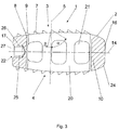
図1は、本発明によるインプラントの実施形態を示す斜視図である。
図2は、本発明によるインプラントの図1に示されている実施形態を示す第1の断面図である。
図3は、保持器具を受入れる手段とともに本発明によるインプラントの図1および2に示されている実施形態を示す縦断面図である。
図4は、X線マーキングとともに本発明によるインプラントの実施形態を示す縦断面図である。
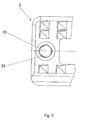
図5は、本発明によるインプラントの図4に示されている実施形態の後端を示す図面である。
(Brief description of the drawings)
FIG. 1 is a perspective view showing an embodiment of an implant according to the present invention.
FIG. 2 is a first sectional view showing the embodiment shown in FIG. 1 of an implant according to the invention.
FIG. 3 is a longitudinal section view of the embodiment shown in FIGS. 1 and 2 of an implant according to the invention with means for receiving a holding device.
FIG. 4 is a longitudinal sectional view showing an embodiment of the implant according to the present invention together with an X-ray marking.
FIG. 5 shows the rear end of the embodiment shown in FIG. 4 of an implant according to the invention.
図1〜3においては、両方の隣接する椎体のベースもしくはカバー面に配置するための上部および下部の凸状接触面3、4を有する切石状の本体2、および接触面3、4と交差する中心軸5を含んで成るインプラント1の実施形態が示されている。接触面3、4に対して横方向に2つの横側面18、19のほか、前方側面16および後方側面17が配置されている。中心軸5に対して直交に位置する長手方向軸14は両方の側面16、17と交差するが、同じく本体2の中心軸5に対して直交に位置する横軸15は両方の横側面18、19と交差する。長手方向軸14および横軸15は、接触面3、4間に中心軸5に対して直交に位置する中央面6を画定する。
本体2は、その中心軸5に対して平行に上部接触面3から下部接触面4まで開口20によって貫通される。横軸15に対して平行に本体2は3つの小穴によって第1の横側面18から第2の横側面19まで貫通される。したがって、本体2は、中心空洞を有するフレーム状の形態を有し、ここで前方および後方側面16、17は空洞へ流入する穴または開口を有さない。本体の中心軸5および長手方向軸14によって、第1の断面10が画定され、本体2の中心軸5および横軸15によって画定される第2の断面11とのその交線が本体2の中心軸5と一致する。
1-3, intersecting the
The
接触面3、4には歯7が備えられており、その中心軸34は本体2の中央面36に対して傾斜して位置している。この場合、歯7は、その中心軸34が本体2の長手方向軸14に対して直交の断面で見て上部接触面3で角度+φを含み、かつ下部接触面4で角度−φを中央面36と含むように構成されている。歯7は、第1の断面10に対して平行の断面で見て同じ方向にそれぞれ1つの険しく傾斜したフランクと穏やかに傾斜したフランク8、9を有し、かつ第2の断面11に対して平行の断面で見て接触面3、4ごとに同じ方向にそれぞれ1つの険しく傾斜したフランクおよび穏やかに傾斜したフランク12、13を有し、ここで、
−険しく傾斜したフランク8は第1の横断面10に対して平行の断面で見て本体2の中心軸5に対して平行の直線と角度βを含み、
−平坦なフランク9は第1の横断面10に対して平行の断面で見て本体2の中心軸5に対して平行の直線と角度αを含み、
−険しく傾斜したフランク12は第2の横断面11に対して平行の断面で見て本体2の中心軸5に対して平行の直線と上部接触面3で角度+δを、下部接触面4で角度−δを含み、かつ
−平坦なフランク13は第2の横断面11に対して平行の断面で見て本体2の中心軸5に対して平行の直線と上部接触面3で角度+γを、下部接触面4で角度−γを含む。
険しく傾斜したフランク8は、両方の接触面3、4において歯7の後方側面17に向いた側面上に位置している。第2の横断面11においては、歯7の険しく傾斜したフランク12が上部接触面3で長手方向軸14に対して平行に前方側面16から見て歯7の右側に配置されているが、歯7の険しく傾斜したフランク12は下部接触面4で同じく長手方向軸14に対して平行に前方側面16から見て歯7の左側に配置されている。
ここで示されている実施形態においては、険しく傾斜したフランク8、12と中心軸5に対して平行の直線との間の角度βおよびδは同じ大きさである。同様に、平坦なフランク9、13と本体2の中心軸5に対して平行の直線との間の角度αおよびγは同じ大きさである。
The contact surfaces 3 and 4 are provided with
The steeply
The
The steeply
The steeply
In the embodiment shown here, the angles β and δ between the steeply
第1の横断面10における険しく傾斜したフランク8の配置は、前方側面16を有するインプラント1があらかじめ椎間腔へ挿入され、隣接する椎体のベースもしくはカバープレートが歯7の平坦なフランク9によって別々に加圧されると同時に、移植された本体2の起こりうる滑り落ちが険しく傾斜したフランク8によって阻止されるようになっている。さらに、第2の横断面11における険しく傾斜したフランク12の配置は、椎間腔へ挿入されたインプラント1の右回転に際して、隣接する椎体のベースもしくはカバープレートが歯7の平坦なフランク13によって別々に加圧されると同時に、移植された本体2の左回転が険しく傾斜したフランク12によって阻止されるようになっている。
本体2は、移植に際して右回転を容易にするために接触面3、4と横側面18、19との間に2つの異なる半径を有する丸味部23を有する。丸味部23は、長手方向軸14に対して直交の第2の横断面11において対角でのみ位置するように配置されているため、丸味部23は上部接触面3と第1の横側面18との間、および下部接触面4と第2の横側面19との間に配置されている。2つの接触面3、4上の歯7に対して、丸味部23は平坦なフランク9、13を有する側に取付けられている。同様に、本体2はインプラント1の椎間腔へのより簡単な導入のために接触面3、4と前方側面16との間に第2の丸味部24を有する。
さらに、インプラント1はその後方端28に配置された、保持器具の回転固定受入れのための手段22を含んで成る。図3に示されている実施形態においては、保持器具を受入れるための手段22は、インプラント1の後方側面17から保持器具へ貫通する雌ネジ26を有する長手方向軸14に対して同軸の穴25を含んで成る。保持器具が回転固定でインプラント1と結合可能であるために、同じく後方側面17から貫通する、横軸15に対して平行に走る導管27がインプラント1に取付けられている。保持器具とインプラント1との回転固定結合のために、保持器具の雄ネジが備えられた部分が雌ネジ26へネジ込まれ、次いで導管27に相補的な部分が導管27へ導入される。
The arrangement of the steeply
The
Furthermore, the
手術過程の説明:
外科医が手術に必要な器具で椎間板腔へ貫通しうるために、最初に隣接するファセット関節および板を部分的に除去する。次いで、試験片によってインプラント1の必要な大きさを決定する。このようにして選択されたインプラント1を、インプラント1の後方端28に固定可能な適切な保持器具(図示せず)と結合する。インプラント1の導入は、歯7が備えられていない横側面18、19が隣接する椎体のカバーもしくはベース面に対して平行に配置されるように行われる。次いで、椎体の部分的に切除された背側構造物を通じて、インプラント1は椎間腔へ導入されうる。インプラント1を所望の深さまで椎間腔へ導入した後、外科医はインプラント1を保持器具によって長手方向軸15の周りを90°回転させ、歯7が備えられている接触面3、4はカバーもしくはベースプレートに定着されることになる。インプラント1の回転によって、外科医は脊柱の前方構造物への伸延を達成する。こうして、とりわけ脊椎前彎が再建されうる。同じ手術ステップで最後に第2のインプラント1を導入し、脊髄の両側にインプラント1が配置される。
図4および5に示された本発明によるインプラント1の実施形態は、2つのX線マーキング35を含んで成る。これらのX線マーキング35は、穴32へ導入されるピン31として構成されている。ピン31の穴32への固定のために、ピン31には周辺、および好ましくは、軸方向の中心にそれぞれ3つの隆起部30が備えられている。隆起部30は、ピン31の穴32への圧入中に可塑性に変形されるため、ピン31は穴32への圧入によって保持される。ここで示された実施形態においては、本体2は2つの穴32を有し、そのうち1つの穴32はインプラント1の前方端29に、もう1つの穴32はインプラント1の後方端28に配置されている。穴32は、その穴軸33が中心軸5に対して平行に、かつ中心軸5および長手方向軸14によって伸張した平面に位置するように構成されている。
Description of the surgical process:
In order to allow the surgeon to penetrate the disc space with the instruments necessary for the operation, the adjacent facet joint and plate are first partially removed. Next, the required size of the
The embodiment of the
1 インプラント 2 本体 3 上部接触面 4 歯 5 中心軸
6 中央面 7 歯 8 フランク 9 フランク 10 断面
11 断面 12 フランク 13 フランク 14 長手方向軸
15 横軸 16 側面 17 側面 18 横側面 19 横側面
23 丸味部 24 丸味部 30 隆起部 31 ピン 32 穴
33 穴軸 34 中心軸 35 X線マーキング 36 中央面
DESCRIPTION OF
Claims (33)
A)前記インプラント(1)に接触するよう構成される椎体の上部の基板へ配置する上部凸状接触面(3)、前記インプラント(1)に接触するよう構成される椎体の下部の基板へ配置する下部凸状接触面(4)、
B)前記上部および下部接触面(3、4)の横方向に配置された2つの横側面(18、19)、
C)前後の側面(16、17)、前記2つの接触面(3、4)に交差する中心軸(5)、前記前後の側面(16、17)に交差する長手方向軸(14)および前記横側面(18、19)に交差する横軸(15)と、
D)前記接触面(3、4)間に位置する、前記本体(2)の中心軸(5)に対して垂直に位置する中央面(36)とを有し、
E)前記接触面(3、4)が、中心軸(34)を有する少なくとも部分的に肉眼で見える歯(7)を有する前記インプラント(1)において、
F)前記歯(7)の前記中心軸(34)が前記中央面(36)に対して、前記本体(2)の長手方向軸(14)の周りの90°の回転が1つの回転方向で有利であり、他の回転方向で困難となるように傾斜して位置しており、
G)前記歯(7)が傾斜したピラミッドまたは傾斜した円錐として、それぞれ傾斜した先端が切られたピラミッドまたは傾斜した先端が切られた円錐として形成され、かつ
H)前記両方の横側面(18、19)間の距離が、前記両方の接触面(3、4)間の距離よりも小さい
ことを特徴とするインプラント(1)。An implant (1) for an intervertebral space comprising a substantially calcite-shaped body (2), comprising:
A) Upper convex contact surface (3) disposed on the upper substrate of the vertebral body configured to contact the implant (1), lower substrate of the vertebral body configured to contact the implant (1) The lower convex contact surface (4),
B) Two lateral sides (18, 19) arranged laterally of the upper and lower contact surfaces (3, 4 ),
C) front and rear side surfaces (16, 17), central axis (5) intersecting the two contact surfaces (3, 4), longitudinal axis (14) intersecting the front and rear side surfaces (16, 17) and A horizontal axis (15) intersecting the lateral sides (18, 19);
D) a central surface (36) located between the contact surfaces (3, 4) and perpendicular to the central axis (5) of the body (2);
E) In the implant (1), wherein the contact surface (3, 4) comprises at least partially visible teeth (7) having a central axis (34)
F) 90 ° rotation about the longitudinal axis (14) of the body (2) in one rotational direction with respect to the central surface (36), the central axis (34) of the teeth (7) Advantageous, tilted to be difficult in other directions of rotation,
G) the tooth (7) is formed as an inclined pyramid or inclined cone, as a truncated pyramid or inclined tip, respectively, as an inclined pyramid or inclined cone;
H) Implant (1), characterized in that the distance between the two lateral surfaces (18, 19) is smaller than the distance between the two contact surfaces (3, 4).
b)前記下部接触面(4)では前記緩やかに傾斜したフランク(13)が、前記長手方向軸(14)に対して直交の断面で見て前記本体(2)の前記中心軸(5)に対して平行の直線とともに角度−γを含み、かつ前記険しく傾斜したフランク(12)が同じ直線とともに角度−δを含むことを特徴とする請求項7〜11のいずれか1つに記載のインプラント(1)。a) On the upper contact surface (3), the gently inclined flank (13) is located on the central axis (5) of the body (2) when viewed in a cross section perpendicular to the longitudinal axis (14). And the steeply inclined flank (12) includes an angle + δ together with a straight line parallel to the straight line, and b) the gently inclined flank (13) on the lower contact surface (4) The steeply inclined flank (12) including an angle -γ with a straight line parallel to the central axis (5) of the body (2) when viewed in a cross-section perpendicular to the longitudinal axis (14) 12) The implant (1) according to any one of claims 7 to 11 , characterized in that it includes an angle -δ together with the same straight line.
Applications Claiming Priority (1)
| Application Number | Priority Date | Filing Date | Title |
|---|---|---|---|
| PCT/CH2003/000412 WO2004112660A1 (en) | 2003-06-24 | 2003-06-24 | Implant for the intervertebral space |
Publications (3)
| Publication Number | Publication Date |
|---|---|
| JP2007504843A JP2007504843A (en) | 2007-03-08 |
| JP2007504843A5 JP2007504843A5 (en) | 2009-09-17 |
| JP4378343B2 true JP4378343B2 (en) | 2009-12-02 |
Family
ID=33520332
Family Applications (1)
| Application Number | Title | Priority Date | Filing Date |
|---|---|---|---|
| JP2005500844A Expired - Lifetime JP4378343B2 (en) | 2003-06-24 | 2003-06-24 | Intervertebral space implant |
Country Status (11)
| Country | Link |
|---|---|
| US (2) | US8012208B2 (en) |
| EP (1) | EP1635743A1 (en) |
| JP (1) | JP4378343B2 (en) |
| CN (1) | CN1787794A (en) |
| AR (1) | AR044792A1 (en) |
| AU (1) | AU2003240354A1 (en) |
| BR (1) | BR0318328A (en) |
| CA (1) | CA2530730A1 (en) |
| CL (1) | CL2004001388A1 (en) |
| TW (1) | TW200505387A (en) |
| WO (1) | WO2004112660A1 (en) |
Families Citing this family (29)
| Publication number | Priority date | Publication date | Assignee | Title |
|---|---|---|---|---|
| CN100591305C (en) | 2004-02-13 | 2010-02-24 | 小弗朗茨·科波夫 | Intervertebral implant and surgical method for spondyilodesis of a lumbar vertebral column |
| US7918891B1 (en) * | 2004-03-29 | 2011-04-05 | Nuvasive Inc. | Systems and methods for spinal fusion |
| DE102005024927B4 (en) * | 2005-05-23 | 2007-07-12 | Ohst Medizintechnik Ag | A vertebral implant for insertion into a vertebral space |
| US20060293748A1 (en) * | 2005-06-24 | 2006-12-28 | Spineworks, Llc | Prosthetic implant, and a method and tool for the insertion of same |
| US8623088B1 (en) * | 2005-07-15 | 2014-01-07 | Nuvasive, Inc. | Spinal fusion implant and related methods |
| US20070270963A1 (en) * | 2006-04-27 | 2007-11-22 | Sdgi Holdings, Inc. | Intervertebral implants and methods of use |
| US8002837B2 (en) | 2006-05-19 | 2011-08-23 | Pioneer Surgical Technology | Spinal stabilization device and methods |
| USD741488S1 (en) | 2006-07-17 | 2015-10-20 | Nuvasive, Inc. | Spinal fusion implant |
| US8801791B2 (en) * | 2006-09-27 | 2014-08-12 | K2M, Inc. | Spinal interbody spacer |
| TW200916071A (en) * | 2007-10-08 | 2009-04-16 | Topasia Internat Technology Inc | Spinal filler |
| JP5266069B2 (en) * | 2008-02-07 | 2013-08-21 | 昭和医科工業株式会社 | cage |
| EP2149352A1 (en) * | 2008-07-29 | 2010-02-03 | DERU GmbH | Intervertebral Implant |
| JP5455020B2 (en) * | 2009-06-08 | 2014-03-26 | ナカシマメディカル株式会社 | Intervertebral cage |
| USD731063S1 (en) | 2009-10-13 | 2015-06-02 | Nuvasive, Inc. | Spinal fusion implant |
| US9358122B2 (en) | 2011-01-07 | 2016-06-07 | K2M, Inc. | Interbody spacer |
| US9095445B2 (en) * | 2011-07-14 | 2015-08-04 | Warsaw Orthopedic, Inc. | Vertebral interbody spacer |
| US9132021B2 (en) | 2011-10-07 | 2015-09-15 | Pioneer Surgical Technology, Inc. | Intervertebral implant |
| US9655746B2 (en) | 2011-11-09 | 2017-05-23 | Globus Medical, Inc. | Intervertebral spinal implant |
| US9034043B2 (en) * | 2012-02-03 | 2015-05-19 | Zimmer Spine, Inc. | Intervertebral implant and insertion instrument |
| EP2724692B1 (en) * | 2012-10-24 | 2015-05-20 | WALDEMAR LINK GmbH & Co. KG | Holder for a medical implant |
| US9149367B2 (en) | 2013-03-15 | 2015-10-06 | Globus Medical Inc | Expandable intervertebral implant |
| ITMI20131453A1 (en) * | 2013-09-05 | 2015-03-06 | Francesco Ugo Prada | ULTRA-COMPATIBLE ARTIFICIAL CRANIOTOMIC OPERCOLO |
| US9730802B1 (en) | 2014-01-14 | 2017-08-15 | Nuvasive, Inc. | Spinal fusion implant and related methods |
| US10555818B2 (en) | 2015-04-23 | 2020-02-11 | Institute for Musculoskeletal Science and Education, Ltd. | Spinal fusion implant for oblique insertion |
| US10292825B2 (en) * | 2016-06-27 | 2019-05-21 | Globus Medical, Inc. | Intervertebral spacer with chamfered edges |
| US10292834B2 (en) * | 2016-06-27 | 2019-05-21 | Globus Medical, Inc. | Intervertebral spacer with chamfered edges |
| ES2963731T3 (en) | 2016-09-27 | 2024-04-01 | Gliaview Llc | Ultrasound Compatible Modulated Artificial Cranial Prosthesis |
| CA3074834A1 (en) | 2017-09-08 | 2019-03-14 | Pioneer Surgical Technology, Inc. | Intervertebral implants, instruments, and methods |
| USD907771S1 (en) | 2017-10-09 | 2021-01-12 | Pioneer Surgical Technology, Inc. | Intervertebral implant |
Family Cites Families (14)
| Publication number | Priority date | Publication date | Assignee | Title |
|---|---|---|---|---|
| US4834757A (en) | 1987-01-22 | 1989-05-30 | Brantigan John W | Prosthetic implant |
| EP0388576B1 (en) * | 1989-03-23 | 1993-09-15 | Institut Straumann Ag | Metallic implant |
| US5425772A (en) * | 1993-09-20 | 1995-06-20 | Brantigan; John W. | Prosthetic implant for intervertebral spinal fusion |
| BE1007549A3 (en) | 1993-09-21 | 1995-08-01 | Beckers Louis Francois Charles | Implant. |
| US5766253A (en) * | 1996-01-16 | 1998-06-16 | Surgical Dynamics, Inc. | Spinal fusion device |
| US5865845A (en) * | 1996-03-05 | 1999-02-02 | Thalgott; John S. | Prosthetic intervertebral disc |
| FR2764795B1 (en) * | 1997-06-19 | 1999-09-10 | Sarl Sra | INTERSOMATIC RACHIS IMMOBILIZATION CAGE AND ASSOCIATED ANCILLARY MATERIAL |
| WO2000007527A1 (en) * | 1998-08-03 | 2000-02-17 | Synthes Ag Chur | Intervertebral allograft spacer |
| ATE293411T1 (en) * | 1998-10-30 | 2005-05-15 | Michelson Gary K | SELF-REAVING, ROTATABLE, INSERTABLE SPONDYLOSUS IMPLANT |
| CA2361068A1 (en) * | 1999-02-04 | 2000-08-10 | Sdgi Holdings, Inc. | Improved interbody fusion device with anti-rotation features |
| EP1194086A4 (en) * | 1999-06-08 | 2003-03-19 | Osteotech Inc | Keyed intervertebral dowel |
| JP2003527196A (en) * | 2000-03-22 | 2003-09-16 | スコリオ ゲーエムベーハー | Cage-type intervertebral implant |
| FR2816201B1 (en) * | 2000-11-07 | 2003-08-01 | Medicrea | INTERVERTEBRAL CAGE AND INSTRUMENT FOR PLACING THIS CAGE BETWEEN TWO VERTEBRES |
| EP2161008B1 (en) * | 2003-05-27 | 2014-12-24 | Simplify Medical, Inc. | Method for assembling a prosthetic disc for intervertebral insertion |
-
2003
- 2003-06-24 CA CA002530730A patent/CA2530730A1/en not_active Abandoned
- 2003-06-24 WO PCT/CH2003/000412 patent/WO2004112660A1/en active Application Filing
- 2003-06-24 AU AU2003240354A patent/AU2003240354A1/en not_active Abandoned
- 2003-06-24 BR BRPI0318328-9A patent/BR0318328A/en not_active IP Right Cessation
- 2003-06-24 CN CNA038266814A patent/CN1787794A/en active Pending
- 2003-06-24 EP EP03729770A patent/EP1635743A1/en not_active Withdrawn
- 2003-06-24 JP JP2005500844A patent/JP4378343B2/en not_active Expired - Lifetime
-
2004
- 2004-06-03 TW TW093115933A patent/TW200505387A/en unknown
- 2004-06-04 CL CL200401388A patent/CL2004001388A1/en unknown
- 2004-06-17 AR ARP040102102A patent/AR044792A1/en not_active Application Discontinuation
-
2005
- 2005-12-22 US US11/318,937 patent/US8012208B2/en active Active
-
2011
- 2011-08-30 US US13/221,375 patent/US8617247B2/en not_active Expired - Lifetime
Also Published As
| Publication number | Publication date |
|---|---|
| WO2004112660A1 (en) | 2004-12-29 |
| EP1635743A1 (en) | 2006-03-22 |
| CN1787794A (en) | 2006-06-14 |
| CL2004001388A1 (en) | 2005-03-11 |
| AU2003240354A1 (en) | 2005-01-04 |
| CA2530730A1 (en) | 2004-12-29 |
| TW200505387A (en) | 2005-02-16 |
| US20060195190A1 (en) | 2006-08-31 |
| US20110313531A1 (en) | 2011-12-22 |
| BR0318328A (en) | 2006-07-11 |
| US8617247B2 (en) | 2013-12-31 |
| AR044792A1 (en) | 2005-10-05 |
| US8012208B2 (en) | 2011-09-06 |
| JP2007504843A (en) | 2007-03-08 |
Similar Documents
| Publication | Publication Date | Title |
|---|---|---|
| JP4378343B2 (en) | Intervertebral space implant | |
| US20200121469A1 (en) | Intervertebral Implant with Fixation Geometry | |
| US5306308A (en) | Intervertebral implant | |
| JP5975530B2 (en) | Arcuate fixation member and intervertebral implant | |
| CN101330886B (en) | Facet joint prosthesis | |
| US6520993B2 (en) | Spinal implant | |
| EP1617793B1 (en) | Interbody fusion device | |
| US8636805B2 (en) | Artificial intervertebral disc placement system | |
| US8257443B2 (en) | Open body box form interbody fusion cage | |
| KR101173195B1 (en) | allograft implant | |
| EP1849437B1 (en) | Dual composition vertebral fixation device | |
| CN103648421A (en) | Vertebral interbody spacer | |
| KR20080010406A (en) | Spinal implant | |
| US11241318B2 (en) | Intervertebral implant and insertion device therefor | |
| JP5119165B2 (en) | Face joint prosthesis | |
| KR100861396B1 (en) | Implant for the intervertebral space |
Legal Events
| Date | Code | Title | Description |
|---|---|---|---|
| A711 | Notification of change in applicant |
Free format text: JAPANESE INTERMEDIATE CODE: A711 Effective date: 20061219 |
|
| RD02 | Notification of acceptance of power of attorney |
Free format text: JAPANESE INTERMEDIATE CODE: A7422 Effective date: 20080117 |
|
| A131 | Notification of reasons for refusal |
Free format text: JAPANESE INTERMEDIATE CODE: A131 Effective date: 20081126 |
|
| A02 | Decision of refusal |
Free format text: JAPANESE INTERMEDIATE CODE: A02 Effective date: 20090401 |
|
| A524 | Written submission of copy of amendment under article 19 pct |
Free format text: JAPANESE INTERMEDIATE CODE: A524 Effective date: 20090801 |
|
| A911 | Transfer to examiner for re-examination before appeal (zenchi) |
Free format text: JAPANESE INTERMEDIATE CODE: A911 Effective date: 20090807 |
|
| TRDD | Decision of grant or rejection written | ||
| A01 | Written decision to grant a patent or to grant a registration (utility model) |
Free format text: JAPANESE INTERMEDIATE CODE: A01 Effective date: 20090904 |
|
| A01 | Written decision to grant a patent or to grant a registration (utility model) |
Free format text: JAPANESE INTERMEDIATE CODE: A01 |
|
| A61 | First payment of annual fees (during grant procedure) |
Free format text: JAPANESE INTERMEDIATE CODE: A61 Effective date: 20090914 |
|
| R150 | Certificate of patent or registration of utility model |
Ref document number: 4378343 Country of ref document: JP Free format text: JAPANESE INTERMEDIATE CODE: R150 Free format text: JAPANESE INTERMEDIATE CODE: R150 |
|
| FPAY | Renewal fee payment (event date is renewal date of database) |
Free format text: PAYMENT UNTIL: 20120918 Year of fee payment: 3 |
|
| FPAY | Renewal fee payment (event date is renewal date of database) |
Free format text: PAYMENT UNTIL: 20130918 Year of fee payment: 4 |
|
| R250 | Receipt of annual fees |
Free format text: JAPANESE INTERMEDIATE CODE: R250 |
|
| R250 | Receipt of annual fees |
Free format text: JAPANESE INTERMEDIATE CODE: R250 |
|
| R250 | Receipt of annual fees |
Free format text: JAPANESE INTERMEDIATE CODE: R250 |
|
| R250 | Receipt of annual fees |
Free format text: JAPANESE INTERMEDIATE CODE: R250 |
|
| R250 | Receipt of annual fees |
Free format text: JAPANESE INTERMEDIATE CODE: R250 |
|
| R250 | Receipt of annual fees |
Free format text: JAPANESE INTERMEDIATE CODE: R250 |
|
| R250 | Receipt of annual fees |
Free format text: JAPANESE INTERMEDIATE CODE: R250 |
|
| R250 | Receipt of annual fees |
Free format text: JAPANESE INTERMEDIATE CODE: R250 |
|
| R250 | Receipt of annual fees |
Free format text: JAPANESE INTERMEDIATE CODE: R250 |
|
| R250 | Receipt of annual fees |
Free format text: JAPANESE INTERMEDIATE CODE: R250 |
|
| R250 | Receipt of annual fees |
Free format text: JAPANESE INTERMEDIATE CODE: R250 |
|
| EXPY | Cancellation because of completion of term |