JP4377249B2 - Ink consumption reduction error diffusion - Google Patents
Ink consumption reduction error diffusion Download PDFInfo
- Publication number
- JP4377249B2 JP4377249B2 JP2004007224A JP2004007224A JP4377249B2 JP 4377249 B2 JP4377249 B2 JP 4377249B2 JP 2004007224 A JP2004007224 A JP 2004007224A JP 2004007224 A JP2004007224 A JP 2004007224A JP 4377249 B2 JP4377249 B2 JP 4377249B2
- Authority
- JP
- Japan
- Prior art keywords
- anchor
- error
- color
- error diffusion
- ink
- Prior art date
- Legal status (The legal status is an assumption and is not a legal conclusion. Google has not performed a legal analysis and makes no representation as to the accuracy of the status listed.)
- Expired - Fee Related
Links
Images


Classifications
-
- H—ELECTRICITY
- H04—ELECTRIC COMMUNICATION TECHNIQUE
- H04N—PICTORIAL COMMUNICATION, e.g. TELEVISION
- H04N1/00—Scanning, transmission or reproduction of documents or the like, e.g. facsimile transmission; Details thereof
- H04N1/46—Colour picture communication systems
- H04N1/52—Circuits or arrangements for halftone screening
Description
本発明は、印刷技術に関し、より詳細には、ハーフトーン処理を利用したカラー文書の印刷に使用されるインクまたはトナーの使用量を抑える技術に関する。 The present invention relates to a printing technique, and more particularly to a technique for reducing the amount of ink or toner used for printing a color document using halftone processing.
プリンタやコピー機の利用においてインクまたはトナーに関するコストは無視できない要素である。このため、それらの使用量を抑えることにより全体のランニングコストを低減することができる。一般に、インク使用量はページの印刷コストのかなりの部分を占めている。より少ないインク使用量で各ページの印刷が可能となれば、このインク使用量の節約によりトータルコストを低減させることができるであろう。また、紙のリサイクル処理において、インク使用量の低減は有害な化学物質の利用を抑えることができ、結果として環境への負荷を減らすことにもつながる。さらに、この紙のリサイクル処理は流体処理(hydrodynamic process)であり、インク使用量の低減は水の利用を抑えると共に、当該処理に要するエネルギーの減少をももたらすであろう。 The cost associated with ink or toner is a factor that cannot be ignored in the use of a printer or copier. For this reason, the whole running cost can be reduced by suppressing those usage-amounts. In general, ink usage is a significant part of the printing cost of a page. If printing of each page becomes possible with a smaller amount of ink used, the total cost can be reduced by saving the amount of ink used. Further, in paper recycling, the reduction in ink usage can suppress the use of harmful chemical substances, resulting in a reduction in environmental impact. Furthermore, this paper recycling process is a hydrodynamic process, and a reduction in ink usage will reduce water usage and reduce the energy required for the process.
このようにインク使用量を抑えることは望ましい結果をもたらす一方、現在のカラープリンタはインクの効率的な利用を行っていない。インク使用量を減少させるための方法としては、画質維持と共にインク使用量を抑えるドラフトモード技術(draft mode technology)、プレハーフトーン処理技術(pre-halftoning technology)及びハーフトーン処理アルゴリズムなどが含まれる。ドラフトモード技術に関して、現在のプリンタは、画質を落とすことによりインク使用量を抑える「ドラフト」オプションを提供している。例えば、ハーフトーン処理前に、8ビットのC、M、Y及びKの各値の輝度を1/2にしたり、あるいは画像の彩度を減少させて、交互に画素を印刷することによりドラフト文書の印刷が行われる。ドラフト印刷では文書の画質が落ちるため、カラープリンタやカラーコピー機ではインク使用量の低減の効果は限られたものとなってしまう。 While reducing the amount of ink used in this way has desirable results, current color printers do not make efficient use of ink. Methods for reducing ink usage include draft mode technology, pre-halftoning technology, and halftone processing algorithms that maintain image quality and reduce ink usage. With respect to draft mode technology, current printers offer a “draft” option that reduces ink usage by reducing image quality. For example, before halftone processing, draft documents can be created by printing pixels alternately by halving the brightness of each of the 8-bit C, M, Y, and K values or reducing the saturation of the image. Is printed. In draft printing, the image quality of a document is lowered, so that the effect of reducing the amount of ink used is limited in color printers and color copiers.
他の従来技術では、ハーフトーン処理前に8ビットのデータの変換あるいは制限が行われる。例えば、2001年11月6日Deckerらに与えられた米国特許第6,313,925号「画質劣化なくカラープリンタにおけるトナー/インク使用量を低減させるシステム、方法及びプログラム(System, Method and Program for Saving Toner/Ink in a Color Printer Without Sacrificing Image Quality)」を参照されたい。特殊な下色除去関数(undercolor removal function)が利用される。 In other conventional techniques, 8-bit data is converted or limited before halftone processing. For example, US Pat. No. 6,313,925 issued to Decker et al. On Nov. 6, 2001, “System, Method and Program for Saving Toner / Ink”. in a Color Printer Without Sacrificing Image Quality). A special undercolor removal function is used.
従来技術において、ドットゲインを補償する誤差拡散(error diffusion)が修正されてきた。例えば、Henry Kangによる「デジタルカラーハーフトーン処理(Digital Color Halftoning)」(SPIE Press, 2001)及びJoseph Shuによる「高画質高解像度インクジェット印刷のためのインク抑制による誤差拡散(Error Diffusion With Ink Reduction for High Quality and High Resolution Ink Jet Printing)」(IEEE International Conference on Image Processing, 1995)を参照されたい。この中でShuは彼のアルゴリズムを「インク抑制による誤差拡散」と呼んでいる。インクジェットメディアのインク溢れを回避し、ウォームアーチファクト(worm-artifact)を抑えるためのインクを抑制するために、ドットゲインが補償される。Shuによる研究はまた特許形式でも与えられている。1997年1月7日Shuに与えられた米国特許第5,592,592号「インク抑制処理を利用した誤差拡散ハーフトーン処理による画像におけるアーチファクトを最小化するための方法及び装置(Method and Apparatus for Minimizing Artifacts in Images Produced by Error Diffusion Halftoning Utilizing Ink Reduction Processing)」を参照されたい。 In the prior art, error diffusion to compensate for dot gain has been corrected. For example, “Digital Color Halftoning” by Henry Kang (SPIE Press, 2001) and “Error Diffusion With Ink Reduction for High for high-quality, high-resolution inkjet printing” by Joseph Shu. Quality and High Resolution Ink Jet Printing ”(IEEE International Conference on Image Processing, 1995). In this, Shu calls his algorithm “error diffusion by ink suppression”. In order to avoid ink overflow of inkjet media and to suppress ink to reduce worm-artifact, dot gain is compensated. Research by Shu is also given in patent form. U.S. Pat. No. 5,592,592, issued to Shu on Jan. 7, 1997, “Method and Apparatus for Minimizing Artifacts in Images” Refer to “Produced by Error Diffusion Halftoning Utilizing Ink Reduction Processing”.
他の関連技術としては、K重複印刷を防ぐハーフトーン処理アルゴリズムである。多くのディザ方法がある。例えば、1995年12月5日にPerumalらに与えられた米国特許第5,473,446号「黒及び補助色置換及びカラーベクトルディザ処理を利用したカラーデジタルハーフトーン処理(Color Digital Halftoning Using Black and Secondary Color Replacement and Color Vector Dithering)」を参照されたい。 Another related technique is a halftone processing algorithm that prevents K-duplicated printing. There are many dither methods. For example, U.S. Pat. No. 5,473,446 issued to Perumal et al. On Dec. 5, 1995, "Color Digital Halftoning Using Black and Secondary Color Replacement and Refer to “Color Vector Dithering”.
1994年7月26日にBestらに与えられた米国特許第5,333,243号「ヒュー=プラス=グレイカラーモデル及び誤差拡散を利用したカラー画像形成方法(Method for Forming Color Images Using a Hue-Plus-Gray Color Model and Error Diffusion)」では、R、G、B、C、M、Y、K及びWの1色のみが一度に印刷される新規な誤差拡散方法が開示されている。これにより、色のトップにKを印刷する可能性を排除している。当該システムでは、どの色が現時点で最も大きな誤差を有しているかに着目することにより、印刷すべき色を決定している。誤差は通常の誤差拡散と同じようにパスされる。このような方法では、入力に対し特殊な下色除去あるいは制限が要求されるか、あるいはそうでなければ誤差は溢れ出てしまうであろう。例えば、この方法によると、CMYK入力値(255,0,0,50)はさらに大きな誤差を引き起こすことになるであろう。 US Pat. No. 5,333,243 granted to Best et al. On July 26, 1994 “Method for Forming Color Images Using a Hue-Plus-Gray Color Model and Error Diffusion) discloses a novel error diffusion method in which only one color of R, G, B, C, M, Y, K, and W is printed at a time. This eliminates the possibility of printing K on top of the color. In this system, the color to be printed is determined by paying attention to which color has the largest error at the present time. The error is passed in the same way as normal error diffusion. Such a method would require special undercolor removal or restriction on the input, or otherwise the error would overflow. For example, according to this method, the CMYK input value (255, 0, 0, 50) will cause a larger error.
1995年5月28日にMottaらに与えられた米国特許第5,402,245号「改善された下色除去及びエラー拡散手順を示すバイレベルデジタルカラープリンタシステム(Bi-level digital color printer system exhibiting improved undercolor removal and error diffusion procedures)」では、入力値Kが最大の入力値であるかに基づくことなく、それが誤差拡散閾値より大きければ、最初にKを印刷するという決定がなされる誤差拡散アルゴリズムが開示される。Kを印刷するよう決定される場合、他の色C、M及びYは考慮されない。誤差が溢れ出ないように、入力に対し特殊な下色除去あるいは制限が再び必要となる。例えば、この方法によると、CMYK入力値(50,0,0,255)はさらに大きな誤差を引き起こすことになるであろう。 US Pat. No. 5,402,245 issued May 28, 1995 to Motta et al. “Bi-level digital color printer system exhibiting improved undercolor removal and error diffusion procedures) discloses an error diffusion algorithm in which, based on whether the input value K is the maximum input value, if it is greater than the error diffusion threshold, a decision is made to print K first. . If it is decided to print K, the other colors C, M and Y are not considered. In order to prevent errors from overflowing, special undercolor removal or restriction is required again for the input. For example, according to this method, the CMYK input value (50,0,0,255) will cause a larger error.
MottaとDispotoによる研究では、量子化器と出力ハーフトーン信号とのマッピングのアイデアが取り入れられている。この研究では、量子化、誤差計算及び誤差分布からなる誤差拡散ステップが、CIELabやRGB空間のような1つの空間で行われ、量子化器からの出力が印刷装置空間の適切な色にマッピングされる。1997年5月15日にMottaらに与えられた米国特許第5,621,545号「色誤差拡散を利用した画像生成(Image production using color error diffusion)」を参照されたい。しかしながら、当該特許はCMY空間へのマッピングのみにしか言及していない。
本発明は、上記問題点に鑑み、ハーフトーン処理を利用したカラー文書の印刷に使用されるインク及びトナー使用量を減少させる方法及び装置を提供することを目的とする。 In view of the above problems, an object of the present invention is to provide a method and apparatus for reducing the amount of ink and toner used for printing a color document using halftone processing.
上記課題を解決するため、本発明による方法は、ベクトル誤差拡散を実行するステップ、及びアンカーに印刷カラーをマッピングするステップからなる方法であって、前記ベクトル誤差拡散を実行するステップは、各入力画素値をアンカーセットの最近接アンカーに量子化するステップと、前記入力画素値と前記アンカーとの差に基づき誤差を計算するステップと、前記計算された誤差に基づき誤差拡散を実行するステップとを有し、前記アンカーの1以上が前記印刷カラーの1つにマッピングされることを特徴とする。 In order to solve the above-mentioned problem, the method according to the present invention comprises a step of performing vector error diffusion and a step of mapping a printing color to an anchor, wherein the step of performing vector error diffusion is performed for each input pixel. Quantizing values into nearest anchors of an anchor set; calculating an error based on a difference between the input pixel value and the anchor; and performing error diffusion based on the calculated error. And one or more of the anchors are mapped to one of the printing colors.
さらに、上記課題を解決するため、本発明による装置は、ベクトル誤差拡散を実行する手段、及びアンカーに印刷カラーをマッピングする手段からなる装置であって、前記ベクトル誤差拡散を実行する手段は、各入力画素値をアンカーセットの最近接アンカーに量子化する手段と、前記入力画素値と前記アンカーとの差に基づき誤差を計算する手段と、前記計算された誤差に基づき誤差フィルタリングを実行する手段とを有し、前記アンカーの1以上が前記印刷カラーの1つにマッピングされることを特徴とする。 Furthermore, in order to solve the above-mentioned problem, an apparatus according to the present invention is an apparatus comprising means for performing vector error diffusion and means for mapping a printing color to an anchor, and the means for performing vector error diffusion includes: Means for quantizing an input pixel value into a nearest anchor of an anchor set; means for calculating an error based on a difference between the input pixel value and the anchor; and means for performing error filtering based on the calculated error And one or more of the anchors are mapped to one of the printing colors.
さらに、上記課題を解決するため、本発明による装置は、ベクトル誤差拡散を実行するベクトル誤差拡散部、及びアンカーに印刷カラーをマッピングするマッピングユニットからなる装置であって、前記ベクトル誤差拡散部は、各入力画素値をアンカーセットの最近接アンカーに量子化する量子化器と、該量子化器に接続され、前記入力画素値と前記アンカーとの差に基づき誤差を計算する誤差計算ユニットと、該誤差計算ユニットに接続され、前記計算された誤差に基づき誤差フィルタリングを実行するフィルタとを有し、前記アンカーの1以上が前記印刷カラーの1つにマッピングされ、アンカー数が印刷カラー数より多いことを特徴とする。 Furthermore, in order to solve the above-described problem, an apparatus according to the present invention includes a vector error diffusion unit that performs vector error diffusion, and a mapping unit that maps a print color to an anchor, and the vector error diffusion unit includes: A quantizer that quantizes each input pixel value to the nearest anchor of an anchor set; an error calculation unit that is connected to the quantizer and calculates an error based on a difference between the input pixel value and the anchor; A filter connected to an error calculation unit and performing error filtering based on the calculated error, wherein one or more of the anchors are mapped to one of the print colors, and the number of anchors is greater than the number of print colors It is characterized by.
さらに、上記課題を解決するため、本発明による方法は、少なくとも1つのブラックドットが1つ以上の他のカラードットとデジタル重複する複数のドットを生成するため、平面単位カラー誤差拡散を実行するステップ、及び前記少なくとも1つのブラックドットにデジタル重複するカラードットを除去するため、デジタル信号にインク使用量減少マッピングを実行するステップからなることを特徴とする。 Furthermore, to solve the above problem, the method according to the present invention comprises performing planar unit color error diffusion to generate a plurality of dots in which at least one black dot digitally overlaps with one or more other color dots. And a step of performing ink usage reduction mapping on the digital signal to remove color dots that are digitally overlapped with the at least one black dot.
さらに、上記課題を解決するため、本発明による装置は、少なくとも1つのブラックドットが1つ以上の他のカラードットとデジタル重複する複数のドットを生成するため、平面単位カラー誤差拡散を実行する誤差拡散ユニット、及び前記少なくとも1つのブラックドットにデジタル重複するカラードットを除去するため、デジタル信号にインク使用量減少マッピングを実行するインクマッピングユニットからなることを特徴とする。 Furthermore, in order to solve the above problems, the apparatus according to the present invention generates an error in which plane unit color error diffusion is performed in order to generate a plurality of dots in which at least one black dot is digitally overlapped with one or more other color dots. A diffusion unit and an ink mapping unit that performs mapping to reduce ink usage on a digital signal in order to remove color dots that are digitally overlapped with the at least one black dot.
さらに、上記課題を解決するため、本発明による方法は、少なくとも1つのブラックドットが1つ以上の他のカラードットと重複する複数のドットを生成するため、ディザ処理を実行するステップ、及び前記少なくとも1つのブラックドットにデジタル重複するカラードットを除去するため、デジタル信号にインク使用量減少マッピングを実行するステップからなることを特徴とする。 Furthermore, in order to solve the above problem, the method according to the present invention comprises performing a dithering process to generate a plurality of dots in which at least one black dot overlaps with one or more other color dots, and In order to remove a color dot that is digitally overlapped with one black dot, the method includes a step of performing ink use amount reduction mapping on the digital signal.
さらに、上記課題を解決するため、本発明による装置は、少なくとも1つのブラックドットが1つ以上の他のカラードットと重複する複数のドットを生成するため、ディザ処理を実行するディザユニット、及び前記少なくとも1つのブラックドットにデジタル重複するカラードットを除去するため、デジタル信号にインク使用量減少マッピングを実行するインクマッピングユニットからなることを特徴とする。 Furthermore, in order to solve the above problem, an apparatus according to the present invention includes a dither unit that performs dither processing to generate a plurality of dots in which at least one black dot overlaps with one or more other color dots, and It is characterized by comprising an ink mapping unit that performs ink usage reduction mapping on digital signals in order to remove color dots that overlap digitally with at least one black dot.
さらに、上記課題を解決するため、本発明による方法は、カラー画像データを解析し、非ブラックドットがブラックドットに重複しているか決定するステップ、ブラックドットに重複している1つ以上の非ブラックドットを除去することにより、前記カラー画像データを修正するステップ、及び前記修正されたカラー画像データに対応する出力画像を生成するステップからなることを特徴とする。 Furthermore, to solve the above problems, the method according to the present invention comprises analyzing the color image data and determining whether the non-black dots overlap the black dots, one or more non-black overlapping the black dots. The method includes a step of correcting the color image data by removing dots, and a step of generating an output image corresponding to the corrected color image data.
さらに、上記課題を解決するため、本発明による装置は、カラー画像データを解析し、非ブラックドットがブラックドットに重複しているか決定し、ブラックドットに重複している1つ以上の非ブラックドットを除去することにより、前記カラー画像データを修正するカラー除去器、及び前記修正されたカラー画像データに対応する出力画像を生成する画像生成装置からなることを特徴とする。 Furthermore, in order to solve the above problem, the apparatus according to the present invention analyzes color image data, determines whether non-black dots overlap with black dots, and one or more non-black dots overlapping with black dots. And a color remover for correcting the color image data, and an image generation apparatus for generating an output image corresponding to the corrected color image data.
さらに、上記課題を解決するため、本発明による方法は、ブラックカラー平面をハーフトーン処理し、結果を生成するステップ、及び前記結果とセグメンテーションデータを利用して、他のカラー平面をハーフトーン処理するステップからなることを特徴とする。 Further, to solve the above problem, the method according to the present invention includes a step of halftoning a black color plane and generating a result, and halftoning another color plane using the result and segmentation data. It consists of steps.
本発明によると、ハーフトーン処理を利用したカラー文書の印刷に使用されるインク及びトナー使用量を減少させることが可能な方法及び装置が提供される。 According to the present invention, there is provided a method and apparatus capable of reducing the amount of ink and toner used for printing a color document using halftone processing.
以下、本発明を実施するための最良の形態を図面に基づき具体的に説明する。 Hereinafter, the best mode for carrying out the present invention will be specifically described with reference to the drawings.
デジタルカラーハーフトーン処理は、用紙にデジタルカラー画像を再生するための主要な技術である。少数のパレット(palette)による無数の色の視覚的認識を可能にするヒューマンビジュアルシステムでの空間統合に有効なデジタルカラーハーフトーン技術が説明される。デジタルカラーハーフトーン技術はベクトル形式の誤差拡散である。このベクトル形式による誤差拡散は、印刷処理に使用されるインクやトナーの使用量の軽減、粒状性(graininess)、色忠実度(color fidelity)、ロウバストネス・ツー・ミスレジストレーション(robustness to misregistration)及び/または他の画質評価尺度のような特徴に対する画質の維持または向上を含む本発明の多くの目的を有する。 Digital color halftone processing is a major technique for reproducing digital color images on paper. A digital color halftone technique is described that is effective for spatial integration in a human visual system that allows visual recognition of a myriad of colors with a small number of palettes. Digital color halftone technology is a vector form of error diffusion. This error diffusion in the vector format reduces the amount of ink and toner used in the printing process, graininess, color fidelity, robustness to misregistration and It has many objectives of the invention including maintaining or improving image quality relative to features such as / and other image quality rating scales.
ハーフトーン処理アルゴリズム及びパラメータの選択は、使用されるインク量に影響を与える。(物理的な印刷処理前に)ハーフトーン信号においてより少数のデジタルドットを要求する様々な技術が説明される。インク使用量の減少による他の効果としては、例えば、より迅速な用紙の乾燥、インクジェット処理のより少ないインクの使用、及び環境への影響などが挙げられる。
[概観]
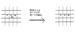
従来技術によるハーフトーン処理では、C、MあるいはYトナードットがK(黒)トナードットの上に印刷されることが多い。これを「オーバープリント(overprinting)」と呼ぶ。カラーのパッチとK(黒)のパッチを重ねて印刷することにより生成された色は、Kのみでの印刷とほとんど区別することができない。このオーバープリントは画質への貢献がほとんどないことが多い。一実施例では、インク使用量を減らすためこのオーバープリントが軽減される。これを「不要色除去(waste color removal)」と呼び、一実施例では、Kドット上にデジタルオーバープリントされたカラードットが、ポストハーフトーン処理工程として除去される。
The choice of halftoning algorithm and parameters affects the amount of ink used. Various techniques are described that require fewer digital dots in the halftone signal (before the physical printing process). Other effects resulting from a decrease in ink usage include, for example, faster paper drying, less ink use of ink jet processing, and environmental impact.
[Overview]
In conventional halftone processing, C, M or Y toner dots are often printed on top of K (black) toner dots. This is called “overprinting”. A color generated by printing a color patch and a K (black) patch on top of each other is almost indistinguishable from printing with K alone. This overprint often has little contribution to image quality. In one embodiment, this overprint is mitigated to reduce ink usage. This is called “waste color removal”, and in one embodiment, the color dots digitally overprinted on the K dots are removed as a post halftone process.
ここで説明されるインク使用量減少技術の一実施例は、ベクトル誤差拡散(VED)を利用したものである。VEDでは4色(CMYK)すべてが同時にハーフトーン処理され、これにより制御対象のカラードットのオーバープリントが可能になる。4色インクカラー印刷のための従来技術によるVEDでは、各入力画素が4色のインクの合成により印刷可能な16色のうちの1つに量子化される。 One embodiment of the ink usage reduction technique described herein utilizes vector error diffusion (VED). In VED, all four colors (CMYK) are halftoned at the same time, which allows overprinting of the color dots to be controlled. In VED according to the prior art for four-color ink printing, each input pixel is quantized to one of 16 printable colors by combining four inks.
一実施例では、不要色除去(WCR)が実行され、Kの上の任意の色がKと同じように現れるという仮定を模倣するようVED誤差計算処理が変更される。 In one embodiment, unwanted color removal (WCR) is performed and the VED error calculation process is modified to mimic the assumption that any color above K appears in the same way as K.

以下の説明では、本発明のさらなる説明を与えるため多くの詳細が与えられる。しかしながら、本発明がこれら特定の詳細を利用することなく実践可能であるということは、当業者には明らかであろう。他の例では、本発明が不明瞭になることを避けるため、周知の構成及び装置は詳細にではなくブロック図の形式で示される。
In the following description, numerous details are given to provide a further description of the invention. However, it will be apparent to those skilled in the art that the present invention may be practiced without the use of these specific details. In other instances, well-known structures and devices are shown in block diagram form, rather than in detail, in order to avoid obscuring the present invention.
以下の詳細な説明の一部は、コンピュータメモリ内のデータビットに対する処理のアルゴリズム及び記号表記に関して与えられる。このようなアルゴリズム的な記述及び表記は、データ処理分野における当業者が他の当業者に研究の本質を最も効果的に伝えるために利用する手段である。アルゴリズムとは、所望の結果を導く自己矛盾のないステップシーケンスであると、ここではそして一般的に考えられるものである。これらのステップは物理的な数量に対する物理的操作を要するものである。必須ではないが、通常これらの数量は格納、転送、合成、比較及び操作可能な電子または磁気信号の形をとる。これらの信号をビット、値、要素、記号、文字、項、数などと呼ぶことは通常の利用のためから便利である。 Some portions of the detailed descriptions that follow are provided in terms of algorithms and symbolic representations of operations on data bits within a computer memory. Such algorithmic descriptions and notations are the means used by those skilled in the data processing arts to most effectively convey the substance of their work to others skilled in the art. An algorithm is here and generally considered to be a self-consistent step sequence that leads to a desired result. These steps are those requiring physical manipulation of physical quantities. Usually, though not necessarily, these quantities take the form of electronic or magnetic signals capable of being stored, transferred, combined, compared, and manipulated. Calling these signals bits, values, elements, symbols, characters, terms, numbers, etc. is convenient for normal use.
しかしながら、これらのすべて及び類似の用語は適当な物理量と関連付けされるべきであり、これらの量に付けられた単なる便宜上のラベルであるということを認識すべきである。また、以下の説明から明らかなように、特に言及されない場合、「処理」、「計算」、「決定」、「表示」などの用語を利用した説明は、コンピュータシステムのレジスタ及びメモリの中の物理(電子)量として表されるデータを、当該コンピュータシステムのレジスタあるいはメモリ、または他の情報格納、送信あるいは表示装置の中の物理量として同様に洗わされる他のデータに処理及び変換するコンピュータシステムまたは同様の電子計算装置のアクション及び処理を言及するものである。 It should be recognized, however, that all of these and similar terms are to be associated with the appropriate physical quantities and are merely convenient labels attached to these quantities. Further, as will be apparent from the following description, unless otherwise stated, explanations using terms such as “processing”, “calculation”, “decision”, “display”, etc. A computer system that processes and converts data represented as (electronic) quantities into other data that is also washed as physical quantities in the registers or memory of the computer system, or other information storage, transmission or display devices, or Reference is made to actions and processing of similar electronic computing devices.
本発明はまた、ここでの処理を実行する装置に関する。本発明による装置は、要求された用途向けに作成されたものであってもよいし、格納されているコンピュータプログラムにより選択的に起動または設定される汎用コンピュータから構成されてもよい。このようなコンピュータプログラムは、以下に限定されるものではないが、例えば、フロッピー(登録商標)ディスク、光ディスク、CD−ROM(Compact Disk-Read Only Memory)、光磁気ディスク、ROM(Read Only Memory)、RAM(Random Access Memory)、EPROM(Erasable Programmable Read Only Memory)、EEPROM(Electronically Erasable and Programmable Read Only Memory)、磁気または光カードを含む任意のタイプのディスク、電子命令の格納に適した任意のタイプのメディアなどの各自がコンピュータシステムバスに接続されているコンピュータ読み出し可能な記憶媒体に格納されてもよい。 The present invention also relates to an apparatus for performing the processing herein. The apparatus according to the present invention may be created for a requested application, or may be constituted by a general-purpose computer that is selectively activated or set by a stored computer program. Such a computer program is not limited to the following, for example, a floppy (registered trademark) disk, an optical disk, a CD-ROM (Compact Disk-Read Only Memory), a magneto-optical disk, a ROM (Read Only Memory). Random Access Memory (RAM), Erasable Programmable Read Only Memory (EPROM), Electronically Erasable and Programmable Read Only Memory (EEPROM), any type of disk including magnetic or optical cards, any type suitable for storing electronic instructions Each of them may be stored in a computer-readable storage medium connected to the computer system bus.
ここで与えられるアルゴリズム及び表示は、本来的には特定のコンピュータや他の装置に関連付けられるものではない。ここでの教示に従ったプログラムにより様々な汎用システムが利用可能であり、また要求される方法ステップを実行により特化した装置の構築が便利であるとわかるかもしれない。これら様々なシステムに対し要求される構成が以下の説明から明らかになるであろう。さらに、本発明は特定のプログラミング言語を参照することによる説明は与えられない。ここで説明される本発明の教示を実現するのに様々なプログラミング言語の利用が可能であるということは理解されるであろう。 The algorithms and displays given here are not inherently associated with a particular computer or other device. Various general purpose systems can be used with the program according to the teachings herein, and it may prove convenient to construct a specialized device by performing the required method steps. The required structure for a variety of these systems will appear from the description below. In addition, the present invention is not described by reference to a particular programming language. It will be appreciated that a variety of programming languages may be used to implement the teachings of the invention described herein.
マシーン読み出し可能な媒体には、マシーン(例えば、コンピュータ)により読み出し可能な形式での情報の格納または送信のための任意の機構が含まれる。マシーン読み出し可能な媒体には、例えば、ROM、RAM、磁気ディスク記憶媒体、光記憶媒体、フラッシュメモリデバイス、電気、光学、音響また他の形式の伝搬信号(例えば、搬送波、赤外線信号、デジタル信号など)などが含まれる。 A machine-readable medium includes any mechanism for storing or transmitting information in a form readable by a machine (eg, a computer). Machine-readable media include, for example, ROM, RAM, magnetic disk storage media, optical storage media, flash memory devices, electrical, optical, acoustic and other forms of propagated signals (eg, carrier waves, infrared signals, digital signals, etc. ) Etc. are included.
以下の説明では、入力(または出力)される色は、4色の要素ベクトル(C,M,Y,K)
として表すことができる。ただし、C、M、Y及びKは100%のインクに対する割合である。従って、(0.8,0.5,0,0)による色は、プリンタに80%のシアンインク、50%のマゼンタインク、0%のイエロー及びブラックインクを印刷することを要求している。または、入力(または出力)される色は、ある範囲内の値として表すこともできる。例えば、8ビットの実施例では、(255,0,0,0)はプリンタに100%のシアンインク、0%のマゼンタ、イエロー及びブラックインクを印刷することを要求するものである。用いられている表現は直接トナーにマッピングされる必要はない。また、ブラックとオレンジやグリーンのような他のカラーを有するベクトルのように、要素数の異なる他の構成要素を有するベクトルが利用されてもよい。例えば、オレンジとグリーンが加えられた6色の要素ベクトル(C,M,Y,K,O,G)が利用されてもよい。
[不要色除去(WCR)]
図1は、インク使用量の減少を実現する一実施例による構成要素のブロック図である。ソースカラー画像100は、印刷対象のカラー画像に対応するカラー画像データを提供する。ソースカラー画像100からのカラー画像データは、典型的には、RGB信号の形式で与えられる。しかしながら、任意のフォーマットによるカラー画像データが利用可能である。
In the following description, the input (or output) color is a four-color element vector (C, M, Y, K)
Can be expressed as However, C, M, Y, and K are ratios with respect to 100% ink. Thus, a color of (0.8, 0.5, 0, 0) requires the printer to print 80% cyan ink, 50% magenta ink, 0% yellow and black ink. Alternatively, the input (or output) color can be expressed as a value within a certain range. For example, in an 8-bit embodiment, (255,0,0,0) requires the printer to print 100% cyan ink, 0% magenta, yellow and black ink. The expression used need not be mapped directly to toner. Further, a vector having another component having a different number of elements, such as a vector having other colors such as black and orange or green, may be used. For example, a six-color element vector (C, M, Y, K, O, G) to which orange and green are added may be used.
[Unnecessary color removal (WCR)]
FIG. 1 is a block diagram of components according to an embodiment that achieves a reduction in ink usage. The
一実施例において、RGBカラーデータは、任意の既知の変換技術を利用して、カラーコンバータ110によりCMYKカラーデータに変換される。一実施例では、カラーコンバータ110はまた、C、M及びYの無色値をKに置き換えるプレハーフトーン処理である下色除去(UCR)を実行する。すなわち、UCRは各入力カラーを新しい入力カラーにマッピングする。UCRは、8ビットのC、M、Y及びKの値のような入力画素に対し実行される。例えば、UCR処理の一実施例では、以下の変換が行われる。すなわち、
Knew=K+min(C,M,Y)
Cnew/Mnew/Ynew=C/M/Y-min(C,M,Y)
である。例えば、ソースとして(100,30,220,0)のCMYKカラー値は、(70,0,190,30)に変換される。この新しいカラー値では、ハーフトーン処理後に要求されるインク使用量をより少なくする傾向がある。
In one embodiment, RGB color data is converted to CMYK color data by
K new = K + min (C, M, Y)
C new / M new / Y new = C / M / Y-min (C, M, Y)
It is. For example, a CMYK color value of (100, 30, 220, 0) as a source is converted to (70, 0, 190, 30). This new color value tends to require less ink usage after halftoning.
ハーフトーン装置120は、CMYKカラーデータを受け取り、修正されたC’M’Y’K’カラーデータを生成する。一実施例では、入力カラーデータは32ビットデータストリーム(C、M、Y及びKの各々に8ビットずつ)であり、出力カラーデータは4ビットデータストリーム(C’、M’、Y’及びK’の各々に8ビットずつ)である。一実施例では、ハーフトーン装置120は誤差拡散ユニットから構成される。あるいは、ハーフトーン装置120はディザユニットから構成されてもよい。ハーフトーン装置120により実行される誤差拡散あるいはディザ処理は、平面単位あるいはベクトル単位で行われてもよい。
ハーフトーン装置120からの出力は、カラーデータの解析により冗長なカラーデータを決定する不要色除去装置130により処理される。例えば、複数のカラードットがブラックドットと空間的に同じ位置に供される場合、出力画像の完全さを失することなく非ブラックドットの消去が可能である。不要色除去装置130は、修正されたカラー画像データを生成し、出力装置140に供給する。出力装置140は、この修正されたカラー画像データに基づき画像を生成する。
The output from the
一実施例では、出力装置140は、上記処理がなされない場合にソース画像の生成に必要となる量よりもより少ないインク使用量で印刷することが可能なプリンタ(インク、レーザ、ワックスなど)やデジタルコピー機のプリンタエンジンである。本明細書を通じ、「インク」という単語はインク、トナーまたはワックスを意味する。また、他の出力装置が利用されてもよい。例えば、後の送信や印刷のために、出力画像データが記憶媒体により格納されてもよい。
In one embodiment, the
以下で詳細に説明されるように、インクマッピング処理では、アンカーがインクにマッピングされる。
[WCR及び誤差拡散]
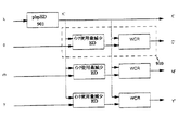
図2Aは、誤差拡散ユニットを備えたWCRデータフロー図である。図2Aを参照するに、誤差拡散ユニット210は、各色平面を独立に処理する平面単位誤差拡散処理を実行する。一実施例では、誤差拡散ユニット201は、CMYKベクトル値に誤差拡散処理を実行する。CMYKの各値は、任意サイズのデータが入力可能であるが、図2のように8ビット値として示される。平面単位誤差拡散処理の結果は不要色除去装置202に供給され、上述のようなインク使用量減少マッピング処理が実行される。この結果には、KドットとC、MあるいはYドットとが重複する画素が含まれる。8ビットのCMYK値の場合では、この結果は、CMYKのカラードットを印刷すべきかを示す各CMYK値のための1ビット値である。不要色除去装置202は、ハーフトーン処理後、ブラックドットとデジタル的に重複するカラードットの除去を実行する。図3は、WCRの一例を示す図である。
As described in detail below, in the ink mapping process, anchors are mapped to ink.
[WCR and error diffusion]
FIG. 2A is a WCR data flow diagram with an error diffusion unit. Referring to FIG. 2A, the error diffusion unit 210 performs a plane unit error diffusion process that processes each color plane independently. In one embodiment,
一実施例では、Kドットに重複するカラードットの100%が除去される。これを100%WCRと呼ぶ。他の実施例では、Kドットに重複するカラードットの一部のみが除去される。これは、セグメンテーションデータ190(オプショナル)のようなセグメンテーションデータがWCRへの入力として利用可能な場合、あるいは近傍のハーフトーンドットに基づく場合であるかもしれない。例えば、一実施例において、Kドットに重複するカラードットが、それと同じ色の他のドットから孤立しない場合に限って、当該カラードットは除去される。重複しているドットすべてを除去しないもう1つの理由は、KCの印刷のようなKにさらなる深みを与えるためである。 In one embodiment, 100% of the color dots that overlap the K dots are removed. This is called 100% WCR. In other embodiments, only some of the color dots that overlap the K dots are removed. This may be the case when segmentation data such as segmentation data 190 (optional) is available as input to WCR, or based on nearby halftone dots. For example, in one embodiment, a color dot is removed only if the color dot that overlaps the K dot is not isolated from other dots of the same color. Another reason for not removing all the overlapping dots is to give K more depth, like KC printing.
セグメンテーションデータの場合、セグメンテーションデータは、例えば、ブラック対非ブラック領域、(例えば、コピー機の)画像対テキストモード、画像の処理領域が関心領域(ROI)にあるかを示すかもしれない。そのようなセグメンテーションデータの取得は既知の方法により実行可能である。 In the case of segmentation data, the segmentation data may indicate, for example, a black versus non-black area, an image versus text mode (eg, a copier), and whether the processing area of the image is in a region of interest (ROI). Such segmentation data acquisition can be performed by known methods.
一実施例では、チェックされたミスレジストレーションにより物理的ブラックドットと重複すると予想されるカラードットが除去されてもよい。
[WCR及びディザ処理]
図2Bは、ディザユニットを備えたWCRデータフロー図である。図2Bを参照するに、ディザユニット203は、各平面に対し独立にディザ処理を実行する。
In one embodiment, color dots that are expected to overlap physical black dots due to checked misregistration may be removed.
[WCR and dither processing]
FIG. 2B is a WCR data flow diagram with a dither unit. Referring to FIG. 2B, the dither unit 203 performs dither processing for each plane independently.
高画質化のため、WCRの実行前にディザ処理を行う1つの方法は、同じサイズのマスクを利用することである。マスクサイズを均一にすることにより、モアレを避けることができ、WCRステップ後良好な画質を実現することができる。例えば、従来技術によると、シアンとマゼンタマスクはブラックマスクから±30度に設定される。しばしば、シアンとマゼンタマスクは同じサイズとなる。 One way to perform dithering before executing WCR to improve image quality is to use masks of the same size. By making the mask size uniform, moire can be avoided and good image quality can be achieved after the WCR step. For example, according to the prior art, the cyan and magenta masks are set to ± 30 degrees from the black mask. Often, the cyan and magenta masks are the same size.
一実施例では、約15度と75度で同じサイズであるマスクが利用される。例えば、そのようなマスクとして、マスクD1、マスクD2及びマスクD3の3つがある。シアンチャンネルはマスクD1により、マゼンタチャンネルはマスクD2により、イエローチャンネルはマスクD3により、ブラックチャンネルはマスクD1、D2またはD3(画像全体で首尾一貫して1つが選ばれる)により、それぞれディザ処理される。 In one embodiment, a mask that is about the same size at about 15 degrees and 75 degrees is utilized. For example, there are three such masks as mask D 1 , mask D 2 and mask D 3 . The cyan channel mask D 1, the magenta channel mask D 2, the yellow channel mask D 3, the black channel mask D 1, D 2 or D 3 (one consistently throughout the image -alanine) , Each is dithered.
同一サイズのマスク生成は、シアンとマゼンタに対し同じサイズのマスクをすでに有する既知のディザマスクセットから開始される。もとのシアンまたはマゼンタマスクの値のシフト、これらの値の反転(正のノイズは負に、負のノイズは正に反転させる)、あるいは他の処理によって、同一サイズの新しいマスクを導出することができる。 Same size mask generation starts with a known dither mask set that already has the same size mask for cyan and magenta. Deriving a new mask of the same size by shifting the values of the original cyan or magenta mask, inverting these values (positive noise is negative, negative noise is positive), or other processing Can do.
一実施例では、シアンチャンネルは(角度15度の)マスクD1により、イエローチャンネルは同一サイズであるが異なる角度(例えば、角度75度)のマスクD2により、ブラックチャンネルはマスクD1またはD2(全体を通じて)により、マゼンタチャンネルはマスクD1を反転したものにより、それぞれディザ処理される。 In one embodiment, the cyan channel is mask D 1 (at an angle of 15 degrees), the yellow channel is mask D 2 of the same size but at a different angle (eg, an angle of 75 degrees), and the black channel is mask D 1 or D. the 2 (throughout), by what the magenta channel obtained by inverting the mask D 1, are respectively dithered.
他の実施例では、シアンチャンネルは(上記と同様)マスクD1により、ブラックチャンネルはマスクD1を反転したものにより、マゼンタチャンネルはマスクD2により、イエローチャンネルはマスクD2を反転させたものにより、それぞれディザ処理される。
[ベクトル誤差拡散(VED)]
一実施例において、ハーフトーン装置120はベクトル誤差拡散ユニットから構成される。ベクトル誤差拡散では、処理のためすべての色平面が同時に利用可能である。誤差拡散ユニット201により実行される平面単位EDと比較して、すべての色平面が利用可能であることにより、量子化(距離メトリックを含む)、誤差計算及び誤差フィルタリング処理の3つの処理ブロックにおいて、より高い柔軟性が可能となる。
In other embodiments, the cyan channel (as above) is mask D 1 , the black channel is the inverted version of mask D 1 , the magenta channel is the mask D 2 , and the yellow channel is the inverted version of mask D 2. Thus, dither processing is performed respectively.
[Vector error diffusion (VED)]
In one embodiment,
図4は、ベクトル誤差拡散処理を実行する誤差拡散ユニットの一実施例のフロー図である。図4に示される各ブロックは、ハードウェア(例えば、回路、専用論理など)、ソフトウェア(例えば、汎用コンピュータシステムや専用マシーンにより実行される)、あるいはそれらを組み合わせたものから構成される処理論理を備える。 FIG. 4 is a flow diagram of one embodiment of an error diffusion unit that performs vector error diffusion processing. Each block shown in FIG. 4 includes processing logic composed of hardware (for example, a circuit, dedicated logic, etc.), software (for example, executed by a general-purpose computer system or a dedicated machine), or a combination thereof. Prepare.
図4を参照するに、CMYK入力画素400が加算ユニット401に入力される。一実施例では、各CMYK値は8ビットである。加算ユニット401はまた、誤差フィルタリングユニット404から入力を受け取り、誤差拡散に関する既知の方法により、前の入力画素に量子化処理を行った結果として生成される誤差値を入力画素400に適用する。
Referring to FIG. 4, the CMYK input pixel 400 is input to the
加算ユニット401の出力が量子化器402に供給され、ベクトル量子化処理が実行され、誤差計算ユニット403に供給される。量子化器402は、既知のカラー量子化テクニックを実行する。量子化器402の出力はC’M’Y’K’インク(またはトナー)410を表す。一実施例では、C’M’Y’K’インク410は1ビット値である。
The output of the
量子化器402の出力はまた、量子化器402の入出力の差を計算する誤差計算ユニット403に供給される。この処理は平面単位で実行されてもよい。この出力される誤差は、誤差値を加算ユニット404に与える誤差フィルタリングユニット404に供給され、CMYK入力画素の他の画素に当該誤差が拡散される。
The output of the
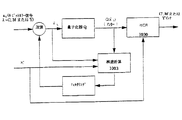
図5は、不要色除去処理に先行する修正されたベクトル誤差拡散処理を実行する誤差拡散ユニットの一実施例のフロー図である。図5に示される各ブロックは、ハードウェア(例えば、回路、専用論理など)、ソフトウェア(例えば、汎用コンピュータシステムや専用マシーンにより実行される)、あるいはそれらを組み合わせたものから構成される処理論理を備える。 FIG. 5 is a flow diagram of one embodiment of an error diffusion unit that performs a modified vector error diffusion process preceding the unwanted color removal process. Each block shown in FIG. 5 includes processing logic composed of hardware (for example, a circuit, dedicated logic, etc.), software (for example, executed by a general-purpose computer system or a dedicated machine), or a combination thereof. Prepare.
図5を参照するに、CMYK入力画素500が加算ユニット501に供給される。一実施例では、各CMYK画素は8ビットである。加算ユニット501はまた、誤差フィルタリングユニット504からの入力を受け取り、誤差拡散に関する既知の方法により、前の入力画素に量子化処理を行った結果として生成される誤差値を入力画素500に適用する。
Referring to FIG. 5, the
加算ユニット501の出力が量子化器502に供給され、ベクトル量子化処理が実行され、誤差計算ユニット503に供給される。量子化器502は、距離メトリックdを利用して、この入力画素をアンカーセットの最近接アンカーに量子化する。アンカーセットは量子化器502に利用可能なカラーセットであり、印刷可能な色数以上であってもよい。一実施例では、アンカーセットは16のベーシックアンカーを含み、これらのアンカーは量子化に利用可能なベーシックインクの組み合わせ(C,M,Y,K,CM,CY,CK,MY,MK,YK,CMY,CMK,CYK,MYK,CMYK, W)である。また距離L1が最も近いインクの決定のため距離メトリックdに対し選ばれる。距離L1は、
The output of the
として表される。一実施例では、アンカーは8ビットの番号である。あるいは、量子化器502は、ユークリッド距離L2あるいは他の既知の距離測度を使って最近接インクを決定するかもしれない。ここで、距離L2は、
Represented as: In one embodiment, the anchor is an 8-bit number. Alternatively, the
として表される。入力画素が量子化されるアンカーは印刷可能な色である必要はない。
Represented as: The anchor on which the input pixel is quantized need not be a printable color.
量子化器502のアンカー出力520は、不要色除去装置(WCR)530に供給される。WCR530は、アンカー出力520を1以上のインクにマッピングする。一実施例では、WCR530は、以下の表2に従ってアンカーをインクにマッピングする。
The
WCR530の出力はC’M’Y’K’インク510である。一実施例では、C’M’Y’K’インク510は1ビット値である。
The output of
量子化器502の出力はまた、量子化器502の入出力の差を計算する誤差計算ユニット503に供給される。この処理は平面単位で実行されてもよい。すなわち、誤差計算ユニット503の出力は、以下の式に従って計算される。
The output of the
誤差=(input(C)-anchor(C),input(M)-anchor(M),input(Y)-anchor(Y),input(K)-anchor(K))
この出力される誤差は、誤差値を加算ユニット502に与える誤差フィルタリングユニット504に供給され、CMYK入力画素500の他の画素に当該誤差が拡散される。誤差フィルタリングユニット504により実行されるこのフィルタリング処理は、平面単位で実行されてもよい。あるいは、誤差フィルタリング処理は、色平面間の誤差を与えてもよい。
Error = (input (C) -anchor (C), input (M) -anchor (M), input (Y) -anchor (Y), input (K) -anchor (K))
This output error is supplied to an
色平面へのベクトル処理に基づく上記実施例に関する変形が可能である。また、上記マッピングはK及び他の値へのものであってもよい。例えば、4色の要素ベクトル(255,255,255,255)はKCにマッピングされてもよい。
[インク使用量減少テクニックの他の実施例]
アンカーは同じ16色C,M,Y,K,CM,CY,CK,MY,MK,YK,CMY,CMK,CYK,MYK,CMYK,Wであってもよいが、他の実施例では異なっていてもよい。他の実施例では、例えば、((0.35C,K),(0.31M,K),(0.31M,0.31Y,K),(0.31C,0.31Y,K),(0.35C,0.35M,K),(.067C,0.67M,0.67Y,K))のような他のアンカーが使用されてもよい。これら追加的なアンカーはKにマッピングされる。このマッピング処理は、量子化器がアンカーを実際の印刷カラーにマッピングした後、実行される。一実施例では、これらすべての追加的アンカーは、印刷出力Kへの量子化後、マッピングされる。
Variations on the above embodiment based on vector processing on the color plane are possible. Also, the mapping may be for K and other values. For example, four color element vectors (255, 255, 255, 255) may be mapped to KC.
[Another Example of Ink Usage Reduction Technique]
The anchor may be the same 16 colors C, M, Y, K, CM, CY, CK, MY, MK, YK, CMY, CMK, CYK, MYK, CMYK, W, but different in other embodiments May be. In other embodiments, for example, ((0.35C, K), (0.31M, K), (0.31M, 0.31Y, K), (0.31C, 0.31Y, K), (0.35C, 0.35M, Other anchors such as K), (.067C, 0.67M, 0.67Y, K)) may be used. These additional anchors are mapped to K. This mapping process is performed after the quantizer maps the anchor to the actual print color. In one embodiment, all these additional anchors are mapped after quantization to the printed output K.
図6は、量子化器602とインクマッピングユニット630以外は図5のフロー図と同様の誤差拡散ユニットの他の実施例のフロー図である。図6に示される各ブロックは、ハードウェア(例えば、回路、専用論理など)、ソフトウェア(例えば、汎用コンピュータシステムや専用マシーンにより実行される)、あるいはそれらを組み合わせたものから構成される処理論理を備える。図6を参照するに、量子化器602は、加算ユニット501からの出力を、例えば、前述の距離L1またはL2の距離メトリックdを利用してアンカーセットの最近接アンカーに量子化する。アンカーセットには、図5に関して説明されたベーシックカラー及びブラックアンカーと共にいくつかの追加的アンカーが含まれる。最近接アンカーはアンカー620として出力される。一実施例では、アンカー620は8ビットアンカーである。
FIG. 6 is a flowchart of another embodiment of the error diffusion unit similar to the flowchart of FIG. 5 except for the
表3は、インクマッピングユニット630により実行されるインクマッピング処理を示す。ここで、表3はまた追加的アンカーを含んでいる。
Table 3 shows the ink mapping process executed by the
[インク使用量減少テクニックのさらなる他の実施例]
他の実施例では、量子化器はすべてのカラー(α,β,γ,255)を含む追加的アンカーを有するかもしれない。ただし、α、β及びγは0から255までの任意の値である。このため、追加的アンカーはKにマッピングされる。図7は、そのような量子化器を備えた誤差拡散ユニットのさらなる他の実施例のフロー図である。図7に示される各ブロックは、ハードウェア(例えば、回路、専用論理など)、ソフトウェア(例えば、汎用コンピュータシステムや専用マシーンにより実行される)、あるいはそれらを組み合わせたものから構成される処理論理を備える。図7を参照するに、量子化器702は、アンカー720を生成し、インクマッピングユニット730がそれを特定のインクにマッピングする。この場合におけるアンカーとインクのマッピングが、以下の表4に示される。
[Still another embodiment of ink usage reduction technique]
In other embodiments, the quantizer may have additional anchors that include all colors (α, β, γ, 255). However, α, β, and γ are arbitrary values from 0 to 255. For this reason, additional anchors are mapped to K. FIG. 7 is a flow diagram of yet another embodiment of an error diffusion unit comprising such a quantizer. Each block shown in FIG. 7 includes processing logic composed of hardware (for example, a circuit, dedicated logic, etc.), software (for example, executed by a general-purpose computer system or a dedicated machine), or a combination thereof. Prepare. Referring to FIG. 7, the
従来技術による平面単位誤差拡散(pbpED)と、すべてのカラー(α,β,γ,255)を含む追加的アンカーを有する量子化器702と任意のカラー(α,β,γ,255)をKにマッピングするマッピング規則に従うインクマッピングユニット730との利用との比較が、以下で説明される。入力及び結果として得られる各ベクトルは、CMYK値の順序集合である。
A prior art planar unit error diffusion (pbpED) and a
[他の修正されたベクトル誤差拡散テクニック]
図8は、不要色除去処理に先行するベクトル誤差拡散処理を実行する誤差拡散ユニットの一実施例のフロー図である。図8に示される各ブロックは、ハードウェア(例えば、回路、専用論理など)、ソフトウェア(例えば、汎用コンピュータシステムや専用マシーンにより実行される)、あるいはそれらを組み合わせたものから構成される処理論理を備える。
[Other modified vector error diffusion techniques]
FIG. 8 is a flowchart of an embodiment of an error diffusion unit that executes a vector error diffusion process preceding the unnecessary color removal process. Each block shown in FIG. 8 includes processing logic composed of hardware (for example, a circuit, dedicated logic, etc.), software (for example, executed by a general-purpose computer system or a dedicated machine), or a combination thereof. Prepare.
図8を参照するに、CMYK入力画素800が加算ユニット801に供給される。一実施例では、各CMYK画素は8ビットである。加算ユニット801はまた、誤差フィルタリングユニット804からの入力を受け取り、誤差拡散に関する既知の方法により、前の入力画素に量子化処理を行った結果として生成される誤差値を入力画素800に適用する。
Referring to FIG. 8, the CMYK input pixel 800 is supplied to the
加算ユニット801の出力が量子化器802に供給され、ベクトル量子化処理が実行され、誤差計算ユニット803に供給される。量子化器802は、一実施例の距離L1を利用して、この入力画素を16のベーシックアンカーの最近接アンカーに量子化する。この量子化は平面単位で実行される。より詳細には、これらのアンカーは、量子化に利用可能な4つのインクのベーシックな組み合わせ(C,M,Y,K,CM,CY,CK,MY,MK,YK,CMY,CMK,CYK,MYK,CMYK,W)である。また距離L1が最も近いインクの決定のため選ばれる。一実施例では、アンカーは8ビットの番号である。あるいは、量子化器802は、ユークリッド距離L2あるいは他の既知の距離測度を使って最近接インクを決定するかもしれない。ここで、入力画素が量子化されるアンカーは印刷可能な色である必要はない。
The output of the
量子化器802のアンカー出力820は、マッピングユニット830に供給される。マッピングユニット830は、アンカー出力820をインクにマッピングする。一実施例では、マッピングユニット830は、以下の表6に従ってアンカーをインクにマッピングする。ここで、255に等しいKを有するすべてのアンカーはKにマッピングされる。
The anchor output 820 of the quantizer 802 is supplied to the
マッピングユニット830の出力はC’M’Y’K’インク810である。一実施例では、C’M’Y’K’インク810は1ビット値である。
The output of the
量子化器802の出力はまた、量子化器802の入出力の差を計算する誤差計算ユニット803に供給される。すなわち、誤差計算ユニット803の出力は、以下に従って計算される。
The output of the quantizer 802 is also supplied to an
量子化器802がK平面に対し255に量子化しない場合、誤差計算は従来技術による平面単位誤差計算である。量子化器802がK平面に対し255に量子化する場合、誤差はC、M及びY平面に対し0となる。K平面に対する誤差は通常通り計算される。
If the quantizer 802 does not quantize to 255 with respect to the K plane, the error calculation is a plane unit error calculation according to the prior art. When the quantizer 802 quantizes to 255 for the K plane, the error is 0 for the C, M, and Y planes. The error for the K plane is calculated as usual.
この出力される誤差は、誤差値を加算ユニット802に与える誤差フィルタリングユニット804に供給され、CMYK入力画素800の他の画素に当該誤差が拡散される。一実施例では、誤差フィルタリングユニット804のフィルタリング処理を実行するフィルタは、Stucki12タップフィルタから構成される(Henry Kang,“Digital Color Halftoning”,SPIE Press,2001を参照されたい)。
The output error is supplied to an
誤差フィルタリングユニット804により実行されるこのフィルタリング処理は、平面単位で実行されてもよい。あるいは、誤差フィルタリング処理は、色平面間の誤差を与えてもよい。
This filtering process performed by the
本発明による誤差拡散テクニックのいくつかの適用事例が以下で与えられる。入力及び結果として得られる各ベクトルは、CMYK値の順序集合である。 Some applications of the error diffusion technique according to the invention are given below. Each input and resulting vector is an ordered set of CMYK values.
[平面単位誤差拡散、WCR及び誤差拡散の数学的記述]
従来の平面単位誤差拡散が数学的に説明され、その後でWCR(平面単位誤差拡散により)と前述の誤差拡散テクニックに対して同様の方程式群が導出される。
[平面単位誤差拡散]
平面単位誤差拡散は、典型的には3つの式、すなわち、前の画素からの誤差を加えることにより入力を修正する式、当該誤差を定義する式及び量子化器を定義する式により説明される(以下の式(1)、(2)及び(3)を参照されたい)。
[Mathematical description of planar unit error diffusion, WCR and error diffusion]
Conventional planar unit error diffusion is mathematically described, and then similar equations are derived for WCR (by planar unit error diffusion) and the aforementioned error diffusion technique.
[Plane unit error diffusion]
Planar unit error diffusion is typically described by three equations: an equation that modifies the input by adding the error from the previous pixel, an equation that defines the error, and an equation that defines the quantizer. (See formulas (1), (2) and (3) below).
x(t)を位置tの入力画像信号とする。従来技術に従って、平面単位誤差拡散はこの信号と継承された誤差とを加え合わせたものとして特徴付けされる以下の2つの方程式により説明される。 Let x (t) be the input image signal at position t. In accordance with the prior art, planar unit error diffusion is described by the following two equations characterized as the sum of this signal and the inherited error.
ここで
here
は誤差拡散出力信号であり、また当該誤差は以下により求められる。
Is an error diffusion output signal, and the error is obtained as follows.
ここでh=(h1,…,hj)は
Where h = (h 1 ,…, h j ) is
を満たす誤差拡散フィルタであり、Q(・)は量子化演算子である。簡単化のため、すべてのtに対して、
Is an error diffusion filter that satisfies Q, and Q (•) is a quantization operator. For simplicity, for all t
であると仮定する。従って、量子化器は以下のように定義される。
Assume that Therefore, the quantizer is defined as follows.
式(1)と(2)を組み合わせることにより、以下の量子化出力が導かれる。より詳細には、式(2)を以下のように書き換える。
Combining equations (1) and (2) leads to the following quantized output: More specifically, equation (2) is rewritten as follows.
これを式(1)に代入することにより、
By substituting this into equation (1),
が得られる。h0=-1として
Is obtained. as h 0 = -1
を定義することにより、式(4)は以下のように表すことができる。
(4) can be expressed as follows.
この拡張されたフィルタ
This expanded filter
はハイパスフィルタであり、この量子化出力はもとの信号と高周波ノイズとして解釈される。
[カラーに拡張された平面単位誤差拡散]
CMYK入力に対し、信号xは4次元ベクトル
x(t)=(xC(t),xM(t),xY(t),xK(t))T
により与えられる。平面単位誤差拡散が各色平面に独立に適用される場合、各量子化出力は式(4)により以下のように表すことができる。
Is a high-pass filter, and this quantized output is interpreted as the original signal and high-frequency noise.
[Plane unit error diffusion extended to color]
For CMYK input, signal x is a four-dimensional vector
x (t) = (x C (t), x M (t), x Y (t), x K (t)) T
Given by. When plane unit error diffusion is applied independently to each color plane, each quantized output can be expressed as follows by equation (4).
100%WCRでは、色平面のあるドットが除去されるのは、ハーフトーン処理されたブラック平面が当該位置にKドットを配置している場合である。従って、平面単位誤差拡散に続く100%WCRでは、まず各色平面が独立に誤差拡散される。次のステップで、K出力が各色出力と以下のようにして合成される。すなわち、K平面の出力がKを印刷する信号を表す「1」である場合、C、M及びYの各色平面の出力はC、MまたはYを印刷しない信号を表す「0」に設定される。従って、KハーフトーンのWCRの出力は変わらないが、C、M及びYハーフトーンに対してWCR出力は以下のようになる。
In 100% WCR, a dot having a color plane is removed when a black plane subjected to halftone processing has K dots arranged at the position. Therefore, in 100% WCR following plane unit error diffusion, first, each color plane is error-diffused independently. In the next step, the K output is combined with each color output as follows. That is, when the output of the K plane is “1” representing a signal for printing K, the output of each color plane of C, M, and Y is set to “0” representing a signal for not printing C, M, or Y. . Therefore, the output of the KCR halftone WCR does not change, but for the C, M and Y halftones, the WCR output is as follows.
QWCR(xλ(t))=(1-Q((xK(t)))・Q(xλ(t)) (6)
ここで、
Q WCR (x λ (t)) = (1-Q ((x K (t))) ・ Q (x λ (t)) (6)
here,
である。
[誤差拡散]
図8のインク使用量減少テクニックでは、誤差は平面単位誤差拡散と異なる方法により計算される。また、図8のインク使用量減少テクニックは、量子化出力に適用されるWCRを含んでいる。図6において誤差計算は以下のように説明されている。
It is.
[Error diffusion]
In the ink usage reduction technique of FIG. 8, the error is calculated by a method different from the plane unit error diffusion. Also, the ink usage reduction technique of FIG. 8 includes WCR applied to the quantized output. In FIG. 6, the error calculation is explained as follows.
式anchor(K)はハーフトーン処理されたK平面のドットであるので、色平面の誤差はすでにハーフトーン処理されたK平面による影響を受ける。ハーフトーン処理されたKがドットを印刷しない場合、誤差は図4に示されたVEDと同じように計算される。量子化ボックスにおいて距離L1が選ばれる場合、VED量子化処理は平面単位誤差拡散量子化処理と同じものとなる。この考察を式(1)及び(2)の数学的表現に変換すると、以下のようになる。
Since the equation anchor (K) is a half-tone K-plane dot, the color plane error is affected by the already half-toned K-plane. If the halftoned K does not print a dot, the error is calculated in the same way as the VED shown in FIG. If the distance L 1 is selected in the quantization box, VED quantization process is the same as the plane unit error diffusion quantization process. Converting this consideration into the mathematical expression of equations (1) and (2) yields:
ハーフトーン処理されたK平面は、K平面の平面単位誤差拡散と同様に、式(5)からの出力 The half-toned K plane is the output from equation (5), as is the plane unit error diffusion of the K plane.
によりモデル化される。
Is modeled by
式(1)及び(2)の記述に従って、3つのカラー平面 Three color planes according to the description of equations (1) and (2)
は、入力信号と継承された誤差とを加え合わせたもの
Is the sum of the input signal and the inherited error
によりモデル化される。また当該誤差は、
Is modeled by The error is
として表される。100%WCRを式(6)を用いて量子化出力
Represented as: 100% WCR quantized output using equation (6)
に適用すると、最終的な2進信号は
When applied to the final binary signal is
により表すことができる。
Can be represented by
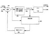
図8のインク使用量減少テクニックの記述では、K平面のハーフトーン出力が利用可能である場合、当該テクニックは各カラー平面に分離可能であるということを示している。この分離処理は図9及び図10に示されるように行われる。図9を参照するに、ユニット901により平面単位誤差拡散処理(pbpED)がブラックカラー平面に対し実行される。ユニット901の出力K’は、その他のカラー平面のための誤差拡散ユニットとWCRユニットに供給される。そのようなペアの1つ910が図10において詳細に示される。図10に示された実施例は、非ブラックカラー平面の何れに対して用いられてもよい。図10を参照するに、ブラック平面に対し実行される平面単位誤差拡散処理の結果、すなわちK’が、誤差計算ユニット1003とWCR1030に供給される。
The description of the ink usage reduction technique in FIG. 8 indicates that if a K-plane halftone output is available, the technique is separable into each color plane. This separation process is performed as shown in FIGS. Referring to FIG. 9,
図10では、まずブラック平面が処理され、その他のカラー平面の処理時にこの結果が利用されているが、まずブラック平面と1つ以上の他のカラー平面が処理され、この処理結果をその他のカラー平面の処理に利用するようにしてもよい。すなわち、カラー平面の第1セットが処理され、(追加的情報を含む)その出力がその他のカラー平面のハーフトーン処理に利用される。この追加的情報とは、前述のセグメンテーションデータであってもよい。あるいは、ブラック以外の1つ以上のカラー平面がまず処理され、その結果がその他のビット平面の処理に利用されてもよい。
[コンピュータシステムの実現例]
一実施例では、前述のテクニックは、例えば、コンピュータシステムやカラープリンタのような電子システムにより実行される命令シーケンスとして実現される。これらの命令は電子装置により記憶及び受信可能である(例えば、ネットワーク接続を介し)。図11は、電子システムの一実施例のブロック図である。
In FIG. 10, the black plane is first processed and this result is used when processing the other color planes. First, the black plane and one or more other color planes are processed, and this processing result is processed for the other color planes. You may make it utilize for the process of a plane. That is, a first set of color planes is processed, and its output (including additional information) is used for halftoning other color planes. This additional information may be the aforementioned segmentation data. Alternatively, one or more color planes other than black may be processed first and the results used for processing other bit planes.
[Example of computer system implementation]
In one embodiment, the techniques described above are implemented as a sequence of instructions that are executed by an electronic system such as, for example, a computer system or a color printer. These instructions can be stored and received by an electronic device (eg, via a network connection). FIG. 11 is a block diagram of one embodiment of an electronic system.
電子システム1100は、情報を通信するためのバス1101または他の通信装置と、情報を処理するためのバス1101に接続されたプロセッサ1102から構成される。1つのプロセッサを備えた電子システム1100が示されているが、電子システム1100は複数のプロセッサ及び/またはコプロセッサを備えていてもよい。電子システム1100は、さらに、バス1101に接続され、情報及びプロセッサ1102により実行される命令を格納するRAM(Random Access Memory)または他の情報記憶装置1104(「メモリ」と呼ばれる)を備える。メモリ1104はまた、プロセッサ1102による命令の実行中、一時的な変数や他の中間情報の格納に利用されてもよい。
The electronic system 1100 includes a
電子システム1100はまた、バス1101に接続され、プロセッサ1102のための静的情報及び命令を格納するROM(Read Only Memory)及び/または他の静的記憶装置1106を備える。情報及び命令を格納するデータ記憶装置1107がバス1101に接続される。磁気ディスクや光ディスクのようなデータ記憶装置1107とそれに対応するドライブが、電子システム1100に接続される。
The electronic system 1100 also includes a read only memory (ROM) and / or other static storage device 1106 that is connected to the
電子システム1100はまた、ユーザに情報を表示する、CRT(Cathode Ray Tube)やLCD(Liquid Crystal Display)のような選択的に配置される表示装置1120にバス1101を介し接続されてもよい。入出力装置1125は、例えば、方向情報やコマンド選択をプロセッサ1102に伝え、表示装置1120上のカーソルの動きを制御するマウス、トラックボールやカーソル方向キーのようなカーソル制御装置を備えていてもよい。電子システム1100は、さらに、ローカルエリアネットワーク(LAN)のようなネットワークへのアクセスを提供するネットワークインタフェース1130を備えている。
The electronic system 1100 may also be connected via a
命令は、例えば、磁気ディスク、ROM集積回路、CD-ROM(Compact Disk-Read Only Memory)やDVD(Digital Versatile Disk)のような記憶装置から、1以上の電子的にアクセス可能なメディアへのアクセスを有線あるいは無線により提供するリモート接続(例えば、ネットワークインタフェース1130を介しネットワーク上に)を介しメモリに与えられる。他の実施例では、ハードウェア的な回路が、ソフトウェア的な命令に代わって、あるいはそれらの組み合わせにより利用されてもよい。すなわち、命令シーケンスの実行は、ハードウェアによる回路とソフトウェアによる命令の特定の組み合わせに限定されるものではない。 The instructions are, for example, access to one or more electronically accessible media from a storage device such as a magnetic disk, ROM integrated circuit, CD-ROM (Compact Disk-Read Only Memory) or DVD (Digital Versatile Disk). Is provided to the memory via a remote connection (for example, on the network via the network interface 1130) that provides wired or wireless. In other embodiments, hardware circuitry may be used in place of software instructions or a combination thereof. That is, the execution of the instruction sequence is not limited to a specific combination of a hardware circuit and software instruction.
以上、本発明の実施例が説明されたが、本発明はこれらに限定されるものではなく、特許請求の範囲に記載された本発明の範囲内で様々な変更及び修正が可能である。 As mentioned above, although the Example of this invention was described, this invention is not limited to these, A various change and correction are possible within the range of this invention described in the claim.
100 ソースカラー画像
110 カラーコンバータ
120 ハーフトーン装置
130、530 不要色除去装置
140 出力装置
210 誤差拡散ユニット
400、500 CMYK入力画素
401、501、 加算ユニット
402、502、602 量子化器
403、503 誤差計算ユニット
404 誤差フィルタリングユニット
410、510 C’M’Y’K’インク
504 誤差フィルタリングユニット
520、620 アンカー出力
630 インクマッピングユニット
1100 電子システム
1101 バス
1102 プロセッサ
1104 メモリ
1107 データ記憶装置
1120 表示装置
1125 入出力装置
1130 ネットワークインタフェース
100
Claims (8)
アンカーに印刷カラーをマッピングするステップと、
を有する方法であって、
前記ベクトル誤差拡散を実行するステップは、
各入力画素値をアンカーセットの最近接アンカーに量子化するステップと、
前記入力画素値と前記アンカーとの差に基づき誤差を計算するステップと、
前記計算された誤差に基づき誤差拡散を実行するステップと、
を有し、
前記アンカーの1以上が前記印刷カラーの1つにマッピングされ、
前記誤差を計算するステップは、
前記アンカーのブラックカラー平面がそれの最大値にない場合、各カラー平面のための前記アンカーを前記入力画素の対応するカラー平面から減じることにより誤差を計算するステップと、
すべての非ブラックカラー平面において前記誤差をすべてゼロとして計算し、前記アンカーのブラックカラー平面がそれの最大値にある場合、前記アンカーのブラックカラー平面値を前記入力画素の前記ブラックカラー平面値から減じるステップと、
を有することを特徴とする方法。 Performing vector error diffusion ; and
Mapping the print color to the anchor ;
A method comprising:
Performing the vector error diffusion comprises:
Quantizing each input pixel value to the closest anchor of the anchor set;
Calculating an error based on a difference between the input pixel value and the anchor;
Performing error diffusion based on the calculated error ;
Have
One or more of the anchors are mapped to one of the print colors ;
Calculating the error comprises:
Calculating an error by subtracting the anchor for each color plane from the corresponding color plane of the input pixel if the black color plane of the anchor is not at its maximum;
Calculate the error as all zeros in all non-black color planes and subtract the anchor's black color plane value from the black color plane value of the input pixel if the anchor's black color plane is at its maximum value Steps,
Method characterized by having a.
アンカーに印刷カラーをマッピングする手段と、
を有する装置であって、
前記ベクトル誤差拡散を実行する手段は、
各入力画素値をアンカーセットの最近接アンカーに量子化する手段と、
前記入力画素値と前記アンカーとの差に基づき誤差を計算する手段と、
前記計算された誤差に基づき誤差拡散を実行する手段と、
を有し、
前記アンカーの1以上が前記印刷カラーの1つにマッピングされ、
前記誤差を計算する手段は、
前記アンカーのブラックカラー平面がそれの最大値にない場合、各カラー平面のための前記アンカーを前記入力画素の対応するカラー平面から減じることにより誤差を計算する手段と、
すべての非ブラックカラー平面において前記誤差をすべてゼロとして計算し、前記アンカーのブラックカラー平面がそれの最大値にある場合、前記アンカーのブラックカラー平面値を前記入力画素の前記ブラックカラー平面値から減じる手段と、
を有することを特徴とする装置。 Means for performing vector error diffusion ;
A means of mapping print colors to anchors ;
A device comprising:
The means for performing the vector error diffusion is:
Means for quantizing each input pixel value to the nearest anchor of the anchor set;
Means for calculating an error based on a difference between the input pixel value and the anchor;
Means for performing error diffusion based on the calculated error ;
Have
One or more of the anchors are mapped to one of the print colors ;
The means for calculating the error is:
Means for calculating an error by subtracting the anchor for each color plane from the corresponding color plane of the input pixel if the black color plane of the anchor is not at its maximum;
Calculate the error as all zeros in all non-black color planes and subtract the anchor's black color plane value from the black color plane value of the input pixel if the anchor's black color plane is at its maximum value Means,
Apparatus characterized by having a.
として定義されるLL defined as 11 距離d(x, y)から構成されることを特徴とする装置。A device characterized by comprising a distance d (x, y).
Applications Claiming Priority (1)
| Application Number | Priority Date | Filing Date | Title |
|---|---|---|---|
| US10/350,121 US7224487B2 (en) | 2003-01-22 | 2003-01-22 | Ink reduction error diffusion |
Publications (3)
| Publication Number | Publication Date |
|---|---|
| JP2004229281A JP2004229281A (en) | 2004-08-12 |
| JP2004229281A5 JP2004229281A5 (en) | 2007-03-01 |
| JP4377249B2 true JP4377249B2 (en) | 2009-12-02 |
Family
ID=32712788
Family Applications (1)
| Application Number | Title | Priority Date | Filing Date |
|---|---|---|---|
| JP2004007224A Expired - Fee Related JP4377249B2 (en) | 2003-01-22 | 2004-01-14 | Ink consumption reduction error diffusion |
Country Status (2)
| Country | Link |
|---|---|
| US (1) | US7224487B2 (en) |
| JP (1) | JP4377249B2 (en) |
Families Citing this family (10)
| Publication number | Priority date | Publication date | Assignee | Title |
|---|---|---|---|---|
| JP4238992B2 (en) * | 2003-12-15 | 2009-03-18 | 富士ゼロックス株式会社 | Color image processing method, color image processing apparatus, color image processing program, and storage medium |
| US7242415B1 (en) | 2004-02-25 | 2007-07-10 | Adobe Systems Incorporated | Processing illustrations using stored information |
| US7623721B1 (en) * | 2005-12-07 | 2009-11-24 | Marvell International Ltd. | High-speed dithering architecture |
| US7777758B2 (en) * | 2006-10-10 | 2010-08-17 | Adobe Systems Incorporated | Automatic trapping of drop shadows |
| JP4671180B2 (en) * | 2007-11-21 | 2011-04-13 | ブラザー工業株式会社 | Printing apparatus and printing system |
| JP4560564B2 (en) * | 2008-03-28 | 2010-10-13 | シャープ株式会社 | Image processing apparatus, image forming apparatus, image processing method, program, and recording medium thereof |
| JP5762153B2 (en) * | 2011-06-07 | 2015-08-12 | 株式会社Pfu | Holding plate |
| US8861038B2 (en) | 2012-01-20 | 2014-10-14 | Oce-Technologies, B.V. | Method for combining direct binary search halftoning with ink saving |
| CN102831292B (en) * | 2012-07-09 | 2015-01-07 | 大连理工大学 | Method for calculating virtual ink diffusion range based on force feedback technology |
| EP3328050A1 (en) * | 2016-11-23 | 2018-05-30 | HP Scitex Ltd | Generating a halftone image |
Family Cites Families (8)
| Publication number | Priority date | Publication date | Assignee | Title |
|---|---|---|---|---|
| US5473446A (en) * | 1992-05-04 | 1995-12-05 | Hewlett-Packard Company | Color digital halftoning using black and secondary color replacement and color vector dithering |
| US5333243A (en) * | 1992-05-04 | 1994-07-26 | Hewlett-Packard Company | Method for forming color images, using a hue-plus-gray color model and error diffusion |
| US5621545A (en) * | 1993-12-08 | 1997-04-15 | Motta; Ricardo J. | Image production using color error diffusion |
| US5402245A (en) * | 1994-01-27 | 1995-03-28 | Hewlett-Packard Company | Bi-level digital color printer system exhibiting improved undercolor removal and error diffusion procedures |
| US5592592A (en) * | 1994-07-01 | 1997-01-07 | Seiko Epson Corporation | Method and apparatus for minimizing artifacts in images produced by error diffusion halftoning utilizing ink reduction processing |
| US6313925B1 (en) * | 1998-06-17 | 2001-11-06 | International Business Machines Corporation | System, method, and program for saving toner/ink in a color printer without sacrificing image quality |
| JP4064023B2 (en) * | 1999-07-28 | 2008-03-19 | 株式会社リコー | Digital image halftone processing method and apparatus, and recording medium on which digital image halftone processing program is recorded |
| US7079289B2 (en) * | 2001-10-01 | 2006-07-18 | Xerox Corporation | Rank-order error diffusion image processing |
-
2003
- 2003-01-22 US US10/350,121 patent/US7224487B2/en not_active Expired - Fee Related
-
2004
- 2004-01-14 JP JP2004007224A patent/JP4377249B2/en not_active Expired - Fee Related
Also Published As
| Publication number | Publication date |
|---|---|
| US7224487B2 (en) | 2007-05-29 |
| JP2004229281A (en) | 2004-08-12 |
| US20040141194A1 (en) | 2004-07-22 |
Similar Documents
| Publication | Publication Date | Title |
|---|---|---|
| US7869096B2 (en) | Table creation method, table creation apparatus, storage medium, and program | |
| JP3638026B2 (en) | Image processing apparatus and image processing method | |
| JP2006333431A (en) | Image processing method, image processing apparatus, image forming apparatus, computer program, and recording medium | |
| US20030025926A1 (en) | Image processing apparatus and image processing method | |
| US5784496A (en) | Error sum method and apparatus for intercolor separation control in a printing system | |
| JP4377249B2 (en) | Ink consumption reduction error diffusion | |
| US20060203280A1 (en) | Image printing apparatus and image printing method | |
| US6304338B1 (en) | Image processing apparatus and method | |
| US8159720B2 (en) | Color error diffusion | |
| JP4518408B2 (en) | Image processing apparatus, method, and program | |
| JP2007053577A (en) | Device and method for image processing | |
| US7002708B2 (en) | Delayed decision dot placement for plane-dependent CMYK error diffusion | |
| JP4067538B2 (en) | Image processing method, image processing apparatus, image forming apparatus, computer program, and recording medium | |
| JPH10229501A (en) | Image processing device and method | |
| JP4499685B2 (en) | Image processing apparatus, image forming apparatus including the same, image processing method, image processing program, and recording medium | |
| JP2000341547A (en) | Device and method for image processing | |
| JP5122507B2 (en) | Image processing apparatus, image forming apparatus, image processing method, program, and recording medium | |
| JP4101741B2 (en) | Image processing apparatus, image forming apparatus, image processing method, image processing program, and recording medium | |
| JP4027300B2 (en) | Image processing method, image processing apparatus, image forming apparatus, computer program, and recording medium | |
| JP2006005907A (en) | Image processing method, image processing apparatus, image forming apparatus, computer program and dummy halftone matrix creating method | |
| JPH11252388A (en) | Color image processing method and its device | |
| JP2005260863A (en) | Image forming device and image forming program | |
| JP5162430B2 (en) | Image processing apparatus and image processing method | |
| JP6140026B2 (en) | Image processing apparatus and method | |
| JP2007055127A (en) | Apparatus and method for processing image |
Legal Events
| Date | Code | Title | Description |
|---|---|---|---|
| A521 | Request for written amendment filed |
Free format text: JAPANESE INTERMEDIATE CODE: A523 Effective date: 20070112 |
|
| A621 | Written request for application examination |
Free format text: JAPANESE INTERMEDIATE CODE: A621 Effective date: 20070112 |
|
| A977 | Report on retrieval |
Free format text: JAPANESE INTERMEDIATE CODE: A971007 Effective date: 20081226 |
|
| A131 | Notification of reasons for refusal |
Free format text: JAPANESE INTERMEDIATE CODE: A131 Effective date: 20090616 |
|
| A521 | Request for written amendment filed |
Free format text: JAPANESE INTERMEDIATE CODE: A523 Effective date: 20090806 |
|
| TRDD | Decision of grant or rejection written | ||
| A01 | Written decision to grant a patent or to grant a registration (utility model) |
Free format text: JAPANESE INTERMEDIATE CODE: A01 Effective date: 20090901 |
|
| A01 | Written decision to grant a patent or to grant a registration (utility model) |
Free format text: JAPANESE INTERMEDIATE CODE: A01 |
|
| A61 | First payment of annual fees (during grant procedure) |
Free format text: JAPANESE INTERMEDIATE CODE: A61 Effective date: 20090910 |
|
| R150 | Certificate of patent or registration of utility model |
Free format text: JAPANESE INTERMEDIATE CODE: R150 |
|
| FPAY | Renewal fee payment (event date is renewal date of database) |
Free format text: PAYMENT UNTIL: 20120918 Year of fee payment: 3 |
|
| FPAY | Renewal fee payment (event date is renewal date of database) |
Free format text: PAYMENT UNTIL: 20130918 Year of fee payment: 4 |
|
| LAPS | Cancellation because of no payment of annual fees |