JP4377020B2 - Method and apparatus for analyzing components in headspace - Google Patents
Method and apparatus for analyzing components in headspace Download PDFInfo
- Publication number
- JP4377020B2 JP4377020B2 JP2000032982A JP2000032982A JP4377020B2 JP 4377020 B2 JP4377020 B2 JP 4377020B2 JP 2000032982 A JP2000032982 A JP 2000032982A JP 2000032982 A JP2000032982 A JP 2000032982A JP 4377020 B2 JP4377020 B2 JP 4377020B2
- Authority
- JP
- Japan
- Prior art keywords
- tube
- coating rod
- shaped tube
- headspace
- gas
- Prior art date
- Legal status (The legal status is an assumption and is not a legal conclusion. Google has not performed a legal analysis and makes no representation as to the accuracy of the status listed.)
- Expired - Fee Related
Links
Images


Description
【0001】
【発明の属する技術分野】
本発明はヘッドスペース成分の分析方法及びその装置に関する。さらに詳しくは、試料を注入した容器内ヘッドスペースの成分を、バランスを維持したまま採取し、次いで分析できるヘッドスペース成分の分析方法及びその装置に関する。
【0002】
【従来の技術】
従来試料を注入した容器内の気相成分、例えば香料とその香気成分を分析する方法としては、いわゆるダイナミック法とスタティック法とが知られている。図6に示すように、ダイナミック法に使用される装置は、通常次のような構成になっている。試料を注入した容器1を所定温度のウォ−タバス2内に設置し、試料中あるいはウォ−タバス2の底部に撹拌子3を設け試料を必要に応じ撹拌できるようにする。図中記号9は撹拌機である。容器1の頂部には水冷管4を介して吸着剤を充填したカラム5を設置する。容器1には、窒素ガスのような不活性ガス注入口6を設ける。不活性ガスを容器中に吹き込み、不活性ガスと共に気相成分を冷却管を経て吸着剤を充填したカラムに通気し、気相成分をカラム中に採取し、採取された気相成分を分析する方法である。不活性ガスの吹き込みにより気相成分を強制的にカラム側に移動させようとするため、試料中の低沸分を本来ヘッドスペース中に存在していた気相成分よりも多く検出しがちであるという欠点をこの方法は有している。
【0003】
スタティック法の中では、例えばガスタイトシリンジで直接ヘッドスペース気相をサンプリングしてガスクロマトグラフに注入してヘッドスペース気相成分を分析する方法、また例えばヘッドスペース気相中に吸着剤を塗布したファイバを曝して気相成分を吸着剤に吸着し、ガスクロマトグラフに注入して気相成分を分析するソリッドフェーズミクロエキストラクション法(SPME法;特表平5−506715号公報)がよく知られている。このSPME法に使用される装置は、図7に示すように通常次のような構成になっている。ウォ−タバス2内に設置された試料を注入した容器1内に吸着剤を塗布したファイバ7をヘッドスペース内に挿入し、気相成分を吸着させる。このファイバ7はシリンジの中空ニードル(図示せず)内に収納されるようになっている。吸着後、ファイバをニードル内に収納し、ニードルをガスクロマトグラフに連結して吸着された成分を分析する方法である。この方法では、気相成分をそのままのバランスを維持して測定することが可能である。しかしファイバがニードル内に収納できるようにしているため、ファイバを細いものとせざるを得ない。このため、吸着量が少なく、このため多種類にわたる香気成分の分析には不十分な量となることが多い。
【0004】
【発明が解決しようとする課題】
本発明は、上記の問題を解決し、試料を注入した容器中ヘッドスペースの気相成分を、そのバランスをくずすことなく、分析できる方法及びその装置の提供を目的とする。
【0005】
【課題を解決するための手段】
本発明は、下記工程a〜dからなることを特徴とするヘッドスペース成分の分析方法を提供する。
【0006】
a. 試料を注入した密閉容器のヘッドスペースに吸着剤を塗布したコーティング棒を装入する工程、
b. ヘッドスペース中の成分を吸着したコーティング棒を密閉容器から取り出し、少なくとも上部側に加熱手段を備えたU字管の一端から該U字管に装入する工程、
c. コーティング棒を装着したU字管の少なくとも下部部分を冷媒中に浸漬した後、U字管を加熱し、コーティング棒に吸着された成分を脱着し、脱着した成分をU字管の底部に蓄積する工程、
d. 冷媒中から取り出したU字管の他端をガスクロマトグラフの試料注入口に連結し、不活性ガスの送入により脱着した成分を分析する工程。
【0007】
本発明はさらに、吸着剤層を設けたコーティング棒と、該コーティング棒をU字管の一方の管中を滑動自在であるように装着するための支持管と、支持管と該支持管を取付るU字管の一端との間にU字管内部を支持管に対し密閉自在とする開閉部材と、U字管の他端にガスクロマトグラフ連結部材とを備えたことを特徴とするヘッドスペース成分の分析装置を提供する。
【0008】
【発明の実施の形態】
本発明を以下図面に基づいて説明する。図1は、吸着剤層12を設けたコーティング棒11を示す。コーティング棒はガラス棒、ステンレス棒のような金属棒のみならず、ファイバを束ねたものであってもよい。例えば溶融シリカファイバ、グラファイトファイバ、固体ポリマー材料から作られたファイバ、金属材料から作られたファイバ等から形成される。吸着剤層に使用される吸着剤としては、気相成分に応じ適宜の吸着剤が選択使用される。
【0009】
図2は、コーティング棒の吸着剤層に気相成分を吸着させるときの装置の一例を示す。ウォ−タバス2内に設置した、試料を注入した容器1のヘッドスペースにコーティング棒11を挿入し、気相成分を吸着剤層に吸着させる。試料は撹拌子3により必要に応じ撹拌してもよい。気相成分を吸着したコーティング棒11を、U字管に装入する。
【0010】
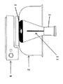
U字管を含む本発明の分析装置を図3及び図4に示す。U字管15には吸着された気相成分を脱着するための加熱手段16が設けられている。加熱手段16は、ニクロム線を適宜の間隔でU字管に巻き付けたものであってもよい。U字管のコーティング棒11装入側の端部には、U字管内部を外気と遮断し、かつコーティング棒を滑動自在とすることができる開閉部材14を介してコーティング棒11の支持管13が設置されている。開閉部材14としては所謂ボールバルブを使用するのが好ましい。ボールバルブ14を開いた状態にしておいて、支持管13、U字管15内にコーティング棒11を装入する。コーティング棒11の頂部には、ハンドル17を設け、コーティング棒11の装入完了時に支持管13の内部を外気と遮断できるようにするのが好ましい。U字管15の開閉部材14近傍に不活性ガス注入口18を設ける。U字管15の他端部側には、U字管15内部と連通したガスクロマトグラフ連結部材19を設ける。
【0011】
コーティング棒11を装入したU字管15の下部を冷媒槽20内に設置する。冷媒としては、液体窒素、液体酸素等気相成分に応じ適宜の冷媒を選択使用する。冷媒槽20内に設置後、加熱手段16により加熱し、気相成分を吸着剤槽から脱着させる。脱着した気相成分は、冷媒により冷却され、U字管底部に蓄積する。吸着剤槽からの脱着促進、U字管底部側への移動促進のために、不活性ガス注入口18から不活性ガスを注入してもよい。不活性ガスとしては、アルゴンガス、ヘリウムガス、窒素ガス等適宜のガスを選択使用する。
【0012】
気相成分の脱着後、図4に示すように、コーティング棒11を開閉部材14よりも上部に引き上げ、開閉部材例えばボールバルブを閉状態とし、ついで冷媒槽20から取り出す。U字管15の他端に設けたガスクロマトグラフ連結部材19をガスクロマトグラフに連結し、不活性ガス注入口20から不活性ガスを注入して、気相成分をガスクロマトグラフに送入し、気相成分を分析する。
【0013】
【実施例】
以下実施例に基づいて本発明をより詳細に説明する。
【0014】
実施例1
粉砕した焙煎コーヒー豆(ブラジル)を使用して、図2に示した方法でヘッドスペース中の気相成分(香気)を捕集し、さらに吸着した成分を図3及び図4に示した装置を用いて吸着成分を脱着した後、ガスクロマトグラフにより分析した。分析条件は以下に示した。
気相成分捕集条件
試料量: 5.0g
外温: 30℃
捕集時間: 30分間
吸着剤: テナックス系
脱着条件
コーティング棒11を図3に示すようにU字管に装着し、ボールバルブ14により支持管13側とU字管側とを遮断した後、ヘリウムガスを送りながらヒーターを220℃に加熱し、コーティング棒に吸着された気相成分を冷媒槽で冷却されたU字管底部に蓄積した。その後、コーティング棒11を図4に示す位置に移動し、同じくボールバルブ14により支持管側とU字管側とを遮断した後、冷媒槽20を外し、ついでヘリウムガスを送って気相成分をガスクロマトグラフに注入し分析した。
ガスクロマトグラフ条件
ガスクロマトグラフ:Shimadzu GC-14A(島津製作所(社)製)
カラム: TC-WAX 0.25MMI.D.×60m
カラム温度: 70℃〜220℃(毎分3℃昇温)
キャリアガス: 窒素
検出器: FID
【0015】
比較例1
粉砕した焙煎コーヒー豆(ブラジル)を使用し、図6に示すダイナミック法でヘッドスペース中の気相成分を捕集し、吸着成分をガスクロマトグラフにより分析した。捕集中水冷管には通水しなかった。分析条件を以下に示す。
気相成分捕集条件
試料量: 1.0g
外温: 30℃
窒素ガス流量: 50ml/min.
吸着時間: 1分間
吸着剤: テナックスTA
ガスクロマトグラフ条件
実施例1と同じ
実施例1と比較例1とで分析したガスクロマトグラムを図5に示した。本発明の方法、装置により分析した焙煎コーヒー豆の香気成分は、比較例1の方法に比して中、高沸点成分まで分析できていた。
【0016】
【発明の効果】
本発明によれば、ヘッドスペース中の気相成分をバランスを崩すことなく、採集可能であり、かつ気相成分の分析に十分な量を採集できる。
【図面の簡単な説明】
【図1】本発明のコーティング棒を示す図面である。
【図2】本発明の気相成分吸着を示す説明図である。
【図3】コーティング棒吸着成分の脱着機構を示す説明図である。
【図4】脱着成分のガスクロマトグラフ送入機構を示す説明図である。
【図5】実施例と比較例のガスクロマトグラフ分析結果を示す図面である。
【図6】ダイナミック法による気相成分の吸着機構を示す説明図である。
【図7】スタティック法による気相成分の吸着機構を示す説明図である。
【符号の説明】
1 容器
11 コーティング棒
12 吸着剤層
13 支持管
14 開閉部材
15 U字管
16 加熱手段
17 ハンドル
18 不活性ガス注入口
19 ガスクロマトグラフ連結口
20 冷媒槽[0001]
BACKGROUND OF THE INVENTION
The present invention relates to a headspace component analysis method and apparatus. More specifically, the present invention relates to an analysis method and apparatus for a headspace component, in which a component of a headspace in a container into which a sample is injected can be collected while maintaining a balance and then analyzed.
[0002]
[Prior art]
Conventionally, as a method for analyzing a gas phase component in a container into which a sample is injected, for example, a perfume and its aroma component, so-called dynamic method and static method are known. As shown in FIG. 6, the apparatus used for the dynamic method is usually configured as follows. The
[0003]
In the static method, for example, a headspace gas phase is directly sampled with a gas tight syringe and injected into a gas chromatograph to analyze a headspace gas phase component, for example, a fiber in which an adsorbent is coated in the headspace gas phase. A solid phase micro-extraction method (SPME method; Japanese Patent Publication No. 5-506715) is well known in which a gas phase component is adsorbed by an adsorbent and injected into a gas chromatograph to analyze the gas phase component. . As shown in FIG. 7, the apparatus used for this SPME method usually has the following configuration. A
[0004]
[Problems to be solved by the invention]
An object of the present invention is to solve the above problems and to provide a method and an apparatus for analyzing a gas phase component in a head space in a container into which a sample is injected without losing the balance.
[0005]
[Means for Solving the Problems]
The present invention provides a method for analyzing a headspace component, which comprises the following steps a to d.
[0006]
a. loading a coating rod coated with an adsorbent into the headspace of a sealed container into which the sample has been injected;
b. A step of taking out the coating rod that has adsorbed the components in the head space from the sealed container and inserting it into the U-shaped tube from one end of the U-shaped tube equipped with heating means at least on the upper side,
c. After immersing at least the lower part of the U-tube with the coating rod in the refrigerant, heat the U-tube to desorb the components adsorbed on the coating rod, and place the desorbed components on the bottom of the U-tube. The process of accumulating,
d. A step of connecting the other end of the U-shaped tube taken out from the refrigerant to the sample inlet of the gas chromatograph and analyzing the components desorbed by the introduction of inert gas.
[0007]
The present invention further includes a coating rod provided with an adsorbent layer, a support tube for mounting the coating rod so as to be slidable in one of the U-shaped tubes, a support tube, and the support tube attached thereto. A headspace component comprising: an opening / closing member that allows the inside of the U-tube to be sealed with respect to the support tube between one end of the U-tube and a gas chromatograph connecting member at the other end of the U-tube An analysis apparatus is provided.
[0008]
DETAILED DESCRIPTION OF THE INVENTION
The present invention will be described below with reference to the drawings. FIG. 1 shows a coating rod 11 provided with an
[0009]
FIG. 2 shows an example of an apparatus for adsorbing a gas phase component on the adsorbent layer of the coating rod. The coating rod 11 is inserted into the head space of the
[0010]
The analyzer of the present invention including a U-shaped tube is shown in FIGS. The U-shaped
[0011]
The lower part of the
[0012]
After the desorption of the gas phase component, as shown in FIG. 4, the coating rod 11 is lifted above the opening / closing
[0013]
【Example】
Hereinafter, the present invention will be described in more detail based on examples.
[0014]
Example 1
Using the pulverized roasted coffee beans (Brazil), the gas phase component (fragrance) in the head space is collected by the method shown in FIG. 2, and the adsorbed components are shown in FIG. 3 and FIG. The adsorbed components were desorbed using and analyzed by gas chromatography. The analysis conditions are shown below.
Gas phase component collection condition Sample amount: 5.0 g
External temperature: 30 ° C
Collection time: 30 minutes Adsorbent: Tenax system desorption condition As shown in FIG. 3, the coating rod 11 is attached to the U-shaped tube, and the support tube 13 side and the U-shaped tube side are blocked by the
Gas chromatograph conditions Gas chromatograph: Shimadzu GC-14A (manufactured by Shimadzu Corporation)
Column: TC-WAX 0.25MMI.D. × 60m
Column temperature: 70 ° C. to 220 ° C. (temperature rise of 3 ° C. per minute)
Carrier gas: Nitrogen detector: FID
[0015]
Comparative Example 1
Using ground roasted coffee beans (Brazil), the gas phase components in the head space were collected by the dynamic method shown in FIG. 6 , and the adsorbed components were analyzed by gas chromatography. Water was not passed through the catching water condenser. The analysis conditions are shown below.
Gas phase component collection conditions Sample amount: 1.0 g
External temperature: 30 ° C
Nitrogen gas flow rate: 50ml / min.
Adsorption time: 1 minute Adsorbent: Tenax TA
Gas Chromatograph Conditions The same gas chromatogram analyzed in Example 1 and Comparative Example 1 as in Example 1 is shown in FIG. Compared with the method of Comparative Example 1, the aromatic component of roasted coffee beans analyzed by the method and apparatus of the present invention could be analyzed up to a medium-high boiling point component.
[0016]
【The invention's effect】
According to the present invention, the gas phase components in the head space can be collected without breaking the balance, and an amount sufficient for the analysis of the gas phase components can be collected.
[Brief description of the drawings]
FIG. 1 shows a coating rod according to the present invention.
FIG. 2 is an explanatory view showing gas phase component adsorption according to the present invention.
FIG. 3 is an explanatory view showing a desorption mechanism for a coating rod adsorbing component.
FIG. 4 is an explanatory view showing a gas chromatograph feeding mechanism of a desorption component.
FIG. 5 is a drawing showing the results of gas chromatographic analysis in Examples and Comparative Examples.
FIG. 6 is an explanatory view showing an adsorption mechanism of a gas phase component by a dynamic method.
FIG. 7 is an explanatory view showing an adsorption mechanism of a gas phase component by a static method.
[Explanation of symbols]
DESCRIPTION OF
Claims (4)
a. 試料を注入した密閉容器のヘッドスペースに吸着剤を塗布したコーティング棒を装入する工程、
b. ヘッドスペース中の成分を吸着したコーティング棒を密閉容器から取り出し、少なくとも上部側に加熱手段を備えたU字管の一端から該U字管に装入する工程、
c. コーティング棒を装着したU字管の少なくとも下部部分を冷媒中に浸漬した後、U字管を加熱し、コーティング棒に吸着された成分を脱着し、脱着した成分をU字管の底部に蓄積する工程、
d. 冷媒中から取り出したU字管の他端側をガスクロマトグラフの試料注入口に連結し、不活性ガスの送入により脱着した成分を分析する工程。A headspace component analysis method comprising the following steps a to d:
a. loading a coating rod coated with an adsorbent into the headspace of a sealed container into which the sample has been injected;
b. A step of taking out the coating rod that has adsorbed the components in the head space from the sealed container and inserting it into the U-shaped tube from one end of the U-shaped tube equipped with heating means at least on the upper side,
c. After immersing at least the lower part of the U-tube with the coating rod in the refrigerant, heat the U-tube to desorb the components adsorbed on the coating rod, and place the desorbed components on the bottom of the U-tube. The process of accumulating,
d. The step of connecting the other end of the U-shaped tube taken out from the refrigerant to the sample inlet of the gas chromatograph and analyzing the components desorbed by the introduction of inert gas.
Priority Applications (1)
| Application Number | Priority Date | Filing Date | Title |
|---|---|---|---|
| JP2000032982A JP4377020B2 (en) | 2000-02-10 | 2000-02-10 | Method and apparatus for analyzing components in headspace |
Applications Claiming Priority (1)
| Application Number | Priority Date | Filing Date | Title |
|---|---|---|---|
| JP2000032982A JP4377020B2 (en) | 2000-02-10 | 2000-02-10 | Method and apparatus for analyzing components in headspace |
Publications (3)
| Publication Number | Publication Date |
|---|---|
| JP2001221785A JP2001221785A (en) | 2001-08-17 |
| JP2001221785A5 JP2001221785A5 (en) | 2007-03-01 |
| JP4377020B2 true JP4377020B2 (en) | 2009-12-02 |
Family
ID=18557528
Family Applications (1)
| Application Number | Title | Priority Date | Filing Date |
|---|---|---|---|
| JP2000032982A Expired - Fee Related JP4377020B2 (en) | 2000-02-10 | 2000-02-10 | Method and apparatus for analyzing components in headspace |
Country Status (1)
| Country | Link |
|---|---|
| JP (1) | JP4377020B2 (en) |
Families Citing this family (5)
| Publication number | Priority date | Publication date | Assignee | Title |
|---|---|---|---|---|
| JP4131837B2 (en) * | 2003-06-02 | 2008-08-13 | 長谷川香料株式会社 | Aroma component adsorbent |
| JP6198408B2 (en) * | 2012-04-02 | 2017-09-20 | 株式会社日立ハイテクノロジーズ | Method for analyzing volatile substances in sample liquid |
| JP6621654B2 (en) * | 2015-11-27 | 2019-12-18 | アサヒ飲料株式会社 | Aroma analysis method for coffee |
| JP7109889B2 (en) * | 2016-08-04 | 2022-08-01 | 三栄源エフ・エフ・アイ株式会社 | Collection method of aroma components |
| CN112058016B (en) * | 2020-09-17 | 2022-08-05 | 乔治洛德方法研究和开发液化空气有限公司 | Method for removing adsorbent media from an adsorption vessel |
Family Cites Families (5)
| Publication number | Priority date | Publication date | Assignee | Title |
|---|---|---|---|---|
| JPH0291564A (en) * | 1988-09-29 | 1990-03-30 | Hitachi Ltd | Head space sampler |
| GB9007356D0 (en) * | 1990-04-02 | 1990-05-30 | Pawliszyn Janusz B | Micro solid phase extraction with fused silica optical fibres |
| JPH08327615A (en) * | 1995-03-24 | 1996-12-13 | Shimadzu Corp | Sampler |
| JPH10325832A (en) * | 1997-05-23 | 1998-12-08 | Sumitomo Metal Mining Co Ltd | Method and apparatus for measuring volatile component in soil |
| AU1018199A (en) * | 1997-11-15 | 1999-06-07 | Brechbuhler Ag | Method and equipment for measuring global volatile substances |
-
2000
- 2000-02-10 JP JP2000032982A patent/JP4377020B2/en not_active Expired - Fee Related
Also Published As
| Publication number | Publication date |
|---|---|
| JP2001221785A (en) | 2001-08-17 |
Similar Documents
| Publication | Publication Date | Title |
|---|---|---|
| CN109196353A (en) | Vacuum aided sample extraction device and method | |
| CA2493449C (en) | Analyte pre-concentrator for gas chromatography | |
| JP5148933B2 (en) | Sample concentration method and apparatus | |
| JP2021501313A (en) | Sample pre-concentration system and method for use in gas chromatography | |
| JP4377020B2 (en) | Method and apparatus for analyzing components in headspace | |
| JP2021501880A (en) | High-speed quasi-ambient temperature multicapillary column preconcentration system for volatile chemical analysis by gas chromatography | |
| US20170303900A1 (en) | Breath condensate and saliva analysis using oral rinse | |
| JP2012132781A (en) | Analytical method using gas chromatography and analyzer using gas chromatography | |
| WO2018013946A1 (en) | Breath condensate and saliva analysis using oral rinse | |
| JP2596882B2 (en) | Thermal analyzer | |
| JP4131837B2 (en) | Aroma component adsorbent | |
| JP5542157B2 (en) | Apparatus and method for the preparation of samples for gas chromatography | |
| US20130000485A1 (en) | Flow Control System, Device and Method for Thermal Desorption | |
| US7047661B2 (en) | Solid phase microextraction fiber cleaning and conditioning apparatus and method | |
| JP4064349B2 (en) | Transfer of sample from solid support into liquid | |
| JP2000234990A (en) | Device for analyzing trace volatile gas constituent | |
| US20220381766A1 (en) | System and method of gas sampling for trace-level analysis of chemical compounds | |
| JP3567154B2 (en) | Sampler | |
| CN109342618A (en) | A kind of automation pre-processing device for VOCs in gas chromatographic detection material | |
| US20030172718A1 (en) | Gaseous sample injection apparatus for gas chromatography | |
| JP3492248B2 (en) | Method for measuring trace helium in metals | |
| Ott et al. | Automated procedure for headspace analysis by glass capillary gas chromatography | |
| JP3299562B2 (en) | Trace organic compound analysis method and device | |
| JP3367293B2 (en) | Gas chromatograph sample introduction method | |
| KR101721387B1 (en) | Gas extraction apparatus and gas analysis system comprising the same |
Legal Events
| Date | Code | Title | Description |
|---|---|---|---|
| A521 | Written amendment |
Free format text: JAPANESE INTERMEDIATE CODE: A523 Effective date: 20070115 |
|
| A621 | Written request for application examination |
Free format text: JAPANESE INTERMEDIATE CODE: A621 Effective date: 20070115 |
|
| A977 | Report on retrieval |
Free format text: JAPANESE INTERMEDIATE CODE: A971007 Effective date: 20090508 |
|
| A131 | Notification of reasons for refusal |
Free format text: JAPANESE INTERMEDIATE CODE: A131 Effective date: 20090616 |
|
| A521 | Written amendment |
Free format text: JAPANESE INTERMEDIATE CODE: A523 Effective date: 20090805 |
|
| TRDD | Decision of grant or rejection written | ||
| A01 | Written decision to grant a patent or to grant a registration (utility model) |
Free format text: JAPANESE INTERMEDIATE CODE: A01 Effective date: 20090908 |
|
| A01 | Written decision to grant a patent or to grant a registration (utility model) |
Free format text: JAPANESE INTERMEDIATE CODE: A01 |
|
| A61 | First payment of annual fees (during grant procedure) |
Free format text: JAPANESE INTERMEDIATE CODE: A61 Effective date: 20090910 |
|
| R150 | Certificate of patent or registration of utility model |
Free format text: JAPANESE INTERMEDIATE CODE: R150 Ref document number: 4377020 Country of ref document: JP Free format text: JAPANESE INTERMEDIATE CODE: R150 |
|
| FPAY | Renewal fee payment (event date is renewal date of database) |
Free format text: PAYMENT UNTIL: 20120918 Year of fee payment: 3 |
|
| FPAY | Renewal fee payment (event date is renewal date of database) |
Free format text: PAYMENT UNTIL: 20130918 Year of fee payment: 4 |
|
| FPAY | Renewal fee payment (event date is renewal date of database) |
Free format text: PAYMENT UNTIL: 20130918 Year of fee payment: 4 |
|
| LAPS | Cancellation because of no payment of annual fees |