JP4375401B2 - Inkjet recording device - Google Patents
Inkjet recording device Download PDFInfo
- Publication number
- JP4375401B2 JP4375401B2 JP2006531373A JP2006531373A JP4375401B2 JP 4375401 B2 JP4375401 B2 JP 4375401B2 JP 2006531373 A JP2006531373 A JP 2006531373A JP 2006531373 A JP2006531373 A JP 2006531373A JP 4375401 B2 JP4375401 B2 JP 4375401B2
- Authority
- JP
- Japan
- Prior art keywords
- recording
- ink
- image
- per color
- control unit
- Prior art date
- Legal status (The legal status is an assumption and is not a legal conclusion. Google has not performed a legal analysis and makes no representation as to the accuracy of the status listed.)
- Active
Links
Images


Classifications
-
- B—PERFORMING OPERATIONS; TRANSPORTING
- B41—PRINTING; LINING MACHINES; TYPEWRITERS; STAMPS
- B41J—TYPEWRITERS; SELECTIVE PRINTING MECHANISMS, i.e. MECHANISMS PRINTING OTHERWISE THAN FROM A FORME; CORRECTION OF TYPOGRAPHICAL ERRORS
- B41J11/00—Devices or arrangements of selective printing mechanisms, e.g. ink-jet printers or thermal printers, for supporting or handling copy material in sheet or web form
- B41J11/0015—Devices or arrangements of selective printing mechanisms, e.g. ink-jet printers or thermal printers, for supporting or handling copy material in sheet or web form for treating before, during or after printing or for uniform coating or laminating the copy material before or after printing
- B41J11/002—Curing or drying the ink on the copy materials, e.g. by heating or irradiating
- B41J11/0021—Curing or drying the ink on the copy materials, e.g. by heating or irradiating using irradiation
- B41J11/00214—Curing or drying the ink on the copy materials, e.g. by heating or irradiating using irradiation using UV radiation
-
- B—PERFORMING OPERATIONS; TRANSPORTING
- B41—PRINTING; LINING MACHINES; TYPEWRITERS; STAMPS
- B41J—TYPEWRITERS; SELECTIVE PRINTING MECHANISMS, i.e. MECHANISMS PRINTING OTHERWISE THAN FROM A FORME; CORRECTION OF TYPOGRAPHICAL ERRORS
- B41J11/00—Devices or arrangements of selective printing mechanisms, e.g. ink-jet printers or thermal printers, for supporting or handling copy material in sheet or web form
- B41J11/0015—Devices or arrangements of selective printing mechanisms, e.g. ink-jet printers or thermal printers, for supporting or handling copy material in sheet or web form for treating before, during or after printing or for uniform coating or laminating the copy material before or after printing
- B41J11/002—Curing or drying the ink on the copy materials, e.g. by heating or irradiating
- B41J11/0021—Curing or drying the ink on the copy materials, e.g. by heating or irradiating using irradiation
- B41J11/00216—Curing or drying the ink on the copy materials, e.g. by heating or irradiating using irradiation using infrared [IR] radiation or microwaves
Description
本発明は、インクジェット記録装置に係り、特に、光を照射することによって硬化する光硬化型のインクを用いて画像記録を行うインクジェット記録装置に関するものである。 The present invention relates to an ink jet recording apparatus, and more particularly to an ink jet recording apparatus that performs image recording using a photocurable ink that cures when irradiated with light.
一般に、少量多品種の需要に対して臨機応変に対応できるインクジェット記録装置として、従来よりインクジェット方式の記録装置(以下「インクジェット記録装置」と称する。)が知られている。インクジェット記録装置は、記録ヘッドの記録媒体に対向する面に設けられたノズルからインクを吐出して記録媒体上に着弾、定着させることにより記録媒体に画像を記録するものであり、従来のグラビア印刷方式やフレキソ印刷方式による画像記録手段と異なって製版工程を必要としないため少量の需要にも簡易かつ迅速に対応することができるという特徴を有している。また、騒音が少なく多色のインクを用いることによってカラーでの画像記録も容易に行うことができるという長所がある。 In general, an ink jet recording apparatus (hereinafter, referred to as “ink jet recording apparatus”) is known as an ink jet recording apparatus that can flexibly meet the demand for a small variety of products. An ink jet recording apparatus records an image on a recording medium by ejecting ink from a nozzle provided on the surface of the recording head facing the recording medium, and landing and fixing on the recording medium. Conventional gravure printing Unlike the image recording means based on the system or flexographic printing system, it does not require a plate making process, and therefore can easily and quickly respond to a small amount of demand. In addition, there is an advantage that color image recording can be easily performed by using multi-color ink with less noise.
さらに近年は、様々な記録媒体に対応可能なインクジェット記録装置として、光硬化型インクを用いたインクジェット記録装置が知られている(例えば、特許文献1参照)。これは、紫外線等の光に対して所定の感度を有する光開始剤が含有された光硬化型インクを用い、記録媒体上に着弾したインクに光を照射することで、インクを硬化させ記録媒体上に定着させるものである。このような光硬化型インクを用いたインクジェット記録装置は、インク着弾後、光を照射することによりインクが瞬時に硬化するため、記録媒体へのインクの浸透や滲みが少なく、普通紙はもとより、インク受容層を持たずインク吸収性の全くないプラスチックや金属等の記録媒体に対しても画像記録を行うことが可能である。 Further, in recent years, an ink jet recording apparatus using a photocurable ink is known as an ink jet recording apparatus compatible with various recording media (see, for example, Patent Document 1). This is because a photocurable ink containing a photoinitiator having a predetermined sensitivity to light such as ultraviolet rays is used, and the ink is cured by irradiating the ink landed on the recording medium with light. It is to fix on top. An ink jet recording apparatus using such a photocurable ink, after ink landing, the ink is cured instantaneously by irradiating light, so that there is little ink penetration or bleeding into the recording medium, not only plain paper, It is possible to record an image on a recording medium such as plastic or metal that does not have an ink receiving layer and has no ink absorbability.
しかし、一般に、水性インクや油性インクを用いてインク受容層をもつ記録媒体を用いて画像記録を行う場合にはインクの大部分が記録媒体に吸収されるのに対して、光硬化型インクを用いてインク受容層を持たない記録媒体に対して画像記録を行う場合には、インクは光が照射されると同時に硬化定着し記録媒体に吸収されないため、記録媒体表面にインクが残留して、インク着弾部分が隆起した状態でインクが硬化する。 However, in general, when image recording is performed using a recording medium having an ink receiving layer using water-based ink or oil-based ink, most of the ink is absorbed by the recording medium, whereas photocurable ink is used. When recording an image on a recording medium having no ink-receiving layer, the ink is cured and fixed at the same time as light is irradiated and is not absorbed by the recording medium, so that the ink remains on the surface of the recording medium, The ink is cured with the ink landing portion raised.
このため、記録画像の表面にざらつきや凹凸が生じることによって目視した場合に光沢感のばらつきとして認識される。これにより、画像全体としての画質が低下して、高精細な画像記録を行うことができないという問題がある。 For this reason, it is recognized as a variation in glossiness when visually observed due to roughness or unevenness on the surface of the recorded image. As a result, the image quality of the entire image deteriorates, and there is a problem that high-definition image recording cannot be performed.
他方で、インクジェット記録装置においては、インクを吐出する記録ヘッドのノズル部分にインクが付着すること等によりインクの吐出方向が曲がる吐出曲がりを生じる等の原因により、インクの着弾位置がずれることがある。このため、理論画素と同じ大きさのドットを形成するようにインクを吐出させるとインクの着弾位置がわずかでもずれた場合にドットの間に隙間を生じてしまい、記録画像に筋が発生して、画質が低下するという問題もある。このため、インクを理論画素よりも大きいドットを形成するように吐出させる必要があり、記録画像の表面にざらつきや凹凸が生じるという問題は一層顕著となる。 On the other hand, in an ink jet recording apparatus, the landing position of the ink may be deviated due to, for example, a discharge bend that causes the ink discharge direction to bend due to ink adhering to the nozzle portion of the recording head that discharges the ink. . For this reason, when ink is ejected so as to form a dot having the same size as a theoretical pixel, a gap is generated between the dots when the ink landing position is slightly shifted, resulting in streaks in the recorded image. There is also a problem that the image quality deteriorates. For this reason, it is necessary to eject the ink so as to form dots larger than the theoretical pixel, and the problem that the surface of the recorded image is rough or uneven becomes more prominent.
このような問題に対しては、従来、複数色のインクを吐出する記録ヘッドを用い同一の画素に複数のインクを重ねて印字することによりカラー画像を記録する場合に、単位面積あたりのインク量が一定量に達すると各色のインクの比率に応じてインク量を減少させて全体としてのインク量を調整する技術が知られている(例えば、特許文献2参照)。
しかしながら、このような技術は複数色のインク間でそれぞれのインク量を調整するものであるため、各インクをそれぞれ単一で吐出させる場合には適切にインク量を調整することができず、記録画像の表面にざらつきや凹凸が生じることを防止できないという問題があった。 However, since such a technique adjusts the amount of each ink among a plurality of colors of ink, when each ink is ejected individually, the amount of ink cannot be adjusted appropriately, and recording is performed. There is a problem that it is impossible to prevent the surface of the image from being rough or uneven.
そこで、本発明は以上のような課題を解決すべくなされたものであり、各インクをそれぞれ単一で吐出させる場合にも適切にインク量を調整し、画像表面にざらつきや凹凸のない高精細な画像記録を行うことのできるインクジェット記録装置を提供することを目的とするものである。 Therefore, the present invention has been made to solve the above-described problems, and even when each ink is ejected individually, the amount of ink is appropriately adjusted, and the image surface is free from roughness and unevenness. An object of the present invention is to provide an ink jet recording apparatus capable of performing accurate image recording.
上記目的は以下の各項に記載のインクジェット記録装置により達成される。
(1)光を照射することによって硬化する光硬化型インクを記録媒体上に吐出する記録ヘッドと、吐出された前記インクに光を照射する光源を備える光照射装置と、前記光照射装置から照射される光の照射強度を測定する照射強度測定手段とを備え、一色あたりの全画素を記録する記録率を100%とするとき、前記記録ヘッドによる一色あたりの最大記録率が80%以上95%以下の範囲内となるように決定する制御部を設け、前記制御部は、前記照射強度測定手段によって測定された前記照射強度に応じて一色あたりの前記最大記録率を決定することを特徴とするインクジェット記録装置。
The above object is achieved by the ink jet recording apparatus described in the following items.
(1) A recording head that discharges onto a recording medium a photocurable ink that cures when irradiated with light, a light irradiation device that includes a light source that emits light to the discharged ink, and irradiation from the light irradiation device Irradiation intensity measuring means for measuring the irradiation intensity of the emitted light, and assuming that the recording rate for recording all pixels per color is 100%, the maximum recording rate per color by the recording head is 80% or more and 95% A control unit is provided for determining to be within the following range, and the control unit determines the maximum recording rate per color according to the irradiation intensity measured by the irradiation intensity measuring unit. Inkjet recording device.
このような構成を有する1項に記載の発明においては、制御部が一色あたりの最大記録率を80%以上95%以下の範囲内となるように決定し記録ヘッドから所定量のインクを吐出させるようになっている。
また、制御部が光照射装置から照射される光の照射強度に応じて一色あたりの最大記録率を決定し、光の照射強度に適したインク量で画像記録を行うことができるようになっている。
(2)光を照射することによって硬化する光硬化型インクを記録媒体上に吐出する記録ヘッドと、吐出された前記インクに光を照射する光源を備える光照射装置とを備え、一色あたりの全画素を記録する記録率を100%とするとき、前記記録ヘッドによる一色あたりの最大記録率が80%以上95%以下の範囲内となるように決定する制御部を設け、前記制御部は、画像記録時の画像記録速度に応じて一色あたりの前記最大記録率を決定することを特徴とするインクジェット記録装置。
このような構成を有する2項に記載の発明においては、制御部が一色あたりの最大記録率を80%以上95%以下の範囲内となるように決定し記録ヘッドから所定量のインクを吐出させるようになっている。
また、制御部が画像記録速度に応じて一色あたりの最大記録率を決定し、画像記録速度によって変化するインクの硬化タイミングに適したインク量で画像記録を行うことができるようになっている。
(3)前記制御部は、画像記録時の画像記録速度に応じて一色あたりの前記最大記録率を決定することを特徴とする1項に記載のインクジェット記録装置。
このような構成を有する3項に記載の発明においては、制御部が画像記録速度に応じて一色あたりの最大記録率を決定し、画像記録速度によって変化するインクの硬化タイミングに適したインク量で画像記録を行うことができるようになっている。
(4)前記制御部は、前記記録媒体の種類に応じて一色あたりの前記最大記録率を決定することを特徴とする1から3項の何れか1項に記載のインクジェット記録装置。
In the invention described in
In addition, the controller can determine the maximum recording rate per color according to the irradiation intensity of light emitted from the light irradiation device, and can perform image recording with an ink amount suitable for the irradiation intensity of light. Yes.
(2) A recording head that discharges onto a recording medium a photocurable ink that is cured by irradiating light, and a light irradiation device that includes a light source that irradiates light to the discharged ink. When a recording rate for recording pixels is 100%, a control unit is provided that determines that the maximum recording rate per color by the recording head is in a range of 80% to 95%, and the control unit includes an image An ink jet recording apparatus, wherein the maximum recording rate per color is determined according to an image recording speed at the time of recording.
In the invention described in
Further, the control unit determines the maximum recording rate per color in accordance with the image recording speed, and can perform image recording with an ink amount suitable for the ink curing timing that varies with the image recording speed.
(3) The inkjet recording apparatus according to item (1), wherein the control unit determines the maximum recording rate per color in accordance with an image recording speed at the time of image recording.
In the invention according to
( 4 ) The inkjet recording apparatus according to any one of
したがって、4項に記載の発明では、制御部が記録媒体の種類に応じて一色あたりの最大記録率を決定し、記録媒体のインク吸収性や表面エネルギーの大小等に適したインク量で画像記録を行うことができるようになっている。
(5)前記制御部は、解像度に応じて一色あたりの前記最大記録率を決定することを特徴とする1から4項の何れか1項に記載のインクジェット記録装置。
Therefore, in the invention described in item 4 , the control unit determines the maximum recording rate per color according to the type of the recording medium, and records an image with an ink amount suitable for the ink absorbability of the recording medium, the size of the surface energy, and the like. Can be done.
( 5 ) The inkjet control apparatus according to any one of (1) to ( 4 ), wherein the control unit determines the maximum recording rate per color according to a resolution.
このように、5項に記載の発明は、制御部が解像度に応じて一色あたりの最大記録率を決定し、所望の解像度に適したインク量で画像記録を行うことができるようになっている。
(6)前記記録ヘッドの周囲の温度又は湿度のうち少なくとも何れか一方を測定する測定手段を備え、前記制御部は、前記測定手段によって測定された前記記録ヘッドの周囲の温度又は湿度のうち少なくとも何れか一方に応じて一色あたりの前記最大記録率を決定することを特徴とする1から5項のいずれか1項に記載のインクジェット記録装置。
As described above, in the invention described in item 5 , the control unit determines the maximum recording rate per color according to the resolution, and can perform image recording with an ink amount suitable for the desired resolution. .
( 6 ) A measurement unit that measures at least one of temperature and humidity around the recording head is provided, and the control unit includes at least one of the temperature and humidity around the recording head measured by the measurement unit. 6. The ink jet recording apparatus according to any one of
したがって、6項に記載の発明によれば、制御部が記録ヘッド周囲の温度又は湿度に応じて一色あたりの最大記録率を決定し、温度又は湿度条件に適したインク量で画像記録を行うことができるようになっている。
Therefore, according to the invention described in
(7)前記記録ヘッドは各色のインクごとに複数配置され、前記制御部は、インクの種類に応じて一色あたりの前記最大記録率を決定することを特徴とする1から6項のいずれか1項に記載のインクジェット記録装置。 (7) The recording head according to any one of 1 to 6, wherein a plurality of the recording heads are arranged for each color of ink, and the control unit determines the maximum recording rate per color according to the type of ink. The inkjet recording apparatus according to Item.
このように、7項に記載の発明は、複数色のインクを用いて画像記録を行う場合に、制御部がインクの種類に応じて一色あたりの最大記録率を決定し、各インクに適したインク量で画像記録を行うことができるようになっている。
(8)前記制御部は、前記記録ヘッドから吐出させるインクの液滴量又はインクの液滴数のうち、少なくともいずれか一方を制御することが可能であり、前記制御部は、前記インクの液滴量又は前記インクの液滴数に応じて一色あたりの前記最大記録率を決定することを特徴とする1から7項のいずれか1項に記載のインクジェット記録装置。
As described above, when the image recording is performed using a plurality of colors of ink, the control unit determines the maximum recording rate per color according to the type of ink and is suitable for each ink. Image recording can be performed with the amount of ink.
(8) The control unit can control at least one of the amount of ink droplets and the number of ink droplets ejected from the recording head, and the control unit can control the ink liquid. The inkjet recording apparatus according to any one of
このような構成を有する8項に記載の発明は、制御部がインクの液滴量又は液滴数に応じて一色あたりの最大記録率を決定し、全体のインク量の調整を行うようになっている。
(9)前記制御部は、前記最大記録率を決定した後、前記インクジェット記録装置に適した画像の多値化処理を行い、一色あたりの記録を行う画素を決定し、記録を行うと決定された画素にインクを吐出するように前記記録ヘッドを制御することを特徴とする1から8項のいずれか1項に記載のインクジェット記録装置。
In the invention according to
(9) After determining the maximum recording rate, the control unit performs multi-value processing of an image suitable for the ink jet recording apparatus, determines pixels for recording per color, and determines to perform recording. The ink jet recording apparatus according to any one of
このような構成を有する9項に記載の発明は、制御部が一色あたりの最大記録率を決定した後にこの記録率を最大記録率として、前記インクジェット記録装置に適した画像の多値化処理を行い、記録を行う画素を決定するようになっている。 In the invention described in item 9 having such a configuration, after the control unit determines the maximum recording rate per color, the recording rate is set as the maximum recording rate, and multi-value processing of an image suitable for the ink jet recording apparatus is performed. The pixel to be recorded is determined.
本発明によれば次のような効果を得ることが出来る。 According to the present invention, the following effects can be obtained.
前記1項に係る発明によれば、インクを理論画素よりも大きいドットを形成するように吐出させながら一色あたりのインク量を少なくすることができる。これにより、インク量過多による記録画像表面のざらつきや凹凸の発生を防止することができるとともに、吐出曲がり等が生じている場合でもドット間に筋が生じることもない。また、一色あたりの最大記録率を80%以上95%以下の範囲内とすることにより、記録画像を視認した際に画像が薄く見える等画質に影響を与えることもなく高精細な画像記録を行うことができるという効果を奏する。また、記録媒体上に吐出されたインクの硬化具合は光照射装置の光照射量に応じて異なり、光照射量が多ければ記録媒体に着弾後すぐにインクが硬化するが、光照射量が少ない場合にはインクは着弾後すぐに硬化せず周囲に広がって平滑化する。このようなインクの硬化具合の違いを考慮して一色あたりの最大記録率を決定することにより、インク硬化までに必要とされる走査回数が異なるような場合でも適切に対応することができ、常に高精細な画像記録を行うことができるという効果を奏する。
前記2項に係る発明によれば、インクを理論画素よりも大きいドットを形成するように吐出させながら一色あたりのインク量を少なくすることができる。これにより、インク量過多による記録画像表面のざらつきや凹凸の発生を防止することができるとともに、吐出曲がり等が生じている場合でもドット間に筋が生じることもない。また、一色あたりの最大記録率を80%以上95%以下の範囲内とすることにより、記録画像を視認した際に画像が薄く見える等画質に影響を与えることもなく高精細な画像記録を行うことができるという効果を奏する。また、光硬化型のインクを用いて画像記録を行う場合、画像記録速度が速いと記録媒体上に吐出されたインクに即座に光が照射されることによりインクが着弾後すぐに硬化する。これに対して、画像記録速度が遅いと記録媒体上に吐出されたインクにすぐに光が照射されないことによりインクが着弾後硬化するまでの間に周囲に広がって平滑化する。このようなインクの硬化タイミングを考慮して一色あたりの最大記録率を決定することにより、例えば、画像記録速度の異なる記録動作を切り替えて行うことのできるインクジェット記録装置においても高精細な画像記録を行うことができるという効果を奏する。
前記3項に係る発明によれば、光硬化型のインクを用いて画像記録を行う場合、画像記録速度が速いと記録媒体上に吐出されたインクに即座に光が照射されることによりインクが着弾後すぐに硬化する。これに対して、画像記録速度が遅いと記録媒体上に吐出されたインクにすぐに光が照射されないことによりインクが着弾後硬化するまでの間に周囲に広がって平滑化する。このようなインクの硬化タイミングを考慮して一色あたりの最大記録率を決定することにより、例えば、画像記録速度の異なる記録動作を切り替えて行うことのできるインクジェット記録装置においても高精細な画像記録を行うことができるという効果を奏する。
According to the first aspect of the invention, it is possible to reduce the amount of ink per color while ejecting ink so as to form dots larger than theoretical pixels. As a result, it is possible to prevent the surface of the recorded image from being rough or uneven due to an excessive amount of ink, and no streaking occurs between the dots even when ejection bends occur. Also, by setting the maximum recording rate per color within the range of 80% or more and 95% or less, high-definition image recording is performed without affecting the image quality, such as when the recorded image is viewed thinly. There is an effect that can be. The degree of curing of the ink ejected on the recording medium differs depending on the light irradiation amount of the light irradiation device. If the light irradiation amount is large, the ink is cured immediately after landing on the recording medium, but the light irradiation amount is small. In some cases, the ink does not cure immediately after landing but spreads around and smoothes out. By determining the maximum recording rate per color in consideration of such differences in the degree of ink curing, even when the number of scans required until ink curing is different, it is possible to respond appropriately. There is an effect that high-definition image recording can be performed.
According to the second aspect of the invention, the amount of ink per color can be reduced while ejecting ink so as to form dots larger than theoretical pixels. As a result, it is possible to prevent the surface of the recorded image from being rough or uneven due to an excessive amount of ink, and no streaking occurs between the dots even when ejection bends occur. Also, by setting the maximum recording rate per color within the range of 80% or more and 95% or less, high-definition image recording is performed without affecting the image quality, such as when the recorded image is viewed thinly. There is an effect that can be. Further, when image recording is performed using photocurable ink, if the image recording speed is high, the ink ejected onto the recording medium is immediately irradiated with light, so that the ink is cured immediately after landing. On the other hand, when the image recording speed is low, the ink ejected onto the recording medium is not immediately irradiated with light, so that the ink spreads out and is smoothed before it is cured after landing. By determining the maximum recording rate per color in consideration of such ink curing timing, for example, high-definition image recording is possible even in an ink jet recording apparatus that can perform recording operations with different image recording speeds. There is an effect that it can be performed.
According to the third aspect of the present invention, when image recording is performed using photocurable ink, if the image recording speed is high, the ink ejected onto the recording medium is immediately irradiated with light. Hardens immediately after landing. On the other hand, when the image recording speed is low, the ink ejected onto the recording medium is not immediately irradiated with light, so that the ink spreads out and is smoothed before it is cured after landing. By determining the maximum recording rate per color in consideration of such ink curing timing, for example, high-definition image recording is possible even in an ink jet recording apparatus that can perform recording operations with different image recording speeds. There is an effect that it can be performed.
記録媒体はその種類によりインク吸収性や表面エネルギーの大小等が異なるため、記録媒体に着弾した後のインクの広がり方は記録媒体の種類によって異なる。前記4項に係る発明によれば、記録媒体に応じて一色あたりの最大記録率を決定するので、インク量の調整を適切に行うことができ、高精細な画像記録を行うことができるという効果を奏する。 Since the recording medium has different ink absorption and surface energy depending on the type, the way the ink spreads after landing on the recording medium varies depending on the type of the recording medium. According to the fourth aspect of the invention, the maximum recording rate per color is determined according to the recording medium, so that the ink amount can be adjusted appropriately and high-definition image recording can be performed. Play.
解像度によって一画素あたりに吐出されるインクのドットの数が異なるが、前記5項に係る発明によれば、解像度に応じて一色あたりの最大記録率を決定することにより全体のインク量の調整を適切に行うことができ、高精細な画像記録を行うことができるという効果を奏する。 Although the number of dots of ink ejected per pixel differs depending on the resolution, according to the invention according to item 5 , the overall ink amount can be adjusted by determining the maximum recording rate per color according to the resolution. It is possible to perform appropriately, and there is an effect that high-definition image recording can be performed.
インクは記録ヘッド周囲の温度が低い場合や湿度が高い場合には硬化し難く、記録媒体に着弾後すぐに硬化せず周囲に広がって平滑化するが、温度が高い場合や湿度が低い場合には硬化し易いという特性を有する。前記6項に係る発明によれば、このようなインクの特性を考慮して一色あたりの最大記録率を決定することにより、高精細な画像記録を行うことができるという効果を奏する。 Ink is hard to cure when the temperature around the recording head is low or when the humidity is high, and it does not cure immediately after landing on the recording medium, but spreads around and smoothes, but when the temperature is high or the humidity is low Has the property of being easily cured. According to the sixth aspect of the invention, there is an effect that high-definition image recording can be performed by determining the maximum recording rate per color in consideration of such ink characteristics.
複数色のインクを用いて画像記録を行う場合、インクが濃色であるか淡色であるか等によりインク量が多い場合の画像への影響が異なる。また、インクの種類によって硬化の仕方に差異がある場合もある。前記7項に係る発明によれば、インクの種類に応じて一色あたりの最大記録率を決定するため、様々なインクに対応して高精細な画像記録を行うことができるという効果を奏する。 When image recording is performed using a plurality of colors of ink, the influence on the image when the ink amount is large differs depending on whether the ink is dark or light. Also, there are cases where there is a difference in the curing method depending on the type of ink. According to the seventh aspect of the invention, since the maximum recording rate per color is determined according to the type of ink, there is an effect that high-definition image recording can be performed corresponding to various inks.
前記8項に係る発明によれば、前記記録ヘッドから吐出されるインクの液滴量又は液滴数を考慮して一色あたりの最大記録率を決定するので、全体のインク量の調整を適切に行うことができ、高精細な画像記録を行うことができるという効果を奏する。
According to the invention according to the
前記9項に係る発明によれば、一色あたりの最大記録率を決定した後さらにディザ法又は誤差拡散法等の多値化処理による調整を行うため、多値化後に記録を行う記録装置において、多値化後に最大印字率を決定する場合と比較して画像処理を迅速に行うことができるとともに、全体のインク量を適切に調整することができ、高精細な画像記録を行うことができるという効果を奏する。 According to the invention according to item 9, in order to perform adjustment by multi-value processing such as a dither method or an error diffusion method after determining the maximum recording rate per color, in the recording apparatus that performs recording after multi-value conversion, Compared to the case where the maximum printing rate is determined after multi-value processing, image processing can be performed quickly, and the entire ink amount can be adjusted appropriately, so that high-definition image recording can be performed. There is an effect.
以下、図1から図4を参照しつつ、本発明に係るインクジェット記録装置1の第一の実施形態について説明する。
Hereinafter, a first embodiment of an
まず、図1に示すように、本実施の形態において、インクジェット記録装置1は、シリアルプリント方式によるインクジェット記録装置1であり、このインクジェット記録装置1には、平板状に形成され記録媒体Pを非記録面から支持するプラテン2が設けられている。
First, as shown in FIG. 1, in the present embodiment, an
プラテン2の上方には、プラテン2の長手方向に延在する棒状のガイドレール3が設けられている。このガイドレール3には、キャリッジ4が支持されており、キャリッジ4はキャリッジ駆動機構11(図2参照)によりガイドレール4に沿って主走査方向Xに往復移動自在となっている。
Above the
また、インクジェット記録装置1には、複数の搬送ローラ5等により構成され、主走査方向Xと直交する副走査方向Yに記録媒体Pを送るための記録媒体搬送機構12(図2参照)が設けられている。記録媒体搬送機構12は、搬送ローラ5を回転させることによって、画像記録時において、キャリッジ4の動作に合わせて記録媒体Pの搬送と停止とを繰り返し、記録媒体Pを副走査方向Yの上流側から下流側に間欠的に搬送するようになっている。
In addition, the
図1に示すように、キャリッジ4には、本実施形態におけるインクジェット記録装置1で使用される各色(ブラック(K)、シアン(C)、マゼンタ(M)、イエロー(Y)。)に対応した4つの記録ヘッド6が搭載されている。各記録ヘッド6は、外形が略直方体状に形成されており、長手方向が互いに平行となるように並んで配置されている。記録ヘッド6の記録媒体Pに対向する面には、記録ヘッド6の長手方向に沿って列状に形成された複数のインク吐出口(図示せず)が設けられ、各記録ヘッド6はインク吐出口からそれぞれインクを吐出させるようになっている。なお、インクジェット記録装置1で使用されるインクはこれに限定されず、例えば、ライトイエロー(LY)、ライトマゼンタ(LM)、ライトシアン(LC)等の色を使用することもできる。この場合には、各色に対応した記録ヘッドがキャリッジに搭載される。
As shown in FIG. 1, the carriage 4 corresponds to each color (black (K), cyan (C), magenta (M), yellow (Y)) used in the
記録ヘッド6のうちキャリッジ4の側壁と隣接して設けられている記録ヘッド6とキャリッジ4の両側壁との間には、光照射装置としての紫外線照射装置7が配設されている。
Between the
紫外線照射装置7は、記録媒体Pの上に吐出され着弾したインクを硬化定着させる光として紫外線を照射する紫外線光源(図示せず)を有している。この紫外線光源としては、例えば高圧水銀ランプ、低圧水銀ランプ、メタルハライドランプ、半導体レーザー、冷陰極管、エキシマーランプ、又はLED(Light Emitting Diode)等を適用することが可能である。
The
本実施形態に用いられるインクは、光としての紫外線が照射されることにより硬化する性質を具備する光硬化型インクであり、主成分として、少なくとも重合性化合物(公知の重合性化合物を含む。)と、光開始剤と、色材とを含むものである。上記光硬化型インクは、重合性化合物としてラジカル重合性化合物を含むラジカル重合系インクとカチオン重合性化合物を含むカチオン重合系インクとに大別されるが、この両系のインクが本実施形態に用いられるインクとしてそれぞれ適用可能である。また、ラジカル重合系インクとカチオン重合系インクとを複合させたハイブリッド型インクを本実施形態に用いられるインクとして適用してもよい。しかしながら、酸素による重合反応の阻害作用が少ない又は無いカチオン重合系インクの方が機能性、汎用性に優れるため、特に、カチオン重合系インクを用いることが好ましい。カチオン重合系インクは、少なくともオキセタン化合物,エポキシ化合物,ビニルエーテル化合物等のカチオン重合性化合物と、光カチオン開始剤と、色材とを含む混合物である。 The ink used in the present embodiment is a photocurable ink having a property of being cured when irradiated with ultraviolet rays as light, and has at least a polymerizable compound (including a known polymerizable compound) as a main component. And a photoinitiator and a coloring material. The photocurable ink is roughly classified into a radical polymerization ink containing a radical polymerizable compound as a polymerizable compound and a cationic polymerization ink containing a cationic polymerizable compound. Both inks are included in this embodiment. Each can be applied as an ink to be used. Further, a hybrid ink in which radical polymerization ink and cation polymerization ink are combined may be applied as the ink used in this embodiment. However, since cationic polymerization inks that have little or no inhibitory action on polymerization reaction due to oxygen are superior in functionality and versatility, it is particularly preferable to use cationic polymerization inks. The cationic polymerization ink is a mixture containing at least a cationic polymerizable compound such as an oxetane compound, an epoxy compound, and a vinyl ether compound, a photocationic initiator, and a coloring material.
また、記録媒体Pとしては、普通紙、再生紙、光沢紙等の各種紙、各種布地、各種不織布、樹脂、金属、ガラス等の種々の材質からなる記録媒体Pが適用可能である。また、記録媒体Pの形態としては、ロール状、カットシート状、板状等の各種形態が適用可能である。 Further, as the recording medium P, recording paper P made of various materials such as various papers such as plain paper, recycled paper, glossy paper, various fabrics, various non-woven fabrics, resin, metal, and glass can be applied. In addition, as the form of the recording medium P, various forms such as a roll form, a cut sheet form, and a plate form are applicable.
次に、図2を参照しつつ、本実施形態におけるインクジェット記録装置1の制御構成について説明する。
Next, the control configuration of the
インクジェット記録装置1を制御するための制御部8が設けられており、この制御部8は、例えば、図示しないCPUを備えている。また、制御部8は、各種の処理プログラム等を格納するROM(Read Only Memory)や画像データ等を一時記憶するRAM(Random Access Memory)(いずれも図示せず)等から構成される記憶部9を有している。制御部8は、ROMに記録された処理プログラムをRAMの作業領域に展開してCPUによりこの処理プログラムを実行するようになっている。
A
また、インクジェット記録装置1は、記録媒体Pの種類や画像記録条件等を入力する入力部10を有しており、入力部10から入力された情報は、制御部12に送られるようになっている。入力部10は、例えばキーボードや操作パネルであり、ユーザーは入力部10を操作することにより画像記録に用いる記録媒体Pや所望の解像度等を選択、設定することができるようになっている。
Further, the
また、制御部8には、記録画像に関する画像データが送られるようになっており、制御部8は、送られてきた画像データについて画像記録に適した画像の多値化処理を行った上で、入力部10から入力された情報等に基づき記録ヘッド6を動作させる。これにより、各記録ヘッド6から適切な吐出量のインクが吐出され、記録媒体P上に所定の画像を記録されるようになっている。ここで、インクの吐出量とは記録ヘッド6の吐出口から吐出されるインク滴一滴の液滴量と吐出される液滴数との積であり、制御部8は決定された吐出量のインクを吐出するように各記録ヘッド6から吐出させるインクの液滴量又は液滴数を制御してインク量を調整するようになっている。なお、画像の多値化処理としては、例えば、ディザ法又は誤差拡散法等を用いることができる。
Further, image data relating to a recorded image is sent to the
さらに、制御部8は、キャリッジ駆動機構11を制御してキャリッジ4を主走査方向Xに往復移動させるとともに、キャリッジ4の動作に合わせて記録媒体Pを副走査方向Yに搬送させるように、記録媒体搬送機構12の動作を制御するようになっている。
Further, the
また、制御部8は、紫外線光源から紫外線を照射させるように紫外線照射装置7を制御するようになっている。
Moreover, the
記憶部9には、例えば、インクジェット記録装置1の各部の動作に関する各種制御プログラム(図示せず)及び各種プログラムの実行に係る制御データ(図示せず)等の各種のデータ等が記憶されおり、インク吐出量ルックアップテーブル(以下、「インク吐出量LUT」と称する。)、最大記録率ルックアップテーブル(以下、「最大記録率LUT」と称する。)、インク種類別補正量ルックアップテーブル(以下、「インク種類別補正量LUT」と称する。)等が格納されている。制御部8は必要に応じてこれら各種のプログラム、LUT等をROMから読み出してRAMの作業領域に展開し、装置各部を制御するとともに、画像記録における最大記録率を決定するようになっている。
The storage unit 9 stores, for example, various data such as various control programs (not shown) relating to the operation of each part of the
ここで、インク吐出量LUTとは、図3(a)に示すように、記録媒体P及び所望の解像度に対応するインクの吐出量が規定されているものである。 Here, as shown in FIG. 3A, the ink discharge amount LUT defines the ink discharge amount corresponding to the recording medium P and the desired resolution.
図4に示すように、インクは着弾する記録媒体Pのインク吸収性や表面エネルギーの大小によって着弾後のドットの広がり方に差異を生じる。例えば、インク吸収性の低い記録媒体や表面エネルギーの大きい記録媒体P(例えば図4におけるメディアC)に着弾した場合には、インクは記録媒体P上で広がり難いため、吐出させるインク量を多くする必要がある。逆に、インク吸収性の高い記録媒体PやPET(ポリエチレンテレフタレート)のように表面エネルギーの小さい記録媒体P(例えば図4におけるメディアA)に着弾した場合には、インクは記録媒体P上で広がり易いため、吐出させるインク量を少なくすることができる。また、解像度が高いほど画像が細分化されて一画素が小さくなるため、一画素に吐出されるインクの吐出量は少なくなる。このように、記録媒体Pの種類と解像度によってインクの吐出量が変化することから、インク吐出量LUTは、記録媒体P及び解像度とインクの吐出量とを対応付けたものである。 As shown in FIG. 4, the ink has a difference in how the dots spread after landing depending on the ink absorbability of the landing recording medium P and the surface energy. For example, when landing on a recording medium with low ink absorption or recording medium P with a large surface energy (for example, medium C in FIG. 4), the ink hardly spreads on the recording medium P, so the amount of ink to be ejected is increased. There is a need. Conversely, when the ink lands on a recording medium P having a low surface energy (for example, medium A in FIG. 4) such as a recording medium P having high ink absorption or PET (polyethylene terephthalate), the ink spreads on the recording medium P. Since it is easy, the amount of ink to be ejected can be reduced. Further, since the image is subdivided and one pixel becomes smaller as the resolution is higher, the amount of ink ejected to one pixel becomes smaller. As described above, since the ink discharge amount varies depending on the type and resolution of the recording medium P, the ink discharge amount LUT is obtained by associating the recording medium P and the resolution with the ink discharge amount.
例えば、図3(a)のように、記録媒体Pが普通紙等のインク吸収性の高いものである場合や表面エネルギーの小さいものである場合(記録媒体a又はb)であって、所望の解像度が720dpiと高解像度である場合には、一画素あたりに吐出させるインクの液滴数は2滴と少なくなる。これに対して、同じ記録媒体Pであっても所望の解像度が360dpiと低解像度である場合には、一画素あたりに吐出させるインクの液滴数は7滴又は8滴と多くなる。また、記録媒体Pがインク吸収性の低いものである場合や表面エネルギーの大きいものである場合(記録媒体c又はd)であって、所望の解像度が360dpiと低解像度である場合には、一画素あたりに吐出させるインクの液滴数は10滴又は12滴と多くなり、記録媒体Pが同じであっても所望する解像度が720dpiと高解像度である場合には、一画素あたりに吐出させるインクの液滴数は3滴と少なくなる。なお、図3(a)はインク吐出量LUTの一例であり、インク吐出量LUTはここに示したものに限定されない。例えば、インク吐出量を対応付ける記録媒体Pの種類がさらに細分化されていてもよいし、解像度がより細かく段階付けられていてもよい。 For example, as shown in FIG. 3A, the recording medium P has a high ink absorbability such as plain paper, or has a low surface energy (recording medium a or b), and a desired one. When the resolution is as high as 720 dpi, the number of ink droplets ejected per pixel is as small as two. On the other hand, when the desired resolution is as low as 360 dpi even with the same recording medium P, the number of ink droplets ejected per pixel increases to 7 or 8 droplets. Further, when the recording medium P has a low ink absorbability or a large surface energy (recording medium c or d) and the desired resolution is a low resolution of 360 dpi, the The number of ink droplets to be ejected per pixel increases to 10 or 12 droplets, and even if the recording medium P is the same, if the desired resolution is as high as 720 dpi, the ink to be ejected per pixel The number of droplets is reduced to 3 drops. FIG. 3A is an example of the ink discharge amount LUT, and the ink discharge amount LUT is not limited to that shown here. For example, the type of the recording medium P associated with the ink discharge amount may be further subdivided, and the resolution may be further finely graded.
また、最大記録率LUTとは、図3(b)に示すように、インク吐出量と画像記録に最適な最大記録率とを対応付けて規定されているものである。インク吐出量とは一画素あたりに吐出させるインクの液滴数と一滴の液滴量の積であり、最大記録率とは単位面積あたりでの記録を行う画素の、一色での最大の比率である。なお、画像表面のざらつきや凹凸の発生を防止するとともに記録画像に一定以上の濃度を確保するため、最大記録率は80%から95%の間で変動可能となっている。 Further, as shown in FIG. 3B, the maximum recording rate LUT is defined by associating the ink discharge amount with the maximum recording rate optimum for image recording. The ink ejection amount is the product of the number of ink droplets ejected per pixel and the amount of one droplet, and the maximum recording rate is the maximum ratio of pixels that perform recording per unit area in one color. is there. Note that the maximum recording rate can be varied between 80% and 95% in order to prevent the surface roughness and unevenness of the image and to ensure a certain density in the recorded image.
また、インク種類別補正量LUTとは、図3(c)に示すように、ブラック(K)、シアン(C)、マゼンタ(M)、イエロー(Y)、ライトシアン(LC)、ライトマゼンタ(LM)といったインクの種類ごとに最大記録量をどの程度補正するかという補正量を決定するためのものであり、各インクの種類とこれに対応する補正量とが対応付けられて規定されている。例えば、ブラック(K)のような濃色のインクについては、インク量の違いによって記録画像に現れる影響が大きいためインクの液滴数等により導き出された最大記録率の90%について記録を行うように補正するのに対して、イエロー(Y)やライトマゼンタ(LM)のような淡色のインクについてはインク量が多くてもそれほど画像に影響を及ぼさないためインクの液滴数等により導き出された最大記録率を補正せずにそのまま記録を行うようになっている。なお、インクの種類別補正量を定めるLUTとしては、ここに例示したものに限定されず、例えば、インクの種類によって記録媒体P上でのドットの広がり方に差異がある場合に、この差異を補正するLUTを用意してもよい。また、インクはインクの貯留容器を開封後経時的に物性が変化することがあり、これにより記録媒体P上でのドットの広がり方に差異を生じる場合もある。この場合には、このような差異を補正するLUTを用意するようにしてもよい。 Further, as shown in FIG. 3C, the correction amount LUT for each ink type is black (K), cyan (C), magenta (M), yellow (Y), light cyan (LC), light magenta (LM). ) For determining the amount of correction of the maximum recording amount for each ink type, and each ink type and the corresponding correction amount are defined in association with each other. For example, dark ink such as black (K) has a large influence on the recorded image due to the difference in the amount of ink, so that recording is performed for 90% of the maximum recording rate derived from the number of ink droplets. In contrast, for light-colored inks such as yellow (Y) and light magenta (LM), even if the amount of ink is large, it does not affect the image so much. Recording is performed as it is without correcting the maximum recording rate. The LUT for determining the correction amount for each type of ink is not limited to those exemplified here. For example, when there is a difference in the way the dots spread on the recording medium P depending on the type of ink, this difference is determined. An LUT to be corrected may be prepared. Further, the physical properties of the ink may change over time after the ink storage container is opened, which may cause a difference in the way the dots spread on the recording medium P. In this case, an LUT for correcting such a difference may be prepared.
次に、本実施形態の作用について説明する。 Next, the operation of this embodiment will be described.
図示しない外部装置から入力された画像データがインクジェット記録装置1に送られると、送られた画像データは制御部8の記憶部9に記憶される。そして、ユーザーにより入力部10から画像記録を開始する信号、記録媒体Pの種類及び解像度等が入力されると、制御部8は記憶部9に記憶されているインク吐出量LUTを読み出して、入力された記録媒体Pの種類及び解像度に対応するインクの吐出量を決定する。インクの吐出量が決定されると、制御部8は記憶部9に記憶されている最大記録率LUTを読み出して参照しインク吐出量に対応する最大記録率を決定する。さらに、制御部8は、記憶部9からインク種類別補正量LUTを読み出して、インクの種類に応じて最大記録率の補正を行い、最終的な最大記録率を決定する。
When image data input from an external device (not shown) is sent to the
最大記録率が決定されると、制御部8は決定された最大記録率を加味した上でディザ法又は誤差拡散法による画像データの多値化処理を行い、画像記録を行う画素を決定する。
When the maximum recording rate is determined, the
画像記録を行う画素が決定されると、制御部8が記録媒体搬送機構12を制御することにより記録媒体Pが順次副走査方向Yの上流側から下流側に間欠搬送される。また、制御部8がキャリッジ駆動機構11を制御することによりキャリッジ4を記録媒体Pの上を主走査方向Xに沿って往復移動させるとともに、制御部8は各記録ヘッド6を制御することにより所定の吐出量のインクを所定の画素に吐出させる。記録媒体P上に吐出されたインクに紫外線照射装置7から紫外線が照射されることによりインクが硬化定着し、記録媒体P上に画像が記録される。
When the pixels for image recording are determined, the
以上のように、本実施形態によれば、画像記録に用いる記録媒体Pやインクの種類、所望の解像度及びインクの吐出量に応じて一色あたりの最大記録率を決定するので、記録媒体Pの種類等に関わらず常に適切な量のインクによって画像記録を行うことができる。これにより、インク量過多による記録画像表面のざらつきや凹凸の発生を防止することができる。また、一色あたりの最大記録率を80%以上95%以下の範囲内とすることにより、記録画像を視認した際に画像が薄く見える等画質に影響を与えることもなく高精細な画像記録を行うことができる。さらに、ディザ法又は誤差拡散法等の多値化処理による調整を行う前に一色あたりの最大記録率の決定を行うため、多値化後に最大印字率を決定する場合と比べて画像処理を迅速に行うことができる。 As described above, according to the present embodiment, the maximum recording rate per color is determined according to the recording medium P used for image recording, the type of ink, the desired resolution, and the ink ejection amount. Regardless of the type or the like, image recording can always be performed with an appropriate amount of ink. As a result, it is possible to prevent the surface of the recorded image from being rough or uneven due to an excessive amount of ink. Also, by setting the maximum recording rate per color within the range of 80% or more and 95% or less, high-definition image recording is performed without affecting the image quality, such as when the recorded image is viewed thinly. be able to. Furthermore, since the maximum recording rate per color is determined before adjustment by multi-value processing such as dithering or error diffusion method, image processing is faster than when determining the maximum printing rate after multi-value processing. Can be done.
なお、本実施形態においては、記録媒体Pの種類、解像度、インクの種類、インクの吐出量に応じて一色あたりの最大記録率を決定するようにしたが、これらのうちの何れか1以上の要素に基づいて最大記録率を決定してもよい。また、本実施形態では、記録媒体Pの種類、解像度及びインクの種類からまずインクの吐出量を決定し、決定されたインクの吐出量から最大記録率を導き出すようにしたが、記録媒体Pの種類、解像度及びインクの種類のうち何れか1つ又はこれらのうちの何れかを組み合わせものと最大記録率とが対応付けられているようになっていてもよい。 In the present embodiment, the maximum recording rate per color is determined according to the type, resolution, ink type, and ink discharge amount of the recording medium P. However, any one or more of these are determined. The maximum recording rate may be determined based on factors. In this embodiment, the ink discharge amount is first determined from the type, resolution, and ink type of the recording medium P, and the maximum recording rate is derived from the determined ink discharge amount. The maximum recording rate may be associated with any one of the type, resolution, and ink type, or a combination of these.
また、一色あたりの最大記録率は、インク量過多による記録画像表面のざらつきや凹凸の発生を防止することができる程度であればよく、必ずしも80%以上95%以下には限られない。また、記録媒体Pの種類、解像度、インクの種類、インクの吐出量との関係においてインクを多量に吐出させても記録画像表面のざらつきや凹凸の発生しないような条件下であれば、最大記録率が100%となる場合を選択できるようにしてもよい。 Further, the maximum recording rate per color is not limited to 80% or more and 95% or less as long as it can prevent the surface roughness and unevenness of the recorded image due to excessive ink amount. In addition, in relation to the type of recording medium P, resolution, ink type, and ink discharge amount, maximum recording is possible under conditions that do not cause roughness or unevenness on the surface of the recorded image even when a large amount of ink is discharged. The case where the rate is 100% may be selected.
また、本実施形態においては、紫外線照射装置7を一群に設けられた記録ヘッド6の両側に配置するようにしたが、紫外線照射装置7の配置はこれに限定されず、各記録ヘッド6の間にもそれぞれ紫外線照射装置7を設けるようにしてもよい。また、紫外線照射装置7は、キャリッジ4の上に搭載されている場合に限られず、キャリッジ4の外に設けられていてもよい。
Further, in the present embodiment, the
また、本実施形態においては、キャリッジ4が何れの方向に移動する際にも記録ヘッド6からインクを吐出させ双方向で画像記録を行うものとしたが、キャリッジ4が何れかの方向に移動する際にのみ記録ヘッド6からインクを吐出させ片方向で画像記録を行うようにしてもよい。この場合には、画像記録時のキャリッジ4の上流側に位置する紫外線照射装置7は点灯させないようにしてもよい。さらに、片方向での画像記録のみを行う装置とする場合には一群として設けられた記録ヘッド6の一方側にのみ紫外線照射装置7を設け、画像記録時には紫外線照射装置7の位置する側が主走査方向Xの下流側となるようにキャリッジ4を移動させながら画像記録を行うようにする。
In the present embodiment, when the carriage 4 moves in any direction, ink is ejected from the
また、本実施形態では、紫外線を照射することにより硬化するインクを用いて画像記録を行うものとしたが、インクは必ずしもこれには限定されず、例えば、紫外線、電子線、X線、可視光線、赤外線等の電磁波といった紫外線以外の光を照射することにより硬化するインクであってもよい。この場合、インクには、紫外線以外の光で重合して硬化する重合性化合物と、紫外線以外の光で重合性化合物同士の重合反応を開始させる光開始剤とが適用される。また、紫外線以外の光で硬化する光硬化型のインクを用いる場合は、紫外線光源に代えて、その光を照射する光源を適用する。 In this embodiment, image recording is performed using ink that is cured by irradiation with ultraviolet rays. However, the ink is not necessarily limited to this, and for example, ultraviolet rays, electron beams, X-rays, and visible rays. The ink may be cured by irradiating light other than ultraviolet rays such as electromagnetic waves such as infrared rays. In this case, a polymerizable compound that is polymerized and cured with light other than ultraviolet light and a photoinitiator that initiates a polymerization reaction between the polymerizable compounds with light other than ultraviolet light are applied to the ink. In the case of using a photocurable ink that is cured by light other than ultraviolet light, a light source that emits the light is applied instead of the ultraviolet light source.
さらに、光を照射することなく硬化するインクを適用してもよい。 Furthermore, an ink that is cured without being irradiated with light may be applied.
また、本発明によるインクジェット記録装置1で使用する記録ヘッド6は、オンデマンド方式でもコンティニュアス方式でも構わない。また、吐出方式としては、例えば、電気−機械変換方式(例えば、シングルキャビティー型、ダブルキャビティー型、ベンダー型、ピストン型、シェアーモード型、シェアードウォール型等)、電気−熱変換方式(例えば、サーマルインクジェット型、バブルジェット(登録商標)型等)、静電吸引方式(例えば、電界制御型、スリットジェット型等)及び放電方式(例えば、スパークジェット型等)等のうち、いずれの吐出方式を用いても構わない。
The
また、本実施形態においてインクジェット記録装置1は、キャリッジ4に搭載された記録ヘッド6を主走査方向Xに往復移動させるとともに、記録媒体Pを副走査方向Yに搬送させながら、各記録ヘッド6からインクを吐出させて、画像を形成するシリアルプリント方式のインクジェット記録装置1としたが、プリンタ本体に固定された各記録ヘッドからインクを吐出させるとともに、記録媒体Pを搬送させながら、画像を形成するラインプリント方式のインクジェット記録装置としてもよい。
In this embodiment, the ink
その他、本発明が上記実施の形態に限らず適宜変更可能であるのは勿論である。 In addition, it is needless to say that the present invention is not limited to the above embodiment and can be modified as appropriate.
次に、図5及び図6を参照しつつ、本発明に係るインクジェット記録装置の第二の実施形態について説明する。なお、第二の実施形態は、装置構成の一部と制御構成のみが第一の実施形態と異なるものであるので、以下においては、特に第一の実施形態と異なる点について説明する。 Next, a second embodiment of the ink jet recording apparatus according to the present invention will be described with reference to FIGS. Note that the second embodiment differs from the first embodiment only in part of the apparatus configuration and the control configuration, and therefore, in the following, differences from the first embodiment will be particularly described.
本実施形態において、インクジェット記録装置の記録ヘッド20の近傍には記録ヘッド20の周囲の温度及び湿度を測定する測定手段としての環境温度センサ21及び環境湿度センサ22が設けられている。また、紫外線照射装置23の近傍には紫外線照射装置23から照射される紫外線の照射強度を測定する照射強度測定手段としての紫外線センサ24が設けられている。
In the present embodiment, an
また、インクジェット記録装置は、図5に示すように、第一の実施形態と同様に記憶部25を備える制御部26を有しており、キャリッジを主走査方向に往復駆動させるキャリッジ駆動機構27、記録媒体を主走査方向と直交する副走査方向に搬送するための記録媒体搬送機構28、各記録ヘッド20及び紫外線照射装置23等を制御するようになっている。また、制御部26には、入力部29から入力された各種の情報や記録画像に関する画像データ及び環境温度センサ21、環境湿度センサ22、紫外線センサ24等各種センサによって測定された測定結果が送られるようになっている。制御部26は、送られてきた画像データについて、例えばディザ法又は誤差拡散法等による多値化処理を行った上で、入力部29から入力された情報等に基づき記録ヘッド20を動作させる。これにより、各記録ヘッド20から適切な吐出量のインクが吐出され、記録媒体上に所定の画像を記録されるようになっている。
Further, as shown in FIG. 5, the ink jet recording apparatus includes a
第一の実施形態と同様に、記憶部25には、例えば、インクジェット記録装置の各部の動作に関する各種制御プログラム(図示せず)、及び各種プログラムの実行に係る制御データ(図示せず)等の各種のデータ等が記憶されおり、主走査速度ルックアップテーブル(以下、「主走査速度LUT」と称する。)、最大記録率ルックアップテーブル(以下、「最大記録率LUT」と称する。)等が格納されている。制御部26は必要に応じてこれら各種のプログラム、LUT等をROMから読み出してRAMの作業領域に展開し、装置各部を制御するとともに、画像記録における最大記録率を決定するようになっている。
Similar to the first embodiment, the
ここで、主走査速度LUTとは、図6(a)に示すように、環境温度センサ21によって測定された記録ヘッド20近傍の環境温度と環境湿度センサ22によって測定された記録ヘッド20近傍の環境湿度と紫外線センサ24によって測定された紫外線の照射強度とに対応するキャリッジの主走査速度が規定されているものである。
Here, as shown in FIG. 6A, the main scanning speed LUT is the environmental temperature in the vicinity of the
インクは高温低湿度のときに硬化し易く、低温高湿度のときに硬化し難いという特性がある。また、インクは記録媒体に着弾したインクに対して照射される紫外線量が多いほど硬化し易く、この紫外線量は紫外線照射装置23から照射される照射強度と照射される時間との積である。そして、キャリッジの主走査速度が遅いほどインクに対して紫外線が照射されている時間が長いため、インクを適切に硬化させるためには紫外線センサ24によって測定される照射強度が強いかキャリッジの主走査速度が遅いことが必要となる。図6(a)は、このような相関関係から環境温度、環境湿度及び紫外線の照射強度とキャリッジの主走査速度とを対応付けたものである。
The ink has a characteristic that it is easily cured at high temperature and low humidity, and hard to be cured at low temperature and high humidity. Further, the more the amount of ultraviolet rays irradiated to the ink landed on the recording medium, the easier the ink is cured, and this amount of ultraviolet rays is the product of the irradiation intensity irradiated from the
また、最大記録率LUTとは、図6(b)に示すように、キャリッジの主走査速度と画像記録に最適な最大記録率とを対応付けて規定されているものであり、主走査速度が遅くなるほど記録媒体上にインクが吐出されてから紫外線が照射されるまでに経過する時間が長くなりインクが硬化しないままドットが広がって表面が平滑化するため、主走査速度が遅いほどインクを多く吐出させても画像表面のざらつきや凹凸が目立たない。このため、主走査速度が遅いほど最大記録率も大きくなり、主走査速度が速いほど最大記録率が小さくなるようになっている。なお、画像表面のざらつきや凹凸の発生を防止するとともに記録画像に一定以上の濃度を確保するため、最大記録率は80%から95%の間で変動可能となっている。 The maximum recording rate LUT is defined by associating the main scanning speed of the carriage with the maximum recording rate optimum for image recording, as shown in FIG. 6B. The slower the ink is ejected onto the recording medium, the longer the time it takes to irradiate the UV light, and the dots spread without smoothing the ink and the surface becomes smoother. Roughness and irregularities on the image surface are not noticeable even when ejected. For this reason, the maximum recording rate increases as the main scanning speed decreases, and the maximum recording rate decreases as the main scanning speed increases. Note that the maximum recording rate can be varied between 80% and 95% in order to prevent the surface roughness and unevenness of the image and to ensure a certain density in the recorded image.
なお、その他の構成は、第一実施形態のものと同様であるので、その説明を省略する。 Since other configurations are the same as those of the first embodiment, description thereof is omitted.
次に、本実施形態の作用について説明する。 Next, the operation of this embodiment will be described.
図示しない外部装置から入力された画像データがインクジェット記録装置に送られると、送られた画像データは制御部26の記憶部25に記憶される。制御部26には環境温度センサ21、環境湿度センサ22、及び紫外線センサ24から各々の測定結果が送られるようになっており、入力部29から画像記録を開始する信号、各種の画像記録条件等が入力されると、制御部26は記憶部25に記憶されている主走査速度LUTを読み出して、環境温度センサ21、環境湿度センサ22、紫外線センサ24によって測定された測定結果に基づいてキャリッジの主走査速度を決定する。キャリッジの主走査速度が決定されると、制御部26は記憶部25に記憶されている最大記録率LUTを読み出して参照しこの主走査速度に対応する最大記録率を決定する。
When image data input from an external device (not shown) is sent to the ink jet recording apparatus, the sent image data is stored in the
最大記録率が決定されると、制御部26は決定された最大記録率を加味した上で、ディザ法又は誤差拡散法等による画像データの多値化処理を行い、画像記録を行う画素を決定する。
When the maximum recording rate is determined, the
画像記録を行う画素が決定されると、制御部26が記録媒体搬送機構28を制御することにより記録媒体が順次副走査方向の上流側から下流側に間欠搬送される。また、制御部26がキャリッジ駆動機構27を制御することによりキャリッジを記録媒体の上を主走査方向に沿って往復移動させるとともに、制御部26は各記録ヘッド20を制御することにより所定の吐出量のインクを所定の画素に吐出させる。記録媒体上に吐出されたインクに紫外線照射装置23から紫外線が照射されることによりインクが硬化定着し、記録媒体上に画像が記録される。
When the pixels for image recording are determined, the
以上のように、本実施形態によれば、環境温度センサ21、環境湿度センサ22、紫外線センサ24によって測定された測定結果及びキャリッジの主走査速度に応じて一色あたりの最大記録率を決定するので、画像記録を行う環境や紫外線照射装置23の性能等に関わらず常に適切な量のインクによって画像記録を行うことができる。これにより、インク量過多による記録画像表面のざらつきや凹凸の発生を防止することができる。また、一色あたりの最大記録率を80%以上95%以下の範囲内とすることにより、記録画像を視認した際に画像が薄く見える等画質に影響を与えることもなく高精細な画像記録を行うことができる。
As described above, according to the present embodiment, the maximum recording rate per color is determined according to the measurement results measured by the
なお、本実施形態においては、環境温度センサ21、環境湿度センサ22、紫外線センサ24によって測定された測定結果及びキャリッジの主走査速度に応じて一色あたりの最大記録率を決定するようにしたが、これらのうちの何れか1以上の要素に基づいて最大記録率を決定してもよい。また、本実施形態では、環境温度センサ21、環境湿度センサ22、紫外線センサ24によって測定された測定結果からまずキャリッジの主走査速度を決定し、決定されたキャリッジの主走査速度から最大記録率を導き出すようにしたが、環境温度センサ21、環境湿度センサ22、紫外線センサ24によって測定された各測定結果のうち何れか1つ又はこれらのうち何れかを組み合わせたものと最大記録率とが対応付けられているようになっていてもよい。
In the present embodiment, the maximum recording rate per color is determined according to the measurement results measured by the
また、一色あたりの最大記録率は、インク量過多による記録画像表面のざらつきや凹凸の発生を防止することができる程度であればよく、必ずしも80%以上95%以下には限られない。また、環境温度センサ21、環境湿度センサ22、紫外線センサ24によって測定された測定結果及びキャリッジの主走査速度との関係においてインクを多量に吐出させても記録画像表面のざらつきや凹凸の発生しないような条件下であれば、最大記録率が100%となる場合を選択できるようにしてもよい。
Further, the maximum recording rate per color is not limited to 80% or more and 95% or less as long as it can prevent the surface roughness and unevenness of the recorded image due to excessive ink amount. Further, even if a large amount of ink is ejected in relation to the measurement results measured by the
また、本実施形態で上げた環境温度センサ21、環境湿度センサ22、紫外線センサ24によって測定された測定結果及びキャリッジの主走査速度といった各要素と第一実施形態で上げた記録媒体の種類、解像度、インクの種類、インクの吐出量といった各要素とを組み合わせることにより最大記録率を決定するようにしてもよい。
In addition, each element such as the measurement result measured by the
なお、本発明が本実施の形態に限られないことは、第一の実施形態と同様である。 Note that the present invention is not limited to the present embodiment, as in the first embodiment.
次に、図7から図11を参照しつつ、インクジェット記録装置の実施例について説明する。 Next, an embodiment of the ink jet recording apparatus will be described with reference to FIGS.
本実施例におけるインクジェット記録装置1は、図1に示したインクジェット記録装置1とほぼ同様の構成のものである。以下の図7から図11に示す環境温度及び環境湿度は、記録ヘッドの近傍に設けられた環境温度センサ及び環境湿度センサによって測定したものである。また、図10に示す紫外線量は、紫外線照射装置の近傍に設けられた紫外線の照射強度を測定する紫外線センサによって紫外線の照射強度を測定し紫外線照射装置の照射能力100%で照射したときを紫外線量100%としたものである。また、図10に示すプラテン温度は、プラテンの上又はその近傍に設けられたプラテン温度センサ(図示せず)によって測定したものである。
The ink
図7は、環境温度、環境湿度、キャリッジ速度と一色あたりの記録率との関係において、記録画像を視認したときに画像表面に凹凸が看取できるか否かを5段階で評価したものである。図中、○は全く凹凸が看取できず、画質が良好であることを示し、○-はほとんど凹凸が看取できず、画質がほぼ良好であることを示し、△は凹凸がわずかながら看取でき、画質に影響があることを示している。また、△-は凹凸がかなり看取でき、画質に影響があることを示し、×は凹凸がはっきりと看取でき、画質が不良であることを示している。 FIG. 7 evaluates whether or not irregularities can be observed on the image surface when the recorded image is visually recognized in relation to the environmental temperature, the environmental humidity, the carriage speed, and the recording rate per color. . In the figure, ○ indicates that there are no irregularities and the image quality is good, ○-indicates that there are almost no irregularities and the image quality is almost satisfactory, and Δ indicates that the irregularities are slightly observed. This indicates that the image quality is affected. Further, Δ- indicates that the unevenness can be observed considerably and has an influence on the image quality, and × indicates that the unevenness can be clearly observed and the image quality is poor.
環境温度27℃で環境湿度が40%の条件下において、キャリッジ速度600m/secで双方向又は片方向での画像記録を行う場合、一色あたりの記録率が100%である場合には凹凸がはっきりと看取でき、評価は×である。これに対して一色あたりの記録率が85%である場合には凹凸が全く看取できず、評価は○である。また、キャリッジ速度が300m/secと遅い場合には、一色あたりの記録率が100%である場合でも凹凸がほとんど看取できず、評価は○-であり、記録率が90%である場合には評価は○となった。また、環境温度27℃で環境湿度が75%の条件下において画像記録を行う場合には、キャリッジ速度が600m/secという速い場合であっても、記録率が90%である場合には評価は○となった。 When image recording is performed bidirectionally or unidirectionally at a carriage speed of 600 m / sec under an ambient temperature of 27 ° C. and an ambient humidity of 40%, unevenness is clearly observed when the recording rate per color is 100%. The evaluation is x. On the other hand, when the recording rate per color is 85%, the unevenness cannot be observed at all, and the evaluation is good. In addition, when the carriage speed is as low as 300 m / sec, even when the recording rate per color is 100%, there are almost no irregularities, and the evaluation is ○-, and the recording rate is 90%. Was rated as ○. Further, when image recording is performed under the condition where the environmental temperature is 27 ° C. and the environmental humidity is 75%, the evaluation is performed when the recording rate is 90% even when the carriage speed is as high as 600 m / sec. ○ became.
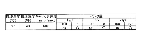
図8は、環境温度、環境湿度、キャリッジ速度、インクの吐出量と一色あたりの記録率との関係において、記録画像を視認したときに画像表面に凹凸が看取できるか否かを5段階で評価したものである。図中の評価は図7と同様である。 FIG. 8 shows, in five levels, whether or not irregularities can be observed on the image surface when the recorded image is viewed in relation to the relationship between the environmental temperature, the environmental humidity, the carriage speed, the ink ejection amount, and the recording rate per color. It has been evaluated. Evaluation in the figure is the same as in FIG.
環境温度27℃で環境湿度が40%の条件下において、キャリッジ速度600m/secで画像記録を行う場合、インク吐出量が12plと少ないときでも20plと多いときでも、一色あたりの記録率が100%である場合には凹凸が看取でき、評価は×又は△-である。これに対して、一色あたりの記録率が85%である場合には凹凸が全く看取できず、評価は○となった。 When image recording is performed at an ambient temperature of 27 ° C. and an ambient humidity of 40% at a carriage speed of 600 m / sec, the recording rate per color is 100% regardless of whether the ink ejection amount is as small as 12 pl or as large as 20 pl. In the case of, irregularities can be observed, and the evaluation is x or Δ-. On the other hand, when the recording rate per color was 85%, no irregularities could be observed, and the evaluation was good.
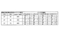
図9は、環境温度、環境湿度、キャリッジ速度、インクの種類と一色あたりの記録率との関係において、記録画像を視認したときに画像表面に凹凸が看取できるか否かを5段階で評価したものである。図中の評価は図7と同様である。 FIG. 9 evaluates whether or not irregularities can be observed on the image surface when the recorded image is visually recognized in relation to the environmental temperature, environmental humidity, carriage speed, ink type, and recording rate per color. It is a thing. Evaluation in the figure is the same as in FIG.
環境温度27℃で環境湿度が40%の条件下において、キャリッジ速度600m/secで画像記録を行う場合、一色あたりの記録率が100%である場合には、インクの種類に関わらず画像表面に凹凸が看取でき、評価は×である。これに対して、一色あたりの記録率が85%である場合にはインクの種類に関わらず凹凸が全く看取できず、評価は○となった。また、キャリッジ速度が300m/secと遅い場合には、一色あたりの記録率が100%である場合でもブラック(K)及びシアン(C)については凹凸がほとんど看取できず、評価は○-であり、記録率が85%である場合にはすべての種類のインクについて評価は○となった。また、環境温度27℃で環境湿度が75%の条件下において画像記録を行う場合には、キャリッジ速度が600m/secという速い場合であっても、記録率が90%である場合にはインクの種類に関わらず評価は○となった。 When an image is recorded at a carriage speed of 600 m / sec under an environment temperature of 27 ° C. and an ambient humidity of 40%, the recording rate per color is 100%. Unevenness can be observed, and the evaluation is x. On the other hand, when the recording rate per color was 85%, no irregularities could be observed regardless of the type of ink, and the evaluation was good. Further, when the carriage speed is as low as 300 m / sec, even when the recording rate per color is 100%, almost no irregularities can be observed for black (K) and cyan (C), and the evaluation is ○ −. Yes, when the recording rate was 85%, the evaluation for all types of inks was good. Further, when image recording is performed under the condition where the environmental temperature is 27 ° C. and the environmental humidity is 75%, even if the carriage speed is as fast as 600 m / sec, if the recording rate is 90%, the ink The evaluation was ○ regardless of the type.
図10は、環境温度、環境湿度、プラテンの温度、紫外線量と一色あたりの記録率との関係において、記録画像を視認したときに画像表面に凹凸が看取できるか否かを5段階で評価したものである。図中の評価は図7と同様である。 FIG. 10 evaluates whether or not irregularities can be observed on the image surface when the recorded image is visually recognized in relation to the environmental temperature, the environmental humidity, the temperature of the platen, the amount of ultraviolet rays, and the recording rate per color. It is a thing. Evaluation in the figure is the same as in FIG.
環境温度27℃で環境湿度が40%であってプラテンの温度が30℃の条件下で画像記録を行う場合、一色あたりの記録率が100%である場合には、照射される紫外線量に関わらず画像表面に凹凸が看取でき、評価は×である。これに対して、紫外線量が100%である場合には一色あたりの記録率が85%である場合に評価が○となり、紫外線量が50%である場合には一色あたりの記録率が80%である場合に評価が○となった。また、プラテンの温度が30℃の条件下では、紫外線量が100%である場合には一色あたりの記録率が95%である場合に評価が○となり、紫外線量が50%である場合には一色あたりの記録率が85%である場合に評価が○となった。 When image recording is performed under the conditions of an environmental temperature of 27 ° C., an environmental humidity of 40%, and a platen temperature of 30 ° C., when the recording rate per color is 100%, it is related to the amount of ultraviolet rays irradiated. Unevenness can be observed on the surface of the image, and the evaluation is x. On the other hand, when the ultraviolet ray amount is 100%, the evaluation becomes “good” when the recording rate per color is 85%, and when the ultraviolet ray amount is 50%, the recording rate per color is 80%. In the case of, the evaluation is ○. In the case where the temperature of the platen is 30 ° C., when the amount of ultraviolet rays is 100%, the evaluation is ○ when the recording rate per color is 95%, and when the amount of ultraviolet rays is 50%. The evaluation was good when the recording rate per color was 85%.
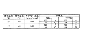
図11は、環境温度、環境湿度、キャリッジ速度、解像度と一色あたりの記録率との関係において、記録画像を視認したときに画像表面に凹凸が看取できるか否かを5段階で評価したものである。図中の評価は図7と同様である。 FIG. 11 shows an evaluation of five levels on whether the unevenness on the image surface can be observed when the recorded image is visually recognized in relation to the environmental temperature, the environmental humidity, the carriage speed, the resolution, and the recording rate per color. It is. Evaluation in the figure is the same as in FIG.
環境温度27℃で環境湿度が40%の条件下において、キャリッジ速度600m/secで画像記録を行う場合、一色あたりの記録率が100%である場合には、解像度に関わらず画像表面に凹凸が看取でき、評価は×である。これに対して、解像度が720dpiである場合には一色あたりの記録率が85%である場合に評価が○となり、解像度が1080dpiである場合には一色あたりの記録率が80%である場合に評価が○となった。また、キャリッジ速度300m/secの条件下では、解像度が720dpiである場合には一色あたりの記録率が95%である場合に評価が○となり、解像度が1080dpiである場合には一色あたりの記録率が85%である場合に評価が○となった。 When image recording is performed at a carriage speed of 600 m / sec under an environmental temperature of 27 ° C. and an environmental humidity of 40%, when the recording rate per color is 100%, the surface of the image is uneven regardless of the resolution. It can be seen and evaluation is x. On the other hand, when the resolution is 720 dpi, the evaluation is good when the recording rate per color is 85%, and when the resolution is 1080 dpi, the evaluation is 80%. The evaluation was ○. Also, under the condition of a carriage speed of 300 m / sec, when the resolution is 720 dpi, the evaluation is good when the recording rate per color is 95%, and when the resolution is 1080 dpi, the recording rate per color is Was 85 when the value was 85%.
Claims (9)
吐出された前記インクに光を照射する光源を備える光照射装置と、
前記光照射装置から照射される光の照射強度を測定する照射強度測定手段とを備え、
一色あたりの全画素を記録する記録率を100%とするとき、前記記録ヘッドによる一色あたりの最大記録率が80%以上95%以下の範囲内となるように決定する制御部を設け、
前記制御部は、前記照射強度測定手段によって測定された前記照射強度に応じて一色あたりの前記最大記録率を決定することを特徴とするインクジェット記録装置。A recording head for discharging a photocurable ink that is cured by irradiating light onto a recording medium;
A light irradiation device comprising a light source for irradiating the ejected ink with light ;
Irradiation intensity measuring means for measuring the irradiation intensity of the light irradiated from the light irradiation device ,
When the recording rate for recording all the pixels per color is 100%, a control unit is provided that determines the maximum recording rate per color by the recording head to be in the range of 80% to 95% ,
The control unit determines the maximum recording rate per color in accordance with the irradiation intensity measured by the irradiation intensity measuring unit .
吐出された前記インクに光を照射する光源を備える光照射装置とを備え、A light irradiation device including a light source for irradiating light to the ejected ink,
一色あたりの全画素を記録する記録率を100%とするとき、前記記録ヘッドによる一色あたりの最大記録率が80%以上95%以下の範囲内となるように決定する制御部を設け、When the recording rate for recording all the pixels per color is 100%, a control unit is provided that determines the maximum recording rate per color by the recording head to be in the range of 80% to 95%,
前記制御部は、画像記録時の画像記録速度に応じて一色あたりの前記最大記録率を決定することを特徴とするインクジェット記録装置。The control unit determines the maximum recording rate per color according to an image recording speed at the time of image recording.
Applications Claiming Priority (3)
| Application Number | Priority Date | Filing Date | Title |
|---|---|---|---|
| JP2004230891 | 2004-08-06 | ||
| JP2004230891 | 2004-08-06 | ||
| PCT/JP2005/013308 WO2006013726A1 (en) | 2004-08-06 | 2005-07-20 | Ink jet recorder |
Publications (2)
| Publication Number | Publication Date |
|---|---|
| JPWO2006013726A1 JPWO2006013726A1 (en) | 2008-05-01 |
| JP4375401B2 true JP4375401B2 (en) | 2009-12-02 |
Family
ID=35756977
Family Applications (1)
| Application Number | Title | Priority Date | Filing Date |
|---|---|---|---|
| JP2006531373A Active JP4375401B2 (en) | 2004-08-06 | 2005-07-20 | Inkjet recording device |
Country Status (3)
| Country | Link |
|---|---|
| US (1) | US20060028523A1 (en) |
| JP (1) | JP4375401B2 (en) |
| WO (1) | WO2006013726A1 (en) |
Families Citing this family (5)
| Publication number | Priority date | Publication date | Assignee | Title |
|---|---|---|---|---|
| JP5363434B2 (en) * | 2010-08-10 | 2013-12-11 | 富士フイルム株式会社 | Retrofit ultraviolet irradiation device and image forming apparatus |
| JP5541059B2 (en) * | 2010-10-05 | 2014-07-09 | セイコーエプソン株式会社 | Printing apparatus and printing method |
| JP6750217B2 (en) * | 2015-12-22 | 2020-09-02 | コニカミノルタ株式会社 | Inkjet recording method |
| JP7425395B2 (en) * | 2019-02-08 | 2024-01-31 | セイコーエプソン株式会社 | Inkjet method and inkjet device |
| JP7342427B2 (en) * | 2019-06-03 | 2023-09-12 | コニカミノルタ株式会社 | Inkjet recording device and inkjet recording device maintenance method |
Family Cites Families (8)
| Publication number | Priority date | Publication date | Assignee | Title |
|---|---|---|---|---|
| JP3184744B2 (en) * | 1994-06-30 | 2001-07-09 | キヤノン株式会社 | Inkjet recording method with resolution conversion |
| US6081340A (en) * | 1997-03-31 | 2000-06-27 | Xerox Corporation | Image processing method to reduce marking material coverage with non-linear specifications |
| US6322208B1 (en) * | 1998-08-12 | 2001-11-27 | Eastman Kodak Company | Treatment for improving properties of ink images |
| JP2003073481A (en) * | 2001-09-06 | 2003-03-12 | Brother Ind Ltd | Active energy ray-curable composition, ink containing the same and printer using the ink |
| JP4382364B2 (en) * | 2002-04-24 | 2009-12-09 | 株式会社東芝 | Liquid ink |
| US7056559B2 (en) * | 2002-08-30 | 2006-06-06 | Konica Corporation | Ink-jet image forming method |
| JP2004155093A (en) * | 2002-11-07 | 2004-06-03 | Canon Inc | Printing device |
| US7527345B2 (en) * | 2003-06-16 | 2009-05-05 | Seiko Epson Corporation | Print controller, method and program for print control, color conversion table, and method for determining ink quantity |
-
2005
- 2005-07-20 WO PCT/JP2005/013308 patent/WO2006013726A1/en active Application Filing
- 2005-07-20 JP JP2006531373A patent/JP4375401B2/en active Active
- 2005-07-21 US US11/186,700 patent/US20060028523A1/en not_active Abandoned
Also Published As
| Publication number | Publication date |
|---|---|
| US20060028523A1 (en) | 2006-02-09 |
| JPWO2006013726A1 (en) | 2008-05-01 |
| WO2006013726A1 (en) | 2006-02-09 |
Similar Documents
| Publication | Publication Date | Title |
|---|---|---|
| JP5028862B2 (en) | Inkjet recording device | |
| JP4026652B2 (en) | Inkjet recording apparatus and inkjet recording method | |
| JP4311491B2 (en) | Inkjet recording apparatus and inkjet recording method | |
| JP4816148B2 (en) | Inkjet recording device | |
| JP5139843B2 (en) | Inkjet printer and printing method | |
| JP5413155B2 (en) | Printing system, printing control program, and printing method | |
| JP2005074878A (en) | Image recorder | |
| JPWO2005105452A1 (en) | Inkjet recording device | |
| US7497553B2 (en) | Inkjet recording method and inkjet recording apparatus | |
| JP4375401B2 (en) | Inkjet recording device | |
| JP2005262553A (en) | Image recording apparatus | |
| JP4379316B2 (en) | Inkjet recording method and inkjet recording apparatus | |
| JP4285401B2 (en) | Image recording method and ink jet recording apparatus | |
| JP2005104116A (en) | Inkjet printer | |
| JP4715471B2 (en) | Inkjet recording device | |
| JP5393061B2 (en) | Discharge control device and discharge control method | |
| JP4457622B2 (en) | Inkjet printer | |
| JP2004195852A (en) | Ink-jet printer | |
| JP4427967B2 (en) | Image recording device | |
| JP2004299267A (en) | Inkjet printer | |
| JP4352740B2 (en) | Inkjet printer | |
| JP6546856B2 (en) | inkjet printer | |
| JP2005138460A (en) | Inkjet printer | |
| JP2004188777A (en) | Ink jet recorder | |
| JP2017132152A (en) | Ink jet printer |
Legal Events
| Date | Code | Title | Description |
|---|---|---|---|
| A131 | Notification of reasons for refusal |
Free format text: JAPANESE INTERMEDIATE CODE: A131 Effective date: 20090421 |
|
| A521 | Written amendment |
Free format text: JAPANESE INTERMEDIATE CODE: A523 Effective date: 20090618 |
|
| TRDD | Decision of grant or rejection written | ||
| A01 | Written decision to grant a patent or to grant a registration (utility model) |
Free format text: JAPANESE INTERMEDIATE CODE: A01 Effective date: 20090818 |
|
| A01 | Written decision to grant a patent or to grant a registration (utility model) |
Free format text: JAPANESE INTERMEDIATE CODE: A01 |
|
| A61 | First payment of annual fees (during grant procedure) |
Free format text: JAPANESE INTERMEDIATE CODE: A61 Effective date: 20090831 |
|
| R150 | Certificate of patent or registration of utility model |
Ref document number: 4375401 Country of ref document: JP Free format text: JAPANESE INTERMEDIATE CODE: R150 Free format text: JAPANESE INTERMEDIATE CODE: R150 |
|
| FPAY | Renewal fee payment (event date is renewal date of database) |
Free format text: PAYMENT UNTIL: 20120918 Year of fee payment: 3 |
|
| FPAY | Renewal fee payment (event date is renewal date of database) |
Free format text: PAYMENT UNTIL: 20120918 Year of fee payment: 3 |
|
| FPAY | Renewal fee payment (event date is renewal date of database) |
Free format text: PAYMENT UNTIL: 20130918 Year of fee payment: 4 |
|
| S111 | Request for change of ownership or part of ownership |
Free format text: JAPANESE INTERMEDIATE CODE: R313111 |
|
| R360 | Written notification for declining of transfer of rights |
Free format text: JAPANESE INTERMEDIATE CODE: R360 |
|
| R370 | Written measure of declining of transfer procedure |
Free format text: JAPANESE INTERMEDIATE CODE: R370 |
|
| S111 | Request for change of ownership or part of ownership |
Free format text: JAPANESE INTERMEDIATE CODE: R313111 |
|
| R350 | Written notification of registration of transfer |
Free format text: JAPANESE INTERMEDIATE CODE: R350 |