JP4375329B2 - Hybrid vehicle and control method thereof - Google Patents
Hybrid vehicle and control method thereof Download PDFInfo
- Publication number
- JP4375329B2 JP4375329B2 JP2005364825A JP2005364825A JP4375329B2 JP 4375329 B2 JP4375329 B2 JP 4375329B2 JP 2005364825 A JP2005364825 A JP 2005364825A JP 2005364825 A JP2005364825 A JP 2005364825A JP 4375329 B2 JP4375329 B2 JP 4375329B2
- Authority
- JP
- Japan
- Prior art keywords
- power
- increase
- engine
- fuel
- internal combustion
- Prior art date
- Legal status (The legal status is an assumption and is not a legal conclusion. Google has not performed a legal analysis and makes no representation as to the accuracy of the status listed.)
- Expired - Fee Related
Links
Images


Classifications
-
- Y—GENERAL TAGGING OF NEW TECHNOLOGICAL DEVELOPMENTS; GENERAL TAGGING OF CROSS-SECTIONAL TECHNOLOGIES SPANNING OVER SEVERAL SECTIONS OF THE IPC; TECHNICAL SUBJECTS COVERED BY FORMER USPC CROSS-REFERENCE ART COLLECTIONS [XRACs] AND DIGESTS
- Y02—TECHNOLOGIES OR APPLICATIONS FOR MITIGATION OR ADAPTATION AGAINST CLIMATE CHANGE
- Y02A—TECHNOLOGIES FOR ADAPTATION TO CLIMATE CHANGE
- Y02A50/00—TECHNOLOGIES FOR ADAPTATION TO CLIMATE CHANGE in human health protection, e.g. against extreme weather
- Y02A50/20—Air quality improvement or preservation, e.g. vehicle emission control or emission reduction by using catalytic converters
-
- Y—GENERAL TAGGING OF NEW TECHNOLOGICAL DEVELOPMENTS; GENERAL TAGGING OF CROSS-SECTIONAL TECHNOLOGIES SPANNING OVER SEVERAL SECTIONS OF THE IPC; TECHNICAL SUBJECTS COVERED BY FORMER USPC CROSS-REFERENCE ART COLLECTIONS [XRACs] AND DIGESTS
- Y02—TECHNOLOGIES OR APPLICATIONS FOR MITIGATION OR ADAPTATION AGAINST CLIMATE CHANGE
- Y02T—CLIMATE CHANGE MITIGATION TECHNOLOGIES RELATED TO TRANSPORTATION
- Y02T10/00—Road transport of goods or passengers
- Y02T10/60—Other road transportation technologies with climate change mitigation effect
- Y02T10/62—Hybrid vehicles
Abstract
Description
本発明は、ハイブリッド車両およびその制御方法に関する。 The present invention relates to a hybrid vehicle and a control method thereof.
従来から、ハイブリッド車両の一例として、内燃機関の動力を駆動軸に伝達するトルクコンバータと自動変速機との間にモータジェネレータを配置したものが知られている(例えば、特許文献1参照。)。このハイブリッド車両では、触媒の温度が予め定められた判断基準値よりも高い状態にあると判断された場合には、高温下でリーン雰囲気に晒されることによる触媒の劣化を抑制すべく、内燃機関の燃料カットを抑制する制御が実行される。すなわち、このハイブリッド車両では、触媒が高温状態にあるときには、所定条件下でアクセルオフ等に基づく減速要求がなされても燃料カットが禁止され、燃料カットの禁止に伴う減速度の低下を補うためにモータジェネレータにより回生制動力を発生させ、回生電力を二次電池等の蓄電装置に蓄えている。更に、このハイブリッド車両では、触媒が高温状態にあるときにアクセルオフ等に基づく減速要求がなされた場合、モータジェネレータによる回生電力が蓄電装置の充電に許容される電力である充電許容電力を超えるおそれがあれば、モータジェネレータによる回生制動力に代えて、要求される制動力を油圧ブレーキにより発生させている。また、従来から、ハイブリッド自動車の一例として、主として高温状態にある排ガス浄化用の触媒がリーン雰囲気に晒されて劣化するのを抑制するために、エンジンの間欠運転等に伴ってエンジンを停止させる際に、燃焼室に供給する燃料の量を従前の状態よりも増加させる燃料増大化処理を実行した後、燃料供給を停止させる処理を実行するものが知られている(例えば、特許文献2参照。)。
上述のように、ハイブリッド車両では、減速要求がなされたときに回生電力が蓄電装置の充電許容電力を超えるおそれがある場合、モータジェネレータによる回生制動力に代えて油圧ブレーキにより要求される制動力を発生させれば、触媒が高温状態にあってもその劣化を抑制すべく内燃機関における燃料カットを禁止することができる。しかしながら、アクセルオフ等に基づく減速力を油圧ブレーキにより速やかに発生させるのは容易ではなく、その制御も煩雑となるので、回生電力が充電許容電力を超えるおそれがある場合には、できるだけ燃料カットを許容してエンジンブレーキによる制動力を得ることが好ましい。このように蓄電装置の充電許容電力との関係から燃料カットの禁止を解除しても触媒の劣化を抑制できるようにするには、充電許容電力に基づいて燃料カットの禁止が解除されるまでに、燃料供給量を増量して触媒の温度を調整しておくとよい。ただし、充電許容電力に基づく燃料カットの禁止を解除すべきタイミングは、様々な条件によって変化するものであり、ごく単純に燃料供給量を増量したのでは、蓄電装置の充電許容電力との関係から燃料カットの禁止を解除したときに触媒を劣化抑制可能な状態にしておけなくなるおそれもある。その一方で、燃費の悪化を抑制する観点から燃料カットの禁止中に燃料供給量を増量し過ぎないようにする必要もある。 As described above, in the hybrid vehicle, when there is a possibility that the regenerative power exceeds the allowable charging power of the power storage device when the deceleration request is made, the braking force required by the hydraulic brake is used instead of the regenerative braking force by the motor generator. If generated, fuel cut in the internal combustion engine can be prohibited in order to suppress the deterioration of the catalyst even in a high temperature state. However, it is not easy to quickly generate the deceleration force based on accelerator-off etc. by the hydraulic brake, and the control becomes complicated, so if there is a possibility that the regenerative power exceeds the allowable charging power, cut the fuel as much as possible. It is preferable to allow and obtain the braking force by the engine brake. Thus, in order to be able to suppress the deterioration of the catalyst even if the prohibition of fuel cut is canceled from the relationship with the allowable charging power of the power storage device, the prohibition of fuel cut is canceled based on the allowable charging power. In addition, the temperature of the catalyst may be adjusted by increasing the fuel supply amount. However, the timing to cancel the prohibition of fuel cut based on the chargeable power varies depending on various conditions.If the amount of fuel supply is simply increased, the relationship with the chargeable power of the power storage device When the prohibition of fuel cut is canceled, there is a possibility that the catalyst cannot be kept in a state in which deterioration can be suppressed. On the other hand, it is necessary to prevent the fuel supply amount from being increased excessively while prohibiting fuel cut from the viewpoint of suppressing deterioration of fuel consumption.
そこで、本発明によるハイブリッド車両およびその制御方法は、内燃機関に対する燃料供給量の適切な増量により排ガス浄化用の触媒の劣化を良好に抑制できるようにすることを目的の一つとする。また、本発明によるハイブリッド車両およびその制御方法は、燃料供給量を増量して排ガス浄化用の触媒の劣化を抑制する際に燃料供給量の増量分をより適正に設定して燃費の悪化を抑制することを目的の一つとする。 Accordingly, an object of the hybrid vehicle and the control method thereof according to the present invention is to satisfactorily suppress the deterioration of the exhaust gas purification catalyst by appropriately increasing the amount of fuel supplied to the internal combustion engine. In addition, the hybrid vehicle and the control method thereof according to the present invention suppress the deterioration of fuel consumption by increasing the fuel supply amount more appropriately when the fuel supply amount is increased to suppress the deterioration of the exhaust gas purification catalyst. One of the purposes is to do.
本発明によるハイブリッド車両およびその制御方法は、上述の目的の少なくとも一部を達成するために以下の手段を採っている。 The hybrid vehicle and the control method thereof according to the present invention employ the following means in order to achieve at least a part of the above-described object.
本発明によるハイブリッド車両は、
内燃機関と、
前記内燃機関から排出される排ガスを浄化するための触媒を含む浄化手段と、
何れかの車軸である第1車軸と前記内燃機関の出力軸とに接続されて電力と動力の入出力を伴って前記第1車軸および前記出力軸に動力を入出力可能な電力動力入出力手段と、
前記第1車軸または該第1車軸とは異なる車軸の何れかである第2車軸に動力を入出力可能な電動機と、
前記電力動力入出力手段および前記電動機との間で電力をやりとり可能な蓄電手段と、
前記蓄電手段の状態に基づいて該蓄電手段の充電に許容される電力である充電許容電力を設定する充電許容電力設定手段と、
前記設定された充電許容電力に基づいて前記内燃機関に対する燃料供給の停止を禁止するか否か判定する燃料供給停止判定手段と、
前記内燃機関の運転状態を取得する運転状態取得手段と、
走行に要求される要求駆動力を設定する要求駆動力設定手段と、
前記取得された前記内燃機関の運転状態に基づいて、前記充電許容電力と前記触媒の温度を調整するための前記内燃機関に対する燃料供給量の増量制約との関係である燃料増量関係を設定する燃料増量関係設定手段と、
前記燃料供給停止判定手段による判定結果に応じて、前記設定された充電許容電力と前記設定された燃料増量関係とから定まる増量制約に従った前記燃料供給量の増量を伴って前記内燃機関が運転されると共に前記設定された要求駆動力に基づく駆動力が出力されるように前記内燃機関と前記電力動力入出力手段と前記電動機とを制御する制御手段と、
を備えるものである。
The hybrid vehicle according to the present invention
An internal combustion engine;
Purification means including a catalyst for purifying exhaust gas discharged from the internal combustion engine;
Power power input / output means connected to the first axle as one of the axles and the output shaft of the internal combustion engine and capable of inputting / outputting power to / from the first axle and the output shaft with input / output of power and power When,
An electric motor capable of inputting / outputting power to / from a second axle that is either the first axle or an axle different from the first axle;
Power storage means capable of exchanging power between the power drive input / output means and the electric motor;
Charge allowable power setting means for setting charge allowable power that is power allowed for charging of the power storage means based on the state of the power storage means;
Fuel supply stop determination means for determining whether or not to stop the fuel supply to the internal combustion engine based on the set allowable charge power;
Operating state acquisition means for acquiring the operating state of the internal combustion engine;
A required driving force setting means for setting a required driving force required for traveling;
Based on the obtained operating state of the internal combustion engine, a fuel that sets a fuel increase relationship that is a relationship between the allowable charging power and an increase restriction of the fuel supply amount to the internal combustion engine for adjusting the temperature of the catalyst An increase relationship setting means;
The internal combustion engine is operated with an increase in the fuel supply amount in accordance with an increase restriction determined from the set charge allowable power and the set fuel increase relationship according to the determination result by the fuel supply stop determination means. And a control means for controlling the internal combustion engine, the power power input / output means and the electric motor so that a driving force based on the set required driving force is output.
Is provided.
このハイブリッド車両では、内燃機関の運転状態に基づいて蓄電手段の充電に許容される電力として設定される充電許容電力と触媒の温度を調整するための内燃機関に対する燃料供給量の増量制約との関係である燃料増量関係が設定される。そして、蓄電手段の状態に基づいて設定された充電許容電力に基づく燃料供給の停止を禁止するか否かの判定結果に応じて、設定された充電許容電力と設定された燃料増量関係とから定まる増量制約に従った燃料供給量の増量を伴って内燃機関が運転されると共に、走行に要求される要求駆動力に基づく駆動力が出力されるように内燃機関と電力動力入出力手段と電動機とが制御される。このように、内燃機関の運転状態に基づいて燃料増量関係を設定すれば、充電許容電力に基づく燃料供給の停止を禁止するか否かの判定結果に応じて、内燃機関の運転状態に対応した燃料供給の適切な増量を行うことが可能となり、充電許容電力に基づいて内燃機関に対する燃料供給の停止の禁止が解除されても、それまでに触媒の温度を適切に調整しておくことができる。従って、このハイブリッド自動車では、充電許容電力に基づいて内燃機関に対する燃料供給の停止の禁止が解除されて燃料供給が停止されたときに排ガス浄化用の触媒の劣化を良好に抑制することが可能となる。 In this hybrid vehicle, the relationship between the allowable charging power set as the allowable power for charging the power storage means based on the operating state of the internal combustion engine and the increase in fuel supply to the internal combustion engine for adjusting the temperature of the catalyst A fuel increase relationship is set. Then, it is determined from the set charge allowable power and the set fuel increase relationship according to the determination result of whether or not to stop the fuel supply based on the charge allowable power set based on the state of the power storage means. The internal combustion engine, the power power input / output means, and the electric motor so that the internal combustion engine is operated with an increase in the fuel supply amount in accordance with the increase restriction, and a driving force based on the required driving force required for traveling is output. Is controlled. Thus, if the fuel increase relationship is set based on the operating state of the internal combustion engine, it corresponds to the operating state of the internal combustion engine according to the determination result of whether or not to stop the fuel supply based on the allowable charging power. It is possible to increase the fuel supply appropriately, and even if the prohibition of stopping the fuel supply to the internal combustion engine is lifted based on the chargeable power, the temperature of the catalyst can be adjusted appropriately until then. . Therefore, in this hybrid vehicle, it is possible to satisfactorily suppress the deterioration of the exhaust gas purification catalyst when the prohibition of stopping the fuel supply to the internal combustion engine is canceled based on the chargeable power and the fuel supply is stopped. Become.
また、前記燃料増量関係設定手段は、前記取得された前記内燃機関の運転状態が前記浄化手段に相対的に多くの排ガスを送り込む状態にあるときほど、前記充電許容電力が充電電力として相対的に小さい時点から前記燃料供給量がより増量されるように前記燃料増量関係を設定するものであってもよい。すなわち、浄化手段の触媒の温度は内燃機関からの排ガスの量に応じて変化するものであり、内燃機関の運転状態が前記浄化手段に対して相対的に多くの排ガスを送り込む状態にあるときほど、浄化手段に含まれる触媒の温度を低下させ易くなる。従って、内燃機関の運転状態が浄化手段に相対的に多くの排ガスを送り込む状態にあるときほど、充電許容電力が充電電力として相対的に小さい時点から燃料供給量がより増量されるように燃料増量関係を設定すれば、燃料供給量の増量分をより適正に設定して無駄な燃料供給量の増量による燃費の悪化を抑制しながら触媒の温度を調整することが可能となる。 Further, the fuel increase relationship setting means is configured such that the chargeable power becomes relatively larger as the charge power when the acquired operating state of the internal combustion engine is in a state where a relatively large amount of exhaust gas is fed into the purification means. The fuel increase relationship may be set so that the fuel supply amount is increased from a small time point. That is, the temperature of the catalyst of the purification means changes according to the amount of exhaust gas from the internal combustion engine, and the more the exhaust gas is fed into the purification means when the operating state of the internal combustion engine is relatively large. It becomes easy to lower the temperature of the catalyst contained in the purification means. Accordingly, the fuel increase amount is increased so that the fuel supply amount is increased from the time when the chargeable power is relatively small as the charge power, when the operation state of the internal combustion engine is a state in which a relatively large amount of exhaust gas is sent to the purification means. If the relationship is set, it is possible to adjust the temperature of the catalyst while appropriately setting the amount of increase in the fuel supply amount and suppressing deterioration in fuel consumption due to the increase in the wasteful fuel supply amount.
更に、本発明によるハイブリッド車両において、前記運転状態取得手段は、前記内燃機関の吸入空気量を検出または推定する吸入空気量取得手段であってもよく、前記燃料増量関係設定手段は、前記検出または推定された吸入空気量が多いほど、前記充電許容電力が充電電力として相対的に小さい時点から前記燃料供給量がより増量されるように前記燃料増量関係を設定するものであってもよい。すなわち、内燃機関の吸入空気量が多いほど、浄化手段に送り込まれる排ガスの量が多くなるので、浄化手段に含まれる触媒の温度を低下させ易くなる。従って、吸入空気量が多いほど充電許容電力が充電電力として相対的に小さい時点から燃料供給量がより増量されるように燃料増量関係を設定することにより、燃料供給量の増量分をより適正に設定して無駄な燃料供給量の増量による燃費の悪化を抑制しながら触媒の温度を調整することが可能となる。 Further, in the hybrid vehicle according to the present invention, the operating state acquisition means may be intake air amount acquisition means for detecting or estimating an intake air amount of the internal combustion engine, and the fuel increase relationship setting means is the detection or The fuel increase relationship may be set such that the greater the estimated intake air amount, the more the fuel supply amount is increased from the time when the charge allowable power is relatively small as the charge power. That is, as the intake air amount of the internal combustion engine increases, the amount of exhaust gas sent to the purification unit increases, and therefore the temperature of the catalyst included in the purification unit is easily lowered. Therefore, by setting the fuel increase relationship so that the larger the intake air amount is, the more the charge supply power is relatively small as the charge power, the fuel supply amount is increased. It becomes possible to adjust the temperature of the catalyst while setting and suppressing deterioration of fuel consumption due to an increase in the amount of wasteful fuel supply.
この場合、前記燃料供給停止判定手段は、前記設定された充電許容電力が充電電力として所定の限界値以上であるときに前記燃料供給の停止を禁止すべきと判断してもよく、前記燃料増量関係は、前記設定された充電許容電力が前記限界値よりも充電電力として大きい値である仮限界値以上であるときに前記増量制約を第1の増量制約とすると共に前記設定された充電許容電力が充電電力として前記仮限界値未満になると前記増量制約を前記第1の増量制約に比べて前記燃料供給量をより増量する傾向をもった第2の増量制約とする関係であり、前記燃料増量関係設定手段は、前記検出または推定された吸入空気量が多いほど、前記仮限界値を充電電力として小さくすることにより前記燃料増量関係を設定するものであってもよい。これにより、吸入空気量が多いほど充電許容電力が充電電力として相対的に小さい時点から燃料供給量がより増量されるようにする燃料増量関係を容易に設定可能となる。 In this case, the fuel supply stop determination unit may determine that the stop of the fuel supply should be prohibited when the set charge allowable power is equal to or higher than a predetermined limit value as the charge power. The relationship is that when the set charge allowable power is equal to or greater than the temporary limit value, which is larger than the limit value, as the charge power, the increase restriction is set as the first increase restriction and the set charge allowable power When the charging power becomes less than the temporary limit value, the increase restriction is set as a second increase restriction having a tendency to increase the fuel supply amount more than the first increase restriction. The relationship setting means may set the fuel increase relationship by decreasing the temporary limit value as charging power as the detected or estimated intake air amount increases. As a result, it is possible to easily set a fuel increase relationship in which the fuel supply amount is further increased from the time when the charge allowable power is relatively small as the charge power as the intake air amount increases.
また、本発明によるハイブリッド車両において、前記触媒の温度を取得する触媒温度取得手段を更に備えてもよく、前記燃料供給停止判定手段は、前記取得された触媒の温度が所定の温度域にあり、かつ前記設定された充電許容電力が充電電力として前記限界値以上であるときに前記燃料供給の停止を禁止すべきと判断するものであってもよい。 The hybrid vehicle according to the present invention may further include a catalyst temperature acquisition unit that acquires the temperature of the catalyst, and the fuel supply stop determination unit has a temperature of the acquired catalyst in a predetermined temperature range, Further, it may be determined that the stop of the fuel supply should be prohibited when the set allowable charging power is equal to or more than the limit value as the charging power.
そして、本発明によるハイブリッド車両において、前記電力動力入出力手段は、前記第1車軸と前記内燃機関の出力軸と回転可能な第3軸とに接続され、これら3軸のうちの何れか2軸に入出力される動力に基づいて定まる動力を残余の軸に入出力する3軸式動力入出力手段と、前記第3軸に動力を入出力可能な発電機とを備えるものであってもよい。 In the hybrid vehicle according to the present invention, the power / power input / output means is connected to the first axle, the output shaft of the internal combustion engine, and a rotatable third shaft, and any two of these three shafts. And a three-axis power input / output means for inputting / outputting power determined based on power input / output to / from the remaining shaft, and a generator capable of inputting / outputting power to / from the third shaft. .
本発明によるハイブリッド車両の制御方法は、内燃機関と、該内燃機関から排出される排ガスを浄化するための触媒を含む浄化手段と、何れかの車軸である第1車軸と前記内燃機関の出力軸とに接続されて電力と動力の入出力を伴って前記第1車軸および前記出力軸に動力を入出力可能な電力動力入出力手段と、前記第1車軸または該第1車軸とは異なる車軸の何れかである第2車軸に動力を入出力可能な電動機と、前記電力動力入出力手段および前記電動機との間で電力をやりとり可能な蓄電手段とを備えたハイブリッド車両の制御方法であって、
(a)前記蓄電手段の状態に基づいて該蓄電手段の充電に許容される電力として設定される充電許容電力を設定するステップと、
(b)前記設定した充電許容電力に基づいて前記内燃機関に対する燃料供給の停止を禁止するか否か判定するステップと、
(c)前記内燃機関の運転状態に基づいて、前記充電許容電力と前記触媒の温度を調整するための前記内燃機関に対する燃料供給量の増量制約との関係である燃料増量関係を設定するステップと、
(d)ステップ(b)における判定結果に応じて、前記設定した充電許容電力と前記設定した燃料増量関係とから定まる増量制約に従った前記燃料供給量の増量を伴って前記内燃機関が運転されると共に走行に要求される要求駆動力が出力されるように前記内燃機関と前記電力動力入出力手段と前記電動機とを制御するステップと、
を含むものである。
A control method for a hybrid vehicle according to the present invention includes an internal combustion engine, a purification means including a catalyst for purifying exhaust gas discharged from the internal combustion engine, a first axle as one of the axles, and an output shaft of the internal combustion engine. And an electric power / power input / output means capable of inputting / outputting power to / from the first axle and the output shaft with input / output of electric power and power, and the first axle or an axle different from the first axle. A control method for a hybrid vehicle, comprising: an electric motor capable of inputting / outputting power to / from a second axle, and an electric power driving input / output means and an electric storage means capable of exchanging electric power between the electric motor,
(A) setting a charge allowable power set as a power allowed for charging the power storage means based on a state of the power storage means;
(B) determining whether to prohibit the stop of fuel supply to the internal combustion engine based on the set allowable charging power;
(C) setting a fuel increase relationship that is a relationship between the allowable charge power and an increase restriction on the amount of fuel supply to the internal combustion engine for adjusting the temperature of the catalyst based on the operating state of the internal combustion engine; ,
(D) The internal combustion engine is operated with an increase in the fuel supply amount in accordance with an increase restriction determined from the set charge allowable power and the set fuel increase relationship according to the determination result in step (b). And controlling the internal combustion engine, the power power input / output means and the electric motor so that a required driving force required for traveling is output;
Is included.
この方法のように、内燃機関の運転状態に基づいて燃料増量関係を設定すれば、充電許容電力に基づく燃料供給の停止を禁止するか否かの判定結果に応じて、内燃機関の運転状態に対応した燃料供給の適切な増量を行うことが可能となり、充電許容電力に基づいて内燃機関に対する燃料供給の停止の禁止が解除されても、それまでに触媒の温度を適切に調整しておくことができる。従って、この方法によれば、充電許容電力に基づいて内燃機関に対する燃料供給の停止の禁止が解除されて燃料供給が停止されたときに排ガス浄化用の触媒の劣化を良好に抑制することが可能となる。 If the fuel increase relationship is set based on the operation state of the internal combustion engine as in this method, the operation state of the internal combustion engine is changed according to the determination result of whether or not to stop the fuel supply based on the allowable charge power. Appropriate increase in the corresponding fuel supply becomes possible, and even if the prohibition of stopping the fuel supply to the internal combustion engine is lifted based on the allowable charge power, the temperature of the catalyst must be adjusted appropriately by then Can do. Therefore, according to this method, it is possible to satisfactorily suppress the deterioration of the exhaust gas purifying catalyst when the prohibition of stopping the fuel supply to the internal combustion engine is canceled based on the chargeable power and the fuel supply is stopped. It becomes.
次に、本発明を実施するための最良の形態を実施例を用いて説明する。 Next, the best mode for carrying out the present invention will be described using examples.
図1は、本発明の実施例に係るハイブリッド車両の概略構成図である。図1に示すハイブリッド自動車20は、エンジン22と、エンジン22の出力軸としてのクランクシャフト26にダンパ28を介して接続された3軸式の動力分配統合機構30と、動力分配統合機構30に接続された発電可能なモータMG1と、動力分配統合機構30に接続された駆動軸としてのリングギヤ軸32aに取り付けられた減速ギヤ35と、この減速ギヤ35に接続されたモータMG2と、動力出力装置全体をコントロールするハイブリッド用電子制御ユニット(以下、「ハイブリッドECU」という)70とを備える。
FIG. 1 is a schematic configuration diagram of a hybrid vehicle according to an embodiment of the present invention. A
エンジン22は、例えばガソリンや軽油といった炭化水素系の燃料を用いて動力を出力可能な内燃機関として構成されている。エンジン22は、図2からわかるように、エアクリーナ122により清浄された空気をスロットルバルブ124を介して吸気ポートに取り入れると共に燃料噴射弁126からガソリンを噴射して吸入空気とガソリンとを混合させ、この混合気を吸気バルブ128を介して燃焼室に吸入すると共に点火プラグ130による電気火花によって爆発燃焼させて、そのエネルギにより押し下げられるピストン132の往復運動をクランクシャフト26の回転運動に変換するものである。エンジン22からの排気ガスは、一酸化炭素(CO)や炭化水素(HC)、窒素酸化物(NOx)といった有害成分を浄化する排ガス浄化触媒(三元触媒)を備えた浄化装置134を介して外部へと排出される。浄化装置134の排ガス浄化触媒は、白金(Pt)やパラジウム(Pd)等の酸化触媒と、ロジウム(Rh)等の還元触媒と、セリア(CeO2)等の助触媒等から構成されるとよい。この場合、酸化触媒の作用により排ガスに含まれるCOやHCが水(H2O)や二酸化炭素(CO2)に浄化され、還元触媒の作用により排ガスに含まれるNOxが窒素(N2)や酸素(O2)に浄化される。
The
このように構成されるエンジン22は、エンジン用電子制御ユニット(以下、エンジンECUという)24により制御される。エンジンECU24は、図2に示すように、CPU24aを中心とするマイクロプロセッサとして構成されており、CPU24aの他に処理プログラムを記憶するROM24bと、データを一時的に記憶するRAM24cと、図示しない入出力ポートおよび通信ポートとを備える。例えば、エンジンECU24には、クランクシャフト26の回転位置を検出するクランクポジションセンサ140からのクランクポジション、エンジン22の冷却水の温度を検出する水温センサ142からの冷却水温、燃焼室内の圧力である筒内圧力を検出する圧力センサ143からの筒内圧力、燃焼室へ吸排気を行なう吸気バルブ128や排気バルブを開閉するカムシャフトの回転位置を検出するカムポジションセンサ144からのカムポジション、スロットルバルブ124のポジションを検出するスロットルバルブポジションセンサ146からのスロットルポジション、吸気管に設けられたエアフローメータ148からの吸入空気量GA、同様に吸気管に設けられた温度センサ149からの吸気温度、浄化装置134に設けられた温度センサ135からの触媒床温Tcat等が入力ポートを介して入力されている。また、エンジンECU24からは、エンジン22を駆動するための種々の制御信号、例えば、燃料噴射弁126への駆動信号や、スロットルバルブ124のポジションを調節するスロットルモータ136への駆動信号、イグナイタと一体化されたイグニッションコイル138への制御信号、吸気バルブ128の開閉タイミングを変更可能な可変バルブタイミング機構150への制御信号等が出力ポートを介して出力される。なお、エンジンECU24は、ハイブリッド用電子制御ユニット70と通信しており、ハイブリッド用電子制御ユニット70からの制御信号によりエンジン22を運転制御すると共に必要に応じてエンジン22の運転状態に関するデータをハイブリッドECU70に出力する。
The
動力分配統合機構30は、外歯歯車のサンギヤ31と、このサンギヤ31と同心円上に配置された内歯歯車のリングギヤ32と、サンギヤ31に噛合すると共にリングギヤ32に噛合する複数のピニオンギヤ33と、複数のピニオンギヤ33を自転かつ公転自在に保持するキャリア34とを備え、サンギヤ31とリングギヤ32とキャリア34とを回転要素として差動作用を行なう遊星歯車機構として構成されている。キャリア34にはエンジン22のクランクシャフト26が、サンギヤ31にはモータMG1が、リングギヤ32にはリングギヤ軸32aを介して減速ギヤ35がそれぞれ連結されており、動力分配統合機構30は、モータMG1が発電機として機能するときにはキャリア34から入力されるエンジン22からの動力をサンギヤ31側とリングギヤ32側にそのギヤ比に応じて分配し、モータMG1が電動機として機能するときにはキャリア34から入力されるエンジン22からの動力とサンギヤ31から入力されるモータMG1からの動力を統合してリングギヤ32側に出力する。リングギヤ32に出力された動力は、リングギヤ軸32aからギヤ機構60およびデファレンシャルギヤ62を介して、最終的には車両の駆動輪63a,63bに出力される。
The power distribution and
モータMG1およびモータMG2は、何れも発電機として作動することができると共に電動機として作動可能な周知の同期発電電動機として構成されており、インバータ41,42を介してバッテリ50と電力のやりとりを行なう。インバータ41,42とバッテリ50とを接続する電力ライン54は、各インバータ41,42が共用する正極母線および負極母線として構成されており、モータMG1,MG2の何れかで発電される電力を他のモータで消費することができるようになっている。したがって、バッテリ50は、モータMG1,MG2の何れかから生じた電力や不足する電力により充放電されることになる。なお、モータMG1,MG2により電力収支のバランスをとるものとすれば、バッテリ50は充放電されない。モータMG1,MG2は、何れもモータ用電子制御ユニット(以下、「モータECU」という)40により駆動制御されている。モータECU40には、モータMG1,MG2を駆動制御するために必要な信号、例えばモータMG1,MG2の回転子の回転位置を検出する回転位置検出センサ43,44からの信号や図示しない電流センサにより検出されるモータMG1,MG2に印加される相電流等が入力されており、モータECU40からは、インバータ41,42へのスイッチング制御信号が出力されている。モータECU40は、ハイブリッドECU70と通信しており、ハイブリッドECU70からの制御信号によってモータMG1,MG2を駆動制御すると共に必要に応じてモータMG1,MG2の運転状態に関するデータをハイブリッドECU70に出力する。
Both the motor MG1 and the motor MG2 are configured as well-known synchronous generator motors that can operate as a generator and operate as an electric motor, and exchange power with the
バッテリ50は、バッテリ用電子制御ユニット(以下、「バッテリECU」という)52によって管理されている。バッテリECU52には、バッテリ50を管理するのに必要な信号、例えば、バッテリ50の端子間に設置された図示しない電圧センサからの端子間電圧、バッテリ50の出力端子に接続された電力ライン54に取り付けられた図示しない電流センサからの充放電電流、バッテリ50に取り付けられた温度センサ51からの電池温度Tb等が入力されており、バッテリECU52は、必要に応じてバッテリ50の状態に関するデータを通信によりハイブリッドECU70やエンジンECU24に出力する。なお、バッテリECU52は、バッテリ50を管理するために電流センサにより検出された充放電電流の積算値に基づいて残容量(SOC)も演算している。
The
ハイブリッドECU70は、CPU72を中心とするマイクロプロセッサとして構成されており、CPU72の他に処理プログラムを記憶するROM74と、データを一時的に記憶するRAM76と、図示しない入出力ポートおよび通信ポートとを備える。ハイブリッドECU70には、イグニッションスイッチ80からのイグニッション信号、シフトレバー81の操作位置であるシフトポジションSPを検出するシフトポジションセンサ82からのシフトポジションSP、アクセルペダル83の踏み込み量を検出するアクセルペダルポジションセンサ84からのアクセル開度Acc、ブレーキペダル85の踏み込み量を検出するブレーキペダルポジションセンサ86からのブレーキペダルポジションBP、車速センサ88からの車速V等が入力ポートを介して入力される。ハイブリッドECU70は、上述したように、エンジンECU24やモータECU40、バッテリECU52と通信ポートを介して接続されており、エンジンECU24やモータECU40、バッテリECU52と各種制御信号やデータのやりとりを行なっている。
The
上述のように構成された実施例のハイブリッド自動車20は、運転者によるアクセルペダル83の踏み込み量に対応するアクセル開度Accと車速Vとに基づいて駆動軸としてのリングギヤ軸32aに出力すべき要求トルクTr*を計算し、この要求トルクTr*に対応する動力がリングギヤ軸32aに出力されるように、エンジン22とモータMG1とモータMG2とが運転制御される。エンジン22とモータMG1とモータMG2の運転制御モードとしては、要求動力に見合う動力がエンジン22から出力されるようにエンジン22を運転制御すると共にエンジン22から出力される動力のすべてが動力分配統合機構30とモータMG1とモータMG2とによってトルク変換されてリングギヤ軸32aに出力されるようモータMG1およびモータMG2を駆動制御するトルク変換運転モードや、要求動力とバッテリ50の充放電に必要な電力との和に見合う動力がエンジン22から出力されるようにエンジン22を運転制御すると共にバッテリ50の充放電を伴ってエンジン22から出力される動力の全部またはその一部が動力分配統合機構30とモータMG1とモータMG2とによるトルク変換を伴って要求動力がリングギヤ軸32aに出力されるようモータMG1およびモータMG2を駆動制御する充放電運転モード、エンジン22の運転を停止してモータMG2から要求動力に見合う動力をリングギヤ軸32aに出力するように運転制御するモータ運転モード等がある。
The
次に、実施例のハイブリッド自動車20の動作、特に、エンジン22の運転を伴ったアクセルオン状態でのハイブリッド自動車20の動作について説明する。図3は、アクセルオン時にハイブリッドECU70により実行される駆動制御ルーチンの一例を示すフローチャートである。このルーチンは、アクセル操作状態がアクセルオン状態にあるときに所定時間毎(例えば数msec毎)に繰り返し実行される。
Next, the operation of the
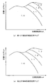
図3の駆動制御ルーチンが開始されると、ハイブリッドECU70のCPU72は、まず、アクセルペダルポジションセンサ84からのアクセル開度Acc、車速センサ88からの車速V、モータMG1,MG2の回転数Nm1,Nm2、バッテリ50が充放電すべき充放電要求パワーPb*、バッテリ50の入出力制限Win,Woutといった制御に必要なデータの入力処理を実行する(ステップS100)。この場合、モータMG1,MG2の回転数Nm1,Nm2は、回転位置検出センサ43,44により検出されるモータMG1,MG2の回転子の回転位置に基づいて計算されたものをモータECU40から通信により入力するものとした。充放電要求パワーPb*は、バッテリECU52から通信により入力するものとした。バッテリ50の入出力制限Win,Woutは、温度センサ51により検出されたバッテリ50の電池温度Tbとバッテリ50の残容量(SOC)とに基づいて設定されたものをバッテリECU52から通信により入力するものとした。なお、バッテリ50の入出力制限Win,Woutは、電池温度Tbに基づいて入出力制限Win,Woutの基本値を設定し、バッテリ50の残容量(SOC)に基づいて出力制限用補正係数と入力制限用補正係数とを設定し、設定した入出力制限Win,Woutの基本値に補正係数を乗じて設定することが可能である。図4に電池温度Tbと入出力制限Win,Woutとの関係の一例を示し、図5にバッテリ50の残容量(SOC)と入出力制限Win,Woutの補正係数との関係の一例を示す。
When the drive control routine of FIG. 3 is started, first, the
ステップS100のデータ入力処理の後、入力したアクセル開度Accおよび車速Vに基づいて駆動輪63a,63bに接続された駆動軸としてのリングギヤ軸32aに出力すべき要求トルクTr*とエンジン22に要求される要求パワーPe*とを設定する(ステップS110)。本実施例では、アクセル開度Accおよび車速Vと要求トルクTr*との関係を予め定めて要求トルク設定用マップとしてROM74に記憶しておき、アクセル開度Accおよび車速Vが与えられると当該マップからこれらに対応する要求トルクTr*を導出して設定するものとした。図6に要求トルク設定用マップの一例を示す。また、本実施例では、設定した要求トルクTr*にリングギヤ軸32aの回転数Nr(=Nm2/Gr)を乗じたものとバッテリ50が充放電すべき充放電要求パワーPb*とロスLossとの和としてエンジン22に対する要求パワーPe*を設定するものとした。続いて、ステップS110で設定したエンジン22に対する要求パワーPe*に基づいてエンジン22の目標回転数Ne*と目標トルクTe*とを設定する(ステップS120)。実施例では、エンジン22を効率よく動作させる動作ラインと要求パワーPe*とに基づいてエンジン22の目標運転ポイントとしての目標回転数Ne*と目標トルクTe*とを設定するものとした。図7に、エンジン22の動作ラインの一例と目標回転数Ne*と目標トルクTe*との相関曲線とを例示する。同図に示すように、目標回転数Ne*と目標トルクTe*は、動作ラインと要求パワーPe*(Ne*×Te*)が一定となること示す相関曲線との交点から求めることができる。
After the data input process in step S100, the required torque Tr * to be output to the
更に、ステップS120で設定した目標回転数Ne*とリングギヤ軸32aの回転数Nr(=Nm2/Gr)と動力分配統合機構30のギヤ比ρとに基づいて次式(1)を用いた計算によりモータMG1の目標回転数Nm1*を求めると共に、求めた目標回転数Nm1*と現在の回転数Nm1とに基づいて次式(2)を用いた計算によりモータMG1のトルク指令Tm1*を設定する(ステップS130)。式(1)は、動力分配統合機構30の回転要素に関連する力学的な関係式である。図8に、動力分配統合機構30における各回転要素における回転数とトルクとの力学的な関係を表す共線図を示す。図中、左のS軸はモータMG1の回転数Nm1に一致するサンギヤ31の回転数を示し、C軸はエンジン22の回転数Neに一致するキャリア34の回転数を示し、R軸はモータMG2の回転数Nm2を減速ギヤ35のギヤ比Grで除したリングギヤ32の回転数Nrを示す。また、R軸上の2つの太線矢印は、モータMG1からトルクTm1を出力したときにこのトルク出力によりリングギヤ軸32aに作用するトルクと、モータMG2から出力されるトルクTm2が減速ギヤ35を介してリングギヤ軸32aに作用するトルクとを示す。モータMG1の目標回転数Nm1*を求めるための式(1)は、この共線図における回転数の関係を用いれば容易に導くことができる。なお、式(1)中のρは、動力分配統合機構30のギヤ比(サンギヤ31の歯数/リングギヤ32の歯数)であり、式(2)中、右辺第2項の「k1」は比例項のゲインであり、右辺第3項の「k2」は積分項のゲインである。
Further, based on the target rotational speed Ne * set in step S120, the rotational speed Nr (= Nm2 / Gr) of the
Nm1*=Ne*・(1+ρ)/ρ−Nm2/(Gr・ρ) …(1)
Tm1*=前回Tm1*+k1(Nm1*−Nm1)+k2∫(Nm1*−Nm1)dt …(2)
Nm1 * = Ne * ・ (1 + ρ) / ρ−Nm2 / (Gr ・ ρ) (1)
Tm1 * = previous Tm1 * + k1 (Nm1 * −Nm1) + k2∫ (Nm1 * −Nm1) dt (2)
トルク指令Tm1*を設定すると、次式(3)および式(4)に従ってステップS100で入力したバッテリ50の出力制限Woutまたは入力制限Winと、設定したモータMG1のトルク指令Tm1*に現在のモータMG1の回転数Nm1を乗じて得られるモータMG1の消費電力との偏差をモータMG2の回転数Nm2で除することによりモータMG2から出力してもよいトルクの上下限としてのトルク制限Tmax,Tminを計算する(ステップS140)。更に、要求トルクTr*とトルク指令Tm1*と動力分配統合機構30のギヤ比ρと減速ギヤ35のギヤ比Grとを用いて次式(5)に従ってモータMG2から出力すべきトルクとしての仮モータトルクTm2tmpを計算し(ステップS150)、計算した仮モータトルクTm2tmpをトルク制限Tmax,Tminで制限することによりモータMG2のトルク指令Tm2*を設定する(ステップS160)。このようにしてモータMG2のトルク指令Tm2*を設定することにより、リングギヤ軸32aに出力する要求トルクTr*を基本的にバッテリ50の入出力制限Win,Woutの範囲内に制限したトルクとして設定することができる。なお、式(5)は、図8の共線図から容易に導き出すことができる。こうしてエンジン22の目標回転数Ne*や目標トルクTe*、モータMG1,MG2のトルク指令Tm1*,Tm2*を設定すると、エンジン22の目標回転数Ne*および目標トルクTe*をエンジンECU24に、モータMG1,MG2のトルク指令Tm1*,Tm2*をモータECU40にそれぞれ送信する(ステップS170)。目標回転数Ne*と目標トルクTe*とを受信したエンジンECU24は、受信した目標回転数Ne*と目標トルクTe*とに基づいて、ROM24bに記憶された図示しない燃料噴射量設定用マップやスロットル開度設定用マップ等を用いてエンジン22に対する燃料噴射量やスロットルバルブ124のポジション(スロットル開度)等を決定し、目標回転数Ne*と目標トルクTe*とを得るための制御を実行する。また、トルク指令Tm1*,Tm2*を受信したモータECU40は、トルク指令Tm1*に従ってモータMG1が駆動されると共にトルク指令Tm2*に従ってモータMG2が駆動されるようにインバータ41,42のスイッチング素子のスイッチング制御を行なう。
When the torque command Tm1 * is set, the current motor MG1 is added to the output limit Wout or the input limit Win of the
Tmax=(Wout*−Tm1*・Nm1)/Nm2 …(3)
Tmin=(Win−Tm1*・Nm1)/Nm2 …(4)
Tm2tmp=(Tr*+Tm1*/ρ)/Gr …(5)
Tmax = (Wout * −Tm1 * ・ Nm1) / Nm2 (3)
Tmin = (Win−Tm1 * ・ Nm1) / Nm2 (4)
Tm2tmp = (Tr * + Tm1 * / ρ) / Gr (5)
ここで、上述のようなエンジン22の運転を伴ったアクセルオン状態を経て車速Vが比較的高い所定車速以上になっているときに運転者によりアクセルペダル83の踏み込みが解除されて減速要求がなされた場合には、基本的にエンジン22に対する燃料噴射が停止され、主としてエンジンブレーキを利用しながら図6の要求トルク設定用マップから定まるアクセル開度が0%(アクセルオフ)のときの要求トルク(制動トルク)Tr*が得られるようにエンジン22、モータMG1およびMG2が制御される。ただし、浄化装置134の排ガス浄化触媒が高温状態にあるときにエンジン22に対する燃料噴射が停止されると、浄化装置134に対して燃焼室を通過した空気のみが供給され、排ガス浄化触媒がリーン雰囲気に晒されることにより酸化触媒や還元触媒が粒成長して表面積が低下してしまい、排ガス浄化触媒の劣化(浄化機能の低下)を招くおそれがある。このため、排ガス浄化触媒の温度(触媒床温Tcat)によっては、エンジン22に対する燃料噴射の停止(以下、「燃料カット」という)を禁止した上で、適宜エンジン22に対する燃料噴射量を増量補正して排ガス浄化触媒の触媒床温Tcatを調整することが好ましい。一方、燃料カットが禁止された状態でアクセルオフに基づく減速要求がなされた場合、ハイブリッド自動車20では、エンジン22、モータMG1およびMG2を制御することにより、所定の条件に従ってエンジン22への燃料噴射と点火(ファイアリング)を継続すると共にスロットルバルブ124の開度を調整してエンジン22の回転数を徐々に所定回転数(例えばアイドル時の回転数)まで低下させながら、モータMG2にエンジン22から出力されるトルクを相殺しつつ図6の要求トルク設定用マップから定まるアクセル開度が0%のときの要求トルク(制動トルク)Tr*を出力させることができる。この場合、モータMG2は制動力の発生に伴って電力を発生し、その回生電力はバッテリ50に蓄えられることになるが、バッテリ50の充電に許容される電力である充電許容電力としての入力制限Winの値によっては、このようなモータMG2による回生が制限されることもある。このため、本実施例のハイブリッド自動車20では、浄化装置134の排ガス浄化触媒の触媒床温Tcatと、バッテリ50の入力制限Winとの双方を考慮しながらエンジン22に対する燃料噴射量を増量補正して排ガス浄化触媒の劣化を抑制できるように、以下に説明する触媒劣化抑制判定ルーチンが実行される。
Here, when the vehicle speed V is higher than the relatively high predetermined vehicle speed through the accelerator-on state accompanied by the operation of the
図9は、触媒劣化抑制判定ルーチンの一例を示すフローチャートであり、このルーチンは、エンジンECU24により所定時間毎に繰り返し実行される。図9の触媒劣化抑制判定ルーチンが開始されると、エンジンECU24のCPU24aは、まず、エアフローメータ148からの吸入空気量GA、浄化装置134に設けられた温度センサ135からの触媒床温Tcat、バッテリ50の入力制限Winといった判定に必要なデータの入力処理を実行する(ステップS200)。この場合、バッテリ50の入力制限Winは、バッテリECU52から通信により入力するものとした。また、触媒床温Tcatについては、浄化装置134の温度センサ135が省略されている場合には、エンジン22の回転数Neや吸入空気量、後述の燃料噴射量の増量分等から推定されるものを入力してもよい。更に、吸入空気量GAについては、エアフローメータ148が省略されている場合には、スロットルポジションセンサ146からのスロットルポジション(スロットル開度)や、クランクポジションセンサ140からのクランクポジション(エンジン回転数Ne)、後述のスロットル開度の補正量等に基づいてエンジンECU24により計算されているものを入力してもよい。そして、ステップS200のデータ入力処理の後、入力した触媒床温Tcatが予め定められている第1の閾値Tref1以上であるか否かを判定する(ステップS210)。ここで用いられる第1の閾値Tref1は、排ガス浄化触媒の劣化が抑制される程度に触媒床温Tcatの上昇を抑制するときの第1の目標床温T1(例えば920℃)に基づいて定められるものである。
FIG. 9 is a flowchart showing an example of a catalyst deterioration suppression determination routine. This routine is repeatedly executed by the
ステップS210にて触媒床温Tcatが第1の閾値Tref1以上であって排ガス浄化触媒が高温状態にあると判断される場合には、ステップS200で入力した吸入空気量GAに基づいてバッテリ50の入力制限Winに関連する閾値としての仮限界値Win0を設定する(ステップS220)。仮限界値Win0は、アクセルオフ時に要求されるトルク(制動トルク)を燃料カットせずにモータMG2による回生制動力でまかなった場合におけるバッテリ50の入力制限値Winの限界値(充電電力としての最小値)Win1よりも小さな値、すなわち充電電力として大きな(余裕をもった)値として定められるものである。実施例では、吸入空気量GAと仮限界値Win0との関係を予め定めて図10に例示するような仮限界値設定用マップとしてROM74に記憶しておき、吸入空気量GAが与えられると当該マップからそれに対応する仮限界値Winを導出して設定するものとした。なお、入力制限Winは本来負の値であるので、入力制限Winが仮限界値Win0以下である、すなわち入力制限Winが充電電力として仮限界値Win0以上であるということは、バッテリ50を充電する電力として比較的大きな値(絶対値が大きな値)を設定できることを意味する。
If it is determined in step S210 that the catalyst bed temperature Tcat is equal to or higher than the first threshold value Tref1 and the exhaust gas purification catalyst is in a high temperature state, the input of the
続いて、ステップS200で入力した入力制限Winが仮限界値Win0以下であるか否かを判定する(ステップS230)。入力制限Winが仮限界値Win0以下である場合には、仮禁止フラグFtを値0に設定した上で(ステップS240)、上述の燃料噴射量設定用マップを用いて設定されたエンジン22に対する燃料噴射量を増量補正する増量係数を設定するためのマップとして図11(a)に例示する第1OT増量係数設定用マップをROM24bから読み出して設定すると共に、上述のスロットル開度設定用マップを用いて設定されたスロットルバルブ124の開度を補正するための第1TA補正用マップ(図示省略)をROM24bから読み出して設定し(ステップS250)、更に、燃料カットを禁止すべく、燃料カットを許容する際に値0とされる燃料カット禁止フラグFcを値1に設定して(ステップS260)、本ルーチンを一旦終了させる。
Subsequently, it is determined whether or not the input limit Win input in step S200 is equal to or less than the temporary limit value Win0 (step S230). If the input limit Win is less than or equal to the temporary limit value Win0, the temporary prohibition flag Ft is set to 0 (step S240), and the fuel for the
こうしてステップS250にて増量係数等を設定するためのマップとして第1OT増量係数設定用マップや第1TA補正用マップが設定されると、ステップS260で燃料カットが禁止され、エンジンECU24は、ハイブリッドECU70からの指令値である目標回転数Ne*および目標トルクTe*や燃料カット禁止時の所定の制約に基づいてエンジン22に対する燃料噴射量やスロットルバルブ124の開度を設定する際に、これらのマップから導出される燃料噴射量の増量係数やスロットル開度の補正係数に応じた燃料噴射量の増量やスロットル開度補正を実行する。第1OT増量係数設定用マップは、図11(a)に例示するように、エンジン22の目標回転数Ne*と吸入空気量に関連した体積効率KLとに応じて増量係数を規定するものであり、基本的に目標回転数Ne*と体積効率KLとが大きくなるにつれて増量係数として大きな値をとるように作成されている。本実施例において、第1OT増量係数設定用マップは、エンジン22の目標回転数Ne*と体積効率KLとに応じて触媒床温Tcatを概ね上述の第1の目標床温T1に保ってその上昇を抑制するための燃料噴射量の増量係数を規定するように作成されている。これにより、第1OT増量係数設定用マップが設定された際には、燃料噴射量の増量分は比較的少なくなるので、排ガス浄化触媒の劣化を抑制するための温度調整に要する燃費を低減することができる。なお、図示しない第1TA補正用マップは、第1OT増量係数設定用マップに基づいて燃料噴射量を増量したことに起因する目標トルクTe*と実際にエンジン22から出力されるトルクとの偏差がキャンセルされるように目標回転数Ne*と目標トルクTe*とに応じたスロットル開度の補正係数を規定するものとして予め作成される。すなわち、第1TA補正用マップにおけるスロットル開度の補正係数は、例えば燃料噴射量の増量時にトルクが増加する運転領域についてはスロットル開度を通常よりも小さくするものとして設定され、燃料噴射量の増量時にトルクが減少する運転領域についてはスロットル開度を通常よりも小さくするように定められる。これにより、第1OT増量係数設定用マップを用いて燃料噴射量の増量補正が実行された際に、目標トルクTe*と実際にエンジン22から出力されるトルクとの偏差に起因するショックを低減することができる。
Thus, when the first OT increase coefficient setting map or the first TA correction map is set as a map for setting the increase coefficient in step S250, the fuel cut is prohibited in step S260, and the
これに対して、ステップS230にて入力制限Winが仮限界値Win0を上回っていると判断された場合には、入力制限Winが仮限界値Win0以下である場合に値0とされる仮禁止フラグFtを値1に設定した上で(ステップS270)、ステップS200で入力した入力制限Winが上述の限界値Win1以下であるか否かを判定する(ステップS280)。入力制限Winが限界値Win1以下である、すなわち充電電力として限界値Win1以上である場合には、上述の燃料噴射量設定用マップを用いて設定されたエンジン22に対する燃料噴射量を増量補正する増量係数を設定するためのマップとして第1OT増量係数設定用マップに比べて燃料噴射量をより増量する傾向をもった図11(b)に例示する第2OT増量係数設定用マップをROM24bから読み出して設定すると共に、上述のスロットル開度設定用マップを用いて設定されたスロットルバルブ124の開度を補正するための第2TA補正用マップ(図示省略)をROM24bから読み出して設定し(ステップS290)、更に燃料カット禁止フラグFcを値1に設定して(ステップS260)、本ルーチンを一旦終了させる。また、ステップS280にて入力制限Winが限界値Win1を上回っていると判断された場合には、仮禁止フラグFtを値0に設定した上で(ステップS320)、バッテリ50の状態に応じて燃料カットの禁止を解除すべく燃料カット禁止フラグFcを値0に設定する(ステップS330)。
On the other hand, if it is determined in step S230 that the input limit Win exceeds the temporary limit value Win0, the temporary prohibition flag that is set to 0 when the input limit Win is equal to or less than the temporary limit value Win0. After setting Ft to the value 1 (step S270), it is determined whether or not the input limit Win input in step S200 is equal to or less than the limit value Win1 (step S280). When the input limit Win is equal to or less than the limit value Win1, that is, when the charging power is equal to or greater than the limit value Win1, the increase for correcting the increase in the fuel injection amount for the
こうしてステップS290にて増量係数等を設定するためのマップとして第2OT増量係数設定用マップや第2TA補正用マップが設定された場合も、ステップS270で燃料カットが禁止され、エンジンECU24は、ハイブリッドECU70からの目標回転数Ne*や目標トルクTe*等に基づいてエンジン22に対する燃料噴射量やスロットルバルブ124の開度を設定する際に、これらのマップから導出される燃料噴射量の増量係数やスロットル開度の補正係数に応じた燃料噴射量の増量やスロットル開度補正を実行する。第2OT増量係数設定用マップも、図11(b)に例示するように、エンジン22の目標回転数Ne*と吸入空気量に関連した体積効率KLとに応じて増量係数を規定するものであり、基本的に目標回転数Ne*と体積効率KLとが大きくなるにつれて増量係数として大きな値をとるように作成されている。本実施例において、第2OT増量係数設定用マップは、エンジン22の目標回転数Ne*と体積効率KLとに応じて触媒床温Tcatを排ガス浄化触媒がリーン雰囲気に晒されても劣化するおそれの少ない第2の目標床温T2(例えば850℃)まで低下させるための燃料噴射量の増量係数を規定するように作成されている。すなわち、第2OT増量係数設定用マップは、第1OT増量係数設定用マップに比べて目標回転数Ne*と体積効率KLとが比較的低いうちにより大きな増量係数をとるように作成されており、第2OT増量係数設定用マップの設定時には、第1OT増量係数設定用マップの設定時に比べて、基本的に車速Vが高いほど燃料噴射量の増量分が多くなる。また、図示しない第2TA補正用マップは、第2OT増量係数設定用マップに基づいて燃料噴射量を増量したことに起因する目標トルクTe*と実際にエンジン22から出力されるトルクとの偏差がキャンセルされるように目標回転数Ne*と目標トルクTe*とに応じたスロットル開度の補正係数を規定するものとして予め作成される。これにより、第2OT増量係数設定用マップを用いて燃料噴射量の増量補正が実行された際にも、目標トルクTe*と実際にエンジン22から出力されるトルクとの偏差に起因するショックを低減することができる。
Thus, even when the second OT increase coefficient setting map or the second TA correction map is set as the map for setting the increase coefficient in step S290, the fuel cut is prohibited in step S270, and the
このように、実施例のハイブリッド自動車20では、バッテリ50の入力制限Winと仮限界値Win0との比較の結果に応じて、燃料噴射量の増量分を定めるための第1OT増量係数設定用マップと第2OT増量係数設定用マップとの何れかが選択されるが、閾値としての仮限界値Win0は、第2OT増量係数設定用マップを用いて燃料噴射量を増量することを前提として次のように定められる。すなわち、仮限界値Win0は、基本的に次式(6)に従い、触媒床温Tcatが排ガス浄化触媒の劣化が抑制される程度に温度上昇を抑制するときの第1の目標床温T1に概ね一致しているときに第2OT増量係数設定用マップを用いて燃料噴射量を増量して触媒床温Tcatを排ガス浄化触媒がリーン雰囲気に晒されても劣化するおそれの少ない第2の目標床温T2まで低下させるのに要する最小時間Tを実験・解析により求め、求めた最小時間Tに入力制限Winの単位時間あたりの最大変化量ΔWinを乗じた値と限界値Win1とを加算することにより定められる。ここで、式(6)における最小時間Tは、ハイブリッド自動車20のエンジン22の運転状態に応じて変化するものである。すなわち、エンジン22の吸入空気量GAが多いほど、浄化装置134に対して多くの排ガスが送り込まれ、排ガスにより排ガス浄化用触媒から持ち去られる熱エネルギが多くなるので、排ガス浄化触媒の温度を低下させ易くなり、式(6)における最小時間Tは短くなる。このため、当該最小時間Tを一定として仮限界値Win0を定めると、吸入空気量GAとの関係で最小時間Tが比較的短い状態であるにも拘わらず、バッテリ50の入力制限Winに比較的余裕がある段階から第2OT増量係数設定用マップが設定され、無駄な燃料噴射量の増量が行われてしまうおそれもある。このような点を考慮して、実施例では、吸入空気量GAごとの最小時間Tを解析等により求めた上で、式(6)に基づいて吸入空気量GAと仮限界値Win0との関係を規定する仮限界値設定用マップを予め作成している。図10に示すように、仮限界値設定用マップは、基本的に、吸入空気量が多いほど仮限界値Win0の値として大きな値(絶対値が小さな値)をとるように作成される。
Thus, in the
Win0=Win1+ΔWin・T …(6) Win0 = Win1 + ΔWin · T (6)
また、上述のようにステップS270で仮禁止フラグFtが値1とされると共にステップS290で第2OT増量係数設定用マップが設定されると、基本的に触媒床温Tcatは低下していくので、触媒劣化抑制判定ルーチンが再度実行された際にステップS200にて入力した触媒床温Tcatが第1の閾値Tref1未満であると判断されることがあり、触媒床温Tcatが第1の閾値Tref1未満であるときには、仮禁止フラグFtが値1であるか否かを判定し(ステップS300)、仮禁止フラグFtが値1であれば、入力した触媒床温Tcatが上述の第2の目標床温T2に基づいて定められる第2の閾値Tref2未満であるか否かを判定する(ステップS310)。触媒床温Tcatが第2の閾値Tref2以上である場合には、入力した入力制限Winが限界値Win1以下であるか否かを判定し(ステップS280)、入力制限Winが限界値Win1以下であれば、第2OT増量係数設定用マップと第2TA補正用マップとをROM24bから読み出して設定すると共に(ステップS290)、燃料カットを禁止すべく燃料カット禁止フラグFcを値1に設定して(ステップS260)、本ルーチンを一旦終了させる。また、入力制限Winが限界値Win1を上回っていれば、仮禁止フラグFtを値0に設定した上で(ステップS320)、バッテリ50の状態に応じて燃料カットの禁止を解除すべく燃料カット禁止フラグFcを値0に設定する(ステップS330)。これに対して、触媒床温Tcatが第2の閾値Tref2未満である場合には、排ガス浄化触媒がリーン雰囲気に晒されても劣化するおそれの少ない第2の目標床温T2まで触媒床温Tcatが低下しているとみなし、仮禁止フラグFtを値0に設定した上で(ステップS320)、燃料カットの禁止を解除すべく燃料カット禁止フラグFcを値0に設定する(ステップS330)。更に、ステップS300で仮禁止フラグFtが値0であると判断される場合、第2OT増量係数設定用マップに従った燃料噴射量の増量を行うことなく触媒床温Tcatが比較的低温の状態にあることになるので、この場合は、燃料カットを許容しても排ガス浄化触媒が劣化するおそれが少ないとみなして、燃料カット禁止フラグFcを値0に設定する(ステップS330)。
As described above, when the temporary prohibition flag Ft is set to the
上述した一連の処理が実行されたときの入力制限Winの推移、触媒床温Tcatの時間的推移、増量係数や燃料カット禁止フラグFc、仮禁止フラグFtの設定状態を図12のタイムチャートに例示する。なお、入力制限Winは、必ずしも時間変化に依存するものではないが、図12では、説明をわかりやすくするために経時的に変化するものとして示している。図12からわかるように、排ガス浄化触媒が高温状態(Tcat≧Tref1)にあるときにバッテリ50の状態に応じて第1OT増量係数設定用マップが設定されると、当該マップに従ってエンジン22に対する燃料噴射量が増量補正され、基本的に触媒床温Tcatが概ね第1の目標床温T1に保たれることになる。また、ガス浄化触媒が所定の温度域(例えば、850℃を超える領域)にあり、かつバッテリ50の入力制限Winが仮限界値Win0から限界値Win1の範囲内にあるときには、仮禁止フラグFtが値1とされると共に第2OT増量係数設定用マップが設定され、基本的に触媒床温Tcatが概ね第2の目標床温T2まで低下するようにエンジン22に対する燃料噴射量が増量補正されることになる。そして、実施例のハイブリッド自動車20において、仮限界値Win0は、上述のようにエンジン22の吸入空気量GAが多いほど充電電力として小さく設定されるので(図12におけるWin0′参照)、吸入空気量GAが多い時には、図12において一点鎖線で示すように、同図において実線で示す吸入空気量GAが少ない時に比べてバッテリ50の入力制限Winが限界値Win1に近づいた段階から、触媒床温Tcatを排ガス浄化触媒がリーン雰囲気に晒されても劣化するおそれの少ない第2の目標床温T2まで低下させるべく第2OT増量係数設定用マップを用いた燃料噴射量の増量が開始されることになる。
The time chart of FIG. 12 illustrates the transition of the input limit Win, the temporal transition of the catalyst bed temperature Tcat, the setting condition of the increase coefficient, the fuel cut prohibition flag Fc, and the temporary prohibition flag Ft when the above-described series of processing is executed. To do. Note that the input restriction Win does not necessarily depend on a change with time, but in FIG. 12, it is shown as a change with time in order to make the description easy to understand. As can be seen from FIG. 12, when the first OT increase coefficient setting map is set according to the state of the
以上説明したように、本実施例のハイブリッド自動車20では、エンジン22の運転状態を示す吸入空気量GAに基づいてバッテリ50の入力制限Winと排ガス浄化触媒の温度を調整するためのエンジン22に対する燃料噴射量の増量制約としての第1および第2OT増量係数設定用マップとの関係を定める仮限界値Win0が設定される。そして、入力制限Winに基づいて行われる燃料カットを禁止するか否かの判定結果に応じた燃料カットの禁止時(アクセルオン時と燃料噴射継続時とを含む)には、入力制限Winと仮限界値Win0とに基づいて設定される第1または第2OT増量係数設定用マップに従った燃料噴射量の増量を伴ってエンジン22が運転されると共に、設定された要求トルクTr*に基づく駆動力(制動力)が出力されるようにエンジン22、モータMG1およびMG2が制御される。このように、エンジン22の運転状態を示す吸入空気量GAに基づいて仮限界値Win0を設定すれば、バッテリ50の入力制限Winに基づく燃料カットを禁止するか否かの判定結果に応じて、エンジン22の運転状態に基づいて定まる浄化装置134への排ガス供給量に対応した燃料噴射量の適切な増量を行うことが可能となり、バッテリ50の入力制限Winに基づいて燃料カットの禁止が解除されても、それまでに排ガス浄化触媒の温度を適切に調整しておくことができる。従って、ハイブリッド自動車20では、バッテリ50の入力制限Winに基づいて燃料カットの禁止が解除されて実際に燃料カットが実行されたときに排ガス浄化触媒の劣化を良好に抑制することが可能となる。
As described above, in the
すなわち、ハイブリッド自動車20では、エンジン22の吸入空気量GAが多いほど、浄化装置134に送り込まれる排ガスの量が多くなるので、浄化装置134に含まれる排ガス浄化触媒の温度を低下させ易くなる。従って、エンジン22の運転状態がより多くの空気を吸入してより多くの排ガスを浄化装置134に送り込む状態にあるときほど、仮限界値Win0を充電電力として小さい値に設定してバッテリ50の入力制限Winが充電電力として相対的に小さい時点から燃料噴射量がより増量されるようにすれば、燃料噴射量の増量分をより適正に設定して無駄な燃料噴射量の増量による燃費の悪化を抑制しながら排ガス浄化触媒の温度を調整することが可能となる。また、バッテリ50の入力制限Winが充電電力として仮限界値Win0以上であるときに第1OT増量係数設定用マップを用いると共にバッテリ50の入力制限Winが充電電力として仮限界値Win0未満になると第1OT増量係数設定用マップに比べて燃料噴射量をより増量する傾向をもった第2OT増量係数用マップを用いる場合には、吸入空気量GAが多いほど仮限界値Win0を充電電力として小さくすれば、吸入空気量GAが多いほど限界値Win1に近づいた段階から燃料噴射量をより増量させることを容易に実行可能となる。
That is, in the
以上、実施例を用いて本発明の実施の形態について説明したが、本発明は上記実施例に何ら限定されるものではなく、本発明の要旨を逸脱しない範囲内において、様々な変更をなし得ることはいうまでもない。 The embodiments of the present invention have been described above using the embodiments. However, the present invention is not limited to the above embodiments, and various modifications can be made without departing from the scope of the present invention. Needless to say.
すなわち、上記実施例のハイブリッド自動車20では、駆動軸としてのリングギヤ軸32aとモータMG2とがモータMG2の回転数を減速してリングギヤ軸32aに伝達する減速ギヤ35を介して連結しているが、減速ギヤ35の代わりに、例えばHi,Loの2段の変速段あるいは3段以上の変速段を有し、モータMG2の回転数を変速してリングギヤ軸32aに伝達する変速機を採用してもよい。
That is, in the
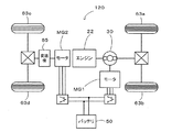
また、上記実施例のハイブリッド自動車20では、モータMG2の動力を減速ギヤ35により減速してリングギヤ軸32aに出力しているが、図13に示す変形例としてのハイブリッド自動車120のように、モータMG2の動力を変速機65により変速してリングギヤ軸32aが接続された車軸(駆動輪63a,63bが接続された車軸)とは異なる車軸(図13中、車輪63c,63dに接続された車軸)に伝達するようにしてもよい。
Further, in the
更に、上記各実施例のハイブリッド自動車20は、エンジン22の動力を動力分配統合機構30を介して駆動輪63a,63bに接続された駆動軸としてのリングギヤ軸32aに出力するものであるが、図14に示す変形例としてのハイブリッド自動車220のように、エンジン22のクランクシャフト26に接続されたインナーロータ232と駆動輪63a,63bに動力を出力する駆動軸に接続されたアウターロータ234とを有し、エンジン22の動力の一部を駆動軸に伝達すると共に残余の動力を電力に変換する対ロータ電動機230を備えるものであってもよい。
Further, the
20,120,220 ハイブリッド自動車、22 エンジン、24 エンジン用電子制御ユニット(エンジンECU)、24a,72 CPU、24b,74 ROM、24c,76 RAM、26 クランクシャフト、28 ダンパ、30 動力分配統合機構、31 サンギヤ、32 リングギヤ、32a リングギヤ軸、33 ピニオンギヤ、34 キャリア、35 減速ギヤ、40 モータ用電子制御ユニット(モータECU)、41,42 インバータ、43,44 回転位置検出センサ、50 バッテリ、51 温度センサ、52 バッテリ用電子制御ユニット(バッテリECU)、54 電力ライン、60 ギヤ機構、62 デファレンシャルギヤ、63a,63b 駆動輪、63c,63d 車輪、65 変速機、70 ハイブリッド用電子制御ユニット(ハイブリッドECU)、80 イグニッションスイッチ、81 シフトレバー、82 シフトポジションセンサ、83 アクセルペダル、84 アクセルペダルポジションセンサ、85 ブレーキペダル、86 ブレーキペダルポジションセンサ、88 車速センサ、122 エアクリーナ、124 スロットルバルブ、126 燃料噴射弁、128 吸気バルブ、130 点火プラグ、132 ピストン、134 浄化装置、135 温度センサ、136 スロットルモータ、138 イグニッションコイル、140 クランクポジションセンサ、142 水温センサ、143 圧力センサ、144 カムポジションセンサ、146 スロットルバルブポジションセンサ、148 エアフローメータ、149 温度センサ、150 可変バルブタイミング機構、230 対ロータ電動機、232 インナーロータ、234 アウターロータ、MG1,MG2 モータ。 20, 120, 220 Hybrid vehicle, 22 engine, 24 engine electronic control unit (engine ECU), 24a, 72 CPU, 24b, 74 ROM, 24c, 76 RAM, 26 crankshaft, 28 damper, 30 power distribution integration mechanism, 31 sun gear, 32 ring gear, 32a ring gear shaft, 33 pinion gear, 34 carrier, 35 reduction gear, 40 electronic control unit for motor (motor ECU), 41, 42 inverter, 43, 44 rotational position detection sensor, 50 battery, 51 temperature sensor , 52 battery electronic control unit (battery ECU), 54 power line, 60 gear mechanism, 62 differential gear, 63a, 63b driving wheel, 63c, 63d wheel, 65 transmission, 70 electronic control for hybrid Unit (hybrid ECU), 80 ignition switch, 81 shift lever, 82 shift position sensor, 83 accelerator pedal, 84 accelerator pedal position sensor, 85 brake pedal, 86 brake pedal position sensor, 88 vehicle speed sensor, 122 air cleaner, 124 throttle valve, 126 Fuel injection valve, 128 Intake valve, 130 Spark plug, 132 Piston, 134 Purification device, 135 Temperature sensor, 136 Throttle motor, 138 Ignition coil, 140 Crank position sensor, 142 Water temperature sensor, 143 Pressure sensor, 144 Cam position sensor, 146 Throttle valve position sensor, 148 Air flow meter, 149 Temperature sensor, 150 Variable valve Timing mechanism, 230 pair-rotor motor, 232 an inner rotor, 234 outer rotor, MG1, MG2 motor.
Claims (4)
前記内燃機関から排出される排ガスを浄化するための触媒を含む浄化手段と、
何れかの車軸である第1車軸と前記内燃機関の出力軸とに接続されて電力と動力の入出力を伴って前記第1車軸および前記出力軸に動力を入出力可能な電力動力入出力手段と、
前記第1車軸または該第1車軸とは異なる車軸の何れかである第2車軸に動力を入出力可能な電動機と、
前記電力動力入出力手段および前記電動機との間で電力をやりとり可能な蓄電手段と、
前記蓄電手段の状態に基づいて該蓄電手段の充電に許容される電力である充電許容電力を設定する充電許容電力設定手段と、
前記設定された充電許容電力が充電電力として所定の限界値以上であるときに前記燃料供給の停止を禁止すべきと判断する燃料供給停止判定手段と、
前記内燃機関の運転状態を取得する運転状態取得手段と、
走行に要求される要求駆動力を設定する要求駆動力設定手段と、
前記取得された前記内燃機関の運転状態に基づいて、前記充電許容電力と前記触媒の温度を調整するための前記内燃機関に対する燃料供給量の増量制約との関係である燃料増量関係を設定する燃料増量関係設定手段と、
前記燃料供給停止判定手段による判定結果に応じて、前記設定された充電許容電力と前記設定された燃料増量関係とから定まる増量制約に従った前記燃料供給量の増量を伴って前記内燃機関が運転されると共に前記設定された要求駆動力に基づく駆動力が出力されるように前記内燃機関と前記電力動力入出力手段と前記電動機とを制御する制御手段と、
を備え、
前記燃料増量関係設定手段は、前記限界値よりも充電電力として大きい値である仮限界値を前記取得された前記内燃機関の運転状態が前記浄化手段により多くの排ガスを送り込む状態にあるときほど充電電力として小さく設定し、前記設定された充電許容電力が充電電力として前記仮限界値以上であるときに前記増量制約を第1の増量制約とすると共に、前記設定された充電許容電力が充電電力として前記仮限界値未満になると前記増量制約を前記第1の増量制約に比べて前記燃料供給量をより増量する傾向をもった第2の増量制約
とするハイブリッド車両。 An internal combustion engine;
Purification means including a catalyst for purifying exhaust gas discharged from the internal combustion engine;
Power power input / output means connected to the first axle as one of the axles and the output shaft of the internal combustion engine and capable of inputting / outputting power to / from the first axle and the output shaft with input / output of power and power When,
An electric motor capable of inputting / outputting power to / from a second axle that is either the first axle or an axle different from the first axle;
Power storage means capable of exchanging power between the power drive input / output means and the electric motor;
Charge allowable power setting means for setting charge allowable power that is power allowed for charging of the power storage means based on the state of the power storage means;
Fuel supply stop determination means for determining that the stop of fuel supply should be prohibited when the set charge allowable power is equal to or greater than a predetermined limit value as charge power;
Operating state acquisition means for acquiring the operating state of the internal combustion engine;
A required driving force setting means for setting a required driving force required for traveling;
Based on the obtained operating state of the internal combustion engine, a fuel that sets a fuel increase relationship that is a relationship between the allowable charging power and an increase restriction of the fuel supply amount to the internal combustion engine for adjusting the temperature of the catalyst An increase relationship setting means;
The internal combustion engine is operated with an increase in the fuel supply amount in accordance with an increase restriction determined from the set charge allowable power and the set fuel increase relationship according to the determination result by the fuel supply stop determination means. And a control means for controlling the internal combustion engine, the power power input / output means and the electric motor so that a driving force based on the set required driving force is output.
With
The fuel increase relationship setting means charges the temporary limit value, which is a value larger than the limit value as the charging power, when the acquired operating state of the internal combustion engine is in a state where more exhaust gas is fed into the purification means. When the set charge allowable power is equal to or greater than the temporary limit value as the charge power, the increase restriction is set as the first increase restriction, and the set charge allowable power is set as the charge power. A hybrid vehicle that uses the increase restriction as a second increase restriction having a tendency to increase the fuel supply amount more than the first increase restriction when less than the temporary limit value.
前記運転状態取得手段は、前記内燃機関の吸入空気量を検出または推定する吸入空気量取得手段であり、
前記燃料増量関係設定手段は、前記検出または推定された吸入空気量が多いほど、前記仮限界値を充電電力として小さく設定するハイブリッド車両。 The hybrid vehicle according to claim 1 ,
The operating state acquisition means is intake air amount acquisition means for detecting or estimating the intake air amount of the internal combustion engine,
The fuel increase relationship setting means is a hybrid vehicle in which the temporary limit value is set smaller as charging power as the detected or estimated intake air amount increases.
前記触媒の温度を取得する触媒温度取得手段を更に備え、
前記燃料供給停止判定手段は、前記取得された触媒の温度が所定の温度域にあり、かつ前記設定された充電許容電力が充電電力として前記限界値以上であるときに前記燃料供給の停止を禁止すべきと判断するハイブリッド車両。 The hybrid vehicle according to claim 2,
A catalyst temperature acquisition means for acquiring the temperature of the catalyst;
The fuel supply stop determination means prohibits the fuel supply stop when the acquired catalyst temperature is in a predetermined temperature range and the set charge allowable power is equal to or higher than the limit value as charge power. A hybrid vehicle that should be judged.
The power power input / output means is connected to the first axle, the output shaft of the internal combustion engine, and a rotatable third shaft, and based on power input / output to any two of these three shafts. 4. The hybrid vehicle according to claim 1, further comprising: a three-axis power input / output unit that inputs / outputs a fixed power to / from a remaining shaft; and a generator that can input / output power to / from the third shaft. 5. .
Priority Applications (1)
| Application Number | Priority Date | Filing Date | Title |
|---|---|---|---|
| JP2005364825A JP4375329B2 (en) | 2005-12-19 | 2005-12-19 | Hybrid vehicle and control method thereof |
Applications Claiming Priority (1)
| Application Number | Priority Date | Filing Date | Title |
|---|---|---|---|
| JP2005364825A JP4375329B2 (en) | 2005-12-19 | 2005-12-19 | Hybrid vehicle and control method thereof |
Publications (2)
| Publication Number | Publication Date |
|---|---|
| JP2007168471A JP2007168471A (en) | 2007-07-05 |
| JP4375329B2 true JP4375329B2 (en) | 2009-12-02 |
Family
ID=38295636
Family Applications (1)
| Application Number | Title | Priority Date | Filing Date |
|---|---|---|---|
| JP2005364825A Expired - Fee Related JP4375329B2 (en) | 2005-12-19 | 2005-12-19 | Hybrid vehicle and control method thereof |
Country Status (1)
| Country | Link |
|---|---|
| JP (1) | JP4375329B2 (en) |
Families Citing this family (4)
| Publication number | Priority date | Publication date | Assignee | Title |
|---|---|---|---|---|
| KR100999805B1 (en) | 2008-12-15 | 2010-12-08 | 콘티넨탈 오토모티브 시스템 주식회사 | Method for controlling injection of fuel of vehicle |
| JP2013007375A (en) | 2011-05-24 | 2013-01-10 | Nissan Motor Co Ltd | Fuel injection control apparatus for internal combustion engine |
| DE112013006995B4 (en) * | 2013-04-25 | 2023-10-26 | Toyota Jidosha Kabushiki Kaisha | Control unit for a vehicle |
| CN110834623B (en) * | 2019-11-11 | 2021-04-06 | 常熟理工学院 | Full hybrid vehicle energy efficiency optimization method based on sequential selection genetic algorithm |
-
2005
- 2005-12-19 JP JP2005364825A patent/JP4375329B2/en not_active Expired - Fee Related
Also Published As
| Publication number | Publication date |
|---|---|
| JP2007168471A (en) | 2007-07-05 |
Similar Documents
| Publication | Publication Date | Title |
|---|---|---|
| JP4293182B2 (en) | Hybrid vehicle and control method thereof | |
| JP4175370B2 (en) | Hybrid vehicle and control method thereof | |
| JP4175371B2 (en) | INTERNAL COMBUSTION ENGINE DEVICE, ITS CONTROL METHOD, AND POWER OUTPUT DEVICE | |
| JP4254762B2 (en) | Power output apparatus, automobile equipped with the same, and control method of power output apparatus | |
| JP4615037B2 (en) | Hybrid vehicle and control method thereof | |
| JP4165597B2 (en) | POWER OUTPUT DEVICE, INTERNAL COMBUSTION ENGINE DEVICE, CONTROL METHOD THEREOF, AND VEHICLE | |
| JP2008106675A (en) | Hybrid vehicle and method for controlling same | |
| JP2007218102A (en) | Power output device, method for controlling same and vehicle mounting same | |
| JP4293183B2 (en) | Hybrid vehicle and control method thereof | |
| JP5217991B2 (en) | Hybrid vehicle and control method thereof | |
| JP2010188935A (en) | Hybrid vehicle and control method | |
| JP4293184B2 (en) | Hybrid vehicle and control method thereof | |
| JP4375329B2 (en) | Hybrid vehicle and control method thereof | |
| JP2007120382A (en) | Power output device, method for controlling the same and vehicle | |
| JP2008189267A (en) | Hybrid vehicle and its control method | |
| JP4229116B2 (en) | Hybrid vehicle and control method thereof | |
| JP2010105626A (en) | Vehicle and control method therefor | |
| JP4215051B2 (en) | Hybrid vehicle and control method thereof | |
| JP4438752B2 (en) | POWER OUTPUT DEVICE, ITS CONTROL METHOD, AND VEHICLE | |
| JP2006070820A (en) | Drive device, automobile equipped with the same and method for controlling the drive device | |
| JP5751185B2 (en) | Hybrid car | |
| JP2009279965A (en) | Hybrid vehicle and method of controlling the same | |
| JP4862687B2 (en) | Internal combustion engine device, power output device, and control method thereof | |
| JP2009248682A (en) | Hybrid vehicle and control method thereof | |
| JP2013067297A (en) | Hybrid vehicle |
Legal Events
| Date | Code | Title | Description |
|---|---|---|---|
| A621 | Written request for application examination |
Free format text: JAPANESE INTERMEDIATE CODE: A621 Effective date: 20080216 |
|
| A131 | Notification of reasons for refusal |
Free format text: JAPANESE INTERMEDIATE CODE: A131 Effective date: 20080826 |
|
| A521 | Request for written amendment filed |
Free format text: JAPANESE INTERMEDIATE CODE: A523 Effective date: 20081008 |
|
| A131 | Notification of reasons for refusal |
Free format text: JAPANESE INTERMEDIATE CODE: A131 Effective date: 20090317 |
|
| A521 | Request for written amendment filed |
Free format text: JAPANESE INTERMEDIATE CODE: A523 Effective date: 20090514 |
|
| A131 | Notification of reasons for refusal |
Free format text: JAPANESE INTERMEDIATE CODE: A131 Effective date: 20090609 |
|
| A521 | Request for written amendment filed |
Free format text: JAPANESE INTERMEDIATE CODE: A523 Effective date: 20090622 |
|
| TRDD | Decision of grant or rejection written | ||
| A01 | Written decision to grant a patent or to grant a registration (utility model) |
Free format text: JAPANESE INTERMEDIATE CODE: A01 Effective date: 20090818 |
|
| A01 | Written decision to grant a patent or to grant a registration (utility model) |
Free format text: JAPANESE INTERMEDIATE CODE: A01 |
|
| A61 | First payment of annual fees (during grant procedure) |
Free format text: JAPANESE INTERMEDIATE CODE: A61 Effective date: 20090831 |
|
| FPAY | Renewal fee payment (event date is renewal date of database) |
Free format text: PAYMENT UNTIL: 20120918 Year of fee payment: 3 |
|
| FPAY | Renewal fee payment (event date is renewal date of database) |
Free format text: PAYMENT UNTIL: 20120918 Year of fee payment: 3 |
|
| FPAY | Renewal fee payment (event date is renewal date of database) |
Free format text: PAYMENT UNTIL: 20130918 Year of fee payment: 4 |
|
| LAPS | Cancellation because of no payment of annual fees |