JP4374635B2 - Tool changer - Google Patents
Tool changer Download PDFInfo
- Publication number
- JP4374635B2 JP4374635B2 JP00123499A JP123499A JP4374635B2 JP 4374635 B2 JP4374635 B2 JP 4374635B2 JP 00123499 A JP00123499 A JP 00123499A JP 123499 A JP123499 A JP 123499A JP 4374635 B2 JP4374635 B2 JP 4374635B2
- Authority
- JP
- Japan
- Prior art keywords
- tool
- pot
- arm
- motor
- error
- Prior art date
- Legal status (The legal status is an assumption and is not a legal conclusion. Google has not performed a legal analysis and makes no representation as to the accuracy of the status listed.)
- Expired - Fee Related
Links
- 230000008859 change Effects 0.000 claims description 57
- 230000022233 establishment of spindle orientation Effects 0.000 claims description 27
- 230000033001 locomotion Effects 0.000 claims description 21
- 238000003754 machining Methods 0.000 claims description 21
- 230000005540 biological transmission Effects 0.000 claims description 6
- 238000006073 displacement reaction Methods 0.000 claims description 4
- 230000007246 mechanism Effects 0.000 description 16
- 239000004973 liquid crystal related substance Substances 0.000 description 10
- 230000002159 abnormal effect Effects 0.000 description 6
- 238000001514 detection method Methods 0.000 description 6
- 230000007547 defect Effects 0.000 description 4
- 230000006835 compression Effects 0.000 description 3
- 238000007906 compression Methods 0.000 description 3
- 238000000034 method Methods 0.000 description 3
- 230000008569 process Effects 0.000 description 3
- 238000010586 diagram Methods 0.000 description 2
- 230000000694 effects Effects 0.000 description 2
- 230000000630 rising effect Effects 0.000 description 2
- 230000009471 action Effects 0.000 description 1
- 230000001174 ascending effect Effects 0.000 description 1
- 238000012790 confirmation Methods 0.000 description 1
- 230000006872 improvement Effects 0.000 description 1
- 230000000149 penetrating effect Effects 0.000 description 1
- 239000002699 waste material Substances 0.000 description 1
Images


Landscapes
- Automatic Tool Replacement In Machine Tools (AREA)
Description
【0001】
【発明の属する技術分野】
本発明は、加工軸に装着された工具と工具マガジンに収納された工具とを交換する工具交換装置に関する。
【0002】
【従来の技術】
加工軸に装着された工具と工具マガジンに収納された工具とを交換する工具交換装置があり、例えば数値制御(NC)のマシニングセンタ等に備えられている。
【0003】
この工具交換装置には、NCプログラムに基づいて工具交換を自動的に実行する自動運転モードの他に、NCプログラムを1ブロックずつマニュアル入力して実行させることが可能なMDI運転モードを有するものがある。
【0004】
【発明が解決しようとする課題】
ところが、MDI運転モードにて工具交換を実行させるには、例えば加工軸の工具交換位置への移動等の動作を覚え難いMコードで入力しなければならず、使い勝手の点で改善の余地があった。
【0005】
本発明は、上述した問題点を解決するためになされたものであり、工具交換装置において、MDI運転モードにて工具交換を行う際の操作性を向上することを目的としている。
【0006】
【課題を解決するための手段及び発明の効果】
上記課題を解決するための請求項1記載の工具交換装置は、主軸モータによって回転駆動される加工軸に装着された工具と工具マガジンに収納された工具とを交換する工具交換装置であり、収納位置と交換位置との間で位置を可変に前記工具マガジンに装着された工具ポットと、前記工具ポットを収納位置と交換位置とに変位させる工具ポット駆動手段と、上下方向の軸を中心にしての回転変位と前記軸に沿っての昇降変位とが可能な旋回アームと、2本1組で先端部にて工具を挟持可能な閉状態と前記挟持した工具を解放する開状態とに変化可能に前記旋回アームに取り付けられた2組のフィンガと、駆動源となる工具交換モータの位相角に応じて前記旋回アームを回転並びに昇降させ、また前記フィンガを開閉させる運動伝達装置であって、前記工具交換モータの位相角が1サイクル分変化する間に前記フィンガを前記開状態から前記閉状態にし、旋回アームを下降させて旋回アームを所定角度回転させ、旋回アームを上昇させてフィンガを開状態にする運動伝達装置と、前記主軸モータ、前記工具ポット駆動手段及び前記工具交換モータを制御する制御手段とを備える工具交換装置において、工具交換動作の構成要素となるポット前進、後退動作、主軸オリエンテーション及びアーム旋回の各動作ステップを表示する表示手段と、該表示手段により表示された動作ステップのいずれかを選択するために操作される選択手段と、前記選択手段を介して選択された前記動作ステップについてエラーチェックを行うか否かを設定するために操作される判定動作有無設定手段と、前記選択手段を介して選択された前記動作ステップについてエラーチェックを行うと前記判定動作有無設定手段を介して設定されていれば、当該動作ステップの実行に先だってエラーの有無を判定し、エラーが有る場合には該動作ステップの実行を許さないエラー判定手段とを備え、前記制御手段は、前記選択手段を介してポット前進が選択されると、前記エラー判定手段によって実行が禁止されていない限り、前記工具ポット駆動手段を制御して前記工具ポットを前記収納位置から前記交換位置に変位させるポット前進動作を実行させ、前記選択手段を介してポット後退が選択されると、前記エラー判定手段によって実行が禁止されていない限り、前記工具ポット駆動手段を制御して前記工具ポットを前記交換位置から前記収納位置に変位させるポット後退動作を実行させ、前記選択手段を介して主軸オリエンテーションが選択されると、前記エラー判定手段によって実行が禁止されていない限り、前記主軸モータを作動させて前記加工軸の回転位置を交換時の位置にする主軸オリエンテーション動作を実行させ、前記選択手段を介してアーム旋回が選択されると、前記エラー判定手段によって実行が禁止されていない限り、前記工具交換モータを作動させることにより前記フィンガの前記閉状態への変位、前記旋回アームの下降、前記旋回アームの所定角度回転、前記旋回アームの上昇及び前記フィンガの開状態への変位を行わせるアーム旋回動作を実行させることを特徴とする。
【0007】
この工具交換装置は、表示手段により、工具交換動作の構成要素となる各動作ステップ、具体的には、工具を保持している工具ポットを収納位置から交換時の位置に変化させるポット前進、加工軸の回転位置を交換時の位置にする主軸オリエンテーション、加工軸に装着されていた工具と工具ポットに保持されていた工具とを交換するアーム旋回、工具ポットを交換時の位置から収納位置に変化させるポット後退の4つの動作ステップを表示する。
【0008】
こうした動作ステップが表示手段によって表示されているときに、選択手段が操作されて、それら表示された動作ステップのいずれかが選択されると、制御手段が、その選択された動作ステップを実行するための制御を行う。すなわち、MDI運転モードにて工具交換を行う際に、オペレータは選択手段にて動作ステップのいずれかを選択するだけで済み、覚え難いMコードを入力する必要はない。よって、MDI運転モードにて工具交換を行う際の操作性が向上する。
【0009】
ところで、工具交換装置には、例えば加工軸の位置、工具ポットの位置、工具を保持するためのフィンガの開閉状態、フィンガを回転させるための旋回アームの位置等を検出するためのセンサを備えているのが普通である。そして、これらのセンサの検出状態に基づいて干渉等のエラーの有無を判定し、エラーが有る場合には工具交換動作または動作ステップの実行を許さないエラー判定手段を備えている。
【0010】
しかしながら、例えば工具交換動作中に電源がオフにされたり、非常停止ボタンが押されたりして、途中状態(異常位置)で停止してしまうと、再起動した際にエラー判定手段がエラー有りと判定するので、工具交換動作の継続あるいは復旧ができなくなってしまい、操作上不都合が生じる。
【0011】
一方、こうした不都合を生じさせないためにエラー判定手段を除去あるいは停止した場合には、干渉等によって機械の破損をまねくおそれがある。
しかし、請求項1記載の工具交換装置は、選択手段を介して選択された動作ステップについてエラーチェックを行うか否かを設定するために操作される判定動作有無設定手段を備えており、エラー判定手段は、選択手段を介して選択された動作ステップについてエラーチェックを行うと判定動作有無設定手段を介して設定されていれば、当該動作ステップの実行に先だってエラーの有無を判定し、エラーが有る場合には該動作ステップの実行を許さない構成になっている。
そして、制御手段は、選択手段を介してポット前進が選択されると、エラー判定手段によって実行が禁止されていない限り、工具ポット駆動手段を制御して工具ポットを収納位置から交換位置に変位させるポット前進動作を実行させ、選択手段を介してポット後退が選択されると、エラー判定手段によって実行が禁止されていない限り、工具ポット駆動手段を制御して工具ポットを交換位置から収納位置に変位させるポット後退動作を実行させ、選択手段を介して主軸オリエンテーションが選択されると、エラー判定手段によって実行が禁止されていない限り、主軸モータを作動させて加工軸の回転位置を交換時の位置にする主軸オリエンテーション動作を実行させ、選択手段を介してアーム旋回が選択されると、エラー判定手段によって実行が禁止されていない限り、工具交換モータを作動させることによりフィンガの閉状態への変位、旋回アームの下降、旋回アームの所定角度回転、旋回アームの上昇及びフィンガの開状態への変位を行わせるアーム旋回動作を実行させるので、例えば途中状態(異常位置)で停止した場合には、判定動作有無設定手段を操作してエラーチェックを行わない設定にして、エラー判定手段を動作させないで工具交換装置を稼働させることで簡単に復旧することができる。また、正常な状態(正常位置)で停止しているときには、エラー判定手段を動作させることによって、工具交換動作をより安全に実行させることができる。
【0012】
次に、請求項2記載の工具交換装置は、請求項1記載の工具交換装置において、前記制御手段は、前記選択手段を介して選択された前記動作ステップが複数であって互いに干渉しないときには、それら複数の動作ステップを並列的に実行するための制御を行うことを特徴とする。
【0013】
請求項2記載の工具交換装置は、請求項1記載の工具交換装置の各効果を同様に奏する。
【0014】
しかも、請求項2記載の工具交換装置の制御手段は、選択手段を介して選択された動作ステップが複数であって互いに干渉しないときには、それら複数の動作ステップを並列的に実行するための制御を行うので、一度に複数の動作ステップを実行できる。すなわち、オペレータは、複数の動作ステップを実行させたいときには、選択手段を操作して複数の動作ステップを選択すればよく、例えば1つの動作ステップを選択し、その終了を待ってから次の動作ステップを選択するといった、面倒な操作をする必要がなくなるから、この点でも操作性が向上する。
【0015】
【0016】
【発明の実施の形態】
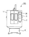
次に、図面を参照して本発明の実施例を説明し、発明の実施の形態の説明とする。(実施例)図1に示すように、工作機械100のベース8には切削屑の飛散を防止するためのスプラッシュカバー1が取付けられており、スプラッシュカバー1の前面には、表示手段に該当する液晶表示盤36や選択手段として機能するキーボード6等を有する操作パネル2が取付けられている。操作パネル2の内部には図6に示す制御装置3が収容されているが、制御装置3の構成、動作等は後述する。そして、スプラッシュカバー1の内側には、図2に示すマシニングセンタ7が収容されている。
【0017】
図2に示すように、マシニングセンタ7は、ベース8に固定されたコラム9を備え、コラム9の上面にはZモータ10としてのサーボモータが装着されている。コラム9の前面には垂直方向(Z軸方向)に沿ったガイドレール9a、9aが固定され、ガイドレール9aには加工ヘッド12が昇降スライド可能に装着されている。そして、Zモータ10の出力軸(図示しない)に連結された送りねじ11が加工ヘッド12に螺合されており、Zモータ10を正逆回転させると、加工ヘッド12がガイドレール9aに沿って昇降変位させられる。なお図2には示さないが、Zモータ10には、Z軸原点センサ24b(図6参照)としてのエンコーダが内蔵されている。
【0018】
加工ヘッド12には、加工軸に該当する主軸13が回転可能に装着されている。主軸13の下端部にはチャック(図示しない)が備えられており、このチャックを介して主軸13に工具14を着脱可能である。また、加工ヘッド12の上面には主軸モータ15としてのサーボモータが装着されており、主軸モータ15を回転させることで主軸13とともに工具14を回転駆動することができる。なお図2には示さないが、主軸モータ15には、主軸オリエンテーションセンサ24a(図6参照)としてのエンコーダが内蔵されている。
【0019】
加工ヘッド12の下方には、加工対象となるワーク(図示略)が載置されるワークテーブル16が配設されている。このワークテーブル16は、いずれもサーボモータであるXモータ17及びYモータ18(共に図2には示さない、図6参照)によって駆動され、左右方向(X軸方向)及び前後方向(Y軸方向)に水平移動する。これにより、ワークのX軸方向及びY軸方向の位置を変化させることができる。
【0020】
マシニングセンタ7には、主軸13に装着された工具14を別の工具14と交換するための、工具交換装置19が備わっている。工具交換装置19は、加工ヘッド12の側面側に配された工具マガジン20と加工ヘッド12の下面側に配された旋回部19a(図4参照)とを備えている。
【0021】
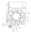
まず、図3を参照して、交換用の工具14を保持する工具マガジン20の構造を説明する。図3に示すように、工具マガジン20は、外殻となる外筒20bとその内側に配された内筒20aとを備え、内筒20aと外筒20bとの間には円環状の工具通路20cが形成されている。また、外筒20bの最下部は切り欠かれて、工具割出部20dとされている。
【0022】
工具通路20cには複数の工具ポット21が収納されており、各工具ポット21には、それぞれ1本の工具14を着脱可能である。各工具ポット21は、マガジンモータ22(図3には示さない、図6参照)に連結されており、マガジンモータ22を稼働させることで工具ポット21を工具通路20cに沿って回転移動させることができる。
【0023】
工具マガジン20の斜め下方には、工具14の欠損の有無を検出するための工具欠損センサ51が配されている。この工具欠損センサ51は、図3に実線で示す退避位置と1点鎖線で示す検出位置との間で揺動変位可能である。また、工具マガジン20には、工具ポット21と一体的に回転する工具検出板23が備わっている(図3には示さない、図6参照)。工具検出板23には、各工具ポット21に対応して複数の窓部が設けられており、各窓部に形成されているスリットの個数やスリットの周方向長さは、各窓部毎(すなわち各工具ポット21毎)に独特であり、互いに識別可能である。そして、図6に示されるように、工具検出板23を挟んで投光素子25aと受光素子25bとが互いに対面して配置されている。投光素子25aからの光が窓部を通過して受光素子25bに達すると受光素子25bの信号レベルが変化するので、受光素子25bの信号レベルを監視すれば、各工具ポット21の工具通路20c内での位置を判別できる。
【0024】
図3に示すように、工具ポット21が工具割出部20dの直上になる位置が割出位置であり、この割出位置の背後側には、エアシリンダ26(図3には示さない、図6参照)を駆動源とするポット回動機構(図示しない)が配されている。工具ポット21は、通常は工具14を水平方向に突出させる姿勢(後退姿勢)にあるが、割出位置にある工具ポット21だけは、ポット回動機構によって約90度回動させられて、工具割出部20dから突出して工具14を鉛直方向に垂下させる姿勢(前進姿勢、図3に2点鎖線で示す位置)に変位できる。また、ポット回動機構により、工具ポット21を前進姿勢から後退姿勢に戻すこともできる。なお、割出位置の付近には、工具ポット21が後退姿勢にあるとオンになるリミットスイッチがポット後退センサ27aとして設置され、工具ポット21が前進姿勢にあるとオンになるリミットスイッチがポット前進センサ27bとして設置されている(いずれも図3には示さない、図6参照)。
【0025】
また、工具ポット21が割出位置において後退姿勢にあるときに、工具欠損センサ51を退避位置から検出位置側に変位させれば、正常な工具14なら工具欠損センサ51が当たるが、例えば切り刃が欠落している場合には工具欠損センサ51が当たらないから、工具14の欠損の有無を検出できる。
【0026】
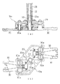
次に、図4を参照して旋回部19aの構造を説明する。図4に示すように、旋回部19aには、円筒状のアーム旋回軸28とアーム旋回軸28を貫通している中軸32との2つの駆動軸を備えており、アーム旋回軸28は回転及び昇降可能に加工ヘッド12に装着され、中軸32は回転可能に加工ヘッド12に装着されている。
【0027】
これらアーム旋回軸28及び中軸32は、図示を省略する運動伝達装置を介して、図2に示される工具交換モータ34に接続されており、工具交換モータ34によって駆動される。詳細には、運動伝達装置は、工具交換モータ34の回転力をアーム旋回軸28に伝達してこれを回転させるカム機構、工具交換モータ34の回転力を中軸32に伝達してこれを回転させるカム機構、工具交換モータ34の回転力を直線運動に変換してアーム旋回軸28に伝達してこれを昇降させるクランク機構などを備えており、工具交換モータ34の位相角に応じて、アーム旋回軸28の回転、中軸32の回転、アーム旋回軸28の昇降を行う。
【0028】
アーム旋回軸28の下端部には旋回アーム29が固着されており、旋回アーム29の両端部にはそれぞれ一対のフィンガ30、30が軸30aを中心にして揺動可能に取付けられている。フィンガ30、30の後端部の間には圧縮コイルスプリング31が介装されており、圧縮コイルスプリング31はフィンガ30、30の先端部を互いに近づけるを閉方向(矢印Aで示す方向)に付勢している。
【0029】
旋回アーム29には、カム軸33が回転可能に装着されており、カム軸33の外周部にはカム面33a、33aが設けられている。図示するように、各組の一方のフィンガ30の後端部がカム面33a相互間の段差部に落ち込んだ状態では、圧縮コイルスプリング31の付勢力により各組のフィンガ30、30先端部は閉じられる。しかし、カム軸33が図4(b)における反時計回り方向(矢印B方向)に回転するとカム面33aが各組の一方のフィンガ30の後端部を押圧するので、そのフィンガ30が圧縮コイルスプリング31の付勢力に抗して矢印Aと逆方向に揺動させられ、各組のフィンガ30、30先端部は開放される。
【0030】
カム軸33の上端部はアーム旋回軸28に内挿され、アーム旋回軸28の昇降すなわち旋回アーム29の昇降に伴って中軸32との軸方向位置を変化させる。一方、中軸32の下端部には狭隘な係合部32aが設けられており、カム軸33すなわち旋回アーム29が中軸32に対して相対的に上昇して上昇端(原点)になったときには、この係合部32aにカム軸33が係合しており、カム軸33を下降させると係合部32aとの係合が解除される。そして、カム軸33が係合部32aに係合しているときには、中軸32とカム軸33とが共回りする。
【0031】
なお、図4には示していないが、旋回アーム29が原点に上昇した際にオンされる近接センサ(例えばホール素子)がアームセンサ35aとして装着され、フィンガ30、30が開放状態にあるときにオンになる近接センサ(例えばホール素子)がフィンガセンサ35bとして装着されている(図6参照)。
【0032】
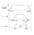
次に、図5を参照して、工具交換モータ34の位相角とアーム旋回軸28、中軸32、旋回アーム29及びフィンガ30の動作の関係を説明する。工具交換モータ34の位相角が0〜360度の範囲では(すなわち工具交換モータ34の稼働中は)、工具交換モータ34の回転力がカム機構により中軸32に伝達され、旋回アーム29が原点にあるときには、中軸32の係合部32aにカム軸33が係合しているので中軸32とカム軸33が共回りする。
【0033】
いま旋回アーム29が原点にあるとして、工具交換モータ34を稼働させたとする。工具交換モータ34の位相角が0〜12度の範囲では、カム面33aが各組の一方のフィンガ30の後端部を押圧していて、各組のフィンガ30、30の先端部は開放状態にある。工具交換モータ34の位相角が12度に達すると、各組の一方のフィンガ30の後端部がカム面33a間の段差部に落ち込みはじめ、フィンガ30、30が閉じ始める。そして、位相角50度では各組の一方のフィンガ30の後端部が完全に段差部に落ち込み、フィンガ30、30は閉状態になる。
【0034】
工具交換モータ34の位相角が65度になると、クランク機構が工具交換モータ34の回転力を直線運動に変換してアーム旋回軸28に伝達し、アーム旋回軸28とともに旋回アーム29を下降させる。この旋回アーム29の下降に伴って(位相角が80度以上になると)、中軸32とカム軸33の係合が解除される。そして、位相角が125度に達すると旋回アーム29は下降端になり、クランク機構によるアーム旋回軸28の下降駆動は終了する。
【0035】
一方、工具交換モータ34の位相角が100度に達すると、工具交換モータ34の回転力がカム機構を通じてアーム旋回軸28に伝達され、アーム旋回軸28と共に旋回アーム29が回転を開始する。この回転は、工具交換モータ34の位相角100〜180度の範囲で継続し、旋回アーム29もちょうど180度回転する。
【0036】
また、工具交換モータ34の位相角が235度になると、クランク機構によりアーム旋回軸28とともに旋回アーム29が上昇させられ、位相角295度で旋回アーム29が原点(上昇端)になり、クランク機構によるアーム旋回軸28の上昇駆動は終了する。なお、この上昇に伴って(位相角が270度以上になると)、中軸32とカム軸33の係合が復活する。
【0037】
そして、工具交換モータ34の位相角が310度になると、カム面33aが各組の一方のフィンガ30の後端部を押圧しはじめ、各組のフィンガ30、30先端部は開きはじめる。さらに、工具交換モータ34の位相角が348度に達すると、各組の一方のフィンガ30の後端部は完全にカム面33a上になって、フィンガ30、30は全開状態になる。
【0038】
このように、工具交換モータ34の位相角が0〜360度変化する1サイクル毎に、フィンガ30、30が閉じられ(50度)、中軸32とカム軸33の係合が解除され(80度)、旋回アーム29が下降し(125度)、旋回アーム29が180度回転し(100〜280度)、中軸32とカム軸33の係合が復活し(270度)、フィンガ30、30が開かれる(348度)。
【0039】
2組のフィンガ30、30の位置は、旋回アーム29の上昇時に閉じたときには、一方の組のフィンガ30、30にて主軸13に装着されている工具14を挟持し、他方の組が、工具割出部20dから垂下された(前進姿勢の)工具ポット21に保持されている工具14を挟持する位置に設定されているので、閉じたフィンガ30、30は、それぞれ主軸13に装着されている工具14と前進姿勢の工具ポット21に保持されている工具14を挟持する。
【0040】
続いて旋回アーム29が下降すると、2組のフィンガ30、30は工具14を挟持したまま下降して、それぞれの工具14を主軸13並びに工具ポット21から抜き取る。そこで旋回アーム29が180度回転することにより、主軸13に装着されていた工具14と工具ポット21に保持されていた工具14とが、互いに位置を入れ換える。
【0041】
そして、旋回アーム29が上昇すると、主軸13から取り外された工具14が工具ポット21に装着され、工具ポット21から取り外された工具14が主軸13に装着される。最後に2組のフィンガ30、30が開かれると、それぞれが工具14を解放する。
【0042】
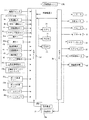
このように、工具交換モータ34の1サイクルで、工具14を交換することができる。次に、図6を参照して工作機械100の制御系について説明する。制御系の中枢となり、制御手段及びエラー判定手段として機能する制御装置3は、周知のCPU3a、ROM3b、RAM3c、入力インターフェース(入力I/F)3d、出力インターフェース(出力I/F)3e等から構成されるマイクロコンピュータである。
【0043】
入力インターフェース3dには、主軸オリエンテーションセンサ24a、Z軸原点センサ24b、ポット後退センサ27a、ポット前進センサ27b、アームセンサ35a、フィンガセンサ35b、受光素子25bが接続されている。これらは、工具交換装置19の可動部材の位置、姿勢、状態等を検出するためのセンシング手段に該当する。また、入力インターフェース3dには、工作機械100を起動させ、停止させるための起動スイッチ5、データやコマンド等を入力するための入力手段であり選択手段及び判定動作有無設定手段に該当するキーボード6も接続されている。キーボード6には、周知のアルファベットキー、テンキー、カーソルキーが備わっているほか、ファンクションキーとして、自動運転キー4a、MDI運転キー4b、手動運転キー4c、工具交換単動キー44、増キー39a、減キー39b、高速移動キー40、低速移動キー41、ステップ移動キー42、主軸回転キー43等が備わっている。
【0044】
一方、出力インターフェース3eには、Zモータ10、主軸モータ15、Xモータ17、Yモータ18、マガジンモータ22、エアシリンダ26、工具交換モータ34、液晶表示盤36、投光素子25aが接続されている。なお、投光素子25aは受光素子25bと共同してセンシング手段となる。
【0045】
次に、制御装置3が実行する処理を中心に、工具交換装置19の動作を説明する。起動スイッチ5がオンされると工作機械100が稼働を開始する。自動運転キー4aの操作により自動運転モードが選択されていれば、制御装置3は、例えば外部記憶装置(図示しない)から読み込んだ加工プログラムに従って、Zモータ10、主軸モータ15、Xモータ17、Yモータ18、マガジンモータ22、エアシリンダ26、工具交換モータ34等を制御する。これにより、ワークテーブル16にローディングされているワークに加工が施される。
【0046】
また、制御装置3は、加工の種類によって工具14の交換が必要になれば、工具の自動交換処理を実行する。その概略は次のとおりである。(1)ポット前進マガジンモータ22を制御して交換用の工具14を保持している工具ポット21を割出位置にさせ、エアシリンダ26を制御して割出位置の工具ポット21を前進姿勢に変位させる。(2)主軸オリエンテーション主軸モータ15を作動させて、主軸13を回転方向の原点にさせる。(3)アーム旋回工具交換モータ34を作動させて、フィンガ30、30を閉じて工具14を挟持し、旋回アーム29を下降させて両方の工具14を抜き取り、旋回アーム29を180度回転させて工具14の位置を入れ換え、旋回アーム29を上昇させて工具14を装着し、フィンガ30、30を開かせて工具14を解放するという、一連の工具交換動作を実行させる。(4)ポット後退エアシリンダ26を制御して、交換された工具14を保持している工具ポット21を、前進姿勢から後退姿勢に変位させる。
【0047】
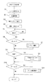
次に、上記の(1)ポット前進、(2)主軸オリエンテーション、(3)アーム旋回及び(4)ポット後退の各動作を、MDI運転モードで行う場合について、図7〜11を参照して説明する。ステップ実行キー4dが操作されると、制御装置3は、図7に示すMDI工具交換ルーチンを開始する。
【0048】
この処理では、まず主軸オリエンテーションセンサ24a、Z軸原点センサ24b、ポット後退センサ27a、ポット前進センサ27b、アームセンサ35a、フィンガセンサ35b及び受光素子25bからの信号を入力し(S1)、これらの信号に基づいて、割出位置の工具ポット21の姿勢、フィンガ30、30の状態等、各装置が正常位置にあるか異常位置にあるかを判別する(S2)。例えば割出位置の工具ポット21は後退姿勢(ポット後退センサ27aがオン)にあるか前進姿勢(ポット前進センサ27bがオン)にあれば正常であり、ポット後退センサ27a及びポット前進センサ27bがともにオフなら異常位置にあると判断し、旋回アーム29についてはフィンガセンサ35bがオン(フィンガ30、30が開放されている)なら正常であり、フィンガセンサ35bがオフなら異常位置にあると判断する。
【0049】
次に、制御装置3は液晶表示盤36に、図11に示すような選択入力のための画面を表示させる(S3)。この図11に示される画面では、ポット動作、主軸オリエンテーション及びアーム旋回が、本発明の動作ステップに該当している。また、図11においては、○印はカーソル位置を示し、カーソルキーで上下でき、それによってポット動作、主軸オリエンテーション、アーム旋回及びエラーチェックの各項目を選択できる。カーソル選択されている項目は、画面の下部に表示される(図11の例では「主軸オリエンテーション」)。
【0050】
このカーソル選択されている項目につき、テンキー入力で設定できる。なお、■印は未設定状態を示し、エラーチェックの項目はデフォルトで1(する)が設定されているが、変更可能である。続いて制御装置3は、各項目へのキー入力を受け付ける(S4)。具体的には、制御装置3は、液晶表示盤36に選択入力のための画面を表示させたまま待ち、テンキー入力されると、その数字を入力表示位置(図11の例では「主軸オリエンテーション→」の矢印先)に表示させ、確定キー(例えばリターンキー)が操作されると、■印に代えてその数字すなわち設定を表示させる。
【0051】
カーソル選択、テンキー入力及び確定キー入力を繰り返すことにより、複数の項目について一度に設定操作できる。ただし、主軸オリエンテーションとアーム旋回の両方を一度に設定することはできない。これは、主軸オリエンテーション(主軸13の回転)と旋回アーム29の旋回を並行して実行すると、フィンガ30、30により工具14を挟持したまま主軸13が回転したり、主軸13の回転中に工具14の着脱が行われると装置の破損等が発生するからである。
【0052】
しかし、ポット動作(工具ポット21の姿勢の変更)と主軸オリエンテーションは互いに干渉せず、並行して実行できるからから、この両方を一度に設定することは可能である。すなわち、相互に干渉しない動作ステップ同士なら、複数の動作ステップを同時に選択し、設定できる。
【0053】
また、エラーチェックは、装置の物理的な動作ではない(動作ステップではない)から、ポット前進、主軸オリエンテーション及びアーム旋回のいずれとでも、同時に設定できる。制御装置3は、ステップ実行キー4dが押されて動作ステップの実行が指示されると(S5:YES)、S4で選択された動作ステップの実行に移行する。
【0054】
すなわち、選択された動作ステップがポット動作なら(S6:YES)、ポット動作サブルーチン(S7)を実行し、選択された動作ステップが主軸オリエンテーションなら(S8:YES)、主軸オリエンテーションサブルーチン(S9)を実行し、選択された動作ステップがアーム旋回なら(S10:YES)、アーム旋回動作サブルーチン(S11)を実行する。
【0055】
図8に示すように、ポット動作サブルーチンでは、制御装置3は、上述のS4で選択されたポット動作が、0のポット前進か1のポット後退かを判断し(S21)、ポット後退なら(S21:NO)、上述のS4でのエラーチェックの設定が1(する)か0(しない)かを判断する(S22)。
【0056】
エラーチェックするなら(S22:YES)、工具ポット21が前進姿勢にある(ポット前進センサ27bがオンか)か否かを判断し(S24)、前進姿勢になっていなければ(S24:NO)、液晶表示盤36にエラー表示をする(S26)。工具ポット21が前進姿勢になっていれば(S24:YES)、割出位置の工具ポット21を後退姿勢に変位させる方向にポット回動機構を動作させる(S27)。これにより、工具ポット21が後退姿勢にさせられる。
【0057】
エラーチェックしないなら(S22:NO)、ポット前進センサ27bのオン、オフには無関係に、エアシリンダ26を制御して、割出位置の工具ポット21を後退姿勢に変位させる方向にポット回動機構を動作させる(S27)。このとき、工具ポット21が前進姿勢になっていれば後退姿勢にさせられるし、たとえ前進姿勢と後退姿勢の中間になっていても後退姿勢にさせられる。
【0058】
一方、S21で肯定判断(ポット前進)なら、S22と同様にエラーチェックをするかしないかを判断する(S23)。エラーチェックするなら(S23:YES)、工具ポット21が後退姿勢にある(ポット後退センサ27aがオンか)か否かを判断し(S25)、後退姿勢になっていなければ(S25:NO)、工具ポット21が異常位置にあると考えられ前進姿勢への変化は好ましくないから、液晶表示盤36にエラー表示をする(S28)。工具ポット21が後退姿勢になっていれば(S25:YES)、割出位置の工具ポット21を前進姿勢に変位させる方向にポット回動機構を動作させる(S29)。これにより、工具ポット21が前進姿勢にさせられる。
【0059】
エラーチェックしないなら(S23:NO)、ポット後退センサ27aのオン、オフには無関係に、エアシリンダ26を制御して、割出位置の工具ポット21を前進姿勢に変位させる方向にポット回動機構を動作させる(S29)。このとき、工具ポット21が後退姿勢になっていれば前進姿勢にさせられるし、たとえ前進姿勢と後退姿勢の中間になっていても前進姿勢にさせられる。
【0060】
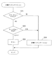
図9に示すように、主軸オリエンテーションサブルーチンでは、制御装置3は、まず上述のS4でのエラーチェックの設定が1(する)か0(しない)かを判断する(S31)。エラーチェックするなら(S31:YES)、フィンガセンサ35bがオンかオフか(すなわちフィンガ30、30が開放されているか否か)を判断する(S32)。フィンガセンサ35bがオフ(フィンガ30、30が開放されていない)なら、フィンガ30、30が主軸13に装着されている工具14を挟持している可能性があり、その状態での主軸13の回転は好ましくないから、液晶表示盤36にエラー表示をする(S33)。フィンガセンサ35bがオン(フィンガ30、30が開放されている)なら、主軸モータ15を稼働させて主軸13を回転方向の原点にさせる(S34)。この主軸13の回転位置は、主軸オリエンテーションセンサ24aの信号に基づいて判断される。
【0061】
一方、エラーチェックをしないなら(S31:NO)、フィンガセンサ35bのオン、オフには無関係に、主軸モータ15を稼働させて主軸13を回転方向の原点にさせる(S34)。図10に示すように、アーム旋回動作サブルーチンでは、制御装置3は、まず上述のS4でのエラーチェックの設定が1(する)か0(しない)かを判断する(S41)。
【0062】
エラーチェックするなら(S41:YES)、主軸オリエンテーションセンサ24aから取得した情報に基づいて、主軸13が回転方向の原点にあるか(主軸13のオリエンテーションがされているか)否かを判断する(S42)。主軸13が回転方向の原点になっていれば(S42:YES)、工具ポット21が前進姿勢になっているか否か(ポット前進センサ27bがオンか否か)を判断する(S43)。工具ポット21が前進姿勢になっていれば(S43:YES)、フィンガセンサ35bがオンかオフか(すなわちフィンガ30、30が開放されているか否か)を判断する(S44)。そして、フィンガ30、30が開放されていれば(S44:ON)、工具交換モータ34を作動させて、フィンガ30、30を閉じさせ、旋回アーム29を下降させ、旋回アーム29を180度回転させ、旋回アーム29を上昇させ、フィンガ30、30を開かせるという、アーム旋回動作を実行させる(S45)。
【0063】
しかし、主軸13が回転方向の原点にないとき(S42:NO)、工具ポット21が前進姿勢になっていないとき(S43:NO)或いはフィンガセンサ35bがオフのとき(S44:OFF)には、いずれもアーム旋回動作を実行すると干渉等の不具合が発生するおそれがあるので、液晶表示盤36にエラー表示をする(S46)。
【0064】
一方、エラーチェックしないなら(S41:NO)、主軸13の回転位置、工具ポット21の姿勢及びフィンガ30、30の開閉には無関係に、アーム旋回動作を実行させる(S46)。以上の通り、動作ステップ(ポット動作、主軸オリエンテーション、アーム旋回)が液晶表示盤36によって表示されているときに、カーソルキー、テンキー等を操作して動作ステップを選択し、その実行を指示すれば、制御装置3が、その選択された動作ステップを実行するための制御を行う。
【0065】
なお、ポット動作と主軸オリエンテーションは互いに干渉しないので、本実施例では、S4において両方の実行が入力された場合には、制御装置3は、ポット動作(図8参照)と主軸オリエンテーション(図9参照)とを並列処理する。このため、MDI運転モードにて工具交換を行う際に、オペレータはキーボード6の各種キーにて動作ステップを選択するだけで済み、覚え難いMコードを入力する必要はない。よって、MDI運転モードにて工具交換を行う際の操作性が向上する。
【0066】
しかも、同時に複数の動作ステップを選択することができ、その場合には、それら複数の動作ステップが並列的に実行されるから、オペレータは、複数の動作ステップを実行させたいときには、選択手段にて複数の動作ステップを選択すればよく、例えば1つの動作ステップを選択し、その終了を待ってから次の動作ステップを選択するといった、面倒な操作をする必要がなくなるから、この点でも操作性が向上する。
【0067】
そして、その動作ステップの実行に際してエラーチェックをするかしないかも併せて設定できる。これにより、例えば途中状態(異常位置)で停止していた場合には、エラーチェックをしない設定にて工具交換装置19を稼働させることで簡単に復旧することができる。また、正常な状態(正常位置)で停止しているときには、エラーチェックをする設定にて、工具交換動作をより安全に実行させることができる。
【0068】
以上、実施例に従って、本発明の実施の形態について説明したが、本発明はこのような実施例に限定されるものではなく、本発明の要旨を逸脱しない範囲でさまざまに実施できることは言うまでもない。
【図面の簡単な説明】
【図1】 実施例の工具交換装置を備える工作機械の正面図である。
【図2】 工作機械のマシニングセンタの斜視図である。
【図3】 工具交換装置の工具マガジンの構造の説明図である。
【図4】 工具交換装置の旋回部の説明図であり、(a)は断面図、(b)は下面図である。
【図5】 工具交換動作のタイミングチャートである。
【図6】 工具交換装置の制御系のブロック図である。
【図7】 工具交換装置の制御装置が実行するMDI工具交換処理のフローチャートである。
【図8】 工具交換装置の制御装置が実行するポット動作のフローチャートである。
【図9】 工具交換装置の制御装置が実行する主軸オリエンテーションのフローチャートである。
【図10】 工具交換装置の制御装置が実行するアーム旋回動作のフローチャートである。
【図11】 MDI工具交換に際しての選択入力のための画面表示の例示図である。
【符号の説明】
2…操作パネル(選択手段、判定動作有無設定手段)3…制御装置(制御手段、エラー判定手段)6…キーボード(選択手段、判定動作有無設定手段)13…主軸(加工軸)14…工具19…工具交換装置36…液晶表示盤(表示手段)[0001]
BACKGROUND OF THE INVENTION
The present invention relates to a tool changer for exchanging a tool mounted on a machining shaft and a tool stored in a tool magazine.
[0002]
[Prior art]
There is a tool changer for exchanging a tool mounted on a machining axis and a tool stored in a tool magazine, and is provided in a numerical control (NC) machining center, for example.
[0003]
Some of these tool changers have an MDI operation mode in which an NC program can be manually input and executed block by block in addition to an automatic operation mode in which tool change is automatically executed based on an NC program. is there.
[0004]
[Problems to be solved by the invention]
However, in order to execute tool change in the MDI operation mode, for example, an operation such as movement of the machining axis to the tool change position has to be input with an M code that is difficult to remember, and there is room for improvement in terms of usability. It was.
[0005]
The present invention has been made to solve the above-described problems, and an object of the present invention is to improve the operability when performing tool change in the MDI operation mode in the tool changer.
[0006]
[Means for Solving the Problems and Effects of the Invention]
The tool changer according to claim 1 for solving the above-mentioned problem is as follows.Driven by the spindle motorTool changer that exchanges the tool mounted on the machining axis and the tool stored in the tool magazineA tool pot mounted on the tool magazine with a variable position between the storage position and the exchange positionWhen,Tool pot driving means for displacing the tool pot between a storage position and an exchange position, a swivel arm capable of rotational displacement about a vertical axis and vertical displacement along the axis, and two 1 Phases of two sets of fingers attached to the swivel arm so as to be able to change between a closed state in which a tool can be clamped at the tip portion and an open state in which the clamped tool is released, and a tool change motor serving as a drive source A motion transmission device for rotating and raising and lowering the swivel arm according to an angle and opening and closing the finger, wherein the finger is moved from the open state to the closed state while the phase angle of the tool change motor changes by one cycle. A motion transmission device that lowers the swivel arm to rotate the swivel arm by a predetermined angle and raises the swivel arm to open the fingers, the spindle motor, and the tool pot drive means Control means for controlling the fine the tool exchange motorWhenA tool changer comprising:Becomes a component of tool change operationPot forward, backward movement, spindle orientation and arm rotationDisplay means for displaying each operation step, and for selecting one of the operation steps displayed by the display meansOperated byA selection means;Determination operation presence / absence setting means operated to set whether or not to perform error check for the operation step selected via the selection means, and error check for the operation step selected via the selection means If it is set through the determination operation presence / absence setting means, the operation stepError determination means that determines whether there is an error prior to execution of the operation, and if there is an error, does not allow execution of the operation stepAnd when the pot advance is selected via the selection means, the control means controls the tool pot drive means to store the tool pot unless execution is prohibited by the error determination means. When the pot forward movement for displacing from the position to the replacement position is executed and the pot backward movement is selected via the selection means, the tool pot drive means is controlled unless execution is prohibited by the error determination means. If the spindle orientation is selected through the selection means, the tool pot is displaced from the replacement position to the storage position, and the spindle orientation is selected through the selection means, unless execution is prohibited by the error determination means. Operate the spindle motor to execute the spindle orientation operation to change the rotational position of the machining axis to the position at the time of replacement. When the arm turning is selected via the selection means, unless the execution is prohibited by the error determination means, the tool change motor is operated to move the finger to the closed state, Executes an arm turning operation for lowering, rotating the turning arm by a predetermined angle, raising the turning arm, and displacing the finger to an open state.It is characterized by that.
[0007]
This tool changer becomes a component of the tool change operation by the display means.eachOperation step,In particular,Advances the pot to change the tool pot holding the tool from the storage position to the position at the time of replacement, spindle orientation to change the rotation position of the machining axis to the position at the time of replacement, and holds the tool on the machining axis and the tool pot Four operation steps: arm swiveling to replace the tool that has been changed, and pot retraction to change the tool pot from the position at the time of replacement to the storage positionIs displayed.
[0008]
When these operation steps are displayed by the display means, the selection meansIs manipulatedWhen any one of the displayed operation steps is selected, the control means performs control for executing the selected operation step. That is, when exchanging tools in the MDI operation mode, the operator only has to select one of the operation steps with the selection means, and there is no need to input an M code that is difficult to remember. Therefore, the operability when changing tools in the MDI operation mode is improved.
[0009]
By the way, the tool changer includes a sensor for detecting, for example, the position of the machining axis, the position of the tool pot, the open / close state of the finger for holding the tool, the position of the swivel arm for rotating the finger, and the like. It is normal. Then, it is determined whether or not there is an error such as interference based on the detection state of these sensors, and when there is an error, there is provided an error determination means that does not allow execution of a tool change operation or an operation step.
[0010]
However, for example, if the power is turned off during the tool change operation or the emergency stop button is pressed and stops in the middle (abnormal position), the error determination means that there is an error when restarting. Since the determination is made, the tool change operation cannot be continued or restored, resulting in operational inconvenience.
[0011]
On the other hand, if the error determination means is removed or stopped in order not to cause such inconvenience, the machine may be damaged due to interference or the like.
However, the tool changer according to claim 1A determination operation presence / absence setting unit operated to set whether or not to perform an error check on the operation step selected via the selection unit, and the error determination unit is an operation selected via the selection unit; If an error check is performed for a step and it is set via the determination operation presence / absence setting means, the presence / absence of an error is determined prior to execution of the operation step, and if there is an error, the operation step is not allowed to be executed It has become.
AndWhen the pot advance is selected via the selection means, the control means controls the tool pot drive means to displace the tool pot from the storage position to the replacement position unless execution is prohibited by the error determination means. When the operation is executed and the pot retreat is selected through the selection means, the pot for controlling the tool pot driving means to displace the tool pot from the replacement position to the storage position unless execution is prohibited by the error determination means. If the spindle orientation is selected via the selection means when the backward movement is executed, the spindle motor is operated to change the rotational position of the machining axis to the position at the time of replacement, unless execution is prohibited by the error determination means. When the orientation operation is executed and arm rotation is selected via the selection means, execution is prohibited by the error determination means Unless otherwise indicated, arm rotation is performed by operating the tool change motor to move the finger to the closed state, lower the swivel arm, rotate the swivel arm at a predetermined angle, raise the swivel arm, and move the finger to the open state. Execute the actionSo, for example, when stopping in the middle (abnormal position)Operate the judgment operation presence / absence setting means so that error check is not performed,It can be easily recovered by operating the tool changer without operating the error determination means. Further, when the vehicle is stopped in a normal state (normal position), the tool change operation can be executed more safely by operating the error determination means.
[0012]
Next, the tool changer according to
[0013]
Claim 2The tool changer according to claim 1.The same effects are produced in the same manner.
[0014]
Moreover, the control means of the tool changer according to
[0015]
[0016]
DETAILED DESCRIPTION OF THE INVENTION
Next, examples of the present invention will be described with reference to the drawings, and the embodiments of the present invention will be described. (Embodiment) As shown in FIG. 1, a splash cover 1 for preventing scattering of cutting waste is attached to a
[0017]
As shown in FIG. 2, the
[0018]
A
[0019]
A work table 16 on which a work (not shown) to be processed is placed is disposed below the
[0020]
The
[0021]
First, the structure of the
[0022]
A plurality of
[0023]
A
[0024]
As shown in FIG. 3, the position where the
[0025]
Further, when the
[0026]
Next, the structure of the turning
[0027]
The
[0028]
A
[0029]
A
[0030]
The upper end portion of the
[0031]
Although not shown in FIG. 4, when a proximity sensor (for example, a hall element) that is turned on when the
[0032]
Next, with reference to FIG. 5, the relationship between the phase angle of the
[0033]
Assume that the
[0034]
When the phase angle of the
[0035]
On the other hand, when the phase angle of the
[0036]
When the phase angle of the
[0037]
When the phase angle of the
[0038]
In this way, every cycle in which the phase angle of the
[0039]
When the positions of the two sets of
[0040]
Subsequently, when the
[0041]
When the
[0042]
In this way, the
[0043]
A
[0044]
On the other hand, a
[0045]
Next, the operation of the
[0046]
In addition, when the
[0047]
Next, with reference to FIGS. 7 to 11, a description will be given of the case where the operations (1) pot forward, (2) main shaft orientation, (3) arm rotation, and (4) pot reverse are performed in the MDI operation mode. To do. When the step execution key 4d is operated, the
[0048]
In this process, first, signals from the
[0049]
Next, the
[0050]
This item with the cursor selected can be set with the numeric keypad. The ■ mark indicates an unset state, and the error check item is set to 1 (default) by default, but can be changed. Subsequently, the
[0051]
By repeating cursor selection, numeric keypad input, and confirm key input, a plurality of items can be set at a time. However, both spindle orientation and arm rotation cannot be set at the same time. This is because when the spindle orientation (rotation of the spindle 13) and the turning of the turning
[0052]
However, since the pot operation (change in the attitude of the tool pot 21) and the spindle orientation do not interfere with each other and can be executed in parallel, both can be set at once. That is, if the operation steps do not interfere with each other, a plurality of operation steps can be simultaneously selected and set.
[0053]
Moreover, since the error check is not a physical operation of the apparatus (not an operation step), it can be set at the same time for any of pot forward, main shaft orientation, and arm rotation. When the step execution key 4d is pressed to instruct execution of the operation step (S5: YES), the
[0054]
That is, if the selected operation step is a pot operation (S6: YES), the pot operation subroutine (S7) is executed, and if the selected operation step is a spindle orientation (S8: YES), the spindle orientation subroutine (S9) is executed. If the selected operation step is arm rotation (S10: YES), an arm rotation operation subroutine (S11) is executed.
[0055]
As shown in FIG. 8, in the pot operation subroutine, the
[0056]
If an error check is to be made (S22: YES), it is determined whether or not the
[0057]
If the error check is not performed (S22: NO), the pot rotating mechanism is controlled in such a direction that the
[0058]
On the other hand, if an affirmative determination (pot advance) is made in S21, it is determined whether or not to perform an error check as in S22 (S23). If you check for errors (S23: YES), it is determined whether or not the
[0059]
If there is no error check (S23: NO), regardless of whether the
[0060]
As shown in FIG. 9, in the spindle orientation subroutine, the
[0061]
On the other hand, if the error check is not performed (S31: NO), the
[0062]
If an error check is to be made (S41: YES), based on the information acquired from the
[0063]
However, when the
[0064]
On the other hand, if the error check is not performed (S41: NO), the arm turning operation is executed regardless of the rotational position of the
[0065]
Since the pot operation and the spindle orientation do not interfere with each other, in this embodiment, when both executions are input in S4, the
[0066]
In addition, a plurality of operation steps can be selected at the same time. In this case, since the plurality of operation steps are executed in parallel, when the operator wants to execute a plurality of operation steps, the selection means It is only necessary to select a plurality of operation steps. For example, it is not necessary to perform a troublesome operation of selecting one operation step and waiting for the end of the operation step before selecting the next operation step. improves.
[0067]
It is also possible to set whether or not to perform an error check when executing the operation step. Thereby, for example, when the vehicle is stopped in the middle state (abnormal position), it can be easily restored by operating the
[0068]
As mentioned above, although embodiment of this invention was described according to the Example, this invention is not limited to such an Example, and it cannot be overemphasized that it can implement variously in the range which does not deviate from the summary of this invention.
[Brief description of the drawings]
FIG. 1 is a front view of a machine tool including a tool changer according to an embodiment.
FIG. 2 is a perspective view of a machining center of a machine tool.
FIG. 3 is an explanatory diagram of a structure of a tool magazine of the tool changer.
FIGS. 4A and 4B are explanatory views of a turning portion of the tool changer, in which FIG. 4A is a cross-sectional view, and FIG. 4B is a bottom view.
FIG. 5 is a timing chart of tool change operation.
FIG. 6 is a block diagram of a control system of the tool changer.
FIG. 7 is a flowchart of an MDI tool change process executed by the control device of the tool changer.
FIG. 8 is a flowchart of a pot operation executed by the control device of the tool changer.
FIG. 9 is a flowchart of spindle orientation executed by the control device of the tool changer.
FIG. 10 is a flowchart of an arm turning operation executed by the control device of the tool changer.
FIG. 11 is a view showing an example of a screen display for selection input when changing an MDI tool.
[Explanation of symbols]
2 ... Operation panel (selection means, determination operation presence / absence setting means) 3 ... Control device (control means, error determination means) 6 ... Keyboard (selection means, determination operation presence / absence setting means) 13 ... Main axis (machining axis) 14 ...
Claims (2)
収納位置と交換位置との間で位置を可変に前記工具マガジンに装着された工具ポットと、
前記工具ポットを収納位置と交換位置とに変位させる工具ポット駆動手段と、
上下方向の軸を中心にしての回転変位と前記軸に沿っての昇降変位とが可能な旋回アームと、
2本1組で先端部にて工具を挟持可能な閉状態と前記挟持した工具を解放する開状態とに変化可能に前記旋回アームに取り付けられた2組のフィンガと、
駆動源となる工具交換モータの位相角に応じて前記旋回アームを回転並びに昇降させ、また前記フィンガを開閉させる運動伝達装置であって、前記工具交換モータの位相角が1サイクル分変化する間に前記フィンガを前記開状態から前記閉状態にし、旋回アームを下降させて旋回アームを所定角度回転させ、旋回アームを上昇させてフィンガを開状態にする運動伝達装置と、
前記主軸モータ、前記工具ポット駆動手段及び前記工具交換モータを制御する制御手段と
を備える工具交換装置において、
工具交換動作の構成要素となるポット前進、後退動作、主軸オリエンテーション及びアーム旋回の各動作ステップを表示する表示手段と、
該表示手段により表示された動作ステップのいずれかを選択するために操作される選択手段と、
前記選択手段を介して選択された前記動作ステップについてエラーチェックを行うか否かを設定するために操作される判定動作有無設定手段と、
前記選択手段を介して選択された前記動作ステップについてエラーチェックを行うと前記判定動作有無設定手段を介して設定されていれば、当該動作ステップの実行に先だってエラーの有無を判定し、エラーが有る場合には該動作ステップの実行を許さないエラー判定手段とを備え、
前記制御手段は、
前記選択手段を介してポット前進が選択されると、前記エラー判定手段によって実行が禁止されていない限り、前記工具ポット駆動手段を制御して前記工具ポットを前記収納位置から前記交換位置に変位させるポット前進動作を実行させ、
前記選択手段を介してポット後退が選択されると、前記エラー判定手段によって実行が禁止されていない限り、前記工具ポット駆動手段を制御して前記工具ポットを前記交換位置から前記収納位置に変位させるポット後退動作を実行させ、
前記選択手段を介して主軸オリエンテーションが選択されると、前記エラー判定手段によって実行が禁止されていない限り、前記主軸モータを作動させて前記加工軸の回転位置を交換時の位置にする主軸オリエンテーション動作を実行させ、
前記選択手段を介してアーム旋回が選択されると、前記エラー判定手段によって実行が禁止されていない限り、前記工具交換モータを作動させることにより前記フィンガの前記閉状態への変位、前記旋回アームの下降、前記旋回アームの所定角度回転、前記旋回アームの上昇及び前記フィンガの開状態への変位を行わせるアーム旋回動作を実行させる
ことを特徴とする工具交換装置。A tool changer for exchanging a tool mounted on a machining axis rotated by a spindle motor and a tool stored in a tool magazine ;
A tool pot mounted on the tool magazine with a variable position between a storage position and an exchange position ;
Tool pot driving means for displacing the tool pot between a storage position and an exchange position;
A swivel arm capable of rotational displacement about a vertical axis and vertical displacement along the axis;
Two sets of fingers attached to the swivel arm so as to be able to change between a closed state in which a tool can be clamped at the tip by one set of two and an open state in which the clamped tool is released;
A motion transmission device that rotates and raises and lowers the swivel arm according to a phase angle of a tool change motor serving as a drive source, and opens and closes the finger, while the phase angle of the tool change motor changes by one cycle. A motion transmission device that changes the finger from the open state to the closed state, lowers the swing arm to rotate the swing arm by a predetermined angle, and raises the swing arm to open the finger;
Control means for controlling the spindle motor, the tool pot drive means and the tool change motor ;
A tool changer comprising:
Display means for displaying each operation step of pot forward movement, backward movement, spindle orientation and arm rotation, which is a component of the tool change operation;
Selection means operated to select any of the operation steps displayed by the display means;
Determination operation presence / absence setting means operated to set whether or not to perform an error check for the operation step selected via the selection means;
If an error check is performed on the operation step selected via the selection means, if it is set via the determination operation presence / absence setting means, the presence / absence of an error is determined prior to execution of the operation step , and there is an error. An error determination means that does not allow execution of the operation step in the case ,
The control means includes
When pot advance is selected via the selection means, the tool pot driving means is controlled to displace the tool pot from the storage position to the replacement position unless execution is prohibited by the error determination means. Execute the pot forward movement,
When pot retraction is selected via the selection means, the tool pot driving means is controlled to displace the tool pot from the replacement position to the storage position unless execution is prohibited by the error determination means. Execute the pot backward movement,
When the spindle orientation is selected via the selection means, unless the execution is prohibited by the error determination means, the spindle motor operates the spindle motor to set the rotational position of the machining axis to the position at the time of replacement. And execute
When the arm turning is selected via the selection means, unless the execution is prohibited by the error determination means, the tool change motor is operated to move the finger to the closed state, A tool changer for performing an arm turning operation for lowering, rotating the turning arm by a predetermined angle, raising the turning arm, and moving the finger to an open state .
前記制御手段は、
前記選択手段を介して選択された前記動作ステップが複数であって互いに干渉しないときには、それら複数の動作ステップを並列的に実行するための制御を行う
ことを特徴とする工具交換装置。 The tool changer according to claim 1, wherein
The control means includes
A tool changer characterized by performing control for executing the plurality of operation steps in parallel when there are a plurality of the operation steps selected through the selection means and do not interfere with each other. .
Priority Applications (1)
| Application Number | Priority Date | Filing Date | Title |
|---|---|---|---|
| JP00123499A JP4374635B2 (en) | 1999-01-06 | 1999-01-06 | Tool changer |
Applications Claiming Priority (1)
| Application Number | Priority Date | Filing Date | Title |
|---|---|---|---|
| JP00123499A JP4374635B2 (en) | 1999-01-06 | 1999-01-06 | Tool changer |
Publications (2)
| Publication Number | Publication Date |
|---|---|
| JP2000198039A JP2000198039A (en) | 2000-07-18 |
| JP4374635B2 true JP4374635B2 (en) | 2009-12-02 |
Family
ID=11495787
Family Applications (1)
| Application Number | Title | Priority Date | Filing Date |
|---|---|---|---|
| JP00123499A Expired - Fee Related JP4374635B2 (en) | 1999-01-06 | 1999-01-06 | Tool changer |
Country Status (1)
| Country | Link |
|---|---|
| JP (1) | JP4374635B2 (en) |
Families Citing this family (4)
| Publication number | Priority date | Publication date | Assignee | Title |
|---|---|---|---|---|
| JP6322896B2 (en) * | 2013-03-28 | 2018-05-16 | ブラザー工業株式会社 | Machine Tools |
| JP6078413B2 (en) * | 2013-04-30 | 2017-02-08 | Dmg森精機株式会社 | Tool changing method and machine tool |
| JP7014115B2 (en) * | 2018-09-26 | 2022-02-01 | ブラザー工業株式会社 | Numerical control device and control method |
| JP6975195B2 (en) * | 2019-04-04 | 2021-12-01 | ファナック株式会社 | Machine Tools |
-
1999
- 1999-01-06 JP JP00123499A patent/JP4374635B2/en not_active Expired - Fee Related
Also Published As
| Publication number | Publication date |
|---|---|
| JP2000198039A (en) | 2000-07-18 |
Similar Documents
| Publication | Publication Date | Title |
|---|---|---|
| JP5556656B2 (en) | Numerical control machine tool, control program, and storage medium | |
| US7899574B2 (en) | Machine-tool controller | |
| JPS5820741B2 (en) | Machining center tool change mechanism | |
| JP2000190113A (en) | Method and apparatus for controlling electric chuck | |
| JP5187518B2 (en) | Numerically controlled machine tool | |
| JPH05305553A (en) | Tool breakage detection method | |
| JP4374635B2 (en) | Tool changer | |
| JP2005028522A (en) | Machine tool and method for detecting breakage of machine tool | |
| JP4706445B2 (en) | Machine tool and its tool change method | |
| JP4433968B2 (en) | Machine tool and tool change method for machine tool | |
| JP2006106849A (en) | Machine Tools | |
| JP6970844B1 (en) | Machine Tools | |
| JP4443380B2 (en) | Tool magazine apparatus and vertical machining center equipped with the same | |
| JP5110021B2 (en) | Numerical control device for machine tools | |
| JPH0596433A (en) | Manual tool exchange method in machining center | |
| JPH11114756A (en) | Machine Tools | |
| JPH1199447A (en) | Tool changer | |
| JP3423201B2 (en) | Numerical control unit | |
| JP2008097193A (en) | Machine tool controller | |
| JPH048445A (en) | Numerical control system with automatic tool changing function | |
| JP2007148873A (en) | Numerical controller | |
| JP4710294B2 (en) | Machine tool and method for controlling machine tool | |
| JP2004314236A (en) | Machine tool and tool change method of machine tool | |
| JPH05313718A (en) | Numerical control device | |
| JP5035601B2 (en) | NC machine tool |
Legal Events
| Date | Code | Title | Description |
|---|---|---|---|
| A621 | Written request for application examination |
Free format text: JAPANESE INTERMEDIATE CODE: A621 Effective date: 20050318 |
|
| A977 | Report on retrieval |
Free format text: JAPANESE INTERMEDIATE CODE: A971007 Effective date: 20080403 |
|
| A131 | Notification of reasons for refusal |
Free format text: JAPANESE INTERMEDIATE CODE: A131 Effective date: 20080603 |
|
| A521 | Written amendment |
Free format text: JAPANESE INTERMEDIATE CODE: A523 Effective date: 20080725 |
|
| TRDD | Decision of grant or rejection written | ||
| A01 | Written decision to grant a patent or to grant a registration (utility model) |
Free format text: JAPANESE INTERMEDIATE CODE: A01 Effective date: 20090818 |
|
| A01 | Written decision to grant a patent or to grant a registration (utility model) |
Free format text: JAPANESE INTERMEDIATE CODE: A01 |
|
| A61 | First payment of annual fees (during grant procedure) |
Free format text: JAPANESE INTERMEDIATE CODE: A61 Effective date: 20090831 |
|
| R150 | Certificate of patent or registration of utility model |
Free format text: JAPANESE INTERMEDIATE CODE: R150 |
|
| FPAY | Renewal fee payment (event date is renewal date of database) |
Free format text: PAYMENT UNTIL: 20120918 Year of fee payment: 3 |
|
| FPAY | Renewal fee payment (event date is renewal date of database) |
Free format text: PAYMENT UNTIL: 20130918 Year of fee payment: 4 |
|
| LAPS | Cancellation because of no payment of annual fees |