JP4374481B2 - Respiratory gas sensor - Google Patents
Respiratory gas sensor Download PDFInfo
- Publication number
- JP4374481B2 JP4374481B2 JP2000139679A JP2000139679A JP4374481B2 JP 4374481 B2 JP4374481 B2 JP 4374481B2 JP 2000139679 A JP2000139679 A JP 2000139679A JP 2000139679 A JP2000139679 A JP 2000139679A JP 4374481 B2 JP4374481 B2 JP 4374481B2
- Authority
- JP
- Japan
- Prior art keywords
- tubular member
- gas sensor
- respiratory gas
- adapter
- flow path
- Prior art date
- Legal status (The legal status is an assumption and is not a legal conclusion. Google has not performed a legal analysis and makes no representation as to the accuracy of the status listed.)
- Expired - Fee Related
Links
Images


Description
【0001】
【発明の属する技術分野】
本発明は、生体の呼吸気のガス濃度を計測するか、または呼吸の有無を判定するときに用いられる呼吸気ガスセンサに係り、特に比較的換気量の少ない生体を対象とした場合に好適な呼吸気ガスセンサ(以下、単にセンサと称する)に関する。
【0002】
【従来の技術】
生体の呼気中のCO2 などのガス濃度を測定する装置としては、本出願人が提案し実公平4−48534号公報により開示されたセンサが公知である。このセンサの構成を図14乃至図16に示す。図14は正面図、図15は平面図、図16は本センサの作用を示す要部拡大断面図である。
【0003】
図中センサ1は管状部材であるフロースルーセル2と、フロースルーセル2の軸に対しほぼ直角の方向の外周に設けられた赤外線光源部3と赤外線検出部4とにより構成されている。これらの赤外線光源部3と赤外線検出部4とは同一光軸上に設けられており、フロースルーセル2の外壁に気密に形成された透光窓5,6を介して、赤外線がフロースルーセル2内を軸に対してほぼ直角な方向に通過するようになっている。そしてフロースルーセル2内を流れる呼気中のCO2 などのガスによって吸収された波長の光のみを赤外線検出部4によって検出し、公知の手段によってガス濃度を測定する。
【0004】
上記のように構成されたセンサ1によってガス濃度を測定する場合、フロースルーセンサの内容積が大きいと特に新生児などのように換気量が少ない生体では死腔量が大きすぎて使用できない。この問題を解決するために前述した提案では図14乃至図16に示すように、フロースルーセル2の内周面に嵌合し透光窓5,6と整合する位置に貫通孔7aが形成された管状のアダプタ7を設けた。この構成によると、センサ1の内容積が大幅に減少し、死腔量が減少する。この結果、換気量の少ない新生児などの呼気中のCO2 などのガス濃度を効率よく計測することができる。
【0005】
【発明が解決しようとする課題】
しかしながら、上記のように構成された従来のセンサによると、呼吸ガスはアダプタ7の中心の内径の小さい貫通孔7b内を流れ、赤外線光源部3から発する検出光の中央部分のみしか呼吸ガス中を通過しない。このため赤外線検出部4が検出する検出光の光量が減少し、測定精度が低下する可能性があった。
【0006】
また、呼吸ガスは通常100%に近い湿度を有しているため、10数回測定を繰り返すとアダプタ7の透光窓5,6に対向して形成された貫通孔7a内に、図12に示すように水滴8が溜まって流出しない状態となる。この結果、水滴8が検出光を遮ぎってしまい、測定誤差を生ずるおそれもあった。
【0007】
本発明はこのような状況に鑑なみてなされたもので、換気量の少ない生体の呼吸気ガス濃度などを、水滴の影響を受けることなく、効率よく高精度で計測することのできる簡単な構造の呼吸気ガスセンサを提供することを目的とする。
【0008】
【課題を解決するための手段】
上記目的を達成するために、請求項1に記載の本発明は、管状部材で形成された流路内を流れるガス中に外部から検出光を透過させるための一対の透光窓を、前記管状部材の周壁に気密に設け、前記管状部材の内周面に嵌合し、前記透光窓と整合する位置に貫通孔が形成されたアダプタを設けた呼吸気ガスセンサにおいて、前記アダプタの外周と前記管状部材との間にスリットを軸方向に貫通して設けて、前記ガス流路を形成し、前記スリットは前記透光窓に近接する位置で前記ガスが前記透光窓全体に沿って流れるように形成されていることを特徴とする。
【0009】
請求項2に記載の呼吸気ガスセンサは、前記アダプタが前記透光窓の軸方向の両側に分割されたことを特徴とする。
【0010】
請求項3に記載の呼吸気ガスセンサは、前記分割されたアダプタが、前記管状部材内に固定されたことを特徴とする。
【0011】
請求項4に記載の呼吸気ガスセンサは、前記分割されたアダプタが、前記管状部材内で着脱可能に連結されたことを特徴とする。
【0013】
請求項5に記載の呼吸気ガスセンサは、内部にガスの流路を設けられた管状部材を備え、その流路内を流れるガス中に外部から検出光を透過させるため前記管状部材の周壁に気密に一対の透光窓を設け、前記管状部材は内部に、前記流路を2つに分ける仕切り部を備え、 前記仕切り部は前記透光窓の一方からの光を他方に通す貫通孔を有し、前記仕切り部によって分けられた流路は、前記透光窓にそれぞれに沿うようにされ、前記透光窓に接する箇所では前記ガスが前記透光窓全体に沿って流れるように形成されたことを特徴とする。
【0014】
請求項6に記載の呼吸気ガスセンサは、請求項1乃至請求項5のいずれか1つにおけるセンサの前記透光窓の内面に防曇膜を設けたことを特徴とする。
【0015】
請求項1に記載の本発明によると、前記アダプタの外周と前記管状部材との間にスリットを軸方向に貫通して設けて、前記ガス流路を形成し、前記スリットは前記透光窓に近接する位置で前記ガスが前記透光窓全体に沿って流れるように形成されているので、赤外線光源部から発し透光窓を通過する検出光全体がガス流路を通過する呼吸ガスを照射することができ、ガス濃度を効率よく高精度で計測することができる。また透光窓に近接してガス流路が形成されているので、透光窓内面に水滴が溜ることはない。
【0016】
請求項2乃至4に記載の本発明によると、アダプタが分割されているので成形が容易となる。この場合、分割されたアダプタを管状部材内で固定しても着脱可能に連結してもよいが、着脱可能とすることにより使用後アダプタを管状部材から取り出し、洗浄滅菌して再利用することができる。
【0018】
請求項5に記載の本発明によると、請求項1の発明の作用と同様の作用を得られる。
【0019】
請求項6に記載の本発明によると、透光窓の内面に防曇膜を設けたので、ガス流路内を通過する呼吸ガスの湿気により透光窓の内面が曇ることを防止できる。
【0020】
【発明の実施の形態】
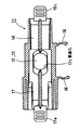
以下、本発明の呼吸気ガスセンサの第1の実施の形態を図面を参照して説明する。図1はフロースルーセルにアダプタを取り付けた状態を示す縦断面図、図2は図1の横断面図、図3は図2の左側面図、図4は図2の右側面図、図5,図6,図7はそれぞれ図1のA−A線、B−B線、C−C線断面図、図8は図1の分解正面図、図9は図2の分解上面図である。
【0021】
管状部材であるフロースルーセル11の中央部は縮径されており、軸方向に対して平行にかつ対称の位置に平行面11aが形成されている。平行面11aの中心には従来例と同様な透光窓12,13が気密に設けられている。また透光窓12,13の内面にはそれぞれ防曇膜14,15が形成されている。なお平行面11aの少くとも軸方向片側には、外周側に突出して赤外線光源部と赤外線検出部を保持する保持部16が一体に形成されている。透光窓12,13の外周には図示しないが従来例と同様に赤外線光源部と赤外線検出部とが配置されている。
【0022】
フロースルーセル11中には左右一対のアダプタ17,18が嵌合されている。図中左側のアダプタ17の軸方向の中央部には、フロースルーセル11の内周面に当接し、平行面11aの軸方向内面の左側に当接する円筒状の鍔部17aが一体に形成されている。鍔部17aの図中右側には中心軸に沿って板状部17bが一体に形成されており、板状部17bの両面は所定幅の間隔を介して平行面11aに平行に対向している。また板状部17bには透光窓12,13と同軸上に貫通孔17cが形成されている。さらに鍔部17aには板状部17bの両面に平行にスリット17dが形成されており、板状部17bの両面と平行面11aとの間に形成された間隙と連通したガス流路となっている。
【0023】
図中右側のアダプタ18はほぼ円柱状に形成されており、外周はフロースルーセル11の平行面11aの右側内周面に当接している。またアダプタ18の左側端面は平行面11aの軸方向内面の右側に当接している。アダプタ18の外周には軸方向に平行に一対のスリット18aが貫通して形成されている。スリット18aはアダプタ17の板状部17bとフロースルーセル11の平行面11aとの間に形成された間隙(スリット17f)と連通しており、スリット17dとも連通したガス流路となっている。
【0024】
アダプタ17の板状部17bの内側の一端には、図8,9に示すように軸方向に平行にロック爪19が一体に設けられており、ロック爪19の先端には山型の係止部19aが形成されている。一方アダプタ18には係止孔18bが形成されており、アダプタ17,18がフロースルーセル11内の所定の位置に嵌合装着されたとき、ロック爪19の係止部19aが係止孔18bに係合しロックされるようになっている。なお係止部19aは両側が斜面となっている山型に形成されているため、アダプタ17,18の外側の端面に突出して設けられたツマミ17e,18cを把持して強く外側に引張れば、容易にロックを解除できるようになっている。
【0025】
本実施の形態によれば、透光窓12,13全面とアダプタ17の板状部17bとの間に形成されたスリット状のガス流路を呼吸気ガスが流れるため、センサの内容積を小さくし死腔量を減らすことができる。この結果、小児などの換気量の少ない呼吸気ガス濃度を簡単な構造で効率よく高精度で計測することができる。またガス流路が透光窓12,13とアダプタ17の板状部17bとの間でスリット状に形成されるので、呼吸気ガス中の水分が水滴となって透光窓12,13の内面に溜まることがなく、ガス濃度計測の精度を向上させることができる。
【0026】
上記実施の形態ではアダプタ17,18を着脱可能とし、計測センサを滅菌して再使用可能としているが、アダプタ17,18をフロースルーセル11内に固定し、使い捨てとしてもよい。また、計測としてはガス濃度計測に適するが、呼吸気ガスの有無により、呼吸の有無を判定することもできる。
【0027】
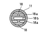
次に本発明の第2の実施の形態を説明する。この例は、第1の実施の形態のアダプタがフローセル内に固定されたと同じ形態であって、一体的に形成されたものである。図10はフロースルーセルの外観を示す斜視図、図11は図10の一部切り欠き図、図12は図10のX−X線断面図、図13は図10のY−Y線断面図である。
【0028】
図10に示すように管状部材であるフロースルーセル21の中央部22は箱型であり、1対の平行面22aが形成されている。平行面22aの中心には従来例と同様な1対の透光窓23が設けられている。透光窓23の内側には防曇膜24が張られ、これによって透光窓23は気密にされている。中央部22の側部の両端には、外周側に突出して赤外線光源部と赤外線検出部を保持する1対の保持部26が一体に形成されている。1対の透光窓23の外周には図示しないが従来例と同様に赤外線光源部と赤外線検出部とが配置されている。
【0029】
図11乃至図13に示すように、フロースルーセル21の内部は板状の仕切り部27によって流路が2つに分けられている。仕切り部27には透光窓23と同じ光軸上に貫通孔29が形成されている。透光窓23と仕切り部27との間にはスリット状の流路31、32が形成されている。ここで、流路31、32は透光窓23にそれぞれに沿うようにされ、ガスが透光窓23全体に沿って流れるように形成されている。
【0030】
本実施の形態によれば、透光窓23の全面と仕切り部27との間に形成されたスリット状の流路31、32を呼吸気ガスが流れるため、第1の実施の形態と同様、センサの内容積を小さくし死腔量を減らすことができ、ガス中の水分が水滴となって透光窓23の内面に溜ることがなくなる。さらに本実施の形態によれば、アダプタが不要であるので、製造が容易であるとともに使用の際の作業が簡単である。また、安価に製造できるので、使い捨てとすることもできる。
【0031】
【発明の効果】
以上説明したように、本発明の呼吸気ガスセンサによれば、計測センサの内容積を小さくして死腔量を減らすことができる。この結果、小児などの換気量の少ない呼吸気ガス濃度を簡単な構造で効率よく高精度で計測することができる。また透光窓全体の表面に沿って呼吸気ガスが通過するので、呼吸気ガス中の水分が水滴となって透光窓内に溜ることがなく、ガス濃度計測の精度を向上させることができる。
【図面の簡単な説明】
【図1】本発明の呼吸気ガスセンサの一実施の形態のフロースルーセルにアダプタを取り付けた状態を示す縦断面図。
【図2】図1の横断面図。
【図3】図2の左側面図。
【図4】図2の右側面図。
【図5】図1のA−A線断面図。
【図6】図1のB−B線断面図。
【図7】図1のC−C線断面図。
【図8】図1の分解側面図。
【図9】図2の分解上面図。
【図10】第2の実施の形態におけるフロースルーセルの外観を示す斜視図。
【図11】図10の一部切り欠き図。
【図12】図10のX−X線断面図。
【図13】図10のY−Y線断面図。
【図14】従来の呼吸気ガスセンサの一例の構成を示す表面図。
【図15】図14の平面図。
【図16】図14の要部拡大断面図。
【符号の説明】
11、21 フロースルーセル(管状部材) 12,13、23 透光窓
14,15,24 防曇膜 17,18 アダプタ
17d,18a スリット 17c、29 貫通孔
27 仕切り部[0001]
BACKGROUND OF THE INVENTION
The present invention relates to a respiratory gas sensor used when measuring the gas concentration of respiratory air in a living body or determining the presence or absence of breathing, and particularly suitable for a living body with a relatively small ventilation amount. The present invention relates to a gas gas sensor (hereinafter simply referred to as a sensor).
[0002]
[Prior art]
As an apparatus for measuring the concentration of gas such as CO2 in the exhalation of a living body, a sensor proposed by the present applicant and disclosed in Japanese Utility Model Publication No. 4-48534 is known. The structure of this sensor is shown in FIGS. 14 is a front view, FIG. 15 is a plan view, and FIG. 16 is an enlarged cross-sectional view of the main part showing the operation of the present sensor.
[0003]
In the figure, the sensor 1 includes a flow-through
[0004]
When the gas concentration is measured by the sensor 1 configured as described above, when the internal volume of the flow-through sensor is large, a dead space is too large for a living body with a small ventilation, such as a newborn, and cannot be used. In order to solve this problem, in the above-mentioned proposal, as shown in FIGS. 14 to 16, a
[0005]
[Problems to be solved by the invention]
However, according to the conventional sensor configured as described above, the respiratory gas flows in the
[0006]
In addition, since the breathing gas usually has a humidity close to 100%, when the measurement is repeated 10 or more times, in the
[0007]
The present invention was made in view of such a situation, and has a simple structure that can efficiently and accurately measure the respiratory gas concentration of a living body with a small amount of ventilation without being affected by water droplets. An object of the present invention is to provide a respiratory gas sensor.
[0008]
[Means for Solving the Problems]
In order to achieve the above object, the present invention according to claim 1 is characterized in that a pair of light-transmitting windows for allowing detection light to transmit from the outside into a gas flowing in a flow path formed by a tubular member is provided in the tubular shape. In a respiratory gas sensor provided with an adapter provided in an airtight manner on the peripheral wall of the member, fitted to the inner peripheral surface of the tubular member, and provided with an adapter in which a through hole is formed at a position aligned with the translucent window, the outer periphery of the adapter and the A slit is provided through the tubular member in the axial direction to form the gas flow path, and the gas flows along the entire light-transmitting window at a position close to the light-transmitting window. It is characterized by being formed .
[0009]
The respiratory gas sensor according to
[0010]
The respiratory gas sensor according to claim 3 is characterized in that the divided adapter is fixed in the tubular member.
[0011]
The respiratory gas sensor according to a fourth aspect is characterized in that the divided adapter is detachably connected in the tubular member.
[0013]
The respiratory gas sensor according to
[0014]
Respiratory gas sensor according to
[0015]
According to the first aspect of the present invention, a slit is provided in an axial direction between the outer periphery of the adapter and the tubular member to form the gas flow path, and the slit is formed in the translucent window. Since the gas is formed so as to flow along the entire light-transmitting window at a close position, the entire detection light emitted from the infrared light source section and passing through the light-transmitting window irradiates the breathing gas passing through the gas flow path. Therefore, the gas concentration can be measured efficiently and with high accuracy. Further, since the gas flow path is formed in the vicinity of the light transmission window, water droplets do not accumulate on the inner surface of the light transmission window.
[0016]
According to the second to fourth aspects of the present invention, since the adapter is divided, molding becomes easy. In this case, the divided adapter may be fixed in the tubular member or detachably connected. However, by making the adapter detachable, the adapter can be taken out from the tubular member after use, washed and sterilized, and reused. it can.
[0018]
According to the fifth aspect of the present invention, the same action as that of the first aspect of the invention can be obtained.
[0019]
According to the sixth aspect of the present invention, since the anti-fogging film is provided on the inner surface of the light transmission window, it is possible to prevent the inner surface of the light transmission window from being fogged by the moisture of the breathing gas passing through the gas flow path.
[0020]
DETAILED DESCRIPTION OF THE INVENTION
Hereinafter, a first embodiment of a respiratory gas sensor of the present invention will be described with reference to the drawings. 1 is a longitudinal sectional view showing a state where an adapter is attached to a flow-through cell, FIG. 2 is a transverse sectional view of FIG. 1, FIG. 3 is a left side view of FIG. 2, FIG. 4 is a right side view of FIG. 6 and 7 are cross-sectional views taken along lines AA, BB, and CC, respectively, FIG. 8 is an exploded front view of FIG. 1, and FIG. 9 is an exploded top view of FIG.
[0021]
The central portion of the flow-through
[0022]
In the flow-through
[0023]
The
[0024]
As shown in FIGS. 8 and 9, a
[0025]
According to the present embodiment, since the respiratory gas flows through the slit-like gas flow path formed between the entire surface of the
[0026]
In the above embodiment, the
[0027]
Next, a second embodiment of the present invention will be described. This example is the same form as the adapter of the first embodiment fixed in the flow cell, and is integrally formed. 10 is a perspective view showing the appearance of the flow-through cell, FIG. 11 is a partially cutaway view of FIG. 10, FIG. 12 is a sectional view taken along line XX of FIG. 10, and FIG. 13 is a sectional view taken along line YY of FIG. It is.
[0028]
As shown in FIG. 10, the
[0029]
As shown in FIGS. 11 to 13, the flow-through
[0030]
According to the present embodiment, since the respiratory gas flows through the slit-shaped
[0031]
【The invention's effect】
As described above, according to the respiratory gas sensor of the present invention, the dead volume can be reduced by reducing the internal volume of the measurement sensor. As a result, it is possible to efficiently and accurately measure the respiratory gas concentration of a child or the like with a small amount of ventilation with a simple structure. In addition, since the breathing gas passes along the entire surface of the light transmission window, moisture in the breathing gas does not become water droplets and accumulate in the light transmission window, and the accuracy of gas concentration measurement can be improved. .
[Brief description of the drawings]
FIG. 1 is a longitudinal sectional view showing a state in which an adapter is attached to a flow-through cell of an embodiment of a respiratory gas sensor according to the present invention.
FIG. 2 is a cross-sectional view of FIG.
FIG. 3 is a left side view of FIG.
4 is a right side view of FIG. 2;
5 is a cross-sectional view taken along line AA in FIG.
6 is a cross-sectional view taken along line BB in FIG.
7 is a cross-sectional view taken along line CC in FIG.
FIG. 8 is an exploded side view of FIG. 1;
9 is an exploded top view of FIG.
FIG. 10 is a perspective view showing an appearance of a flow-through cell in the second embodiment.
11 is a partially cutaway view of FIG.
12 is a sectional view taken along line XX in FIG.
13 is a sectional view taken along line YY in FIG.
FIG. 14 is a surface view showing a configuration of an example of a conventional respiratory gas sensor.
15 is a plan view of FIG.
16 is an enlarged cross-sectional view of a main part of FIG.
[Explanation of symbols]
11, 21 Flow-through cell (tubular member) 12, 13, 23 Light-transmitting
Claims (6)
前記アダプタの外周と前記管状部材との間にスリットを軸方向に貫通して設けて、前記ガス流路を形成し、前記スリットは前記透光窓に近接する位置で前記ガスが前記透光窓全体に沿って流れるように形成されていることを特徴とする呼吸気ガスセンサ。A pair of light-transmitting windows for allowing detection light to pass from the outside into the gas flowing in the flow path formed by the tubular member is provided on the peripheral wall of the tubular member, and fitted to the inner peripheral surface of the tubular member In the respiratory gas sensor provided with an adapter in which a through hole is formed at a position aligned with the translucent window,
A slit is provided in an axial direction between the outer periphery of the adapter and the tubular member to form the gas flow path, and the gas passes through the transparent window at a position close to the transparent window. A respiratory gas sensor, wherein the respiratory gas sensor is formed so as to flow along the whole .
前記管状部材は内部に、前記流路を2つに分ける仕切り部を備え、
前記仕切り部は前記透光窓の一方からの光を他方に通す貫通孔を有し、
前記仕切り部によって分けられた流路は、前記透光窓にそれぞれに沿うようにされ、前記透光窓に接する箇所では前記ガスが前記透光窓全体に沿って流れるように形成されたことを特徴とする呼吸気ガスセンサ。Provided with a tubular member provided with a gas flow path inside, and in order to transmit detection light from the outside into the gas flowing in the flow path, a pair of light transmission windows are provided in an airtight manner on the peripheral wall of the tubular member,
The tubular member includes a partition portion that divides the flow path into two,
The partition has a through hole that allows light from one side of the translucent window to pass through the other;
The flow path divided by the partition part is formed so as to be along each of the light transmissive windows, and so that the gas flows along the whole light transmissive window at a position in contact with the light transmissive window. Respiratory gas sensor.
Priority Applications (2)
| Application Number | Priority Date | Filing Date | Title |
|---|---|---|---|
| JP2000139679A JP4374481B2 (en) | 1999-06-23 | 2000-05-12 | Respiratory gas sensor |
| US09/599,574 US6512581B1 (en) | 1998-06-19 | 2000-06-23 | Respiratory gas sensor |
Applications Claiming Priority (3)
| Application Number | Priority Date | Filing Date | Title |
|---|---|---|---|
| JP17670999 | 1999-06-23 | ||
| JP11-176709 | 1999-06-23 | ||
| JP2000139679A JP4374481B2 (en) | 1999-06-23 | 2000-05-12 | Respiratory gas sensor |
Publications (3)
| Publication Number | Publication Date |
|---|---|
| JP2001066243A JP2001066243A (en) | 2001-03-16 |
| JP2001066243A5 JP2001066243A5 (en) | 2006-06-22 |
| JP4374481B2 true JP4374481B2 (en) | 2009-12-02 |
Family
ID=26497515
Family Applications (1)
| Application Number | Title | Priority Date | Filing Date |
|---|---|---|---|
| JP2000139679A Expired - Fee Related JP4374481B2 (en) | 1998-06-19 | 2000-05-12 | Respiratory gas sensor |
Country Status (1)
| Country | Link |
|---|---|
| JP (1) | JP4374481B2 (en) |
Families Citing this family (2)
| Publication number | Priority date | Publication date | Assignee | Title |
|---|---|---|---|---|
| JP5206975B2 (en) * | 2009-02-17 | 2013-06-12 | 日本光電工業株式会社 | Airway adapter, respiratory concentration sensor, and respiratory flow sensor |
| JP7131898B2 (en) * | 2017-10-05 | 2022-09-06 | 日本光電工業株式会社 | Adapter for gas measurement |
-
2000
- 2000-05-12 JP JP2000139679A patent/JP4374481B2/en not_active Expired - Fee Related
Also Published As
| Publication number | Publication date |
|---|---|
| JP2001066243A (en) | 2001-03-16 |
Similar Documents
| Publication | Publication Date | Title |
|---|---|---|
| JP5206975B2 (en) | Airway adapter, respiratory concentration sensor, and respiratory flow sensor | |
| US20070241280A1 (en) | Apparatus for measuring concentration of gas | |
| WO2017206802A1 (en) | Multi-functional mainstream end-tidal carbon dioxide sensor | |
| US11850036B2 (en) | Airway adaptor and respiratory flow rate sensor | |
| JP3924638B2 (en) | Sensor for measuring carbon dioxide in respiratory air | |
| US20120330161A1 (en) | Co2 sensor and co2 measuring apparatus | |
| JP4374481B2 (en) | Respiratory gas sensor | |
| JP6558549B2 (en) | Mouthpiece, manufacturing method thereof, and breath test apparatus | |
| US20160331271A1 (en) | A manual resuscitator and capnograph assembly | |
| JP7131898B2 (en) | Adapter for gas measurement | |
| WO2012127794A1 (en) | Nitrogen oxide concentration measurement device | |
| JP3635452B2 (en) | Airway adapter for non-dispersive infrared gas analyzer | |
| EP1420691B1 (en) | Device for quantitative analysis of respiratory gases | |
| US20040215096A1 (en) | Device at quantitative analysis of respiratory gases | |
| TW201735863A (en) | Breath test device | |
| JPH0620535Y2 (en) | Airway adapter | |
| JPH06249850A (en) | Carbon dioxide gas monitor | |
| JP7118684B2 (en) | Respiratory Information Detection Sensor, Respiratory Information Detector | |
| TW201735864A (en) | Breath test system | |
| JP2000074822A (en) | Airway adapter | |
| JP2022148444A (en) | Adapter for gas measurement and method for manufacturing window unit | |
| US11448640B2 (en) | Respiratory gas sensor system with color detection | |
| KR102290066B1 (en) | Loop-type sampling device and breath alcohol analyzer with the same | |
| JPH0448534Y2 (en) | ||
| US20240081676A1 (en) | Measuring device for analyzing a respiratory gas flow |
Legal Events
| Date | Code | Title | Description |
|---|---|---|---|
| A521 | Written amendment |
Free format text: JAPANESE INTERMEDIATE CODE: A523 Effective date: 20060428 |
|
| A621 | Written request for application examination |
Free format text: JAPANESE INTERMEDIATE CODE: A621 Effective date: 20060428 |
|
| A131 | Notification of reasons for refusal |
Free format text: JAPANESE INTERMEDIATE CODE: A131 Effective date: 20090421 |
|
| A521 | Written amendment |
Free format text: JAPANESE INTERMEDIATE CODE: A523 Effective date: 20090622 |
|
| TRDD | Decision of grant or rejection written | ||
| A01 | Written decision to grant a patent or to grant a registration (utility model) |
Free format text: JAPANESE INTERMEDIATE CODE: A01 Effective date: 20090728 |
|
| A01 | Written decision to grant a patent or to grant a registration (utility model) |
Free format text: JAPANESE INTERMEDIATE CODE: A01 |
|
| A61 | First payment of annual fees (during grant procedure) |
Free format text: JAPANESE INTERMEDIATE CODE: A61 Effective date: 20090825 |
|
| R150 | Certificate of patent or registration of utility model |
Free format text: JAPANESE INTERMEDIATE CODE: R150 Ref document number: 4374481 Country of ref document: JP Free format text: JAPANESE INTERMEDIATE CODE: R150 |
|
| FPAY | Renewal fee payment (event date is renewal date of database) |
Free format text: PAYMENT UNTIL: 20120918 Year of fee payment: 3 |
|
| FPAY | Renewal fee payment (event date is renewal date of database) |
Free format text: PAYMENT UNTIL: 20130918 Year of fee payment: 4 |
|
| LAPS | Cancellation because of no payment of annual fees |