JP4374162B2 - Diode-pumped laser amplifier - Google Patents
Diode-pumped laser amplifier Download PDFInfo
- Publication number
- JP4374162B2 JP4374162B2 JP2001259734A JP2001259734A JP4374162B2 JP 4374162 B2 JP4374162 B2 JP 4374162B2 JP 2001259734 A JP2001259734 A JP 2001259734A JP 2001259734 A JP2001259734 A JP 2001259734A JP 4374162 B2 JP4374162 B2 JP 4374162B2
- Authority
- JP
- Japan
- Prior art keywords
- laser
- solid medium
- amplifier
- active solid
- amplifier according
- Prior art date
- Legal status (The legal status is an assumption and is not a legal conclusion. Google has not performed a legal analysis and makes no representation as to the accuracy of the status listed.)
- Expired - Fee Related
Links
Images


Classifications
-
- H—ELECTRICITY
- H01—ELECTRIC ELEMENTS
- H01S—DEVICES USING THE PROCESS OF LIGHT AMPLIFICATION BY STIMULATED EMISSION OF RADIATION [LASER] TO AMPLIFY OR GENERATE LIGHT; DEVICES USING STIMULATED EMISSION OF ELECTROMAGNETIC RADIATION IN WAVE RANGES OTHER THAN OPTICAL
- H01S3/00—Lasers, i.e. devices using stimulated emission of electromagnetic radiation in the infrared, visible or ultraviolet wave range
- H01S3/09—Processes or apparatus for excitation, e.g. pumping
- H01S3/091—Processes or apparatus for excitation, e.g. pumping using optical pumping
- H01S3/094—Processes or apparatus for excitation, e.g. pumping using optical pumping by coherent light
- H01S3/0941—Processes or apparatus for excitation, e.g. pumping using optical pumping by coherent light of a laser diode
- H01S3/09415—Processes or apparatus for excitation, e.g. pumping using optical pumping by coherent light of a laser diode the pumping beam being parallel to the lasing mode of the pumped medium, e.g. end-pumping
-
- H—ELECTRICITY
- H01—ELECTRIC ELEMENTS
- H01S—DEVICES USING THE PROCESS OF LIGHT AMPLIFICATION BY STIMULATED EMISSION OF RADIATION [LASER] TO AMPLIFY OR GENERATE LIGHT; DEVICES USING STIMULATED EMISSION OF ELECTROMAGNETIC RADIATION IN WAVE RANGES OTHER THAN OPTICAL
- H01S3/00—Lasers, i.e. devices using stimulated emission of electromagnetic radiation in the infrared, visible or ultraviolet wave range
- H01S3/005—Optical devices external to the laser cavity, specially adapted for lasers, e.g. for homogenisation of the beam or for manipulating laser pulses, e.g. pulse shaping
-
- H—ELECTRICITY
- H01—ELECTRIC ELEMENTS
- H01S—DEVICES USING THE PROCESS OF LIGHT AMPLIFICATION BY STIMULATED EMISSION OF RADIATION [LASER] TO AMPLIFY OR GENERATE LIGHT; DEVICES USING STIMULATED EMISSION OF ELECTROMAGNETIC RADIATION IN WAVE RANGES OTHER THAN OPTICAL
- H01S3/00—Lasers, i.e. devices using stimulated emission of electromagnetic radiation in the infrared, visible or ultraviolet wave range
- H01S3/02—Constructional details
- H01S3/025—Constructional details of solid state lasers, e.g. housings or mountings
-
- H—ELECTRICITY
- H01—ELECTRIC ELEMENTS
- H01S—DEVICES USING THE PROCESS OF LIGHT AMPLIFICATION BY STIMULATED EMISSION OF RADIATION [LASER] TO AMPLIFY OR GENERATE LIGHT; DEVICES USING STIMULATED EMISSION OF ELECTROMAGNETIC RADIATION IN WAVE RANGES OTHER THAN OPTICAL
- H01S3/00—Lasers, i.e. devices using stimulated emission of electromagnetic radiation in the infrared, visible or ultraviolet wave range
- H01S3/05—Construction or shape of optical resonators; Accommodation of active medium therein; Shape of active medium
- H01S3/08—Construction or shape of optical resonators or components thereof
- H01S3/08072—Thermal lensing or thermally induced birefringence; Compensation thereof
-
- H—ELECTRICITY
- H01—ELECTRIC ELEMENTS
- H01S—DEVICES USING THE PROCESS OF LIGHT AMPLIFICATION BY STIMULATED EMISSION OF RADIATION [LASER] TO AMPLIFY OR GENERATE LIGHT; DEVICES USING STIMULATED EMISSION OF ELECTROMAGNETIC RADIATION IN WAVE RANGES OTHER THAN OPTICAL
- H01S3/00—Lasers, i.e. devices using stimulated emission of electromagnetic radiation in the infrared, visible or ultraviolet wave range
- H01S3/23—Arrangements of two or more lasers not provided for in groups H01S3/02 - H01S3/22, e.g. tandem arrangements of separate active media
- H01S3/2308—Amplifier arrangements, e.g. MOPA
- H01S3/2316—Cascaded amplifiers
-
- H—ELECTRICITY
- H01—ELECTRIC ELEMENTS
- H01S—DEVICES USING THE PROCESS OF LIGHT AMPLIFICATION BY STIMULATED EMISSION OF RADIATION [LASER] TO AMPLIFY OR GENERATE LIGHT; DEVICES USING STIMULATED EMISSION OF ELECTROMAGNETIC RADIATION IN WAVE RANGES OTHER THAN OPTICAL
- H01S3/00—Lasers, i.e. devices using stimulated emission of electromagnetic radiation in the infrared, visible or ultraviolet wave range
- H01S3/23—Arrangements of two or more lasers not provided for in groups H01S3/02 - H01S3/22, e.g. tandem arrangements of separate active media
- H01S3/2308—Amplifier arrangements, e.g. MOPA
- H01S3/2325—Multi-pass amplifiers, e.g. regenerative amplifiers
- H01S3/2333—Double-pass amplifiers
Description
【0001】
【発明の属する技術分野】
本発明は、少なくとも1つのレーザー活性固体媒体を備え、増幅対象であるレーザー光線がレーザー活性固体媒体を透過する際にポンピング光線にモードを整合せしめられ、楕円形状のポンピング光線が入射することにより、レーザー活性固体媒体内にポンピング光線の入射方向と平行で互いに垂直な面内において強さが異なるサーマルレンズが形成される、ダイオードでポンピングされるレーザー増幅器に関するものである。
【0002】
【従来の技術】
周知のごとく、固体レーザー分野における基本モード発振器は、使用されるレーザー活性媒体のオプトサーマル特性のために、ある一定の出力値以下にしか構成できない。このため、高出力を生じさせるため、発振器は光路内の下流側に配置されるレーザー増幅器と組み合わされることが多い。レーザー増幅器により発振器光線の高品質のビームを維持することができる。
【0003】
また、この種の発振器・増幅器装置には、発振器を比較的低電力で作動させることができるという利点もある。このようにして、モードカップリング短パルスレーザーの場合には、共振器内部に配置される可飽和半導体吸収体を過度の負荷から保護することができる。
【0004】
公知のこの種の装置、たとえば米国特許第5237584号公報に記載されている装置には、位置調整感度が高いという欠点がある。複数段からなっている増幅器には発振器・出力光線がモードを整合させて供給される。増幅器はダイオードでポンピングされるレーザークリスタルを有し、レーザークリスタルに対向して折畳みミラーが配置されている。レーザークリスタル内に形成される強いサーマルレンズを補償するためには、折畳みミラーの曲率半径と、折畳みミラーとレーザークリスタルの距離とを高精度に整合させる必要がある。もし整合させないと、安定な光学系は保証されない。この種のシリアル構成の重大な欠点は、個々の個体変動(Exemplarschwankung)を常に再調整しなければならないことである。公差幅が非常に小さいので、たとえば疲労等によるダイオードパラメータのわずかな変動やレーザークリスタルの個体変動があっただけで、システムが故障してしまう。
【0005】
米国特許第5696786号公報に記載のレーザーシステムの場合、上記の欠点はさらに深刻になる。というのは、このレーザーシステムには中間結像要素が設けられていないので、サーマルレンズに対し光路を整合させることができないからである。この種のレーザー装置はダイオード電流に対し小さなオペレーションウィンドウしか有していないのが通常である。
【0006】
或いは、上記の構成に代えて、折畳み型式の光路がクリスタル内にも実現されることがある(米国特許第5271031号公報)。このため、このクリスタルの異なるポンピング領域を何度も相前後してビームを通過させる。この装置にも前記米国特許第5696786号公報に記載のレーザーシステムと同様の欠点がある。
【0007】
最後に、DE19521943によれば、縦方向にポンピングされる固体レーザー装置に対し、レーザークリスタル内に比較的平らな楕円形の形態の等温場が形成されるので、これに基づき長尺のポンピングスポットを用いてゲート状の凸レンズまたは円筒レンズを自然発生的に、制御せずに生じさせることが知られている。
【0008】
【発明が解決しようとする課題】
本発明の課題は、入力パラメータの変動に対する増幅装置の公差を著しく増大させることにより、増幅器の安定性を保証するための微細整合を行なわなくて済むようにすることである。
【0009】
【課題を解決するための手段】
本発明は、上記課題を解決するため、少なくとも1つのレーザー活性固体媒体を備え、増幅対象であるレーザー光線がレーザー活性固体媒体を透過する際にポンピング光線にモードを整合せしめられ、楕円形状のポンピング光線が入射することにより、レーザー活性固体媒体内にポンピング光線の入射方向と平行で互いに垂直な面内において強さが異なるサーマルレンズが形成される、ダイオードでポンピングされるレーザー増幅器において、前記レーザー光線のビームが、強いサーマルレンズをもった面内において合焦するようにレーザー活性固体媒体の中へ指向しており、その際に形成されるビームウェストが前記強いサーマルレンズの領域にあることを特徴とするものである。
【0011】
設定されるべき、円筒レンズとレーザー活性媒体との間隔は、サーマルレンズの関数ではないので、焦点距離の公称間隔を一度設定すれば十分である。複数の増幅段を備えた増幅器に見られるような個々のサーマルレンズは、安定なシステムを形成する上で考慮する必要はない。ビームウェストの領域にあるサーマルレンズはビーム伝播に影響しないことが明らかとなった。ビーム光路に対するサーマルレンズ効果の影響を高感度位置調整作業により補償しなければならない従来の解決法とは異なり、本発明においては、サーマルレンズの作用はすでに増幅器の構成により実質的に排除される。レーザー光線とポンピング光線とのモード整合は、サーマルレンズの、該サーマルレンズの強さ(屈折力)が異なる互いに独立の複数個の面内で行われる。これにより増幅器の増幅度、ビームクォリティ、ビームパラメータはダイオードパラメータの影響を受けないので、レーザーダイオードセルとして構成されるポンピングダイオードは電気的にシリアルに且つ同じ温度で作動させることができる。また、互いに異なる個々のダイオードレーザー特性とスペクトル特性により生じる異なるサーマルレンズは、従来の技術の解決法とは異なり、その作用を喪失し、面倒な位置調整処置によって補償する必要がない。
【0012】
本発明によれば、増幅器をコンパクトに低コストに構成でき、厳密にモジュール状である増幅段の数量に拡張性がある。すなわち、各増幅段の出力は、最終段を除いて、次の増幅段の入力を形成している。本発明によれば、増幅器の個体変動が少ないにもかかわらず、必要とする簡単な標準構成要素を製造する際に、大きな製造公差が可能であるような増幅装置が提供される。
【0013】
本発明による装置によれば、発振器の光線は、発振器によって定義され回折測定係数M2によって決定されるビームクォリティを維持しながら、低パワーで、特にモードカップリングされる作動モードで増幅されることができる。シリアルな増幅器を、安定性が高く、再現性があるように構成することができた。さらに、本発明によれば、ポンピングダイオードのために高価で、効率を低下させるビーム成形光学系を使用せずに済む。ビーム光学系を使用すると、ダイオードの高速軸と低速軸に対するビームパラメータ積を対称化するために再配列が行なわれる。
【0014】
ポンピング光線源として少なくとも1つのレーザーダイオードセルを使用し、高速軸をコリメートするための手段と、互いに垂直な面内に異なる強さで形成されるサーマルレンズを生じさせるための楕円形ポンピングフォーカスにダイオード光線を合焦させるための手段とが設けられているのが有利である。
【0015】
ポンピング光線の偏光を設定もしくは調整するため、ポンピング光線源にλ/2位相遅延プレートを付設してもよい。
【0016】
ポンピング光線は、レーザー活性固体媒体の、ポンピング光線源側のビーム通過面を介して、レーザー光線は、レーザー活性固体媒体の、前記ビーム通過面に対向しているレーザー光線源側のビーム通過面を介して、それぞれレーザー活性固体媒体の中へ指向されている。ポンピング光線源側のビーム通過面がレーザー光線の波長に対し高反射性があるように構成されているので、レーザー光線は反射後新たにレーザー活性固体媒体と合焦要素とを透過する。
【0017】
弱いサーマルレンズを備えた面内でレーザー光線を拡大させるために増幅器の入口に設けられる光学要素は、円筒レンズガリレイ型望遠鏡として、或いはアナモルフィックプリズム対として構成されていてよい。
【0018】
レーザー光線の光路内に、1つの面内にある弱いサーマルレンズを増幅器出口で補償するための少なくとも1つの結像要素が設けられているのが有利である。この結像要素は、折畳みミラーとして構成された円筒鏡であるか、或いは球面鏡であってよく、或いは、レーザー活性固体媒体から放出されるレーザービームの光路内に長焦点距離の凸状円筒レンズまたは長焦点距離の球面レンズを配置してもよい。
【0019】
レーザー活性固体媒体として、0.5%のドーピングを施したNd:YVO4結晶を用いてよい。このNd:YVO4結晶は803nmないし809nmの範囲の波長でポンピングされる。
【0020】
【発明の実施の形態】
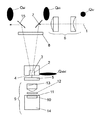
図1に図示した増幅器モジュールはレーザー光線、特にコリメートされたレーザー光線1を増幅するために使用する。レーザー光線1は図示していない発振器により生成され、本実施形態では円形の光線横断面Qkrをもっている。
【0021】
レーザークリスタル2として実施されたレーザー活性固体媒体は互いに対向する2つの光線通過面3,4を有し、そのうち一方の光線通過面はポンピングミラー5にすぐ隣接する位置に配置されている。ポンピングミラー5(光線通過面4の表面膜として構成してもよい)はポンピング波長に対し透過性があり、レーザー光線の波長に対しては高反射性がある。光学的に活性な光線通過面3は、標準断面ではポンピング波長に対してもレーザー波長に対しても非反射性があるようにコーティングされていてよい。必要とするポンピング波長は、有利にはたとえば0.5%のドーピングを施したNd:YVO4結晶として構成されたレーザークリスタル2に対しては、803nmと809nmの間にある。本実施形態に対しては、1×4×4mm3のサイズのクリスタルが適している。Nd:YVO4結晶以外では、希土類をドープした他のクリスタルを使用してもよい。
【0022】
入射したレーザー光線1は、まず第1の面(接平面Etan)において、円筒レンズガリレイ型望遠鏡6により、この望遠鏡6の倍率に応じて、半軸比が小さな楕円形の光線横断面Qelに拡大される(2倍ないし3倍の拡大)。或いはこれに代えて、アナモルフィックプリズム対を使用してもよい。なお、発振器がすでに楕円形のレーザー光線を提供する場合には、もちろんこのような入口側の光線成形部を設けなくてもよい。光路内で下流側に配置される最初の折畳みミラー7は、レーザー光線1を偏向させて円筒レンズ8を通過させる。円筒レンズ8は、コリメートされたレーザー光線1を第2の面(サジタル面Esag)でレーザークリスタル2に合焦させる。接平面Etanにおいて以前コリメートされた状態にあるレーザー光線1(図3)はレーザークリスタル2を透過し、その際ポンピング光線にモードを整合せしめられて、かなり楕円形のフォーカスQstelをもっている。円筒レンズ8は、レーザークリスタル2内に形成されるサーマルレンズTLから、自らの焦点距離fzylだけ離れて配置されているので、生じたビームウェストはその領域内にある(図2)。
【0023】
ポンピングミラー5で反射したレーザー光線1は、円筒レンズ2の2回目の通過後、サジタル面Esagでも再びコリメートされて、円筒レンズ8を最初に通過したときと同じ楕円形の横断面をもっている。
【0024】
ポンピング光線を生成させるため、ダイオードレーザーモジュール9が設けられている。ダイオードレーザーモジュール9は、図示していない密封ケース内に、高速軸用のコリメーション光学系11を備えた少なくとも1つのレーザーダイオードセル10と、偏光を生じさせるための、オプショナルなλ/2位相遅延プレート12と、レーザークリスタル2にポンピング光線をフォーカシングするための非球面体13とを含んでいる。図示していないが、レーザーダイオードセル10の光線クオリティを改善するため、低速軸のオプショナルなコリメーション部も設けられている。さらに、非球面体13の代わりに、球面のレンズまたはレンズ装置を使用してもよい。
【0025】
ケースはモジュール構成要素を埃、湿気、化学性の蒸気、静電放電、機械的な損傷から保護する。レーザーダイオードセル10は、適当な取り付け技術により、ヒートシンクとして用いられる銅体14に固定されている。
【0026】
このような手段により生成されたポンピング光線は、レーザー光線1と同様にかなり楕円形の形状であり、ほぼ縦方向にポンピングされるレーザークリスタル2内部での光線横断面は、たとえば1μmないし500μmのサジタル面内での膨張、およびたとえば0.5mmないし3mmの接平面内での膨張により特徴づけられる。このように楕円形に形成されたポンピング光線は、レーザークリスタル2内でサーマルレンズを生じさせ、サーマルレンズは、方向に応じて温度勾配が異なっているために、互いに垂直である前記面Esagと面Etanにおいて異なる強さのものが形成される。たとえば、サジタル面Esag内でのサーマルレンズの焦点距離は(サジタル面内にはレーザーダイオードセル10の高速軸も延在している)40mmないし20mmの範囲であり、接平面Etanでは1000mmないし4000mmの範囲である。接平面Etan内のサーマルレンズは、その焦点距離が長いため、増幅対象であるレーザー光線1に対し不具合な結像機能をほとんど持っていない。焦点距離が長くなるにつれて、このような作用を実質的に阻止することができる。
【0027】
しかし、接平面Etan内のサーマルレンズの残留作用が弱ければ、増幅器モジュール内に補助的に配置される結像要素、たとえば長焦点距離の、凸に湾曲した円筒レンズ、または球面レンズによってこの残留作用を補償することができ、或いは既存の構成要素を特別に構成することによって補償することもできる。このため、光路内において増幅器モジュールの出口に配置される第2の折畳みミラー15を利用することができる。折畳みミラー15により、レーザー光線1を反射により次の増幅段(他の増幅器モジュール)に提供することができる。この目的のため、図面に破線で示した折畳みミラー15は筒状に構成され、或いは球面凸状に構成され、必要な場合は適宜傾斜して配置される。球面鏡を使用する場合、サジタル面Esagでの光線の影響は、曲率半径が大きいためにわずかである。これは図5から明らかである。同様のことは長焦点距離の球面レンズに対しても当てはまる。というのは、サジタル面Esagでは、短焦点距離のレンズだけが結像を決定するからである。いずれにしろ、接平面Etan内でのモードの整合は、円筒レンズ望遠鏡6内でのレンズ間隔を設定することにより可能である。接平面Etan内でのサーマルレンズTLの残留作用の補正が必要でない場合は、或いは補正レンズによって行う場合は、第2の折畳みミラー15を平面鏡として構成してもよい。
【0028】
図4に図示した多段増幅器は、増幅段の数量に整合した数量の増幅器モジュールを有している。これらの増幅器モジュールの構成要素には図1の構成要素と同じ符号を付した。レーザークリスタル2に付設されているダイオードレーザーモジュール9は、増幅器のためのポンピング装置を形成している。個々のレーザーダイオードセル10は電気的に有利にはシリアルに接続され、同じダイオード温度で作動する。
【0029】
本実施形態では1個の増幅段ごとに設けられているレーザークリスタルに、複数個のレーザーダイオードセルを付設してもよい。他方、1個のレーザーダイオードセルにつき複数個のレーザークリスタルを備えた構成でもよい。結像要素のために設けられる位置調整手段16ないし22は、増幅器の位置調整状態を設定するために用いる。この位置調整状態は、焦点距離fzylによって決定される円筒レンズ8とサーマルレンズとの距離と同様に、サジタル面Esag内の強力なサーマルレンズの大きさに依存しないので、更なる整合、特にダイオード電流変化時の整合は必要ない。
【0030】
図1のモード整合は円筒レンズを用いて増幅器モジュールに対し入口側しか行われていないが、装置の対称性に基づき、出口にも円筒レンズ望遠鏡23の形態で適当なモード整合部を設けて、入口と出口で互いに対称な光線を生じさせてもよい。レーザークリスタル2はその破壊限界よりもかなり下の値で作動するが、適当な取り付け技術、たとえば蝋付け、インジウムプレス、または接着でヒートシンク24上に固定されている。
【0031】
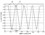
図4の多段増幅器は、図5ないし図8に図示したビーム特性を有している。図示していない発振器からの距離に依存して、サジタル面Esag内でのレーザー光線1のビーム径は主に円筒レンズ8の作用によって決定される(図5)。円筒レンズ8の作用が強ければ強いほど、システムの揺らぎは小さい。球面凸状に構成された折畳みミラー15の影響は、接平面Etan内の長いミラー焦点距離とサジタル面Esag内の円筒レンズ8の短い焦点距離との大きな焦点距離比により十分に補正されている。サジタル面Esag内の強力なサーマルレンズTLsagは、レーザークリスタル2内でのビーム伝播(図6)および増幅器の出口におけるビーム伝播(図7)に悪影響を及ぼさない。両ケースとも、強力なサーマルレンズTLsagの焦点距離の変化により、ビーム径の変動はわずかである。
【0032】
図8によれば、接平面Etan内で円筒レンズ望遠鏡6によって拡大したレーザー光線1は弱いサーマルレンズTLtanを透過し、その際球面凸状に構成された折畳みミラー15により修正が行なわれる。増幅器出口では、円筒レンズ望遠鏡23により対称化が行なわれる。なお接平面Etan内では、低速軸のポンピング光線のクオリティは著しく悪化している。
【図面の簡単な説明】
【図1】増幅器モジュールの構成図である。
【図2】増幅器モジュール内の光路をサジタル面で示した図である。
【図3】増幅器モジュール内の光路を接平面で示した図である。
【図4】4個の増幅器モジュールからなる4段増幅器を示す図である。
【図5】図4の増幅器におけるサジタル面内でのビーム径の変化を示すグラフである。
【図6】図4の増幅器のレーザークリスタル内でのビーム径とサジタル面内でのサーマルレンズの強さとの関係を示すグラフである。
【図7】図4の増幅器の増幅器出口におけるビーム径とサジタル面内でのサーマルレンズの強さとの関係を示すグラフである。
【図8】図4の増幅器の接平面内でのビーム径の変化を示すグラフである。
【符号の説明】
1 レーザー光線
2 レーザークリスタル
3,4 光線通過面
5 ポンピングミラー
6 円筒レンズガリレイ型望遠鏡
7 折畳みミラー
8 円筒レンズ
9 ダイオードレーザーモジュール
10 レーザーダイオードセル
11 コリメーション光学系
12 λ/2位相遅延プレート
13 非球面体
14 銅体
15 折畳みミラー
16ないし22 位置調整手段
23 円筒レンズ望遠鏡
24 ヒートシンク[0001]
BACKGROUND OF THE INVENTION
The present invention comprises at least one laser active solid medium, and when the laser beam to be amplified is transmitted through the laser active solid medium, the mode is matched with the pumping beam, and the elliptical pumping beam is incident on the laser beam. the incident direction and strength in parallel to each other in a plane perpendicular of the active solid medium in the pumping light is different from the thermal lens is formed, to a laser amplifier pumped by a diode.
[0002]
[Prior art]
As is well known, fundamental mode oscillators in the field of solid state lasers can only be configured below a certain output value due to the optothermal properties of the laser active medium used. For this reason, in order to produce a high output, the oscillator is often combined with a laser amplifier disposed downstream in the optical path. A laser amplifier can maintain a high quality beam of oscillator light.
[0003]
Also, this type of oscillator / amplifier device has the advantage that the oscillator can be operated with relatively low power. In this manner, in the case of the mode coupling short pulse laser, the saturable semiconductor absorber disposed inside the resonator can be protected from an excessive load.
[0004]
A known device of this kind, for example the device described in US Pat. No. 5,237,584, has the disadvantage of high positioning sensitivity. A multi-stage amplifier is supplied with an oscillator and an output beam with matching modes. The amplifier has a laser crystal that is pumped with a diode, and a folding mirror is arranged opposite the laser crystal. In order to compensate for the strong thermal lens formed in the laser crystal, it is necessary to match the radius of curvature of the folding mirror and the distance between the folding mirror and the laser crystal with high accuracy. If not matched, a stable optical system cannot be guaranteed. A serious drawback of this type of serial configuration is that the individual individual variability (Exemplarschwankung) must always be readjusted. Since the tolerance width is very small, the system will fail if there are slight fluctuations in the diode parameters due to, for example, fatigue, or individual fluctuations in the laser crystal.
[0005]
In the case of the laser system described in U.S. Pat. No. 5,696,786, the above drawbacks become more serious. This is because the laser system is not provided with an intermediate imaging element, so that the optical path cannot be aligned with the thermal lens. This type of laser device typically has only a small operation window for the diode current.
[0006]
Alternatively, a folding type optical path may be realized in the crystal instead of the above configuration (US Pat. No. 5,271,031). For this reason, the beam passes through different pumping regions of this crystal many times in succession. This apparatus also has the same drawbacks as the laser system described in the aforementioned US Pat. No. 5,696,786.
[0007]
Finally, according to DE 19521943, a relatively flat elliptical isothermal field is formed in the laser crystal for a solid-state laser device that is pumped in the longitudinal direction. It is known to use a gate-like convex lens or cylindrical lens to occur spontaneously and uncontrolled.
[0008]
[Problems to be solved by the invention]
The object of the present invention is to significantly increase the tolerances of the amplifying device with respect to variations in input parameters, thereby eliminating the need for fine matching to ensure the stability of the amplifier.
[0009]
[Means for Solving the Problems]
In order to solve the above-mentioned problems, the present invention comprises at least one laser active solid medium , the mode of which is matched to the pumping light beam when the laser beam to be amplified passes through the laser active solid medium, and the elliptical pumping light beam. by but the incident intensity in mutually perpendicular plane parallel to the incident direction of the pumping light in the laser-active solid medium is different thermal lens is formed, the laser amplifier pumped by diode, the beam of the laser beam Is directed into the laser active solid medium so as to be focused in the plane having the strong thermal lens, and the beam waist formed at that time is in the region of the strong thermal lens. Is.
[0011]
Since the distance between the cylindrical lens and the laser active medium to be set is not a function of the thermal lens, it is sufficient to set the nominal distance of the focal length once. Individual thermal lenses, such as those found in amplifiers with multiple amplification stages, do not need to be considered to form a stable system. It became clear that the thermal lens in the region of the beam waist does not affect the beam propagation. Unlike conventional solutions where the influence of the thermal lens effect on the beam path must be compensated by a highly sensitive position adjustment operation, in the present invention, the action of the thermal lens is already substantially eliminated by the amplifier configuration. Mode matching between the laser beam and the pumping beam is performed in a plurality of mutually independent planes of the thermal lens having different strengths (refractive powers) of the thermal lens. As a result, the amplification factor, beam quality, and beam parameters of the amplifier are not affected by the diode parameters, so that the pumping diode configured as a laser diode cell can be operated electrically serially and at the same temperature. Also, different thermal lenses resulting from different individual diode laser characteristics and spectral characteristics, unlike prior art solutions, lose their action and do not need to be compensated for by tedious alignment procedures.
[0012]
According to the present invention, an amplifier can be configured in a compact and low-cost manner, and the number of amplification stages that are strictly modular is scalable. That is, the output of each amplification stage forms the input of the next amplification stage except for the final stage. According to the present invention, there is provided an amplifying apparatus capable of producing a large manufacturing tolerance in manufacturing a simple standard component that is required despite a small individual variation of the amplifier.
[0013]
According to the apparatus according to the present invention, rays of the oscillator while maintaining the beam quality to be determined by the by diffraction measurement factor M 2 defined by an oscillator, the low-power, is amplified by the mode of operation is particularly mode-locking Can do. The serial amplifier could be constructed with high stability and reproducibility. Furthermore, the present invention eliminates the need for expensive and reduced efficiency beam shaping optics for the pumping diode. Using beam optics, a rearrangement is performed to symmetrize the beam parameter product about the fast and slow axes of the diode.
[0014]
Using at least one laser diode cell as the pumping light source, diodes in the elliptical pumping focus to produce means for collimating the fast axis and thermal lenses formed with different intensities in planes perpendicular to each other Advantageously, means are provided for focusing the light beam.
[0015]
In order to set or adjust the polarization of the pumping light beam, a λ / 2 phase retardation plate may be attached to the pumping light source .
[0016]
The pumping light beam passes through the beam passing surface of the laser active solid medium on the pumping light source side, and the laser light beam passes through the beam passing surface on the laser light source side of the laser active solid medium facing the beam passing surface. , Each directed into a laser active solid medium. Since the beam passing surface on the pumping beam source side is configured to be highly reflective to the wavelength of the laser beam, the laser beam newly passes through the laser active solid medium and the focusing element after reflection.
[0017]
The optical element provided at the entrance of the amplifier to expand the laser beam in a plane with a weak thermal lens may be configured as a cylindrical lens Galilei telescope or as a pair of anamorphic prisms.
[0018]
Advantageously, at least one imaging element is provided in the optical path of the laser beam to compensate at the amplifier exit for weak thermal lenses in one plane. This imaging element can be a cylindrical mirror configured as a folding mirror, or a spherical mirror, or a convex cylindrical lens with a long focal length in the optical path of the laser beam emitted from the laser active solid medium or A spherical lens having a long focal length may be arranged.
[0019]
As the laser active solid medium, Nd : YVO 4 crystal with 0.5% doping may be used. The Nd : YVO 4 crystal is pumped at a wavelength in the range of 803 nm to 809 nm.
[0020]
DETAILED DESCRIPTION OF THE INVENTION
The amplifier module shown in FIG. 1 is used to amplify a laser beam, in particular a collimated laser beam 1. The laser beam 1 is generated by an oscillator (not shown), and has a circular beam cross section Q kr in this embodiment.
[0021]
The laser active solid medium implemented as a
[0022]
The incident laser beam 1 is first formed on the first surface (tangent plane E tan ) by the cylindrical lens
[0023]
The laser beam 1 reflected by the
[0024]
A
[0025]
The case protects the module components from dust, moisture, chemical vapors, electrostatic discharge, and mechanical damage. The
[0026]
The pumping beam generated by such means has a substantially elliptical shape like the laser beam 1, and the beam cross section inside the
[0027]
However, if the residual action of the thermal lens in the tangential plane E tan is weak, this residual effect is caused by an imaging element, for example a long focal length convexly curved cylindrical lens or a spherical lens, which is arranged in the amplifier module. The effect can be compensated, or it can be compensated by specially configuring existing components. For this reason, the
[0028]
The multistage amplifier shown in FIG. 4 has a number of amplifier modules matched to the number of amplification stages. The components of these amplifier modules are denoted by the same reference numerals as those of FIG. The
[0029]
In the present embodiment, a plurality of laser diode cells may be attached to a laser crystal provided for each amplification stage. On the other hand, the structure provided with several laser crystals per laser diode cell may be sufficient. Position adjusting means 16 to 22 provided for the imaging element are used for setting the position adjustment state of the amplifier. Since this position adjustment state does not depend on the size of the strong thermal lens in the sagittal plane E sag , as well as the distance between the
[0030]
The mode matching of FIG. 1 is performed only on the entrance side with respect to the amplifier module using a cylindrical lens. However, based on the symmetry of the apparatus, an appropriate mode matching portion is provided at the exit in the form of the
[0031]
The multistage amplifier shown in FIG. 4 has the beam characteristics shown in FIGS. Depending on the distance from the oscillator (not shown), the beam diameter of the laser beam 1 within the sagittal plane E sag is mainly determined by the action of the cylindrical lens 8 (FIG. 5). The stronger the action of the
[0032]
According to FIG. 8, the laser beam 1 magnified by the
[Brief description of the drawings]
FIG. 1 is a configuration diagram of an amplifier module.
FIG. 2 is a diagram showing an optical path in an amplifier module in a sagittal plane.
FIG. 3 is a diagram showing an optical path in an amplifier module in a tangential plane.
FIG. 4 is a diagram showing a four-stage amplifier including four amplifier modules.
5 is a graph showing a change in beam diameter in the sagittal plane in the amplifier of FIG. 4;
6 is a graph showing the relationship between the beam diameter in the laser crystal of the amplifier of FIG. 4 and the strength of the thermal lens in the sagittal plane.
7 is a graph showing the relationship between the beam diameter at the amplifier outlet of the amplifier of FIG. 4 and the strength of the thermal lens in the sagittal plane.
8 is a graph showing a change in beam diameter in the tangent plane of the amplifier of FIG. 4;
[Explanation of symbols]
DESCRIPTION OF SYMBOLS 1
Claims (14)
増幅対象であるレーザー光線がレーザー活性固体媒体を透過する際にポンピング光線にモードを整合せしめられ、
楕円形状のポンピング光線が入射することにより、レーザー活性固体媒体内にポンピング光線の入射方向と平行で互いに垂直な面内において強さが異なるサーマルレンズが形成される、
ダイオードでポンピングされるレーザー増幅器において、
前記レーザー光線のビーム(1)が、強いサーマルレンズ(TL)をもった面内において合焦するようにレーザー活性固体媒体の中へ指向しており、その際に形成されるビームウェストが前記強いサーマルレンズの領域にあることを特徴とするレーザー増幅器。Comprising at least one laser active solid medium;
When the laser beam to be amplified passes through the laser active solid medium, the mode is matched to the pumping beam ,
By pumping light of elliptical incident, strength in mutually perpendicular plane parallel to the incident direction of the pumping light in the laser-active solid medium is different thermal lens is formed,
In a diode-pumped laser amplifier,
Said laser beam (1) is a strong in a thermal lens has been in the plane (TL) is directed into the laser-active solid medium to focus, a strong beam waist formed at that time the thermal laser amplifier, characterized in that in the region of lens.
Applications Claiming Priority (2)
| Application Number | Priority Date | Filing Date | Title |
|---|---|---|---|
| DE10043269A DE10043269C2 (en) | 2000-08-29 | 2000-08-29 | Diode pumped laser amplifier |
| DE10043269:7 | 2000-08-29 |
Publications (3)
| Publication Number | Publication Date |
|---|---|
| JP2002141589A JP2002141589A (en) | 2002-05-17 |
| JP2002141589A5 JP2002141589A5 (en) | 2009-03-26 |
| JP4374162B2 true JP4374162B2 (en) | 2009-12-02 |
Family
ID=7654745
Family Applications (1)
| Application Number | Title | Priority Date | Filing Date |
|---|---|---|---|
| JP2001259734A Expired - Fee Related JP4374162B2 (en) | 2000-08-29 | 2001-08-29 | Diode-pumped laser amplifier |
Country Status (6)
| Country | Link |
|---|---|
| US (1) | US6661568B2 (en) |
| JP (1) | JP4374162B2 (en) |
| CA (1) | CA2354632C (en) |
| DE (1) | DE10043269C2 (en) |
| FR (1) | FR2813451B1 (en) |
| GB (1) | GB2370684B (en) |
Families Citing this family (40)
| Publication number | Priority date | Publication date | Assignee | Title |
|---|---|---|---|---|
| DE10232124A1 (en) * | 2002-07-12 | 2004-02-12 | Jenoptik Laser, Optik, Systeme Gmbh | Pulse laser arrangement and method for pulse length adjustment for laser pulses |
| DE10240599A1 (en) * | 2002-08-30 | 2004-03-18 | Jenoptik Laser, Optik, Systeme Gmbh | Arrangement and method for generating ultra-short laser pulses |
| US6898231B2 (en) * | 2002-11-21 | 2005-05-24 | Coherent, Inc. | Off-peak optical pumping of yttrium orthovanadate |
| US8921733B2 (en) | 2003-08-11 | 2014-12-30 | Raydiance, Inc. | Methods and systems for trimming circuits |
| US9022037B2 (en) | 2003-08-11 | 2015-05-05 | Raydiance, Inc. | Laser ablation method and apparatus having a feedback loop and control unit |
| WO2005018061A2 (en) * | 2003-08-11 | 2005-02-24 | Raydiance, Inc. | Pumping of optically-pumped amplifiers |
| US7535633B2 (en) * | 2005-01-10 | 2009-05-19 | Kresimir Franjic | Laser amplifiers with high gain and small thermal aberrations |
| US7386019B2 (en) | 2005-05-23 | 2008-06-10 | Time-Bandwidth Products Ag | Light pulse generating apparatus and method |
| US9066194B2 (en) | 2005-07-14 | 2015-06-23 | Binj Laboratories, Inc. | System and method for detecting and controlling transmission devices |
| CN100555016C (en) * | 2005-09-09 | 2009-10-28 | 鸿富锦精密工业(深圳)有限公司 | Digital camera lens and use the numerical camera mould of this camera lens |
| US20070098024A1 (en) * | 2005-10-28 | 2007-05-03 | Laserscope | High power, end pumped laser with off-peak pumping |
| US9130344B2 (en) | 2006-01-23 | 2015-09-08 | Raydiance, Inc. | Automated laser tuning |
| US8232687B2 (en) | 2006-04-26 | 2012-07-31 | Raydiance, Inc. | Intelligent laser interlock system |
| US7408971B2 (en) * | 2006-02-28 | 2008-08-05 | Quantronix Corporation | Longitudinally pumped solid state laser and methods of making and using |
| KR100815483B1 (en) * | 2007-05-09 | 2008-03-20 | 한국전기연구원 | Diode pumped laser apparatus using anisotropic laser crystal |
| US7573930B2 (en) * | 2007-06-14 | 2009-08-11 | Innovavent Gmbh | Anamorphotic solid-sate laser |
| US7903326B2 (en) | 2007-11-30 | 2011-03-08 | Radiance, Inc. | Static phase mask for high-order spectral phase control in a hybrid chirped pulse amplifier system |
| US7773655B2 (en) * | 2008-06-26 | 2010-08-10 | Vadim Chuyanov | High brightness laser diode module |
| AU2009289425B2 (en) | 2008-09-05 | 2013-10-24 | Ams Research Corporation | Laser system having switchable power modes |
| US8897326B2 (en) * | 2008-09-08 | 2014-11-25 | Ams Research Corporation | Pump energy wavelength stabilization |
| US8498538B2 (en) | 2008-11-14 | 2013-07-30 | Raydiance, Inc. | Compact monolithic dispersion compensator |
| JP2011099631A (en) * | 2009-11-06 | 2011-05-19 | Denso Corp | Heat exchanger |
| DE102010009048A1 (en) * | 2010-02-23 | 2011-08-25 | LPKF Laser & Electronics AG, 30827 | laser assembly |
| JP2011199181A (en) * | 2010-03-23 | 2011-10-06 | Kataoka Seisakusho:Kk | Laser amplifier |
| WO2012021748A1 (en) | 2010-08-12 | 2012-02-16 | Raydiance, Inc. | Polymer tubing laser micromachining |
| KR20140018183A (en) | 2010-09-16 | 2014-02-12 | 레이디안스, 아이엔씨. | Laser based processing of layered materials |
| US8554037B2 (en) | 2010-09-30 | 2013-10-08 | Raydiance, Inc. | Hybrid waveguide device in powerful laser systems |
| EP2564972B1 (en) * | 2011-09-05 | 2015-08-26 | ALLTEC Angewandte Laserlicht Technologie Gesellschaft mit beschränkter Haftung | Marking apparatus with a plurality of lasers, deflection means and telescopic means for each laser beam |
| ES2530070T3 (en) * | 2011-09-05 | 2015-02-26 | ALLTEC Angewandte Laserlicht Technologie Gesellschaft mit beschränkter Haftung | Marking apparatus with a plurality of individually adjustable lasers and sets of deflection means |
| EP2565994B1 (en) | 2011-09-05 | 2014-02-12 | ALLTEC Angewandte Laserlicht Technologie Gesellschaft mit beschränkter Haftung | Laser device and method for marking an object |
| EP2564976B1 (en) | 2011-09-05 | 2015-06-10 | ALLTEC Angewandte Laserlicht Technologie Gesellschaft mit beschränkter Haftung | Marking apparatus with at least one gas laser and heat dissipator |
| ES2438751T3 (en) | 2011-09-05 | 2014-01-20 | ALLTEC Angewandte Laserlicht Technologie Gesellschaft mit beschränkter Haftung | Device and procedure for marking an object by means of a laser beam |
| EP2564974B1 (en) * | 2011-09-05 | 2015-06-17 | ALLTEC Angewandte Laserlicht Technologie Gesellschaft mit beschränkter Haftung | Marking apparatus with a plurality of gas lasers with resonator tubes and individually adjustable deflection means |
| DK2564973T3 (en) * | 2011-09-05 | 2015-01-12 | Alltec Angewandte Laserlicht Technologie Ges Mit Beschränkter Haftung | Marking apparatus having a plurality of lasers and a kombineringsafbøjningsindretning |
| DK2565996T3 (en) | 2011-09-05 | 2014-01-13 | Alltec Angewandte Laserlicht Technologie Gmbh | Laser device with a laser unit and a fluid container for a cooling device of the laser unit |
| US10239160B2 (en) | 2011-09-21 | 2019-03-26 | Coherent, Inc. | Systems and processes that singulate materials |
| WO2014050720A1 (en) | 2012-09-27 | 2014-04-03 | 株式会社 村田製作所 | Piezoelectric actuator, method for manufacturing same, and magnetic disc apparatus |
| US9769913B2 (en) | 2013-02-01 | 2017-09-19 | Inter-University Research Institute Corporation High Energy Accelerator Research Organization | Burst-laser generator using an optical resonator |
| EP3896804B1 (en) * | 2019-01-08 | 2023-03-15 | Mitsubishi Electric Corporation | Laser amplifier |
| US11796817B2 (en) | 2022-01-21 | 2023-10-24 | Lightspace Group, Inc. | Optical arrangement for expanding and uniformizing light beams |
Family Cites Families (17)
| Publication number | Priority date | Publication date | Assignee | Title |
|---|---|---|---|---|
| US5271031A (en) * | 1985-05-01 | 1993-12-14 | Spectra Physics Laser Diode Systems | High efficiency mode-matched solid-state laser with transverse pumping and cascaded amplifier stages |
| US5103457A (en) * | 1990-02-07 | 1992-04-07 | Lightwave Electronics Corporation | Elliptical mode cavities for solid-state lasers pumped by laser diodes |
| US5046070A (en) * | 1990-05-22 | 1991-09-03 | Coherent, Inc. | Longitudinally laser pumped laser with compensation for thermal lens effects |
| US5237584A (en) * | 1991-11-08 | 1993-08-17 | Lightwave Electronics Corporation | High power optical cavity for end-pumped solid state laser |
| US5696786A (en) * | 1993-04-15 | 1997-12-09 | The United States Of America As Represented By The Secretary Of The Air Force | Solid-state laser system |
| US5528612A (en) * | 1993-11-19 | 1996-06-18 | The United States Of America As Represented By The Secretary Of The Navy | Laser with multiple gain elements |
| US5561547A (en) * | 1994-02-04 | 1996-10-01 | Spectra-Physics Lasers, Inc. | Thermal lens of controlled ellipicity |
| US5461637A (en) * | 1994-03-16 | 1995-10-24 | Micracor, Inc. | High brightness, vertical cavity semiconductor lasers |
| US5530711A (en) * | 1994-09-01 | 1996-06-25 | The United States Of America As Represented By The Secretary Of The Navy | Low threshold diode-pumped tunable dye laser |
| GB9511688D0 (en) * | 1995-06-09 | 1995-08-02 | Lumonics Ltd | Laser system |
| US5757842A (en) * | 1996-06-28 | 1998-05-26 | International Business Machines Corporation | Method and apparatus for compensating thermal lensing effects in a laser cavity |
| US5875160A (en) * | 1996-12-14 | 1999-02-23 | Ricoh Company, Ltd. | Method and device for initializing optical recording medium of phase change type, and optical recording medium |
| US5912912A (en) * | 1997-09-05 | 1999-06-15 | Coherent, Inc. | Repetitively-pulsed solid-state laser having resonator including multiple different gain-media |
| US6022114A (en) * | 1998-05-01 | 2000-02-08 | Nikon Corporation | Anamorphic afocal beam shaping assembly |
| US6141143A (en) * | 1998-05-01 | 2000-10-31 | Light Solutions Corporation | CW laser amplifier |
| DE19845786A1 (en) * | 1998-09-21 | 2000-05-25 | Bernd Ozygus | Optical arrangement to improve focusing ability of laser diode beams; has several plates that displace parts of laser beam to improve focusing ability in one of two spatial directions |
| US6417955B1 (en) * | 1999-12-14 | 2002-07-09 | Spectra Physics Lasers, Inc. | Stack pumped vanadate amplifier |
-
2000
- 2000-08-29 DE DE10043269A patent/DE10043269C2/en not_active Expired - Fee Related
-
2001
- 2001-08-02 CA CA002354632A patent/CA2354632C/en not_active Expired - Fee Related
- 2001-08-07 FR FR0110534A patent/FR2813451B1/en not_active Expired - Fee Related
- 2001-08-24 US US09/939,401 patent/US6661568B2/en not_active Expired - Lifetime
- 2001-08-29 JP JP2001259734A patent/JP4374162B2/en not_active Expired - Fee Related
- 2001-08-29 GB GB0120928A patent/GB2370684B/en not_active Expired - Fee Related
Also Published As
| Publication number | Publication date |
|---|---|
| GB2370684A (en) | 2002-07-03 |
| CA2354632A1 (en) | 2002-02-28 |
| DE10043269A1 (en) | 2002-04-04 |
| FR2813451B1 (en) | 2006-02-03 |
| FR2813451A1 (en) | 2002-03-01 |
| US6661568B2 (en) | 2003-12-09 |
| US20020036821A1 (en) | 2002-03-28 |
| CA2354632C (en) | 2008-05-20 |
| JP2002141589A (en) | 2002-05-17 |
| DE10043269C2 (en) | 2002-10-24 |
| GB2370684B (en) | 2002-12-18 |
| GB0120928D0 (en) | 2001-10-17 |
Similar Documents
| Publication | Publication Date | Title |
|---|---|---|
| JP4374162B2 (en) | Diode-pumped laser amplifier | |
| US5271031A (en) | High efficiency mode-matched solid-state laser with transverse pumping and cascaded amplifier stages | |
| JP3265173B2 (en) | Solid state laser device | |
| US4837771A (en) | High-efficiency mode-matched solid-state laser with transverse pumping and cascaded amplifier stages | |
| US20020085608A1 (en) | High power and high gain saturation diode pumped laser means and diode array pumping device | |
| JP2004258624A (en) | Laser beam synthesizer | |
| US5359622A (en) | Radial polarization laser resonator | |
| US11201450B2 (en) | Q-switched solid-state laser | |
| JPH11514797A (en) | Laser amplifier | |
| JPS6182488A (en) | Solid state laser device | |
| EP1186078B1 (en) | Diode laser-pumped solid state laser | |
| JP3621623B2 (en) | Laser resonator | |
| US8611393B2 (en) | Laser apparatus | |
| JP3211770B2 (en) | Solid-state laser device and solid-state laser amplifier having the same | |
| US7003011B2 (en) | Thin disk laser with large numerical aperture pumping | |
| US4255718A (en) | Transversely pumped dye laser having improved conversion efficiency | |
| US11387620B2 (en) | Compact Raman laser capable of efficient operation at low peak powers with good beam quality | |
| JP2006203117A (en) | Solid-state laser device | |
| CN114552347B (en) | Thermally tuned hollow laser and zooming system | |
| US20230271273A1 (en) | Laser apparatus and laser machining apparatus | |
| US20030202554A1 (en) | Laser resonator | |
| JPH0637368A (en) | Laser and beam expander | |
| JP2000286488A (en) | Laser system | |
| JP2023553749A (en) | laser beam amplification device | |
| JP2009004818A (en) | Solid-state laser beam oscillator and solid-state laser beam oscillation device |
Legal Events
| Date | Code | Title | Description |
|---|---|---|---|
| A621 | Written request for application examination |
Free format text: JAPANESE INTERMEDIATE CODE: A621 Effective date: 20080826 |
|
| A521 | Written amendment |
Free format text: JAPANESE INTERMEDIATE CODE: A523 Effective date: 20090209 |
|
| A871 | Explanation of circumstances concerning accelerated examination |
Free format text: JAPANESE INTERMEDIATE CODE: A871 Effective date: 20090209 |
|
| A975 | Report on accelerated examination |
Free format text: JAPANESE INTERMEDIATE CODE: A971005 Effective date: 20090217 |
|
| A131 | Notification of reasons for refusal |
Free format text: JAPANESE INTERMEDIATE CODE: A131 Effective date: 20090224 |
|
| A521 | Written amendment |
Free format text: JAPANESE INTERMEDIATE CODE: A523 Effective date: 20090521 |
|
| A131 | Notification of reasons for refusal |
Free format text: JAPANESE INTERMEDIATE CODE: A131 Effective date: 20090707 |
|
| A521 | Written amendment |
Free format text: JAPANESE INTERMEDIATE CODE: A523 Effective date: 20090709 |
|
| TRDD | Decision of grant or rejection written | ||
| A01 | Written decision to grant a patent or to grant a registration (utility model) |
Free format text: JAPANESE INTERMEDIATE CODE: A01 Effective date: 20090811 |
|
| A01 | Written decision to grant a patent or to grant a registration (utility model) |
Free format text: JAPANESE INTERMEDIATE CODE: A01 |
|
| A61 | First payment of annual fees (during grant procedure) |
Free format text: JAPANESE INTERMEDIATE CODE: A61 Effective date: 20090907 |
|
| FPAY | Renewal fee payment (event date is renewal date of database) |
Free format text: PAYMENT UNTIL: 20120911 Year of fee payment: 3 |
|
| R150 | Certificate of patent or registration of utility model |
Free format text: JAPANESE INTERMEDIATE CODE: R150 |
|
| FPAY | Renewal fee payment (event date is renewal date of database) |
Free format text: PAYMENT UNTIL: 20120911 Year of fee payment: 3 |
|
| FPAY | Renewal fee payment (event date is renewal date of database) |
Free format text: PAYMENT UNTIL: 20130911 Year of fee payment: 4 |
|
| R250 | Receipt of annual fees |
Free format text: JAPANESE INTERMEDIATE CODE: R250 |
|
| LAPS | Cancellation because of no payment of annual fees |