JP4374146B2 - Spark plug evaluation method and manufacturing method - Google Patents
Spark plug evaluation method and manufacturing method Download PDFInfo
- Publication number
- JP4374146B2 JP4374146B2 JP2001055779A JP2001055779A JP4374146B2 JP 4374146 B2 JP4374146 B2 JP 4374146B2 JP 2001055779 A JP2001055779 A JP 2001055779A JP 2001055779 A JP2001055779 A JP 2001055779A JP 4374146 B2 JP4374146 B2 JP 4374146B2
- Authority
- JP
- Japan
- Prior art keywords
- tip
- electrode
- line
- discharge
- spark plug
- Prior art date
- Legal status (The legal status is an assumption and is not a legal conclusion. Google has not performed a legal analysis and makes no representation as to the accuracy of the status listed.)
- Expired - Lifetime
Links
Images


Description
【0001】
【発明の属する技術分野】
本発明はスパークプラグの評価方法及び製造方法に関し、更に詳しくは、長寿命であると共に、横飛び火現象や放電電圧のバラツキを防止して着火性を向上させ、未燃焼ガスの排出を抑制することができるスパークプラグの評価方法及び製造方法に関する。
【0002】
【従来の技術】
スパークプラグを長期間使用すると、火花による焼損により、中心電極及び外側電極が消耗し、両電極間で形成される放電ギャップが拡大する。これにより、ギャップで火花放電を行なうのに必要な要求電圧が上昇して、点火システムが持つ電源の最大能力を超えたり、あるいは、正規のギャップでなく、外側電極の端面や主体金具端面へ火花が逃げてしまうことがある。その結果、燃焼ガスへの確実な着火ができなくなり、スパークプラグ自体の耐久性の低下につながる。
【0003】
そのため、従来のスパークプラグにおいては、耐火花消耗性材料としてPt又はPt合金からなる中軸チップを中心電極の先端に接合して、放電ギャップの拡大の抑制を図っている。ところで、Ptは融点が約1800℃程度であり、このようなPt又はPt合金からなる中軸チップが設けられたスパークプラグを長期間使用すると、チップ表面が部分的に溶融して該チップ上に発汗粒が生じ成長していく。そして、かかる発汗粒がチップ上に生じることにより、放電ギャップの拡大が抑制され、放電電圧を低減させると共に横飛び火現象を抑えるという効果がある。しかし、融点がやや低いことから、火花が飛んでチップが焼損することにより、電極消耗の抑制効果がある程度限定されてしまうという問題点がある。
【0004】
そこで、かかるPt又はPt合金からなる中軸チップを使用した場合よりもさらに電極消耗の抑制効果を図るべく、中軸チップとして、Ir又はIr合金からなる中軸チップを使用したスパークプラグが開発されている(特開平9−219274号公報等)。Irは融点が約2400℃とPtに比べると高いので、Ptと比較して、チップの耐久性を向上させて、火花による焼損を抑えることができる結果、スパークプラグの寿命延長を図ることができる。
【0005】
【発明が解決しようとする課題】
しかし、Irの融点はPtよりも高いことから、チップの耐久性が向上して火花による焼損を抑えることができる反面、チップ上に発汗粒が形成されにくくなる。例えば、このようなIrチップを使用したスパークプラグにおいて、外側電極との間にきれいに芯が出ていれば特に問題はないが、製造上、ある程度ずれが生じることもある。そして、このようなずれがある場合、Ptでは発汗粒が形成されるので、放電ギャップの拡大が抑制され、放電電圧が安定してうまく火花が飛ぶが、Irでは発汗粒が生じないため、放電電圧が上昇しやすくなり、主体金具端面等へ横飛びする頻度が高くなることがある。その結果、燃焼ガスの着火が妨げられ、未燃焼ガスが排出されてしまい、エンジンの効率が低下すると共に、排気ガスにより環境に影響を与えるおそれがある。
【0006】
本発明は、上記実情に鑑みてなされたものであり、長寿命であると共に、横飛び火現象や放電電圧のバラツキを防止して着火性を向上させ、未燃焼ガスの排出を抑制することができるスパークプラグの評価方法及び製造方法を提供することを目的とする。
【0007】
【課題を解決するための手段】
本発明者は上記実情に鑑みて検討した結果、中心電極の先端にIrを主体とする中軸チップを設け、且つ、放電ギャップを含め、外側電極の端面と中軸チップとの位置関係を所定の範囲とすることにより、スパークプラグの寿命延長を可能にすると共に、横飛び火現象や放電電圧のバラツキを防止することができることを見出して本発明を完成するに至った。
【0008】
本発明のスパークプラグの評価方法は、中心貫通孔を有する絶縁体と、上記中心貫通孔に保持される中心電極と、上記絶縁体の径方向周囲に配置され、内燃機関取付用のネジを有する主体金具と、該主体金具に一端が接合部によって接合され、他端側が上記中心電極に放電ギャップを隔てて対向する放電面を有する外側電極と、を備えるスパークプラグの評価方法において、上記中心電極の上記放電ギャップを形成する先端は、先端面に向うに従って径小となる円錐台部を有し、上記中心電極の上記円錐台面の先端には、Irを主体とし、直径が0.3〜1.0mmの中軸チップが設けられ、上記中軸チップは、上記中心電極の上記円錐台面の先端に載置され、レーザー溶接によってストレート部を0.2mm以上残した形態で接合されており、上記外側電極の放電面には、自身の一部が上記中軸チップと同軸上になるとともに、上記接合面の外線部に形成された溶融合金部よりも上記中軸チップ側に自身の端面が突出されて外側チップが接合されており、上記内燃機関取付用のネジを基準にした仮想軸線との平行線を、上記放電ギャップに対して上記接合部と反対側から接近させてきた場合に、上記中軸チップの先端面を延長した平面と上記中軸チップの側面の延長面とによって形成される第一交線に最初に交わった位置における第一仮想線と、上記放電面を延長した平面と上記外側電極の先端面を延長した平面とによって形成される第二交線と、の間の距離(A)と、上記放電ギャップ(G)とが、G≦2A+0.5の関係を満たし、上記放電ギャップ(G)が0.85〜1.5mmであり、上記第二交線と、該第二交線を上記放電面に沿って該外側チップに接近させてきた場合に、上記外側チップと最初に交わった位置における第二仮想線と、の間の距離(B)が0.2mm以上であり、上記仮想軸線を上記放電ギャップに対して上記外側電極の接合部と反対側から近づけてきた場合に、上記中軸チップの先端面を延長した平面と上記第一交線とが最後に交わる位置における第三仮想線と、上記第二仮想線と、の間の距離(H)が0.3mm以上であればよいとするスパークプラグの評価方法である。また、本発明のスパークプラグの製造方法は、本発明の評価方法を含む。
【0009】
本発明のスパークプラグにおいて、上記「放電ギャップ」とは、図2のような場合は、上記中軸チップの先端面と外側電極(後述のように外側チップを設ける場合は外側チップ)の放電面との最短距離を示し、図5に示すように、中心電極がテーパー部を有する場合にも、中軸チップの先端面と外側電極又は外側チップの放電面の最短距離を示す。また、上記放電ギャップ(G)の値については特に限定はないが、通常0.7〜1.5mm、好ましくは0.7〜1.3mm、更に好ましくは0.85〜1.1mmである。かかる範囲とすることにより、放電ギャップ間に燃料によるブリッジが生じ難く、また、着火性の低下や過度の電極消耗を招くことがないことから好ましい。
【0010】
本発明のスパークプラグにおいて、上記「第一交線」とは、上記中軸チップの先端面を延長した平面と上記中軸チップの側面の延長面とによって形成されるものである。上記第一交線の部分は、中軸チップを切断した際のバリがでている場合があるが、この場合は、このバリの部分を切り取って第一交線を考えるものとする。尚、第一交線を構成することになる中軸チップの側面の延長面は、中軸チップの中心電極の中心軸線方向に切断した場合、例えば、中軸チップの両側面が略平行である場合には円柱面として表すことができる。
【0011】
本発明のスパークプラグにおける上記「第二交線」は、上記外側電極の放電面を延長した平面と、上記外側電極の先端面を延長した平面とによって形成される(図2参照)。外側電極の先端面は、コイル状の平角線を切断して外側電極を形成する際の切断面にあたることから、この先端面には段差が生じている場合がある。このような場合には、放電面に近い側の先端面を基準に第二交線を考えるものとする。そして、本発明のスパークプラグにおいて、上記距離(A)は、投影機を使用することで測定することができる。
【0012】
本発明のスパークプラグでは、上記放電ギャップ(G)と、上記距離(A)とがG≦2A+0.5の関係を満たすことにより、中心電極の放電ギャップを形成する先端にIr又はIr合金からなる中軸チップが使用される場合の利点である、火花放電に伴う電極の消耗を抑制することができる。その結果、スパークプラグの寿命延長を可能にすると共に、Ir又はIr合金を中軸チップとして使用した場合に懸念される横飛び現象や放電電圧のバラツキを防止するといった効果を奏する。尚、本発明において中軸チップが「Irを主体とする」とは、中軸チップにおいて、Irが最も重量含有率の高い成分であることを意味するものであり、必ずしも、50質量%以上を占める成分を意味するものではない。
【0013】
本発明のスパークプラグにおいて、上記外側電極の放電面には、外側電極の電極消耗を抑制するために、外側チップを設けて放電ギャップを形成してもよい。このように外側チップが設置される場合には、上記第二交線と、該第二交線を上記放電面に沿って該外側チップに接近させてきた場合に、上記外側チップと最初に交わった位置における第二仮想線と、の間の距離(B)を0.2mm以上、好ましくは0.3mm以上、更に好ましくは0.35〜0.8mmとする(図2参照)。この距離(B)が0.2mm未満では、外側チップが熱により外側電極から剥がれるおそれがあるので好ましくない。尚、上記外側チップを上記放電面に溶接により形成する場合は、その接合面外縁部に外側チップ成分と外側電極母材成分からなる溶融合金部が形成されることがある。このような場合には、この溶融合金部は考慮せずに、外側チップ自身と第二交線とが最初に交わった位置を第二仮想線とする。
【0014】
また、上記外側チップは、その一部が上記中軸チップと同軸上になるように設けられて、放電ギャップを形成することにより、火花放電による外側電極の放電面における異常消耗を抑制し、スパークプラグの寿命延長を可能とする。尚、外側チップは、中軸チップと同様にIrを主体に構成されていてもよく、その他にPt合金(例えば、Pt−NiやPt−Ir)により構成されていてもよい。
【0015】
本発明のスパークプラグにおいて、上記中軸チップは、上述のように、Ir又はIr合金から構成される。上記Ir合金としてはIrを最も重量含有率の高い成分として含んでいる限り特に限定はないが、Ir−Pt、Ir−Rh又はIr−Y2O3から構成されるチップとすると、より厳しい温度下でのチップの酸化揮発が抑制され、電極の消耗を抑制する上で好ましい。また、これらIr合金からなる中軸チップとしては、状態図における固相点として1900℃以上を持つものが、電極の消耗をより抑制する上で好ましい。
【0016】
上記中軸チップの直径は0.3〜1.0mm、好ましくは0.4〜0.8mmである。この直径が0.3mm未満では、高融点材質であるIr(Ir合金)を用いてチップを形成しても、チップとしての体積、放電ギャップを形成する面が小さく、火花放電による電極の消耗の抑制効果が小さくなるので好ましくない。一方、1.0mmを超えると、特殊な用途にスパークプラグが使用されない限りは、チップとしての放電ギャップを形成する面が大きく、その面により放電ギャップで発生した火花の熱を奪われてしまう(いわゆる消炎作用)ため、失火してしまうことが懸念され、着火性が悪化するため好ましくない。
【0017】
【発明の実施の形態】
以下、本発明について、試験例を挙げて具体的に説明する。
(1)本試験例のスパークプラグの構成
本試験例のスパークプラグPは、図1及び図2に示すように、筒状の主体金具1と、該主体金具1に挿設され、中心貫通孔21を有する絶縁体2と、上記絶縁体2の上記中心貫通孔21に挿設される中心電極3と、上記主体金具1に一端が接合部44によって接合された外側電極4と、を備える。
【0018】
上記主体金具1は低炭素鋼で形成され、その先端外周には内燃機関取付用のネジ(ネジの呼び:M14S、ネジリーチ:19mm)11と、スパークレンチと嵌合する六角形部(図示せず)と、を備えている。上記絶縁体2は、アルミナを主体とするセラミック焼結体で形成されており、全長60mmで、先端部の外径が5.1mmであり、その略中心には中心貫通孔21が設けられている。この中心貫通孔21は、中心電極3を挿通させるための略円筒状の第一部分(径:2.8mm)と、その第一部分の後方側にてこれよりも大径に形成される略円筒状の第二部分(径:3.9mm)と、を有する。そして、中心電極3は、上記第一部分に挿通され、後述する端子電極、セラミック抵抗体(いずれも図示せず)は、上記第二部分内に収容される。尚、上記絶縁体2の先端部分は、上記主体金具1の金具先端面から1.5mm突き出た状態で主体金具1に挿設されている。
【0019】
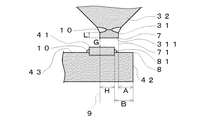
上記中心電極3は、「インコネル600」(商標名)等のニッケル合金からなり、その内部にCuや純Ni又はそれらの複合材料等からなる良熱伝導性金属を有した形態で構成されており、その先端部分が上記絶縁体2の先端から突き出た状態で、上記中心貫通孔21に挿設されている。そして、上記絶縁体2の先端から突き出ている先端部分には、先端面に向うに従って径小となる円錐台部32(高さ0.3mm、径1.0mm)と、該円錐台部32の先端に溶接される中軸チップ31が設けられている。中軸チップ31はIr−5wt%Pt合金で構成されており、厚さ0.6mm、径が0.8mmである。尚、この中軸チップ31は、中心電極母材の円錐台面32の先端に載置され、図2に示すように、レーザー溶接によってストレート部Lを0.2mm以上残した形態で、溶融合金部10を形成して接合される。また、上記中心電極3は、上記絶縁体2の中心貫通孔21の内部に配置されたセラミック抵抗体を経由して、高圧ケーブルが接続されて、高電圧が印加される端子金具に電気的に接続されている(セラミック抵抗体及び端子金具はいずれも図示せず。)。尚、このセラミック抵抗体の両端部は、導電性ガラス層を介して中心電極3及び端子電極とにそれぞれ電気的に接続されている。
【0020】
上記外側電極4はNi合金からなり、主体金具1の先端面に溶接により形成される接合部44によって接合されている。そして、外側電極4は、中心電極3に形成された中軸チップ31と対向する放電面43を有している。尚、外側電極4は、その先端部の温度を低減させ、火花放電による消耗を抑えるために内部にCuや純Ni又はその複合材料等からなる良熱伝導材を有していてもよい。また、外側電極4の放電面43には、中心電極3に形成された中軸チップ31の同軸上に自身の一部が配する形態で外側チップ41が抵抗溶接(レーザー溶接でもよい。)され、接合面外線部に溶融合金部10を形成して外側チップ41が外側電極4に接合されている。そして、中軸チップ31と外側チップ41との両者で放電ギャップ(G)を形成している。上記外側チップ41は貴金属部材であって、Ir合金やPt合金、Rh合金により構成(本実施例では、Pt−Ni系合金)されており、厚さが0.3mm、直径が0.8mmである。
【0021】
ここで、上記外側チップ41を外側電極4に設ける場合の位置関係は、上記のように、その一部が中軸チップ31の同軸上に配され、且つ、図2に示すように、放電面43を延長した平面と外側電極4の先端面42を延長した平面とによって形成される第二交線8と、該第二交線8を放電面43に沿って外側チップ41に接近させてきた場合に、外側チップ41と最初に交わった位置における第二仮想線81と、の間の距離(B)が0.2mm以上となる関係を有する。この関係を満たすことにより、燃焼ガス等といった熱の影響に対する外側チップ41の耐剥離性を向上させることができる。尚、図2は、スパークプラグの横断面形状であることから、第二交線8及び第二仮想線81は点として表現されており、実際は図2の奥から手前の方に延びている。
【0022】
さらに、本実施例のスパークプラグPにあっては、図2に示すように、上述の第二交線8と、主体金具1に形成された内燃機関取付用のネジ11を基準にしたスパークプラグPの仮想軸線6との平行線を、放電ギャップ(G)に対して外側電極4の接合部44と反対側から近づけてきた場合に、中軸チップ31の先端面311を延長した平面と中軸チップ31の側面の延長面(本実施例にあっては、円柱面を形成)との第一交線7(図2は横断面形状であることから、点として表示されており、実際は図2の奥から手前の方に延びている。)とが最初に交わった位置における第一仮想線71と、の間の距離(A)が、上記放電ギャップ(G)との関係において、G≦2A+0.5の関係を有するようにそれぞれ設定されている。
【0023】
図2中に示されている距離(H)は、上記仮想軸線6を、放電ギャップに対して外側電極4の接合部44と反対側から近づけてきた場合に、中軸チップ31の先端面311を延長した平面と中軸チップ31の側面の延長面(本実施例にあっては、円柱面を形成)との第一交線7とが最後に交わる位置における第三仮想線9と、上記第二仮想線81と、の間の距離を表すものである。尚、図2中に示されている距離(A)、(B)及び(H)は、いずれも投影機を使用することで測定可能である。
【0024】
(2)スパークプラグの性能評価
▲1▼放電電圧のバラツキの測定
本試験例のスパークプラグPにおいて、図2における距離(A)及び放電ギャップ(G)を表1に示す値に調整し、実機3000cc、6cyl、A/F=18、アイドリング(600rpm)で10分間、スパークプラグの各サイクルにおける放電電圧(kV)を測定した。そして、各測定値から標準偏差(σ)を求め、放電電圧のバラツキを3σとして求めた。この結果を以下の表1に示す。また、放電ギャップ(G)を1.1mmとした場合に、中軸チップ31の直径及び図2における距離(A)を表2に示す値に変化させた場合の放電電圧(kV)のバラツキを、上記と同じ手法、条件で測定した。この結果を以下の表2に示す。尚、表1において、A=0.2mmという場合は、図2において、外側電極4の先端面42が中軸チップ31の側面よりも右側にある状態でのAの値であるのに対し、A=−0.2mmという場合は、逆に中軸チップ31の側面が外側電極4の先端面42より右側にある状態でのAの値を示す。
【0025】
【表1】

【表2】
▲2▼外側電極の放電面における消耗部の測定
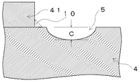
本試験例のスパークプラグにおいて、上記距離(A)を0.4mm、放電ギャップ(G)を0.9mmとし、図2中の距離(H)を0.8mm、0.3mm、0mm、−0.3mmと変化させて、2000cc、6000rpm×W.O.T、300時間後に、中軸チップ31の先端面311の直上に位置する外側電極4(外側チップ41と中軸チップ31が完全に直上で重なる場合は、外側チップ41)の放電面43に生じた消耗部5(図3参照)の最大深さ(C;mm)を求めた。そして、上記距離(H)と最大深さ(C)との関係をプロットしたグラフを図4に示した。尚、図4においてH=−0.3とは、中軸チップ31と外側チップ41が重ならない状態での第二仮想線81と第三仮想線9との間の距離が0.3mmであることを意味する。
【0028】
(3)試験例の効果
表1より、上記距離(A)と放電ギャップ(G)の値が、G≦2A+0.5の関係を満たす場合(表1の太線より下の部分)は、放電電圧のバラツキが4kV以下と小さいのに対し、この関係を満たさない場合(表1の太線より上の部分)では、放電電圧のバラツキが6kV以上と、著しく増加していることが判る。また、表2より、上記距離(A)を0.3〜0.4mmとした場合、中軸チップ31の径が1.2mm以上となると、放電電圧のバラツキが著しく多くなっていることが分かる。更に、図4より、中軸チップ31の直上に外側チップ41がある場合(H=0.8)は、上記消耗部5の最大深さ(C)が小さいのに対し、上記距離(H)が小さくなる、即ち、中軸チップ31と外側チップ41の位置関係のズレが大きくなるにつれ、消耗部5の最大深さ(C)が大きくなり、外側電極4の放電面43の異常消耗が発生していることが判る。
【0029】
尚、本発明においては、前記具体的試験例(スパークプラグPのこと)に示すものに限られず、目的、用途に応じて本発明の範囲内で種々変更したスパークプラグとすることができる。
【0030】
【発明の効果】
本発明の各スパークプラグによれば、中心電極の先端にIrを主体とする中軸チップを設け、且つ、放電ギャップを含め、外側電極の端面と中軸チップとの位置関係を所定の範囲(関係)とすることにより、スパークプラグの寿命延長を可能にすると共に、横飛び火現象や放電電圧のバラツキを防止することができ、未燃焼ガスの排出を抑制することができる。
【図面の簡単な説明】
【図1】本試験例のスパークプラグを示す正面部分断面図である。
【図2】図1のスパークプラグの要部を示す拡大縦断面図である。
【図3】本試験例のスパークプラグの外側電極の先端面付近の拡大縦断面図である。
【図4】図2中における距離(H)と図3中における最大深さ(C)との関係を示したグラフである。
【図5】本発明のスパークプラグの外側電極の先端面付近の拡大縦断面図である。
【符号の説明】
P;スパークプラグ、1;主体金具、11;内燃機関取付用のネジ、2;絶縁体、21;中心貫通孔、3;中心電極、31;中軸チップ、311;中軸チップの先端面、32;円錐台部、4;外側電極、41;外側チップ、42;外側電極の先端面、43;放電面、44;接合部、5;消耗部、6;仮想軸線、7;第一交線、71;第一仮想線、8;第二交線、81;第二仮想線、9;第三仮想線、10;溶融合金部、L;ストレート部、T;テーパー部。[0001]
BACKGROUND OF THE INVENTION
The present invention relates to a spark plug evaluation method and manufacturing method . More specifically, the present invention has a long life, prevents side-fire phenomena and variations in discharge voltage, improves ignitability, and suppresses emission of unburned gas. The present invention relates to a spark plug evaluation method and a manufacturing method .
[0002]
[Prior art]
When the spark plug is used for a long period of time, the center electrode and the outer electrode are consumed due to burning by sparks, and the discharge gap formed between both electrodes is enlarged. As a result, the required voltage required for spark discharge in the gap increases, exceeding the maximum capacity of the power source of the ignition system, or sparking to the end face of the outer electrode and the end face of the metal shell, not the regular gap. May run away. As a result, the combustion gas cannot be reliably ignited, leading to a decrease in durability of the spark plug itself.
[0003]
For this reason, in the conventional spark plug, as the spark consumable material, a central shaft tip made of Pt or a Pt alloy is joined to the tip of the center electrode to suppress the expansion of the discharge gap. By the way, Pt has a melting point of about 1800 ° C., and when a spark plug provided with such a central shaft tip made of Pt or Pt alloy is used for a long time, the tip surface partially melts and sweats on the tip. Grain grows and grows. Then, when such sweat particles are formed on the chip, the expansion of the discharge gap is suppressed, and there is an effect that the discharge voltage is reduced and the side-fire phenomenon is suppressed. However, since the melting point is somewhat low, there is a problem in that the effect of suppressing electrode consumption is limited to some extent by sparks flying and burning of the chip.
[0004]
In view of this, a spark plug using an intermediate shaft tip made of Ir or Ir alloy has been developed as an intermediate shaft tip in order to further suppress the electrode wear than when using the intermediate shaft tip made of Pt or Pt alloy. JP-A-9-219274, etc.). Ir has a melting point of about 2400 ° C., which is higher than that of Pt. Therefore, compared to Pt, the durability of the chip can be improved and burnout due to sparks can be suppressed. As a result, the life of the spark plug can be extended. .
[0005]
[Problems to be solved by the invention]
However, since the melting point of Ir is higher than that of Pt, the durability of the chip can be improved and burnout due to sparks can be suppressed, but sweat particles are hardly formed on the chip. For example, in a spark plug using such an Ir chip, there is no particular problem as long as the lead is cleanly provided between the outer electrode and the electrode, but there may be some deviation in manufacturing. And when there is such a deviation, sweat particles are formed in Pt, so that the expansion of the discharge gap is suppressed and the discharge voltage is stabilized and sparks well, but in Ir, no sweat particles are generated. The voltage tends to increase, and the frequency of jumping to the end face of the metal shell may increase. As a result, ignition of the combustion gas is hindered, unburned gas is discharged, the engine efficiency is reduced, and the exhaust gas may affect the environment.
[0006]
The present invention has been made in view of the above circumstances, has a long life, can prevent a side-fire phenomenon and variation in discharge voltage, improve ignitability, and can suppress discharge of unburned gas. It is an object of the present invention to provide a spark plug evaluation method and manufacturing method .
[0007]
[Means for Solving the Problems]
As a result of studying in view of the above circumstances, the present inventor has provided a central shaft tip mainly composed of Ir at the tip of the center electrode, and the positional relationship between the end surface of the outer electrode and the central shaft tip, including the discharge gap, within a predetermined range. Thus, the present invention has been completed by finding that it is possible to extend the life of the spark plug and to prevent a side-fire phenomenon and variations in discharge voltage.
[0008]
The spark plug evaluation method of the present invention includes an insulator having a center through hole, a center electrode held in the center through hole, and a screw for mounting an internal combustion engine disposed around the insulator in the radial direction. In the spark plug evaluation method , comprising: a metal shell; and an outer electrode having one end joined to the metal shell by a joint and the other end having a discharge surface facing the center electrode with a discharge gap therebetween. The tip that forms the discharge gap has a truncated cone portion that decreases in diameter toward the tip surface, and the tip of the truncated cone surface of the center electrode is mainly composed of Ir and has a diameter of 0.3 to 1. A center shaft tip of 0.0 mm is provided, and the center shaft tip is placed at the tip of the frustoconical surface of the center electrode and joined in a form leaving a straight portion of 0.2 mm or more by laser welding. The discharge surface of the outer electrode is partially coaxial with the center shaft tip, and the end surface of the outer electrode protrudes closer to the center shaft tip than the molten alloy portion formed on the outer line portion of the joint surface. The outer tip is joined, and when the parallel line with the virtual axis based on the screw for mounting the internal combustion engine is approached from the side opposite to the joined portion with respect to the discharge gap, A first imaginary line at a position first intersecting with a first intersecting line formed by a flat surface extending the tip surface of the central shaft tip and an extended surface of the side surface of the central shaft tip, a flat surface extending the discharge surface, and the outer side The distance (A) between the second intersection line formed by the plane extending from the tip end surface of the electrode and the discharge gap (G) satisfy the relationship G ≦ 2A + 0.5, and the discharge gap (G) is 0.85-1. mm, the second intersection line, and when the second intersection line has been approached to the outer chip along the discharge surface, a second imaginary line at a position where the outer chip first intersects, When the distance (B) is 0.2 mm or more and the virtual axis is brought closer to the discharge gap from the side opposite to the joint portion of the outer electrode, the tip surface of the middle shaft tip is extended. a third virtual line at the position where the plane a and the first intersection line intersects the end, the evaluation of the spark plug in which the a second imaginary line, the distance between the (H) is to it Re der least 0.3mm Is the method. The spark plug manufacturing method of the present invention includes the evaluation method of the present invention.
[0009]
In the spark plug of the present invention, the “discharge gap” refers to the tip surface of the central shaft tip and the discharge surface of the outer electrode (the outer tip when an outer tip is provided as described later) in the case of FIG. As shown in FIG. 5, even when the center electrode has a taper portion, the shortest distance between the tip surface of the central shaft tip and the discharge surface of the outer electrode or the outer tip is shown. The value of the discharge gap (G) is not particularly limited, but is usually 0.7 to 1.5 mm, preferably 0.7 to 1.3 mm, and more preferably 0.85 to 1.1 mm. By setting it in such a range, it is preferable that a bridge due to fuel hardly occurs between the discharge gaps, and that ignitability is not lowered and excessive electrode consumption is not caused.
[0010]
In the spark plug of the present invention, the “first intersection line” is formed by a flat surface obtained by extending the tip surface of the central shaft tip and an extended surface of the side surface of the central shaft tip. The first intersection line may be burred when the central shaft tip is cut. In this case, the first intersection line is considered by cutting this burr part. In addition, when the extension surface of the side surface of the central shaft tip that constitutes the first intersection line is cut in the direction of the central axis of the central electrode of the central shaft tip, for example, when both side surfaces of the central shaft tip are substantially parallel It can be expressed as a cylindrical surface.
[0011]
The “second intersection line” in the spark plug of the present invention is formed by a plane obtained by extending the discharge surface of the outer electrode and a plane obtained by extending the tip surface of the outer electrode (see FIG. 2). Since the tip surface of the outer electrode is a cut surface when the coiled rectangular wire is cut to form the outer electrode, a step may be formed on the tip surface. In such a case, the second intersection line is considered based on the tip surface near the discharge surface. In the spark plug of the present invention, the distance (A) can be measured by using a projector.
[0012]
In the spark plug of the present invention, the discharge gap (G) and the distance (A) satisfy the relationship of G ≦ 2A + 0.5, so that the tip that forms the discharge gap of the center electrode is made of Ir or an Ir alloy. It is possible to suppress the consumption of the electrode due to the spark discharge, which is an advantage when the middle shaft tip is used. As a result, it is possible to extend the life of the spark plug and to prevent the side jump phenomenon and the variation in the discharge voltage, which are a concern when Ir or Ir alloy is used as the center shaft tip. In the present invention, the phrase “the main component of the central shaft tip” means that Ir is the component with the highest weight content in the central shaft tip, and the component that occupies 50% by mass or more. Does not mean.
[0013]
In the spark plug of the present invention, a discharge gap may be formed by providing an outer tip on the discharge surface of the outer electrode in order to suppress electrode consumption of the outer electrode. When the outer chip is installed in this way, when the second intersection line and the second intersection line are brought close to the outer chip along the discharge surface, the outer chip is first intersected. The distance (B) between the second imaginary line and the second imaginary line is 0.2 mm or more, preferably 0.3 mm or more, more preferably 0.35 to 0.8 mm (see FIG. 2). If the distance (B) is less than 0.2 mm, the outer tip may be peeled off from the outer electrode by heat, which is not preferable. When the outer tip is formed on the discharge surface by welding, a molten alloy portion composed of an outer tip component and an outer electrode base material component may be formed on the outer edge portion of the joining surface. In such a case, the position where the outer chip itself and the second intersection line first intersect is set as the second imaginary line without considering the molten alloy part.
[0014]
In addition, the outer tip is provided so that a part of the outer tip is coaxial with the middle tip, thereby forming a discharge gap, thereby suppressing abnormal wear on the discharge surface of the outer electrode due to spark discharge, and a spark plug. It is possible to extend the service life. The outer tip may be mainly composed of Ir as in the case of the central shaft tip, and may be composed of a Pt alloy (for example, Pt—Ni or Pt—Ir).
[0015]
In the spark plug of the present invention, the central shaft tip is made of Ir or Ir alloy as described above. The Ir alloy is not particularly limited as long as it contains Ir as a component having the highest weight content. However, when the chip is made of Ir—Pt, Ir—Rh, or Ir—Y 2 O 3 , the temperature is more severe. It is preferable in that the oxidation and volatilization of the chip below is suppressed and the consumption of the electrode is suppressed. Further, as the center axis tip made of these Ir alloys, those having a solid phase point of 1900 ° C. or higher as the phase diagram are preferable for further suppressing the consumption of the electrodes.
[0016]
The diameter of the center shaft tip is 0.3 to 1.0 mm, preferably 0.4 to 0.8 mm. If this diameter is less than 0.3 mm, even if the chip is formed using Ir (Ir alloy), which is a high melting point material, the volume of the chip and the surface on which the discharge gap is formed are small, and the electrode is consumed by spark discharge. Since the suppression effect becomes small, it is not preferable. On the other hand, if it exceeds 1.0 mm, unless the spark plug is used for a special purpose, the surface forming the discharge gap as a chip is large, and the heat of the spark generated in the discharge gap is deprived by the surface ( Therefore, it is feared that misfire will occur and the ignitability deteriorates, which is not preferable.
[0017]
DETAILED DESCRIPTION OF THE INVENTION
Hereinafter, the present invention will be specifically described with reference to test examples.
(1) Configuration of Spark Plug of this Test Example As shown in FIGS. 1 and 2, the spark plug P of this test example is inserted into the
[0018]
The
[0019]
The
[0020]
The
[0021]
Here, the positional relationship of the case where the outer tip 41 to the
[0022]
Further, in the spark plug P of the present embodiment, as shown in FIG. 2, the spark plug based on the above-mentioned
[0023]
The distance (H) shown in FIG. 2 indicates that the tip surface 311 of the central shaft tip 31 is located when the
[0024]
(2) Performance Evaluation of Spark Plug (1) Measurement of Dispersion of Discharge Voltage In the spark plug P of this test example, the distance (A) and the discharge gap (G) in FIG. The discharge voltage (kV) in each cycle of the spark plug was measured at 3000 cc, 6 cyl, A / F = 18, idling (600 rpm) for 10 minutes. Then, the standard deviation (σ) was obtained from each measured value, and the variation in discharge voltage was obtained as 3σ. The results are shown in Table 1 below. Further, when the discharge gap (G) is 1.1 mm, the variation of the discharge voltage (kV) when the diameter of the central shaft tip 31 and the distance (A) in FIG. The measurement was performed using the same method and conditions as above. The results are shown in Table 2 below. In Table 1, when A = 0.2 mm, the value of A in the state where the tip surface 42 of the
[0025]
[Table 1]
[Table 2]
(2) Measurement of consumable part on discharge surface of outer electrode In the spark plug of this test example, the distance (A) is 0.4 mm, the discharge gap (G) is 0.9 mm, and the distance (H) in FIG. Is changed to 0.8 mm, 0.3 mm, 0 mm, and −0.3 mm, and 2000 cc, 6000 rpm × W. O. After 300 hours T, the wear generated on the discharge surface 43 of the outer electrode 4 (the outer tip 41 when the outer tip 41 and the middle tip 31 are directly overlapped) is located immediately above the tip surface 311 of the middle tip 31. The maximum depth (C; mm) of the part 5 (see FIG. 3) was determined. And the graph which plotted the relationship between the said distance (H) and maximum depth (C) was shown in FIG. In FIG. 4, H = −0.3 means that the distance between the second imaginary line 81 and the third imaginary line 9 in a state where the central shaft tip 31 and the outer tip 41 do not overlap is 0.3 mm. Means.
[0028]
(3) Effect of Test Example From Table 1, when the distance (A) and the discharge gap (G) satisfy the relationship of G ≦ 2A + 0.5 (the portion below the thick line in Table 1), the discharge voltage However, when this relationship is not satisfied (the portion above the thick line in Table 1), the variation in the discharge voltage is remarkably increased to 6 kV or more. Further, it can be seen from Table 2 that when the distance (A) is 0.3 to 0.4 mm, the variation in the discharge voltage is remarkably increased when the diameter of the central shaft tip 31 is 1.2 mm or more. Furthermore, from FIG. 4, when the outer tip 41 is directly above the central shaft tip 31 (H = 0.8), the maximum depth (C) of the
[0029]
In addition, in this invention, it is not restricted to what is shown to the said specific test example (it is a spark plug P), It can be set as the spark plug variously changed within the range of this invention according to the objective and the use.
[0030]
【The invention's effect】
According to each spark plug of the present invention, the center shaft tip mainly composed of Ir is provided at the tip of the center electrode, and the positional relationship between the end surface of the outer electrode and the center shaft tip including the discharge gap is within a predetermined range (relationship). By doing so, it is possible to extend the life of the spark plug, to prevent a side-fire phenomenon and variations in discharge voltage, and to suppress discharge of unburned gas.
[Brief description of the drawings]
FIG. 1 is a partial front sectional view showing a spark plug of this test example.
FIG. 2 is an enlarged vertical sectional view showing a main part of the spark plug of FIG.
FIG. 3 is an enlarged longitudinal sectional view of the vicinity of a tip surface of an outer electrode of a spark plug of this test example.
4 is a graph showing the relationship between the distance (H) in FIG. 2 and the maximum depth (C) in FIG. 3;
FIG. 5 is an enlarged longitudinal sectional view of the vicinity of a tip surface of an outer electrode of a spark plug according to the present invention.
[Explanation of symbols]
P; spark plug, 1; metal shell, 11; screw for mounting the internal combustion engine, 2; insulator, 21; center through hole, 3; center electrode, 31; middle shaft tip, 311; Frustoconical part, 4; outer electrode, 41; outer tip, 42; tip surface of outer electrode, 43; discharge surface, 44; junction, 5; consumable part, 6; virtual axis, 7; First imaginary line, 8; second intersection line, 81; second imaginary line, 9; third imaginary line, 10; molten alloy part, L; straight part, T;
Claims (3)
上記中心電極の上記放電ギャップを形成する先端は、先端面に向うに従って径小となる円錐台部を有し、
上記中心電極の上記円錐台面の先端には、Irを主体とし、直径が0.3〜1.0mmの中軸チップが設けられ、
上記中軸チップは、上記中心電極の上記円錐台面の先端に載置され、レーザー溶接によってストレート部を0.2mm以上残した形態で接合されており、
上記外側電極の放電面には、自身の一部が上記中軸チップと同軸上になるとともに、上記接合面の外線部に形成された溶融合金部よりも上記中軸チップ側に自身の端面が突出されて外側チップが接合されており、
上記内燃機関取付用のネジを基準にした仮想軸線との平行線を、上記放電ギャップに対して上記接合部と反対側から接近させてきた場合に、上記中軸チップの先端面を延長した平面と上記中軸チップの側面の延長面とによって形成される第一交線に最初に交わった位置における第一仮想線と、上記放電面を延長した平面と上記外側電極の先端面を延長した平面とによって形成される第二交線と、の間の距離(A)と、上記放電ギャップ(G)とが、G≦2A+0.5の関係を満たし、
上記放電ギャップ(G)が0.85〜1.5mmであり、
上記第二交線と、該第二交線を上記放電面に沿って該外側チップに接近させてきた場合に、上記外側チップと最初に交わった位置における第二仮想線と、の間の距離(B)が0.2mm以上であり、
上記仮想軸線を上記放電ギャップに対して上記外側電極の接合部と反対側から近づけてきた場合に、上記中軸チップの先端面を延長した平面と上記第一交線とが最後に交わる位置における第三仮想線と、上記第二仮想線と、の間の距離(H)が0.3mm以上であればよいとするスパークプラグの評価方法。An insulator having a center through hole, a center electrode held in the center through hole, a metal shell having a screw for mounting an internal combustion engine disposed around the insulator in the radial direction, and one end of the metal shell having one end In an evaluation method of a spark plug comprising: an outer electrode having a discharge surface joined by a joint portion and having the other end side facing the central electrode with a discharge gap therebetween.
The tip that forms the discharge gap of the center electrode has a truncated cone part that decreases in diameter toward the tip surface.
At the tip of the frustoconical surface of the center electrode, a main shaft tip having a diameter of 0.3 to 1.0 mm is provided mainly with Ir,
The middle shaft tip is placed at the tip of the frustoconical surface of the center electrode, and is joined in a form leaving a straight portion of 0.2 mm or more by laser welding,
On the discharge surface of the outer electrode, a part of itself is coaxial with the middle shaft tip, and the end surface of the outer electrode protrudes more toward the middle shaft tip than the molten alloy portion formed on the outer line portion of the joining surface. The outer tip is joined,
When a parallel line with a virtual axis line based on the screw for mounting the internal combustion engine is approached from the side opposite to the joint portion with respect to the discharge gap, a plane obtained by extending the tip surface of the center shaft tip; A first imaginary line at a position first intersecting with a first intersecting line formed by an extended surface of the side surface of the central tip, a plane extending the discharge surface, and a plane extending the tip surface of the outer electrode The distance (A) between the second intersection line formed and the discharge gap (G) satisfy the relationship of G ≦ 2A + 0.5,
The discharge gap (G) is 0.85 to 1.5 mm,
The distance between the second intersection line and the second imaginary line at the position where the outer chip is first intersected when the second intersection line is approached to the outer chip along the discharge surface. (B) is 0.2 mm or more,
When the imaginary axis is brought closer to the discharge gap from the side opposite to the outer electrode joint, the first extended line at the position where the plane where the front end surface of the middle-axis tip is extended and the first intersection line last intersects. three virtual line, the evaluation method of the spark plug in which the a second imaginary line, the distance between the (H) is to it Re der least 0.3 mm.
Priority Applications (1)
| Application Number | Priority Date | Filing Date | Title |
|---|---|---|---|
| JP2001055779A JP4374146B2 (en) | 2000-02-29 | 2001-02-28 | Spark plug evaluation method and manufacturing method |
Applications Claiming Priority (3)
| Application Number | Priority Date | Filing Date | Title |
|---|---|---|---|
| JP2000055003 | 2000-02-29 | ||
| JP2000-55003 | 2000-02-29 | ||
| JP2001055779A JP4374146B2 (en) | 2000-02-29 | 2001-02-28 | Spark plug evaluation method and manufacturing method |
Publications (3)
| Publication Number | Publication Date |
|---|---|
| JP2001319754A JP2001319754A (en) | 2001-11-16 |
| JP2001319754A5 JP2001319754A5 (en) | 2005-10-27 |
| JP4374146B2 true JP4374146B2 (en) | 2009-12-02 |
Family
ID=26586477
Family Applications (1)
| Application Number | Title | Priority Date | Filing Date |
|---|---|---|---|
| JP2001055779A Expired - Lifetime JP4374146B2 (en) | 2000-02-29 | 2001-02-28 | Spark plug evaluation method and manufacturing method |
Country Status (1)
| Country | Link |
|---|---|
| JP (1) | JP4374146B2 (en) |
Families Citing this family (1)
| Publication number | Priority date | Publication date | Assignee | Title |
|---|---|---|---|---|
| JP2005056786A (en) | 2003-08-07 | 2005-03-03 | Denso Corp | Spark plug |
-
2001
- 2001-02-28 JP JP2001055779A patent/JP4374146B2/en not_active Expired - Lifetime
Also Published As
| Publication number | Publication date |
|---|---|
| JP2001319754A (en) | 2001-11-16 |
Similar Documents
| Publication | Publication Date | Title |
|---|---|---|
| JP4092889B2 (en) | Spark plug | |
| JP4965692B2 (en) | Spark plug | |
| JP5249205B2 (en) | Spark plug | |
| US7382085B2 (en) | Spark plug having precious metal tip of specified geometry | |
| JP4302224B2 (en) | Spark plug | |
| JP2003317896A (en) | Spark plug | |
| US9742158B2 (en) | Spark plug | |
| JPH09219274A (en) | Spark plug | |
| JP2003142226A (en) | Spark plug | |
| WO2021111719A1 (en) | Spark plug | |
| US7122948B2 (en) | Spark plug having enhanced capability to ignite air-fuel mixture | |
| JP2002260817A (en) | Spark plug | |
| JP2007207770A (en) | Spark plug | |
| JP2004127916A (en) | Sparking plug and manufacturing method of sparking plug | |
| JP4374146B2 (en) | Spark plug evaluation method and manufacturing method | |
| JP2005135783A (en) | Spark plug | |
| US6573641B2 (en) | Spark plug | |
| JP2000252039A (en) | Spark plug for internal combustion engine | |
| JP4435646B2 (en) | Spark plug | |
| JP4999980B2 (en) | Plasma jet ignition plug | |
| JP6403643B2 (en) | Spark plug | |
| JP4524415B2 (en) | Spark plug | |
| JP4562030B2 (en) | Spark plug | |
| JPH1022053A (en) | Spark plug and its manufacture | |
| JP2005183189A (en) | Spark plug |
Legal Events
| Date | Code | Title | Description |
|---|---|---|---|
| A521 | Written amendment |
Free format text: JAPANESE INTERMEDIATE CODE: A523 Effective date: 20050728 |
|
| A977 | Report on retrieval |
Free format text: JAPANESE INTERMEDIATE CODE: A971007 Effective date: 20060517 |
|
| A131 | Notification of reasons for refusal |
Free format text: JAPANESE INTERMEDIATE CODE: A131 Effective date: 20060523 |
|
| A521 | Written amendment |
Free format text: JAPANESE INTERMEDIATE CODE: A523 Effective date: 20060710 |
|
| A02 | Decision of refusal |
Free format text: JAPANESE INTERMEDIATE CODE: A02 Effective date: 20070116 |
|
| A521 | Written amendment |
Free format text: JAPANESE INTERMEDIATE CODE: A523 Effective date: 20070316 |
|
| RD02 | Notification of acceptance of power of attorney |
Free format text: JAPANESE INTERMEDIATE CODE: A7422 Effective date: 20070319 |
|
| A911 | Transfer to examiner for re-examination before appeal (zenchi) |
Free format text: JAPANESE INTERMEDIATE CODE: A911 Effective date: 20070509 |
|
| A912 | Re-examination (zenchi) completed and case transferred to appeal board |
Free format text: JAPANESE INTERMEDIATE CODE: A912 Effective date: 20070608 |
|
| A521 | Written amendment |
Free format text: JAPANESE INTERMEDIATE CODE: A523 Effective date: 20081204 |
|
| A521 | Written amendment |
Free format text: JAPANESE INTERMEDIATE CODE: A523 Effective date: 20090319 |
|
| A521 | Written amendment |
Free format text: JAPANESE INTERMEDIATE CODE: A523 Effective date: 20090715 |
|
| A01 | Written decision to grant a patent or to grant a registration (utility model) |
Free format text: JAPANESE INTERMEDIATE CODE: A01 |
|
| A61 | First payment of annual fees (during grant procedure) |
Free format text: JAPANESE INTERMEDIATE CODE: A61 Effective date: 20090907 |
|
| FPAY | Renewal fee payment (event date is renewal date of database) |
Free format text: PAYMENT UNTIL: 20120911 Year of fee payment: 3 |
|
| R150 | Certificate of patent or registration of utility model |
Ref document number: 4374146 Country of ref document: JP Free format text: JAPANESE INTERMEDIATE CODE: R150 Free format text: JAPANESE INTERMEDIATE CODE: R150 |
|
| FPAY | Renewal fee payment (event date is renewal date of database) |
Free format text: PAYMENT UNTIL: 20120911 Year of fee payment: 3 |
|
| FPAY | Renewal fee payment (event date is renewal date of database) |
Free format text: PAYMENT UNTIL: 20120911 Year of fee payment: 3 |
|
| FPAY | Renewal fee payment (event date is renewal date of database) |
Free format text: PAYMENT UNTIL: 20130911 Year of fee payment: 4 |
|
| R250 | Receipt of annual fees |
Free format text: JAPANESE INTERMEDIATE CODE: R250 |
|
| R250 | Receipt of annual fees |
Free format text: JAPANESE INTERMEDIATE CODE: R250 |
|
| R250 | Receipt of annual fees |
Free format text: JAPANESE INTERMEDIATE CODE: R250 |
|
| R250 | Receipt of annual fees |
Free format text: JAPANESE INTERMEDIATE CODE: R250 |
|
| R250 | Receipt of annual fees |
Free format text: JAPANESE INTERMEDIATE CODE: R250 |
|
| R250 | Receipt of annual fees |
Free format text: JAPANESE INTERMEDIATE CODE: R250 |
|
| R250 | Receipt of annual fees |
Free format text: JAPANESE INTERMEDIATE CODE: R250 |
|
| R250 | Receipt of annual fees |
Free format text: JAPANESE INTERMEDIATE CODE: R250 |
|
| R250 | Receipt of annual fees |
Free format text: JAPANESE INTERMEDIATE CODE: R250 |
|
| EXPY | Cancellation because of completion of term |