JP4373611B2 - Two stage inflator - Google Patents
Two stage inflator Download PDFInfo
- Publication number
- JP4373611B2 JP4373611B2 JP2000585108A JP2000585108A JP4373611B2 JP 4373611 B2 JP4373611 B2 JP 4373611B2 JP 2000585108 A JP2000585108 A JP 2000585108A JP 2000585108 A JP2000585108 A JP 2000585108A JP 4373611 B2 JP4373611 B2 JP 4373611B2
- Authority
- JP
- Japan
- Prior art keywords
- canister
- generator
- generator canister
- chamber
- gas
- Prior art date
- Legal status (The legal status is an assumption and is not a legal conclusion. Google has not performed a legal analysis and makes no representation as to the accuracy of the status listed.)
- Expired - Lifetime
Links
Images


Classifications
-
- B—PERFORMING OPERATIONS; TRANSPORTING
- B60—VEHICLES IN GENERAL
- B60R—VEHICLES, VEHICLE FITTINGS, OR VEHICLE PARTS, NOT OTHERWISE PROVIDED FOR
- B60R21/00—Arrangements or fittings on vehicles for protecting or preventing injuries to occupants or pedestrians in case of accidents or other traffic risks
- B60R21/02—Occupant safety arrangements or fittings, e.g. crash pads
- B60R21/16—Inflatable occupant restraints or confinements designed to inflate upon impact or impending impact, e.g. air bags
- B60R21/20—Arrangements for storing inflatable members in their non-use or deflated condition; Arrangement or mounting of air bag modules or components
- B60R21/217—Inflation fluid source retainers, e.g. reaction canisters; Connection of bags, covers, diffusers or inflation fluid sources therewith or together
-
- B—PERFORMING OPERATIONS; TRANSPORTING
- B60—VEHICLES IN GENERAL
- B60R—VEHICLES, VEHICLE FITTINGS, OR VEHICLE PARTS, NOT OTHERWISE PROVIDED FOR
- B60R21/00—Arrangements or fittings on vehicles for protecting or preventing injuries to occupants or pedestrians in case of accidents or other traffic risks
- B60R21/02—Occupant safety arrangements or fittings, e.g. crash pads
- B60R21/16—Inflatable occupant restraints or confinements designed to inflate upon impact or impending impact, e.g. air bags
- B60R21/26—Inflatable occupant restraints or confinements designed to inflate upon impact or impending impact, e.g. air bags characterised by the inflation fluid source or means to control inflation fluid flow
- B60R21/268—Inflatable occupant restraints or confinements designed to inflate upon impact or impending impact, e.g. air bags characterised by the inflation fluid source or means to control inflation fluid flow using instantaneous release of stored pressurised gas
- B60R21/272—Inflatable occupant restraints or confinements designed to inflate upon impact or impending impact, e.g. air bags characterised by the inflation fluid source or means to control inflation fluid flow using instantaneous release of stored pressurised gas with means for increasing the pressure of the gas just before or during liberation, e.g. hybrid inflators
-
- B—PERFORMING OPERATIONS; TRANSPORTING
- B60—VEHICLES IN GENERAL
- B60R—VEHICLES, VEHICLE FITTINGS, OR VEHICLE PARTS, NOT OTHERWISE PROVIDED FOR
- B60R21/00—Arrangements or fittings on vehicles for protecting or preventing injuries to occupants or pedestrians in case of accidents or other traffic risks
- B60R21/02—Occupant safety arrangements or fittings, e.g. crash pads
- B60R21/16—Inflatable occupant restraints or confinements designed to inflate upon impact or impending impact, e.g. air bags
- B60R21/26—Inflatable occupant restraints or confinements designed to inflate upon impact or impending impact, e.g. air bags characterised by the inflation fluid source or means to control inflation fluid flow
- B60R21/268—Inflatable occupant restraints or confinements designed to inflate upon impact or impending impact, e.g. air bags characterised by the inflation fluid source or means to control inflation fluid flow using instantaneous release of stored pressurised gas
-
- B—PERFORMING OPERATIONS; TRANSPORTING
- B60—VEHICLES IN GENERAL
- B60R—VEHICLES, VEHICLE FITTINGS, OR VEHICLE PARTS, NOT OTHERWISE PROVIDED FOR
- B60R21/00—Arrangements or fittings on vehicles for protecting or preventing injuries to occupants or pedestrians in case of accidents or other traffic risks
- B60R21/02—Occupant safety arrangements or fittings, e.g. crash pads
- B60R21/16—Inflatable occupant restraints or confinements designed to inflate upon impact or impending impact, e.g. air bags
- B60R21/26—Inflatable occupant restraints or confinements designed to inflate upon impact or impending impact, e.g. air bags characterised by the inflation fluid source or means to control inflation fluid flow
- B60R21/263—Inflatable occupant restraints or confinements designed to inflate upon impact or impending impact, e.g. air bags characterised by the inflation fluid source or means to control inflation fluid flow using a variable source, e.g. plural stage or controlled output
- B60R2021/2633—Inflatable occupant restraints or confinements designed to inflate upon impact or impending impact, e.g. air bags characterised by the inflation fluid source or means to control inflation fluid flow using a variable source, e.g. plural stage or controlled output with a plurality of inflation levels
Landscapes
- Engineering & Computer Science (AREA)
- Mechanical Engineering (AREA)
- Physics & Mathematics (AREA)
- Fluid Mechanics (AREA)
- Air Bags (AREA)
- Feeding, Discharge, Calcimining, Fusing, And Gas-Generation Devices (AREA)
Abstract
Description
(発明の背景)
(発明の分野)
本発明は、概してガス発生器を含む膨張装置に関するものであり、より詳細には異なる率およびレベルのガスを選択的に放出することができるとともに、エアバックやそのような種類の膨張可能な安全抑制装置を、異なるセンサ入力にしたがって異なる出力レベルで膨張することを可能とする二段階膨張器に関する。
【0001】
(関連技術の詳細)
近年、乗客の大きさ、位置、シートベルトの使用および衝突時の自動車の速度にしたがってエアバック抑制システムのような安全装置の膨張率と膨張量とを制御することに対する需要が高まっている。
【0002】
乗員に対して最適な保護を提供するために、エアバック膨張器から出力の異なるレベルが必要とされる。たとえば、大柄の人がベルトをしていない状態で高速度に衝突した場合、最も好適な保護を与えるためにはエアバックを急速かつ完全に膨らませることが必要になる。小柄な乗客あるいは正規の位置にいない乗客が低い速度で衝突した場合、不注意に乗客を傷つけないが保護を提供するために十分な膨張を行うため、より低い速度のゆっくりとして膨張が必要となる。
【0003】
二段階の膨張を達成するために、トロウブリッジ(Trowbridge)らによる米国特許3,773,353号においては、2つの火薬を分離し、低速度の膨張が必要な場合にはその一方を点火し、高速度の衝突時にはその両方を点火することにより、そのような状況において必要なエアバックの急速な膨張と展開とを達成することが提案されている。この装置においては、非毒性のガスにより圧力充填されたリザーバ内に火薬が配置されている。2つの火薬のうち第1の火薬が着火した場合には、ピストンとロッドとからなるタイプの構成により穿孔されたバーストプレートにより、ハウジングは被覆される。しかしながらこの構成は、比較的複雑になるという欠点を有しており、それゆえ、相対的に高価になる。たとえば、少なくとも3つのバーストプレートからなる構成が必要となる。また、各火薬は、内部のハウジングとそれぞれが破壊可能な蓋とにより、リザーバとリザーバガスとから隔離されている。
【0004】
アレマン(Allemann)による米国特許3,905,515号においては、2つの分離された火薬を用いるとともに、非毒性ガスを圧力保存したチャンバ内に火薬を配置する構成の他の2段階の膨張器アッセンブリが提案されている。しかしながら、この構成は特許3,773,353号のものよりもさらに複雑である。この構成においては、バーストディスクの一部が、2つの火薬のうち一方あるいは両方を爆発させるガスの流出を部分的に絞る、排気通路の中に突出した摺動可能なシャトル弁部材の頭部を形成する。
【0005】
二段階膨張器の設計に関しては、たとえば、膨張器アッセンブリを棄てるために取り除いたり、自動車全体を解体したりするときのように、使用後における膨張器アッセンブリの処理可能性が重要である。二段階装置においては、1つのガス発生器が点火された場合、たとえば低速度の衝突に対しては、他の発生器が点火可能状態のままであるので、たとえば取り外しあるいは自動車の保管の間における潜在的な安全性に関する問題を提起する。万一点火した場合には、第2の発生器は高温高圧ガスを発生する。
【0006】
このような理由により、第1の発生器のみが展開された場合であっても、第2の発生器も、瞬間衝突の後であって、衝突後たとえば100ミリセカンドまでの衝突事故の時間内に点火することが好ましい。この場合、エアバック内に可能な限り小さな出力を付与することにより、バックが再び膨張して乗客に衝撃を与えないようにすることが重要である。
【0007】
ブッチャナンによる欧州特許公開第800965号では、メインチャンバを形成する球形ハウジングと、メインチャンバに設置される2つの加熱装置とを開示している。これらの加熱装置は、広範囲の性能を達成するために連続して起動される。しかしながら、各加熱装置は、メインチャンバ内のガスから装置を隔離するための防護殻により覆われている。その結果、加熱装置内の圧力は、防護殻を破壊するのに十分なレベルまで上昇されなければならない。また、膨張器に一般的に用いられているガス発生材料(generant)の性質のため、ガス発生材料は、発熱および/またはガス発生を引き起こしながら、高圧力下において急速に燃焼する。この膨張器が二重モードで用いられるとともに単一の加熱装置のみが低速度の衝撃に対応して起動された場合、他のガス発生器が故意あるいは不測の状態で点火すると、エアバックが再び膨らむことが十分起こりえる。
【0008】
また、加熱装置は貯蔵ガスから隔離されているので、余分な容積が貯蔵ガスにより占有され、膨張器全体を小さくすることができる。米国特許第5,582,428号および第5,630,619号は同様の膨張器を開示している。しかしながら、これらの膨張器は複数のバーストディスクと複数の容器とを有しているため不必要に複雑であり、さらに未使用の発生器が遅れて点火することによりエアバックが再び膨らんでしまう可能性がある。さらに、上記したトロウブリッジらおよびアレマンにより開示された装置は、ブッチャナンにより開示された装置と同様の欠点がある。
【0009】
したがって、ユニットを分解して廃棄することができるように、破壊されたエアバックを再び膨らませずに第1の発生器の点火後に第2の発生器を点火させることが可能な、低コスト、コンパクト、かつシンプルな二段階膨張器が必要である。
【0010】
(発明の概要)
それゆえ、本発明は、従来技術の問題点を解決し、二段階性能を効率的に発揮することが可能な、低コストかつ安全な二段階膨張装置を提供することを目的とする。
【0011】
本発明は、エアバックを再び膨らませることなく、単一の発生器のみの出力が必要な場合、発生器の一方あるいは両方を点火させることにより、エアバックを最初に膨張させるとともに第2の発生器を連続して点火させることが可能な二段階膨張器を提供することを目的とする。
【0012】
さらに、本発明は、貯蔵ガス用の内部容積を最大化するとともに、容易に輸送でき、膨張器アッセンブリに簡易に取り付けることが可能な単一発生器キャニスタサブアッセンブリを備える二段階膨張器を提供することを目的とする。
【0013】
さらに、本発明は、衝突事故において第2の発生器を分解することにより、自動車事故の後における乗員の安全性を改善する二段階膨張器を提供することを目的とする。
【0014】
さらに、本発明は、個々のレベルにおけるガス発生器の負荷をシステム要求に依存させて独立して調整することにより、適用性を最大化することができる二段階膨張器を提供することを目的とする。
【0015】
本発明は、アッセンブリのコストとサイズとを最小化する二段階膨張器を提供することを目的とする。
【0016】
本発明のこれらの目的と他の目的とは、自動車安全抑制装置を膨張させる二段階膨張装置において、所定量が貯蔵不活性ガスを含むチャンバと自動車安全抑制装置へ加圧ガスを導く排出口とを有する外側ハウジングと、上記チャンバに設置されるとともに、ガス発生材料を受容する空洞を形成する第1のキャニスタ壁と上記空洞と上記チャンバとを連通させる少なくとも1つの開口とを有する第1の発生器キャニスタと、チャンバに設置されるとともにガス発生材料を受容する空洞を形成する第2のキャニスタ壁と上記空洞と上記チャンバとを連通させる少なくとも1つの第2の開口とを有する第2の発生器キャニスタとを備える二段階膨張装置を提供することにより達成される。重要であるのは、第1の発生器キャニスタと第2の発生器キャニスタとの両方の内部にあるガス発生器は、貯蔵不活性ガスに露出されており、ガス発生材料の点火により各空洞内において予期せぬ圧力上昇がおこることを防止するとともに、貯蔵ガスのための内容積を最大化することにより、膨張器全体の大きさを最小化することである。二段階膨張装置は、少なくとも1つの点火器を備えており、該点火器は第1および第2の発生器キャニスタ内のガス発生材料を点火する。第1の発生器キャニスタと第2の発生器キャニスタとのうち少なくとも1つのガス発生材料は、低圧下では効率よく燃焼することができないタイプのものである。その結果、連結された自動車安全抑制装置、すなわちエアバックを再び膨らませることなく、発生器キャニスタのうち1つの中にある未点火のガス発生材料を、他の発生器キャニスタの点火に連続させて点火することが可能となる。
【0017】
好ましくは、第1および第2の発生器キャニスタのそれぞれは、点火器とガス発生材料との間の空洞に設置された増圧火薬を含んでいる。少なくとも1つの第1の開口と、少なくとも1つの第2の開口とは、増圧火薬の1つに隣接して配置された増圧開口と、少なくとも1つの点火器とを備えている。好ましくは、少なくとも1つの第1の開口と少なくとも1つの第2の開口とのそれぞれは、各発生器キャニスタに沿って軸方向に延びる複数の開口を含む。複数の開口は、2本の開口列とすることが可能である。第1の発生器キャニスタは、ガス発生材料を第1の所定量受容することが可能であり、一方第2の発生器キャニスタは、ガス発生材料を第1の所定量以上あるいは未満である第2の所定量受容することが可能である。
【0018】
本発明は、自動車安全抑制装置を膨張させる二段階膨張装置において、第1の所定圧力レベルにある貯蔵不活性ガスを所定量含むチャンバと自動車安全抑制装置へ加圧ガスを導く排出口とを有する外側ハウジングと、上記排出口に近接して配置されるとともに、チャンバ内の圧力が第1の所定圧力レベルよりも大きな第2の所定圧力レベルに達すると分解するように調整されたバーストディスクと、上記チャンバに設置されるとともに、ガス発生材料を受容する空洞と上記空洞と上記チャンバとを連通させるように上記キャニスタ内に形成される少なくとも1つの開口とを有する第1の発生器キャニスタと、チャンバに設置されるとともにガス発生材料を受容する空洞と各空洞と上記チャンバとを連通させる少なくとも1つの第2の開口とを有する第2の発生器キャニスタとを備える二段階膨張装置を提供することにより達成される。二段階膨張器は、第1および第2の発生器キャニスタ内のガス発生材料を点火する少なくとも1つの点火器を備える。重要であるのは、二段階膨張装置は、第1の発生器キャニスタ内のガス発生材料を点火して燃焼させることにより、第2の発生器キャニスタ内のガス発生材料を不注意に点火してしまうことを防止する点火防止構成を備えていることである。点火防止構成は少なくとも1つの第1の開口および少なくとも1つの第2の開口から十分な距離をおいて配置されており、少なくとも1つの第1の開口からのガス流れを少なくとも1つの第2の開口に到達する前に、チャンバ内の内部ガスにより十分冷却することができる。好適な実施形態では、第1および第2の発生器キャニスタは、共通の第1の方向に対向する第1の側面と、第1の方向の実質的に反対である共通の第2の方向に対向する第2の側面とを含んでいる。点火防止構成は、第1の発生器キャニスタの第1の側面に少なくとも1つの第1の開口を含んでいるが、第1の発生器キャニスタの第2の側面には開口が無い。点火防止構成は、第2の発生器キャニスタの第2の側面に少なくとも1つの第2の開口を含んでいるが、第2の発生器キャニスタの第1の側面には開口が無い。また、共通のベースに配置された2つの発生器の間には、第2の発生器の不注意の点火を防止するためのシールが存在する。
【0019】
本発明は、自動車安全抑制装置を膨張させる膨張装置において、貯蔵不活性ガスを所定量受容するチャンバと、チャンバ内に設置されたユニット型ガス発生器キャニスタアッセンブリとを有しているとともに、ガス発生材料を受容する第1の発生器キャニスタを有している外側ハウジングと、ガス発生材料を受容するとともに上記第1の発生器キャニスタに近接して配置された第2の発生器キャニスタと、第1および第2の発生器キャニスタの両方の端部に接続された共通ベースとを備えており、共通ベースは外側ハウジングに接続されている。膨張装置は、第1の発生器キャニスタ内のガス発生材料を点火するように第1の発生器キャニスタの端部の共通ベースに近接して配置された第1の点火器と、第2の発生器キャニスタ内のガス発生材料を点火するように第2の発生器キャニスタの端部の共通ベースに近接して配置された第2の点火器とを備えている。好ましくは、第1の発生器キャニスタと第2の発生器キャニスタとのそれぞれはシリンダ形状であり、共通ベースは、第1および第2の発生器キャニスタからユニット型ガス発生器アッセンブリの2つの対向する側面まで横断するように外側に延びる取り付けフランジを備えている。外側ハウジングは円形の横断面であることが好ましく、共通ベースは外側ハウジングのチャンバ内に配置されている。外側ハウジングは、チャンバの端部近辺に設置されたエンドキャップと、チャンバと反対側の端部に形成される排出口とを備えており、これによりバーストディスクを排出口の近辺に配置するとともに、所定圧力レベルに達したときにチャンバ内で圧力分解させることができる。好ましくは、第1の点火器と第2の点火器とはエンドキャップ上に配置される。また、第1の発生器キャニスタと第2の発生器キャニスタとのそれぞれは、ガス発生材料をチャンバ内の貯蔵不活性ガスに露出する複数の開口を備えており、第2のガス発生材料の点火により空洞内に好ましくない圧力上昇が発生することを防止している。
【0020】
(好適な実施形態の詳細な説明)
図1aには本発明の二段階膨張装置あるいは膨張器が、参照符号10により全体的に示されており、膨張器10は、自動車安全抑制器、すなわちエアバックを、例えば高速度の自動車衝突時には高レベルかつ高膨張率にて膨張させる一方、低速度の衝突時には低レベルかつ低膨張率で膨張させる。二段階膨張器10はチャンバ14を形成する外側ハウジング12と、チャンバ14に配置されたユニット型ガス発生器キャニスタアッセンブリ16と、ユニット型ガス発生器キャニスタアッセンブリ16内のガス発生材料の燃焼を開始させる第1および第2の点火器18・20とを概して備えている。
【0021】
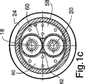
図1a〜1cに示すように、外側ハウジング12は、シリンダ形状のハウジング部分22と、チャンバ14を被覆するように取り囲むハウジング部分22の一端に設置されたエンドキャップ24と、ハウジング部分22の反対側の端部に設置された排出ピース26とを備えている。排出ピース26は、チャンバ14の内部に延びており、チャンバ14からエアバック(図示せず)の中へガスを導く排出口28を備えている。ディフューザ30は、排出口28の上流側ですぐ近くに配置されており、バーストディスク32は、ディフューザ30の上流側ですぐ近くに配置されている。バーストディスク32は所定圧力を加えることにより分解するように調整されているので、排出口28を通じてチャンバ14からエアバックに加圧されたガスを流すことができる。これ以降に詳述するユニット型ガス発生器キャニスタ16を取り付けも含めて、二段階膨張器10を組み立てた後、エンドキャップ24が気密的に密閉される。充填ポート34がエンドキャップ24に設けられているので、アルゴン、ヘリウム等の選択された非毒性ガスをチャンバ14へ圧力下で容易に補充することができる。
【0022】
図1a,1cおよび図2a〜2cに示すように、ユニット型ガス発生器キャニスタアッセンブリ16は、第1のキャニスタ壁38により形成された第1の発生器キャニスタ36と、第2のキャニスタ壁42により形成された第2の発生器キャニスタ40とを備えている。第1および第2の発生器キャニスタ36・40は、概してシリンダ形状であり、各空洞44および46を形成している。48で示されているガス発生材料は、点火時にガスを発生するものであり、各空洞44・46に配置されている。二段階性能を達成するために、たとえば低速度の衝突時において、第2の発生器キャニスタ40を点火して燃焼させずに、低減されたレベルおよび割合でエアバックを膨張させるのに十分な量のガス発生材料48が、第1の発生器キャニスタ36に配置される。第2の発生器キャニスタ40は、たとえば高速度の衝突時において、第1の発生器キャニスタ36とともに点火してより高い膨張レベルと所望の割合を得ることができる量のガス発生材料48を備えている。ガス発生材料48は、各空洞44・46内においてバイアススプリング50とスプリングプレート52とにより固定されている。第1および第2の発生器キャニスタ36・40は、第1の点火器18および第2の点火器20に隣接する空洞の一端に設置された増圧ハウジング56内に増圧火薬54を備えている。増圧火薬54により、点火器18・20を用いてガス発生材料48を効率的かつ確実に点火させることができる。
【0023】
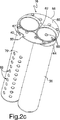
ユニット型ガス発生器キャニスタアッセンブリ16は、最終アッセンブリの前に容易に輸送することができるような完全なユニット型アッセンブリとして有利に形成される。特に、第1および第2の発生器キャニスタ36・40は、互いにアーチ形状となるように設置されており、図2a〜図2cにおいて明瞭に示すように、共通ベース58に接続されている。第1および第2の発生器キャニスタ36・40の外側の合計幅と実質的に等しい直径に共通ベース58を形成することにより、ユニット型ガス発生器キャニスタアッセンブリ16のサイズを最小化することができる。共通ベース58は2つの取り付けフランジ60を備えており、該取り付けフランジ60は、第1および第2の発生器キャニスタ36・40のそれぞれの一端を摺動可能に受容するように形成された中心開口62から径方向の外側に向かって延びている。共通ベース58は、第1および第2の発生器キャニスタ36・40を支持するとともに、それらの接続位置を提供するように中心開口62の周りに延びるサポートリング64を備えている。第1および第2の発生器キャニスタ36・40は、たとえばろう付けや溶接により、共通ベース58と、特にサポートリング64とに接続することが可能である。その結果、ユニット型ガス発生器キャニスタアッセンブリ16は、内蔵型のものとなり、よりコンパクトなものとなる一方、容易に輸送することができるとともに外側ハウジング12に取り付けることができる。
【0024】
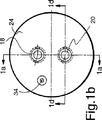
図1a,1cおよび1dに示すように、あらゆる従来の方法で共通ベース58をエンドキャップ24に接続することにより、ガス発生器アッセンブリ16はチャンバ14に設置される。シール75は、第2の発生器を不注意に点火することをより確実に防止するように、共通ベース58とエンドキャップ24との間に設置されている。第1および第2の点火器18・20は、それぞれエンドキャップ24の内側部に設置されており、それぞれ第1および第2の発生器36・40の中に延びている。第1および第2の点火器18・20は、点火器に点火信号を伝達する適切な電気配線と接続するためのコネクタを備えている。
【0025】
第1および第2の発生器キャニスタ36・40は、それぞれのキャニスタ壁に形成された複数の開口を備えているので、これにより各空洞はチャンバ14に直接つながっている。特に、図2bおよび図2cに示すように、第1の発生器キャニスタ36はユニット型ガス発生器キャニスタアッセンブリ16の第1の側面70に配置された複数の開口66を備えており、一方第2の発生器キャニスタ40はユニット型ガス発生器キャニスタアッセンブリ16の第2の側面72に配置された複数の開口68を備えている。好適な実施形態では、図2bおよび図2cに示すように、第1の発生器キャニスタ36に形成された第1の複数の開口66は、キャニスタ36にそって軸方向に延びる2本の開口の列を含んでいる。複数の開口66は、増圧火薬54からの圧力を制御する一対の増圧開口67を含んでいる。同様に、複数の開口68は、増圧開口69を備える第2の発生器キャニスタ40の第2の側面に沿って延びる2本の開口列を含んでいる。
【0026】
複数の開口66および68は、第1および第2の発生器キャニスタ36・40内のガス発生材料を、チャンバ14内の現在の条件に露出していることも重要である。第1および第2の発生器キャニスタ36・40内に配置されたガス発生材料48は、ガス発生材料とキャニスタ壁との間に、増圧部材とガス発生材料との両方の初期および連続点火燃焼の間にキャニスタのそれぞれの空洞内での圧力上昇を引き起こすような他のケーシング、被覆物、あるいは包装材を備えていない。重要であるのは、第2の発生器キャニスタ40が、エアバックを再び膨らませることなく第1の発生器キャニスタ36の点火から所定時間後に点火するように設定されていることである。たとえば、低速度の衝突においては、第1の発生器キャニスタ36が点火されると、第1の発生器キャニスタ36により生成される高温ガスによりチャンバ14の中がさらに加圧される。ガス発生材料48が燃焼すると、ガスは即座に複数の開口66を通じてチャンバ14の中に放出され、ガスの量が増加するとともに温度も上昇するので、チャンバ14内の圧力が上昇する。所定の圧力まで上昇すると、バーストディスク32が分解し、チャンバ14内のガスが排出口28を通じてエアバック内に流れ込む。続いて、不注意の点火と乗客に損傷を与えることを防止するという安全上の目的のため、第2の発生器キャニスタ40を点火することが望ましい。この2次点火はエアバックを再び膨らませることなく行われる。本発明の二段階膨張器10によれば、第2の発生器キャニスタ40は2つの特定の理由によりエアバックを再び膨らませることなく点火される。第1に、第1および第2の発生器キャニスタ36・40の両方のガス発生材料48は、直接チャンバ14に露出されている。その結果、第2の発生器キャニスタ40が第2の点火器20により点火されると、チャンバ14は(最初の展開からおおよそ100ミリセカンド後に)本質的に減圧される。第2の発生器キャニスタ40により生成されるガスとチャンバ14内の既に減圧されたガスの量を合計しても、エアバックを再び膨らませるためには不十分である。第2に、ガス発生材料48は、低圧の環境下においては、効率的に燃焼することができない、すなわち高い割合でガスを発生するタイプのものである。ガス発生材料48により生成される初期のガスは、複数の開口により受容されず、さらに低圧チャンバ14の中に放出されるので、第2の発生器キャニスタ40内のガス発生材料はエアバックを再び膨らませるために十分な量のガスを生成することができない。たとえば、ガス発生材料48は、この中に援用として全体が含まれている米国特許第5,726,382号に記載されているようなタイプの材料とすることができる。
【0027】
二段階膨張装置10は、第1の発生器キャニスタ36内のガス発生材料48を点火して燃焼させることにより、第2の発生器キャニスタ40内のガス発生材料が不注意に点火してしまうことを防止する点火防止構成を備えていることである。第1の発生器キャニスタ36を点火する間は、ガス発生材料48の燃焼により生成されるガスが非常に高温で存在する。この高温ガスは、複数の開口66を通じてチャンバ14内に流れ込み、チャンバ14内の不活性ガスと混合する。第1の発生器キャニスタ36からの高温ガスは、第2の発生器キャニスタ40内のガス発生材料48の温度誘導点火を引き起こす可能性があることが知られている。しかしながら、本発明の点火防止構成74によれば、第1の発生器キャニスタ36に形成された複数の開口66と第2の発生器キャニスタ40に形成された複数の開口68との間に長い流れ通路を形成することにより、第2の発生器キャニスタ40内のガス発生材料48の温度誘導点火を防止する。特に、点火防止構成は、第1の発生器キャニスタ36における複数の開口66を、ユニット型ガス発生器キャニスタアッセンブリ16の外周面に沿って、第2の発生器キャニスタ40に形成された複数の開口68から十分な距離をおいて配置しているので、複数の開口66からのガス流れを、第2の発生器キャニスタ40に形成された複数の開口68に到達する前に、チャンバ14内の不活性ガスにより十分冷却することができる。
【0028】
好適な実施形態では、図2bおよび図2cに示すように、複数の開口66が第1の発生器キャニスタ36の第1の側面70上に形成されているが、キャニスタ36の第2の側面72には開口が形成されていない。一方、複数の開口68は、複数の開口66と反対の方向となるように第2の発生器キャニスタ40の第2の側面に形成されており、第2の発生器キャニスタ40の第1の側面70には開口が無い。したがって、複数の開口66からのガス流れは、複数の開口68に進入する前に、ユニット型ガス発生器アッセンブリ16の外周面あるいは端部に沿って、流れなければならない。その結果、本発明の点火防止構成74は、他方のキャニスタの開口に到達する前に高温ガスを冷却するための長い冷却通路を形成するので、チャンバ14内の低温の不活性ガスにより、第1の発生器キャニスタ36により生成される高温ガスを、第2の発生器40内のガス発生材料48の温度誘導引火が起きないような低い温度まで冷却することができる。さらに、共通ベース58とエンドキャップ24との間に設置されたシール75は、第1の発生器からの高温のガス流れが第2の発生器へ流れることを防止する。これにより、第2の発生器が不注意に点火することをより確実に防止する。その結果、この構成により、安全性、信頼性がより高い二段階膨張装置10を提供することができる。もちろん、開口の間の距離が、未点火のキャニスタを不注意に温度的に誘導引火することを防止することができるよう、高温のガスを適切に冷却することができるのに十分である限り、複数の開口66と複数の開口68とは、各キャニスタの他の位置に形成することも可能である。
【図面の簡単な説明】
【図1a】 本発明の膨張装置の断面図であり、本発明のユニット型ガス発生器キャニスタアッセンブリの平面1a−1aに沿う断面図を図1bに示す。
【図1b】 図1aの膨張装置の端部の側面図であり、点火器の位置を示す。
【図1c】 図1aの膨張装置の平面1c−1cに沿う断面図である。
【図1d】 本発明の膨張装置の図1bにおける1d−1dに沿う部分断面図である。
【図2a】 本発明のユニット型ガス発生器キャニスタアッセンブリの断面図である。
【図2b】 本発明のユニット型ガス発生器キャニスタアッセンブリの側面を示す斜視図である。
【図2c】 本発明のユニット型ガス発生器キャニスタアッセンブリにおける、アッセンブリの反対側の側面を、逆転させた位置で示す斜視図である。(Background of the Invention)
(Field of Invention)
The present invention relates generally to an expansion device that includes a gas generator, and more particularly, can selectively release different rates and levels of gas, as well as airbags and such types of inflatable safety. It relates to a two-stage inflator that allows the suppression device to be expanded at different output levels according to different sensor inputs.
[0001]
(Details of related technology)
In recent years, there has been an increasing demand for controlling the rate of expansion and the amount of expansion of safety devices such as airbag suppression systems according to passenger size, position, seat belt usage and vehicle speed during a collision.
[0002]
Different levels of output from the airbag inflator are required to provide optimal protection for the occupant. For example, if a large person collides at high speed without a belt, the airbag must be inflated quickly and completely to provide the best protection. If a small passenger or a non-legal passenger collides at a low speed, a slow expansion at a lower speed will be required to inadvertently hurt the passenger but provide sufficient expansion to provide protection .
[0003]
To achieve a two-stage expansion, US Pat. No. 3,773,353 by Trowbridge et al. Separates two explosives and ignites one of them when low speed expansion is required. It has been proposed to ignite both during high speed collisions to achieve the rapid inflation and deployment of the airbag required in such situations. In this device, explosives are placed in a reservoir that is pressure filled with a non-toxic gas. When the first of the two explosives is ignited, the housing is covered with a burst plate that is perforated with a piston and rod type configuration. However, this arrangement has the disadvantage of being relatively complex and is therefore relatively expensive. For example, a configuration including at least three burst plates is required. Each explosive is isolated from the reservoir and the reservoir gas by an internal housing and a lid that can be destroyed.
[0004]
In U.S. Pat. No. 3,905,515 by Allemann, another two-stage inflator assembly that uses two separate explosives and places the explosive in a chamber that is pressure-stored with non-toxic gases. Has been proposed. However, this configuration is even more complicated than that of patent 3,773,353. In this configuration, a portion of the burst disk has a slidable shuttle valve member head protruding into the exhaust passage that partially throttles the outflow of gas that explodes one or both of the two explosives. Form.
[0005]
Regarding the design of a two-stage inflator, the ability to handle the inflator assembly after use is important, for example when removing the inflator assembly for disposal or dismantling the entire vehicle. In a two-stage device, if one gas generator is ignited, for example for a low-speed collision, the other generator remains in an ignitable state, for example during removal or car storage Raise potential safety issues. In the unlikely event of ignition, the second generator generates hot high pressure gas.
[0006]
For this reason, even if only the first generator is deployed, the second generator is also after the momentary collision and within the time of the collision accident up to, for example, 100 milliseconds after the collision. Is preferably ignited. In this case, it is important to give the smallest possible output in the airbag so that the bag does not inflate again and impact the passenger.
[0007]
EP 800965 by Butchanan discloses a spherical housing forming a main chamber and two heating devices installed in the main chamber. These heating devices are activated continuously to achieve a wide range of performance. However, each heating device is covered by a protective shell for isolating the device from the gas in the main chamber. As a result, the pressure in the heating device must be increased to a level sufficient to destroy the protective shell. Also, due to the nature of the generant commonly used in expanders, the gas generating material burns rapidly under high pressure while causing heat generation and / or gas generation. If this expander is used in dual mode and only a single heating device is activated in response to a low-velocity impact, the air bag will turn on again if other gas generators are ignited intentionally or unexpectedly. Swelling can happen enough.
[0008]
Also, since the heating device is isolated from the stored gas, an extra volume is occupied by the stored gas, and the entire expander can be made smaller. U.S. Pat. Nos. 5,582,428 and 5,630,619 disclose similar expanders. However, these inflators are unnecessarily complicated because they have a plurality of burst disks and a plurality of containers, and the airbag can be inflated again by igniting an unused generator with a delay. There is sex. Furthermore, the device disclosed by Troubridge et al. And Alleman described above has the same disadvantages as the device disclosed by Butchanan.
[0009]
Therefore, a low cost, compact, capable of igniting the second generator after ignition of the first generator without reinflating the destroyed airbag so that the unit can be disassembled and discarded A simple two-stage inflator is required.
[0010]
(Summary of Invention)
SUMMARY OF THE INVENTION Therefore, an object of the present invention is to provide a low-cost and safe two-stage expansion device that can solve the problems of the prior art and can efficiently exhibit the two-stage performance.
[0011]
If the output of only a single generator is required without inflating the airbag again, the present invention inflates the airbag first and second generation by igniting one or both of the generators. It is an object of the present invention to provide a two-stage expander capable of igniting the expander continuously.
[0012]
Furthermore, the present invention provides a two-stage inflator with a single generator canister subassembly that maximizes the internal volume for stored gas and that can be easily transported and easily attached to the inflator assembly. For the purpose.
[0013]
It is a further object of the present invention to provide a two-stage inflator that improves occupant safety after an automobile accident by disassembling the second generator in a collision accident.
[0014]
It is a further object of the present invention to provide a two-stage expander that can maximize applicability by independently adjusting the gas generator load at each level depending on system requirements. To do.
[0015]
The present invention seeks to provide a two-stage inflator that minimizes the cost and size of the assembly.
[0016]
These and other objects of the present invention include: a two-stage expansion device for inflating a vehicle safety restraint device, wherein a predetermined amount of a chamber containing a stored inert gas and a discharge port leading pressurized gas to the vehicle safety restraint device; A first canister wall disposed in the chamber and forming a cavity for receiving a gas generating material, and at least one opening communicating the cavity with the chamber. A second canister having a canister, a second canister wall which is installed in the chamber and forms a cavity for receiving gas generating material, and at least one second opening communicating the cavity and the chamber This is accomplished by providing a two-stage inflator with a canister. Importantly, the gas generator inside both the first generator canister and the second generator canister is exposed to stored inert gas and is ignited in each cavity by ignition of the gas generating material. Is to minimize the overall size of the inflator by preventing an unexpected pressure increase and maximizing the internal volume for the stored gas. The two-stage expansion device includes at least one igniter that ignites the gas generant material in the first and second generator canisters. At least one gas generating material of the first generator canister and the second generator canister is of a type that cannot efficiently burn under low pressure. As a result, the unignited gas generant material in one of the generator canisters can be continued to the ignition of the other generator canister without re-inflating the connected vehicle safety restraint device, ie the airbag. It becomes possible to ignite.
[0017]
Preferably, each of the first and second generator canisters includes a boosted explosive located in a cavity between the igniter and the gas generating material. The at least one first opening and the at least one second opening comprise a boosting opening disposed adjacent to one of the boosting explosives and at least one igniter. Preferably, each of the at least one first opening and the at least one second opening includes a plurality of openings extending axially along each generator canister. The plurality of openings can be two opening rows. The first generator canister can receive a first predetermined amount of gas generating material, while the second generator canister receives a second that is greater than or less than the first predetermined amount of gas generating material. It is possible to accept a predetermined amount of.
[0018]
The present invention relates to a two-stage expansion device for inflating a vehicle safety restraint device, having a chamber containing a predetermined amount of stored inert gas at a first predetermined pressure level and a discharge port for leading pressurized gas to the vehicle safety restraint device. An outer housing and a burst disk positioned proximate to the outlet and adjusted to disassemble when the pressure in the chamber reaches a second predetermined pressure level greater than the first predetermined pressure level; A first generator canister installed in the chamber and having a cavity for receiving a gas generating material; and at least one opening formed in the canister to communicate the cavity and the chamber; And a cavity for receiving the gas generating material, and at least one second opening for communicating each cavity with the chamber. It is achieved by providing a two-stage expander and a second generator canister. The two-stage expander includes at least one igniter that ignites the gas generating material in the first and second generator canisters. Importantly, the two-stage expansion device inadvertently ignites the gas generating material in the second generator canister by igniting and burning the gas generating material in the first generator canister. It is provided with the ignition prevention structure which prevents that. The anti-ignition arrangement is disposed at a sufficient distance from the at least one first opening and the at least one second opening, and allows the gas flow from the at least one first opening to be at least one second opening. Before reaching, it can be sufficiently cooled by the internal gas in the chamber. In a preferred embodiment, the first and second generator canisters have a first side opposite the common first direction and a common second direction that is substantially opposite to the first direction. And an opposing second side. The anti-ignition arrangement includes at least one first opening on the first side of the first generator canister, but no opening on the second side of the first generator canister. The anti-ignition arrangement includes at least one second opening on the second side of the second generator canister, but there is no opening on the first side of the second generator canister. There is also a seal between two generators located on a common base to prevent inadvertent ignition of the second generator.
[0019]
The present invention relates to an inflating device for inflating an automobile safety restraint device, which has a chamber for receiving a predetermined amount of stored inert gas, a unit type gas generator canister assembly installed in the chamber, and gas generation. An outer housing having a first generator canister for receiving material; a second generator canister for receiving gas generating material and disposed proximate to the first generator canister; And a common base connected to both ends of the second generator canister, the common base being connected to the outer housing. The expansion device includes a first igniter disposed proximate to a common base at the end of the first generator canister to ignite the gas generant material in the first generator canister, and a second generator And a second igniter disposed proximate to the common base at the end of the second generator canister so as to ignite the gas generating material in the generator canister. Preferably, each of the first generator canister and the second generator canister is cylindrical in shape and the common base extends from the first and second generator canisters to the two opposing gas generator assemblies. A mounting flange is provided that extends outward to traverse to the side. The outer housing preferably has a circular cross section, and the common base is disposed within the chamber of the outer housing. The outer housing includes an end cap installed near the end of the chamber, and a discharge port formed at the end opposite to the chamber, thereby arranging the burst disk in the vicinity of the discharge port, When a predetermined pressure level is reached, pressure decomposition can occur in the chamber. Preferably, the first igniter and the second igniter are disposed on the end cap. Each of the first generator canister and the second generator canister includes a plurality of openings for exposing the gas generating material to a stored inert gas in the chamber, and igniting the second gas generating material. This prevents an undesirable increase in pressure in the cavity.
[0020]
(Detailed description of preferred embodiments)
In FIG. 1a, the two-stage inflator or inflator of the present invention is indicated generally by the reference numeral 10, which inflates an automobile safety suppressor, i.e. an air bag, e.g. While expanding at a high level and a high expansion rate, it expands at a low level and a low expansion rate during a low-speed collision. The two-stage expander 10 initiates combustion of the gas generating material within the outer housing 12 forming the chamber 14, the unit gas
[0021]
As shown in FIGS. 1 a-1 c, the outer housing 12 includes a
[0022]
As shown in FIGS. 1 a, 1 c and FIGS. 2 a-2 c, the unit gas
[0023]
Unit gas
[0024]
The
[0025]
The first and
[0026]
It is also important that the plurality of
[0027]
The two-stage expansion device 10 causes the
[0028]
In a preferred embodiment, a plurality of
[Brief description of the drawings]
FIG. 1a is a cross-sectional view of the expansion device of the present invention, and FIG. 1b shows a cross-sectional view along the
FIG. 1b is a side view of the end of the expansion device of FIG. 1a, showing the position of the igniter.
1c is a cross-sectional view of the expansion device of FIG. 1a along the
1d is a partial cross-sectional view of the expansion device of the present invention taken along 1d-1d in FIG. 1b.
FIG. 2a is a cross-sectional view of a unit type gas generator canister assembly of the present invention.
FIG. 2b is a perspective view showing a side surface of the unit type gas generator canister assembly of the present invention.
FIG. 2c is a perspective view of the unit type gas generator canister assembly according to the present invention, in which the side surface on the opposite side of the assembly is reversed.
Claims (16)
貯蔵不活性ガスを所定量受容するチャンバを有する外側ハウジングと、
上記チャンバに設置されるとともに、ガス発生材料を受容する第1の発生器キャニスタと、ガス発生材料を受容するとともに上記第1の発生器キャニスタに隣接して配置される第2の発生器キャニスタと、上記第1および第2の発生器キャニスタの両方の端部に接続され、上記外側ハウジングに接続された共通ベースとを備えるユニット型ガス発生器キャニスタアッセンブリと、
上記第1の発生器キャニスタ内のガス発生材料を点火するように上記第1の発生器キャニスタの端部の上記共通ベースに近接して配置された第1の点火器と、
上記第2の発生器キャニスタ内のガス発生材料を点火するように上記第2の発生器キャニスタの端部の上記共通ベースに近接して配置された第2の点火器とを備え、
上記第1の発生器キャニスタと上記第2の発生器キャニスタとのそれぞれは、上記ガス発生材料を上記チャンバ内の貯蔵不活性ガスに露出する複数の開口を備えており、ガス発生材料の点火により好ましくない圧力上昇が発生することを防止し、
上記第1の発生器キャニスタ内のガス発生材料を点火して燃焼することにより、上記第2の発生器キャニスタ内のガス発生材料を不注意に点火してしまうことを防止するために、上記第1の発生器キャニスタの上記複数の開口を上記第2の発生器キャニスタの上記複数の開口から距離をおいて配置することにより、上記第1の発生器キャニスタの上記複数の開口からのガス流れを、上記第2の発生器キャニスタの上記複数の開口に到達する前に、上記チャンバ内の貯蔵不活性ガスにより冷却し、
上記第1および第2の発生器キャニスタは、共通の第1の方向に対向する第1の側面と、上記第1の方向の実質的に反対である共通の第2の方向に対向する第2の側面とを備え、
上記第1の発生器キャニスタの上記複数の開口は、上記第1の側面に設けられ、
上記第1の発生器キャニスタの上記第2の側面に開口を備えず、
上記第2の発生器キャニスタの上記複数の開口は、上記第2の側面に設けられ、
上記第2の発生器キャニスタの上記第1の側面に開口を備えていないことを特徴とする膨張装置。 In an expansion device for inflating an automobile safety restraint device,
An outer housing having a chamber for receiving a predetermined amount of stored inert gas;
A first generator canister installed in the chamber and receiving a gas generating material; and a second generator canister receiving the gas generating material and disposed adjacent to the first generator canister; A unitary gas generator canister assembly comprising a common base connected to both ends of the first and second generator canisters and connected to the outer housing;
A first igniter disposed proximate to the common base at an end of the first generator canister to ignite a gas generant material in the first generator canister;
A second igniter disposed proximate to the common base at the end of the second generator canister to ignite the gas generating material in the second generator canister ;
Each of the first generator canister and the second generator canister has a plurality of openings that expose the gas generating material to a stored inert gas in the chamber, and by ignition of the gas generating material To prevent an undesirable increase in pressure,
In order to prevent inadvertent ignition of the gas generating material in the second generator canister by igniting and burning the gas generating material in the first generator canister, Positioning the plurality of openings of one generator canister at a distance from the plurality of openings of the second generator canister to provide a gas flow from the plurality of openings of the first generator canister; Before reaching the plurality of openings of the second generator canister, cooled by stored inert gas in the chamber,
The first and second generator canisters have a first side opposite to a common first direction and a second opposite to a common second direction substantially opposite the first direction. With the side
The plurality of openings of the first generator canister are provided in the first side surface;
No opening is provided in the second side of the first generator canister;
The plurality of openings of the second generator canister are provided in the second side surface;
An expansion device characterized in that the first side surface of the second generator canister is not provided with an opening.
上記共通ベースは、上記第1および第2の発生器キャニスタから上記ユニット型ガス発生器キャニスタアッセンブリの2つの対向する側面まで横断するように外側に延びる取り付けフランジを備えていることを特徴とする請求項1に記載の膨張装置。Each of the first and second generator canisters is cylindrical in shape,
The common base includes mounting flanges extending outwardly to traverse from the first and second generator canisters to two opposing sides of the unit gas generator canister assembly. Item 2. The expansion device according to Item 1.
上記共通ベースは上記外側ハウジングのチャンバ内に配置されていることを特徴とする請求項1に記載の膨張装置。The outer housing has a circular cross section;
The inflator according to claim 1, wherein the common base is disposed in a chamber of the outer housing.
上記チャンバの上記端部と反対側の端部に形成される排出口とを備えており、
上記排出口の近辺に配置されるとともに、所定圧力レベルに達したときに上記チャンバ内で圧力分解するバーストディスクをさらに備えていることを特徴とする請求項1に記載の膨張装置。The outer housing includes an end cap installed near an end of the chamber;
A discharge port formed at an end opposite to the end of the chamber,
2. The expansion device according to claim 1, further comprising a burst disk that is disposed in the vicinity of the discharge port and that is pressure-resolved in the chamber when a predetermined pressure level is reached.
貯蔵不活性ガスを所定量受容するチャンバと自動車安全抑制装置へ加圧ガスを導く排出口とを有する外側ハウジングと、 An outer housing having a chamber for receiving a predetermined amount of stored inert gas and an outlet for directing pressurized gas to the vehicle safety restraint device;
上記チャンバに設置される第1の発生器キャニスタと、 A first generator canister installed in the chamber;
上記チャンバに設置される第2の発生器キャニスタと、 A second generator canister installed in the chamber;
上記第1の発生器キャニスタ内のガス発生材料を点火する少なくとも1つの点火器と、 At least one igniter for igniting the gas generating material in the first generator canister;
上記第2の発生器キャニスタ内のガス発生材料を点火する少なくとも1つの点火器と、を備え、 At least one igniter for igniting the gas generating material in the second generator canister;
上記第1の発生器キャニスタは、ガス発生材料を受容する空洞を形成する第1のキャニスタ壁と、 The first generator canister includes a first canister wall forming a cavity for receiving a gas generating material;
上記空洞と上記チャンバとを連通させるように上記第1のキャニスタ壁内に形成される少なくとも1つの第1の開口とを備え、 At least one first opening formed in the first canister wall to communicate the cavity and the chamber;
上記第1の発生器キャニスタ内のガス発生材料を、貯蔵不活性ガスに露出することにより、上記ガス発生材料の点火で上記空洞内において不測の圧力上昇が発生することを防止しており、 Exposing the gas generating material in the first generator canister to a stored inert gas prevents an unexpected pressure increase from occurring in the cavity due to ignition of the gas generating material;
上記第2の発生器キャニスタは、ガス発生材料を受容する空洞を形成する第2のキャニスタ壁と、 The second generator canister includes a second canister wall forming a cavity for receiving a gas generating material;
上記空洞と上記チャンバとを連通させるように上記第2のキャニスタ壁内に形成される少なくとも1つの第2の開口とを備え、 At least one second opening formed in the second canister wall to communicate the cavity and the chamber;
上記第2の発生器キャニスタ内のガス発生材料を、貯蔵不活性ガスに露出することにより、上記ガス発生材料の点火で上記空洞内において不測の圧力上昇が発生することを防止しており、 By exposing the gas generating material in the second generator canister to a stored inert gas, the ignition of the gas generating material prevents an unexpected pressure increase from occurring in the cavity,
上記第1の発生器キャニスタ内のガス発生材料を点火して燃焼することにより、上記第2の発生器キャニスタ内のガス発生材料を不注意に点火してしまうことを防止するために、上記第1の発生器キャニスタの上記少なくとも1つの第1の開口を上記第2の発生器キャニスタの上記少なくとも1つの第2の開口から距離をおいて配置することにより、上記第1の発生器キャニスタの上記少なくとも1つの第1の開口からのガス流れを、上記第2の発生器キャニスタの上記少なくとも1つの第2の開口に到達する前に、上記チャンバ内の貯蔵不活性ガスにより冷却し、 In order to prevent inadvertent ignition of the gas generating material in the second generator canister by igniting and burning the gas generating material in the first generator canister, Positioning the at least one first opening of one generator canister at a distance from the at least one second opening of the second generator canister; Cooling the gas flow from at least one first opening with a stored inert gas in the chamber before reaching the at least one second opening of the second generator canister;
上記第1および第2の発生器キャニスタは、共通の第1の方向に対向する第1の側面と、 The first and second generator canisters have a first side facing the common first direction;
上記第1の方向の実質的に反対である共通の第2の方向に対向する第2の側面とを備え、 A second side surface facing a common second direction that is substantially opposite to the first direction;
上記第1の発生器キャニスタの上記第1の側面に上記少なくとも1つの第1の開口を備え、 The at least one first opening on the first side of the first generator canister;
上記第1の発生器キャニスタの上記第2の側面に開口を備えず、 No opening is provided in the second side of the first generator canister;
上記第2の発生器キャニスタの上記第2の側面に上記少なくとも1つの第2の開口を備え、 Providing the at least one second opening on the second side of the second generator canister;
上記第2の発生器キャニスタの上記第1の側面に開口を備えていないことを特徴とする膨張装置。 An expansion device characterized in that the first side surface of the second generator canister is not provided with an opening.
上記少なくとも1つの第1の開口と、上記少なくとも1つの第2の開口とのそれぞれは、増圧開口を含み、その増圧開口は、上記増圧火薬の何れか一方および上記少なくとも1つの点火器に隣接して配置されていることを特徴とする請求項8に記載の膨張装置。Each of the at least one first opening and the at least one second opening includes a pressure increasing opening, the pressure increasing opening including any one of the pressure increasing explosives and the at least one igniter. The expansion device according to claim 8, wherein the expansion device is disposed adjacent to the expansion device.
上記第2の発生器キャニスタは、ガス発生材料を第1の所定量未満である第2の所定量受容することを特徴とする請求項8に記載の膨張装置。 9. The inflator of claim 8, wherein the second generator canister receives a second predetermined amount of gas generating material that is less than the first predetermined amount.
第1の所定圧力レベルにある貯蔵不活性ガスを所定量含むチャンバと、自動車安全抑制装置へ加圧ガスを導く排出口とを有する外側ハウジングと、 An outer housing having a chamber containing a predetermined amount of stored inert gas at a first predetermined pressure level and an outlet for directing pressurized gas to the vehicle safety restraint device;
上記排出口に近接して配置されるとともに、上記チャンバ内の圧力が第1の所定圧力レベルよりも大きな第2の所定圧力レベルに達すると分解するように調整されたバーストディスクと、 A burst disk disposed proximate to the outlet and adjusted to disassemble when the pressure in the chamber reaches a second predetermined pressure level greater than a first predetermined pressure level;
上記チャンバに設置される第1の発生器キャニスタと、 A first generator canister installed in the chamber;
上記チャンバに設置される第2の発生器キャニスタと、 A second generator canister installed in the chamber;
上記第1の発生器キャニスタ内のガス発生材料を点火する少なくとも1つの点火器と、 At least one igniter for igniting the gas generating material in the first generator canister;
上記第2の発生器キャニスタ内のガス発生材料を点火する少なくとも1つの点火器と、を備え、 At least one igniter for igniting the gas generating material in the second generator canister;
上記第1の発生器キャニスタは、ガス発生材料を受容する空洞と、 The first generator canister includes a cavity for receiving a gas generating material;
上記空洞と上記チャンバとを連通させるように上記第1の発生器キャニスタ内に形成される少なくとも1つの第1の開口とを備え、 At least one first opening formed in the first generator canister to communicate the cavity and the chamber;
上記第2の発生器キャニスタは、ガス発生材料を受容する空洞と、 The second generator canister includes a cavity for receiving a gas generating material;
上記空洞と上記チャンバとを連通させるように上記第2の発生器キャニスタ内に形成される少なくとも1つの第2の開口とを備え、 At least one second opening formed in the second generator canister to communicate the cavity and the chamber;
上記第1の発生器キャニスタ内のガス発生材料を点火して燃焼することにより、上記第2の発生器キャニスタ内のガス発生材料を不注意に点火してしまうことを防止するために、上記少なくとも1つの第1の開口を上記少なくとも1つの第2の開口から距離をおいて配置することにより、上記少なくとも1つの第1の開口からのガス流れを、上記少なくとも1つの第2の開口に到達する前に、上記チャンバ内の貯蔵不活性ガスにより冷却し、 In order to prevent inadvertent ignition of the gas generating material in the second generator canister by igniting and burning the gas generating material in the first generator canister, the at least By disposing one first opening at a distance from the at least one second opening, a gas flow from the at least one first opening reaches the at least one second opening. Before cooling with stored inert gas in the chamber,
上記第1および第2の発生器キャニスタは、共通の第1の方向に対向する第1の側面と、 The first and second generator canisters have a first side facing the common first direction;
上記第1の方向の実質的に反対である共通の第2の方向に対向する第2の側面とを備え、 A second side surface facing a common second direction that is substantially opposite to the first direction;
上記第1の発生器キャニスタの上記第1の側面に上記少なくとも1つの第1の開口を備え、 The at least one first opening on the first side of the first generator canister;
上記第1の発生器キャニスタの上記第2の側面に開口を備えず、 No opening is provided in the second side of the first generator canister;
上記第2の発生器キャニスタの上記第2の側面に上記少なくとも1つの第2の開口を備え、 Providing the at least one second opening on the second side of the second generator canister;
上記第2の発生器キャニスタの上記第1の側面に開口を備えていないことを特徴とする膨張装置。 An expansion device characterized in that the first side surface of the second generator canister is not provided with an opening.
上記チャンバの上記端部と反対側の端部に形成される排出口とを備えていることを特徴とする請求項13に記載の膨張装置。 The expansion device according to claim 13, further comprising a discharge port formed at an end opposite to the end of the chamber.
上記第2の発生器キャニスタに隣接する上記エンドキャップ上に設置され、上記第2の発生器キャニスタ内の上記ガス発生材料を点火する第2の点火器とを含んでいることを特徴とする請求項13に記載の膨張装置。 And a second igniter installed on the end cap adjacent to the second generator canister for igniting the gas generating material in the second generator canister. Item 14. The expansion device according to Item 13.
上記少なくとも1つの第1の開口と上記少なくとも1つの第2の開口とのそれぞれは、上記第1および第2の発生器キャニスタに沿って軸方向に延びる複数の開口を備え、 Each of the at least one first opening and the at least one second opening comprises a plurality of openings extending axially along the first and second generator canisters;
上記第1の発生器キャニスタと上記第2の発生器キャニスタとのうち少なくとも1つの中にあるガス発生材料は、低圧下では効率よく燃焼することができないタイプのものであることを特徴とする請求項13に記載の膨張装置。 The gas generant material in at least one of the first generator canister and the second generator canister is of a type that cannot be burned efficiently under low pressure. Item 14. The expansion device according to Item 13.
Applications Claiming Priority (3)
| Application Number | Priority Date | Filing Date | Title |
|---|---|---|---|
| US09/201,789 | 1998-12-01 | ||
| US09/201,789 US6168200B1 (en) | 1998-12-01 | 1998-12-01 | Dual level inflator |
| PCT/US1999/028203 WO2000032448A1 (en) | 1998-12-01 | 1999-11-30 | Dual level inflator |
Publications (3)
| Publication Number | Publication Date |
|---|---|
| JP2002531312A JP2002531312A (en) | 2002-09-24 |
| JP2002531312A5 JP2002531312A5 (en) | 2009-08-20 |
| JP4373611B2 true JP4373611B2 (en) | 2009-11-25 |
Family
ID=22747302
Family Applications (1)
| Application Number | Title | Priority Date | Filing Date |
|---|---|---|---|
| JP2000585108A Expired - Lifetime JP4373611B2 (en) | 1998-12-01 | 1999-11-30 | Two stage inflator |
Country Status (9)
| Country | Link |
|---|---|
| US (1) | US6168200B1 (en) |
| EP (1) | EP1133417B1 (en) |
| JP (1) | JP4373611B2 (en) |
| KR (1) | KR100583839B1 (en) |
| AT (1) | ATE326369T1 (en) |
| CA (1) | CA2351442A1 (en) |
| DE (1) | DE69931389T2 (en) |
| ES (1) | ES2265696T3 (en) |
| WO (1) | WO2000032448A1 (en) |
Families Citing this family (41)
| Publication number | Priority date | Publication date | Assignee | Title |
|---|---|---|---|---|
| DE19757478A1 (en) * | 1997-12-23 | 1999-06-24 | Dynamit Nobel Ag | Pyrotechnic gas generator for passive retention system in road vehicle |
| JP3220443B2 (en) | 1998-11-30 | 2001-10-22 | ダイセル化学工業株式会社 | Gas generator for airbag and airbag device |
| EP1090817A4 (en) * | 1999-04-28 | 2005-03-30 | Nippon Kayaku Kk | Gas generator |
| TW504475B (en) * | 1999-06-18 | 2002-10-01 | Daicel Chem | A mixed inflater having multi-stage expansions |
| JP4587584B2 (en) * | 2000-03-28 | 2010-11-24 | ダイセル化学工業株式会社 | Hybrid inflator |
| US6659500B2 (en) * | 2000-05-11 | 2003-12-09 | Automotive Systems Laboratory, Inc. | Multi-chamber inflator |
| WO2002036525A2 (en) * | 2000-10-31 | 2002-05-10 | Special Devices, Inc. | Multi-unit pyrotechnic initiation system |
| JP4587558B2 (en) * | 2000-11-22 | 2010-11-24 | ダイセル化学工業株式会社 | Hybrid inflator |
| JP4631189B2 (en) * | 2001-03-21 | 2011-02-16 | タカタ株式会社 | Gas generator |
| RU2206467C2 (en) * | 2001-07-13 | 2003-06-20 | Исаков Сергей Николаевич | Method of bringing inflatable envelope of safety device of air bag-type to readiness (versions), vehicle safety device (versions), valve device |
| JP2003054355A (en) * | 2001-08-21 | 2003-02-26 | Daicel Chem Ind Ltd | Multi-stepped inflation type hybrid inflator |
| US6860510B2 (en) * | 2001-08-21 | 2005-03-01 | Daicel Chemical Industries, Ltd. | Multistage inflating-type hybrid inflator |
| US6851709B2 (en) * | 2001-08-31 | 2005-02-08 | Daicel Chemical Industries, Ltd. | Multistage-inflating type hybrid inflator |
| JP4864250B2 (en) * | 2001-08-31 | 2012-02-01 | 株式会社ダイセル | Multistage inflatable hybrid inflator |
| US6669226B2 (en) * | 2002-01-29 | 2003-12-30 | Breed Automotive Technology, Inc. | Air bag module with oppositely aligned inflators |
| EP1487676A2 (en) * | 2002-03-26 | 2004-12-22 | Automotive Systems Laboratory, Inc. | Multiple chamber dual stage inflator |
| DE60332449D1 (en) * | 2002-04-19 | 2010-06-17 | Automotive Systems Lab | inflation |
| US6874814B2 (en) * | 2002-06-13 | 2005-04-05 | Key Safety Systems, Inc. | Multiple stage inflator |
| US6769714B2 (en) | 2002-06-13 | 2004-08-03 | Key Safety Systems, Inc. | Low onset dual stage hybrid inflator |
| KR100447751B1 (en) * | 2002-07-16 | 2004-09-08 | 현대모비스 주식회사 | Dual stage passenger air bag module |
| US7438313B2 (en) * | 2003-08-06 | 2008-10-21 | Arc Automotive, Inc. | Compact multi-level output gas generator |
| US20050029785A1 (en) * | 2003-08-06 | 2005-02-10 | Arc Automotive, Inc. | Compact multi-level output hybrid gas generator |
| DE20318283U1 (en) * | 2003-11-26 | 2004-04-01 | Trw Airbag Systems Gmbh | inflator |
| US7185588B2 (en) * | 2003-12-05 | 2007-03-06 | Autoliv Asp, Inc. | Inflator devices having a moisture barrier member |
| US7080854B2 (en) * | 2004-01-13 | 2006-07-25 | Automotive Systems Laboratory, Inc. | Pyrotechnic linear inflator |
| US20050189755A1 (en) * | 2004-02-23 | 2005-09-01 | Kenji Numoto | Gas generator for air bag |
| JP4434904B2 (en) * | 2004-09-30 | 2010-03-17 | ダイセル化学工業株式会社 | Space-saving and high-output multistage gas generator |
| EP1669259B1 (en) * | 2004-12-08 | 2011-06-15 | Delphi Technologies, Inc. | Gas generator |
| EP1669257B1 (en) * | 2004-12-08 | 2007-04-25 | Delphi Technologies, Inc. | Gas generator |
| US20060157960A1 (en) * | 2004-12-22 | 2006-07-20 | Daicel Chemical Industries, Ltd. | Gas generator for air bag |
| US7641232B2 (en) * | 2005-02-24 | 2010-01-05 | Automotive Systems Laboratory, Inc. | Pressure regulator |
| US7320479B2 (en) * | 2005-10-03 | 2008-01-22 | Key Safety Systems, Inc. | Hybrid inflator |
| US20070085309A1 (en) * | 2005-10-17 | 2007-04-19 | Key Safety Systems, Inc. | Dual stage hybrid inflator |
| JP4804216B2 (en) * | 2006-04-26 | 2011-11-02 | 日本化薬株式会社 | Gas generator |
| JP5101923B2 (en) * | 2007-04-18 | 2012-12-19 | 株式会社ダイセル | Gas generator for restraining vehicle personnel |
| US8047569B2 (en) * | 2010-03-12 | 2011-11-01 | Autoliv Asp, Inc. | Multi-stage inflator |
| US8162350B1 (en) * | 2010-10-07 | 2012-04-24 | Autoliv Asp, Inc. | Gas generator |
| US9051226B2 (en) * | 2010-11-24 | 2015-06-09 | Tk Holdings Inc. | Gas generating system |
| KR101400237B1 (en) * | 2014-02-13 | 2014-05-28 | 국방과학연구소 | Apparatus for controlling the smart-airbags system using dual-chamber structure |
| US10875490B2 (en) | 2018-04-19 | 2020-12-29 | Key Safety Systems, Inc. | Hybrid airbag inflator |
| DE102020126393A1 (en) * | 2020-10-08 | 2022-04-14 | Zf Automotive Germany Gmbh | Vehicle occupant protection system and method for activating a vehicle occupant protection system |
Family Cites Families (28)
| Publication number | Priority date | Publication date | Assignee | Title |
|---|---|---|---|---|
| AU5075773A (en) * | 1972-01-11 | 1974-07-04 | Allied Chemical Corporation | Inflation apparatus for safety device |
| US3773353A (en) | 1972-09-05 | 1973-11-20 | Olin Corp | Inflating device for use with vehicle safety systems |
| US3905515A (en) | 1972-11-20 | 1975-09-16 | Aerojet General Co | Two-stage, pressure augmented inflator assembly |
| US3901530A (en) | 1973-08-08 | 1975-08-26 | Allied Chem | Multiple mini hybrid with direct bag connection |
| US4213635A (en) | 1978-11-13 | 1980-07-22 | Toyota Kodosha Kogyo Kabushiki Kaisha | Two-stage air bag system |
| JPH02310143A (en) | 1989-05-23 | 1990-12-25 | Nissan Motor Co Ltd | Air bag device |
| US4998751A (en) | 1990-03-26 | 1991-03-12 | Morton International, Inc. | Two-stage automotive gas bag inflator using igniter material to delay second stage ignition |
| US5348344A (en) | 1991-09-18 | 1994-09-20 | Trw Vehicle Safety Systems Inc. | Apparatus for inflating a vehicle occupant restraint using a mixture of gases |
| US5345876A (en) | 1993-02-04 | 1994-09-13 | Atlantic Research Corporation | Hybrid inflator |
| US5501487A (en) * | 1995-02-01 | 1996-03-26 | Breed Automotive Technology, Inc. | Driver side all mechanical inflator for airbag systems |
| US5558367A (en) | 1995-03-14 | 1996-09-24 | Trw Inc. | Dual stage augmented inflator for an air bag |
| US5564743A (en) | 1995-03-22 | 1996-10-15 | Morton International, Inc. | Multiple stage air bag inflator system |
| US5726382A (en) | 1995-03-31 | 1998-03-10 | Atlantic Research Corporation | Eutectic mixtures of ammonium nitrate and amino guanidine nitrate |
| US5593180A (en) | 1995-04-24 | 1997-01-14 | Trw Inc. | Dual chamber inflator for side impact air bag |
| US5655790A (en) * | 1995-06-06 | 1997-08-12 | Trw Vehicle Safety Systems Inc. | Air bag inflator |
| US5628528A (en) | 1995-07-06 | 1997-05-13 | Automotive Systems Laboratory, Inc. | Dual chamber nonazide gas generator |
| US5566976A (en) | 1995-09-01 | 1996-10-22 | Trw Inc. | Dual stage air bag inflator with toroidal chamber for combustible gas mixture |
| DE19541583A1 (en) * | 1995-11-08 | 1997-05-15 | Temic Bayern Chem Airbag Gmbh | Gas generator |
| US5685558A (en) * | 1996-02-06 | 1997-11-11 | Trw Inc. | Air bag inflator mounting |
| US5664802A (en) | 1996-02-15 | 1997-09-09 | Morton International, Inc. | Adjustable performance hybrid inflator |
| US5630619A (en) | 1996-02-28 | 1997-05-20 | Morton International, Inc. | Hybrid adaptive inflator for airbags |
| US5582428A (en) | 1996-02-28 | 1996-12-10 | Morton International, Inc. | Hybrid adaptive inflator for airbags |
| AU686062B2 (en) | 1996-04-09 | 1998-01-29 | Morton International, Inc. | Hybrid adaptive inflator for airbags |
| US5690357A (en) | 1996-04-25 | 1997-11-25 | Trw Inc. | Dual stage air bag inflator |
| GB2312492A (en) * | 1996-04-26 | 1997-10-29 | Ici Canada | Hybrid inflatator for an air bag |
| JP3049048U (en) * | 1996-11-20 | 1998-05-29 | オートリブ エーエスピー,インコーポレイティド | Airbag inflator |
| US6019389A (en) * | 1998-03-31 | 2000-02-01 | Trw Vehicle Safety Systems Inc. | Air bag inflator |
| US6010152A (en) * | 1998-03-31 | 2000-01-04 | Trw Inc. | Air bag inflator |
-
1998
- 1998-12-01 US US09/201,789 patent/US6168200B1/en not_active Expired - Lifetime
-
1999
- 1999-11-30 EP EP99968456A patent/EP1133417B1/en not_active Expired - Lifetime
- 1999-11-30 CA CA002351442A patent/CA2351442A1/en not_active Abandoned
- 1999-11-30 AT AT99968456T patent/ATE326369T1/en not_active IP Right Cessation
- 1999-11-30 JP JP2000585108A patent/JP4373611B2/en not_active Expired - Lifetime
- 1999-11-30 WO PCT/US1999/028203 patent/WO2000032448A1/en active IP Right Grant
- 1999-11-30 KR KR1020017006664A patent/KR100583839B1/en active IP Right Grant
- 1999-11-30 ES ES99968456T patent/ES2265696T3/en not_active Expired - Lifetime
- 1999-11-30 DE DE69931389T patent/DE69931389T2/en not_active Expired - Lifetime
Also Published As
| Publication number | Publication date |
|---|---|
| WO2000032448A1 (en) | 2000-06-08 |
| ATE326369T1 (en) | 2006-06-15 |
| DE69931389D1 (en) | 2006-06-22 |
| DE69931389T2 (en) | 2006-11-02 |
| CA2351442A1 (en) | 2000-06-08 |
| JP2002531312A (en) | 2002-09-24 |
| US6168200B1 (en) | 2001-01-02 |
| KR20010089515A (en) | 2001-10-06 |
| EP1133417A1 (en) | 2001-09-19 |
| ES2265696T3 (en) | 2007-02-16 |
| EP1133417B1 (en) | 2006-05-17 |
| EP1133417A4 (en) | 2004-12-15 |
| KR100583839B1 (en) | 2006-05-26 |
Similar Documents
| Publication | Publication Date | Title |
|---|---|---|
| JP4373611B2 (en) | Two stage inflator | |
| CA2226364C (en) | Dual chamber nonazide gas generator | |
| JP5624019B2 (en) | Output adaptive inflator | |
| JP3760004B2 (en) | Gas generator for airbag | |
| KR100479307B1 (en) | Dual stage airbag inflator | |
| US5845933A (en) | Airbag inflator with consumable igniter tube | |
| US6659500B2 (en) | Multi-chamber inflator | |
| EP1658204B1 (en) | Pyrotechnique side impact inflator | |
| KR100746187B1 (en) | Compact dual nozzle air bag inflator | |
| JP2004538205A (en) | Small multi-stage inflator | |
| WO2001068415A1 (en) | Gas generator | |
| JP4708606B2 (en) | Hybrid inflator | |
| JP4190353B2 (en) | Multistage ignition gas generator | |
| JP4113439B2 (en) | Inflator for airbag | |
| WO2004106123A1 (en) | Inflator | |
| JP2001151069A (en) | Gas generator for air bag, and air bag device | |
| JP4633918B2 (en) | Gas generator | |
| JP2004026025A (en) | Gas generator for air bag | |
| JP2004196116A (en) | Gas generator | |
| KR0156298B1 (en) | Car airbag inflator ignited by combustible gas and the expansion method | |
| JP2009255758A (en) | Gas generator for occupant restraint device | |
| WO2004106124A1 (en) | Inflator | |
| JP2005212708A (en) | Hybrid inflater | |
| JP2001106005A (en) | Gas generator for air bag and air bag device | |
| JP2002096705A (en) | Gas generator for air bag |
Legal Events
| Date | Code | Title | Description |
|---|---|---|---|
| A621 | Written request for application examination |
Free format text: JAPANESE INTERMEDIATE CODE: A621 Effective date: 20061129 |
|
| A131 | Notification of reasons for refusal |
Free format text: JAPANESE INTERMEDIATE CODE: A131 Effective date: 20090331 |
|
| A524 | Written submission of copy of amendment under article 19 pct |
Free format text: JAPANESE INTERMEDIATE CODE: A524 Effective date: 20090630 |
|
| TRDD | Decision of grant or rejection written | ||
| A01 | Written decision to grant a patent or to grant a registration (utility model) |
Free format text: JAPANESE INTERMEDIATE CODE: A01 Effective date: 20090818 |
|
| A01 | Written decision to grant a patent or to grant a registration (utility model) |
Free format text: JAPANESE INTERMEDIATE CODE: A01 |
|
| A61 | First payment of annual fees (during grant procedure) |
Free format text: JAPANESE INTERMEDIATE CODE: A61 Effective date: 20090904 |
|
| FPAY | Renewal fee payment (event date is renewal date of database) |
Free format text: PAYMENT UNTIL: 20120911 Year of fee payment: 3 |
|
| R150 | Certificate of patent or registration of utility model |
Ref document number: 4373611 Country of ref document: JP Free format text: JAPANESE INTERMEDIATE CODE: R150 Free format text: JAPANESE INTERMEDIATE CODE: R150 |
|
| FPAY | Renewal fee payment (event date is renewal date of database) |
Free format text: PAYMENT UNTIL: 20130911 Year of fee payment: 4 |
|
| R250 | Receipt of annual fees |
Free format text: JAPANESE INTERMEDIATE CODE: R250 |
|
| FPAY | Renewal fee payment (event date is renewal date of database) |
Free format text: PAYMENT UNTIL: 20130911 Year of fee payment: 4 |
|
| S111 | Request for change of ownership or part of ownership |
Free format text: JAPANESE INTERMEDIATE CODE: R313113 |
|
| S531 | Written request for registration of change of domicile |
Free format text: JAPANESE INTERMEDIATE CODE: R313531 |
|
| FPAY | Renewal fee payment (event date is renewal date of database) |
Free format text: PAYMENT UNTIL: 20130911 Year of fee payment: 4 |
|
| R350 | Written notification of registration of transfer |
Free format text: JAPANESE INTERMEDIATE CODE: R350 |
|
| R250 | Receipt of annual fees |
Free format text: JAPANESE INTERMEDIATE CODE: R250 |
|
| R250 | Receipt of annual fees |
Free format text: JAPANESE INTERMEDIATE CODE: R250 |
|
| R250 | Receipt of annual fees |
Free format text: JAPANESE INTERMEDIATE CODE: R250 |
|
| R250 | Receipt of annual fees |
Free format text: JAPANESE INTERMEDIATE CODE: R250 |
|
| R250 | Receipt of annual fees |
Free format text: JAPANESE INTERMEDIATE CODE: R250 |
|
| R250 | Receipt of annual fees |
Free format text: JAPANESE INTERMEDIATE CODE: R250 |
|
| R250 | Receipt of annual fees |
Free format text: JAPANESE INTERMEDIATE CODE: R250 |
|
| EXPY | Cancellation because of completion of term |