JP4369867B2 - A system to increase image resolution by rotating the sensor - Google Patents
A system to increase image resolution by rotating the sensor Download PDFInfo
- Publication number
- JP4369867B2 JP4369867B2 JP2004514328A JP2004514328A JP4369867B2 JP 4369867 B2 JP4369867 B2 JP 4369867B2 JP 2004514328 A JP2004514328 A JP 2004514328A JP 2004514328 A JP2004514328 A JP 2004514328A JP 4369867 B2 JP4369867 B2 JP 4369867B2
- Authority
- JP
- Japan
- Prior art keywords
- image
- lens
- scene
- array
- optical axis
- Prior art date
- Legal status (The legal status is an assumption and is not a legal conclusion. Google has not performed a legal analysis and makes no representation as to the accuracy of the status listed.)
- Expired - Fee Related
Links
- 230000003287 optical effect Effects 0.000 claims description 15
- 238000000034 method Methods 0.000 claims description 12
- 238000003491 array Methods 0.000 claims description 4
- 230000002194 synthesizing effect Effects 0.000 claims 1
- 239000007787 solid Substances 0.000 description 8
- 230000008901 benefit Effects 0.000 description 7
- 238000003384 imaging method Methods 0.000 description 5
- 230000008859 change Effects 0.000 description 2
- 238000010586 diagram Methods 0.000 description 2
- 238000006073 displacement reaction Methods 0.000 description 2
- 230000006872 improvement Effects 0.000 description 2
- 230000007246 mechanism Effects 0.000 description 2
- 230000004044 response Effects 0.000 description 2
- 238000004519 manufacturing process Methods 0.000 description 1
- 239000011159 matrix material Substances 0.000 description 1
- 230000004048 modification Effects 0.000 description 1
- 238000012986 modification Methods 0.000 description 1
- 230000002093 peripheral effect Effects 0.000 description 1
- 230000008569 process Effects 0.000 description 1
- 238000005070 sampling Methods 0.000 description 1
- 230000000007 visual effect Effects 0.000 description 1
Images


Classifications
-
- H—ELECTRICITY
- H01—ELECTRIC ELEMENTS
- H01L—SEMICONDUCTOR DEVICES NOT COVERED BY CLASS H10
- H01L27/00—Devices consisting of a plurality of semiconductor or other solid-state components formed in or on a common substrate
- H01L27/14—Devices consisting of a plurality of semiconductor or other solid-state components formed in or on a common substrate including semiconductor components sensitive to infrared radiation, light, electromagnetic radiation of shorter wavelength or corpuscular radiation and specially adapted either for the conversion of the energy of such radiation into electrical energy or for the control of electrical energy by such radiation
- H01L27/144—Devices controlled by radiation
- H01L27/146—Imager structures
- H01L27/14601—Structural or functional details thereof
- H01L27/14625—Optical elements or arrangements associated with the device
-
- H—ELECTRICITY
- H04—ELECTRIC COMMUNICATION TECHNIQUE
- H04N—PICTORIAL COMMUNICATION, e.g. TELEVISION
- H04N23/00—Cameras or camera modules comprising electronic image sensors; Control thereof
- H04N23/58—Means for changing the camera field of view without moving the camera body, e.g. nutating or panning of optics or image sensors
-
- H—ELECTRICITY
- H04—ELECTRIC COMMUNICATION TECHNIQUE
- H04N—PICTORIAL COMMUNICATION, e.g. TELEVISION
- H04N25/00—Circuitry of solid-state image sensors [SSIS]; Control thereof
- H04N25/48—Increasing resolution by shifting the sensor relative to the scene
Description
本発明は、撮像システムに関し、特に画像の解像度を高める方法に関する。 The present invention relates to an imaging system, and more particularly to a method for increasing the resolution of an image.
本発明は、遠隔会議システム等に特に有用である非常に広角のレンズ系を使用する撮像システムを参照することにより、より容易に理解することができる。こうした画像は基本的に、カメラを動かす必要なくカメラの正面にあるシーン全体を捉える。 The present invention can be more easily understood by referring to an imaging system that uses a very wide-angle lens system that is particularly useful for teleconferencing systems and the like. These images basically capture the entire scene in front of the camera without having to move the camera.
このようなレンズは非常に有用であるが、それによって生成される画像は、カメラレンズの中心光線から遠く離れた角度から生じる画像領域の解像度が低い場合が多い。魚眼レンズを使用する通常のカメラは、CCDアレイのような画像センサを焦点面に有するレンズからなる。CCDアレイは通常、等間隔のピクセルアレイを有する。レンズは、非常に大きな立体角をレンズの中心光線から遠く離れたピクセルにマッピングするため、これらの軸外ピクセルは、光軸に近いピクセルよりも解像度が非常に低い。したがって、魚眼レンズは大きな視野立体角を与えるが、軸外の点における画像の有用性は制限される。 Although such a lens is very useful, the image produced thereby often has a low resolution of the image area resulting from an angle far from the central ray of the camera lens. A typical camera using a fisheye lens consists of a lens having an image sensor such as a CCD array in the focal plane. CCD arrays typically have equally spaced pixel arrays. Since the lens maps very large solid angles to pixels far away from the central ray of the lens, these off-axis pixels have a much lower resolution than pixels near the optical axis. Thus, a fisheye lens provides a large viewing solid angle, but limits the usefulness of the image at off-axis points.
原理的に、画像は、いくつかの画像を合成して解像度を高めた1枚の画像を形成することによって改良することができる。このタイプの超解像システムは、ここしばらくの間、従来のレンズと共に用いられてきた。通常の従来技術の超解像システムでは、一連の画像が異なるカメラ位置で撮影される。これは、カメラを移動させることで行われ、各画像が、以前の位置に対して移動させられる1台のカメラで撮影した画像を表すようにすることによって達成される。光軸の方向をz軸に定めた場合、カメラはx方向およびy方向に移動する。次に、このような変位画像をいくつか合成して、撮影したどの1枚の画像よりも解像度の高い1枚の画像を形成する。 In principle, an image can be improved by combining several images to form a single image with increased resolution. This type of super-resolution system has been used with conventional lenses for some time. In a typical prior art super-resolution system, a series of images are taken at different camera positions. This is accomplished by moving the camera so that each image represents an image taken with one camera that is moved relative to the previous position. When the direction of the optical axis is set to the z axis, the camera moves in the x direction and the y direction. Next, several such displacement images are combined to form a single image having a higher resolution than any one of the captured images.
残念ながら、このタイプの従来技術の超解像システムは、魚眼レンズにはあまり適していない。ピクセルは空間の、異なる立体角に対する方向から集めた光を表すため、超解像問題の提起および解決に内在する複雑さは、従来技術の方法の適用を、計算時間または記憶要件で測った場合に非常に高価にしている。 Unfortunately, this type of prior art super-resolution system is not well suited for fisheye lenses. Since pixels represent light collected from directions in space, for different solid angles, the complexity inherent in presenting and solving super-resolution problems is measured when computing prior art methods are measured in terms of computational time or storage requirements. To be very expensive.
概して、本発明の目的は、魚眼レンズのようなレンズとともに用いる改良型の超解像システムを提供することである。 In general, it is an object of the present invention to provide an improved super-resolution system for use with a lens such as a fisheye lens.
本発明の上記および他の目的は、以下の発明の詳細な説明および添付図面から当業者には明らかになるであろう。 These and other objects of the present invention will become apparent to those skilled in the art from the following detailed description of the invention and the accompanying drawings.
本発明は、画像記録装置、および画像記録装置を用いてシーンの高解像度画像を、画像記録装置によって撮影した複数の低解像度画像から生成する方法である。本装置は、画像センサのアレイと、シーンを画像センサのアレイ上に結像して、各画像センサがシーンの異なる部分から光を受けるようにするレンズとを備える。本装置はまた、光軸を中心に画像のアレイを回転させるアクチュエータを備える。コントローラが、光軸に対する複数の回転角度のそれぞれにおいて画像のアレイを読み出して、複数の低解像度画像を提供し、これらの画像を合成して高解像度画像を形成する。 The present invention is an image recording apparatus and a method for generating a high-resolution image of a scene from a plurality of low-resolution images captured by the image recording apparatus using the image recording apparatus. The apparatus includes an array of image sensors and a lens that images a scene onto the array of image sensors so that each image sensor receives light from a different part of the scene. The apparatus also includes an actuator that rotates the array of images about the optical axis. A controller reads an array of images at each of a plurality of rotation angles relative to the optical axis, provides a plurality of low resolution images, and combines these images to form a high resolution image.
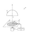
本発明が利点を提供する様式は、図1を参照することでより容易に理解することができ、図1は、本発明による画像センサ10の概略図である。画像センサ10は、画素化された画像アレイ13上に画像を形成する魚眼レンズ12を備える。アレイ13は、CCDアレイまたはCMOSフォトダイオードアレイといった任意のタイプの画像センサから構築されてもよい。画像センサ10はまた、レンズ12の光軸15を中心に画像アレイ13を回転させるアクチュエータ14を備える。
The manner in which the present invention provides advantages can be more easily understood with reference to FIG. 1, which is a schematic illustration of an
コントローラ17が、画像アレイ13の動きを制御する。実際には、画像アレイ13を用いてレンズ12からの画像を記録し、この画像がコントローラ17内に読み出される。次に軸15を中心に画像アレイを小さな角度だけ回転させ、別の画像を記録する。このプロセスは、コントローラ17が個々の画像よりも解像度が高い新たな画像を計算することを可能にするのに十分な画像が記録されるまで何回か繰り返す。あるいは、画像アレイは回転し続け、画像を取得し続けて、超解像画像の画質を高め続けてもよい。
A
以下の説明を簡単にするために、z軸をレンズ12の光軸としてデカルト座標系を定義する。画像アレイ13はこの座標系のxy平面にある。画像アレイの各ピクセルは、原点からの距離Rおよびx軸に対する角度θを指定することによって指定されてもよい。
In order to simplify the following description, a Cartesian coordinate system is defined with the z axis as the optical axis of the
画像平面の各ピクセルは、レンズ軸からピクセルまでの距離に応じた立体角からレンズ12に入ってくる光を測定する。例えば、ピクセル24は、21として示す立体角からの光を集め、ピクセル23は、22として示す立体角で入ってくる光を集める。各ピクセルに対応する立体角のサイズは、レンズ12の軸から当該ピクセルまでの距離Rのみに依存する。したがって、レンズ軸を中心に画像アレイが回転されても、各ピクセルの集光立体角のサイズは変わらない。これは、各回転角度で記録された様々な低解像度画像から解像度を高めた画像を計算するために必要な複雑さをかなり簡略化する。
Each pixel in the image plane measures light entering the
画像アレイが各回転角度Aで記録した画像はP(ri,ti,A)で表されることができ、ここで、(ri,ti)は、画像アレイのi番目のピクセルのxy平面における極座標である。超解像アルゴリズムの目的は、あたかも撮像要素の密度がより高い画像センサによって記録されたかのような画像を算出することである。例えば、アレイ13の各ピクセルが4つのサブピクセルに分けられるとすると、アルゴリズムは、いくつかの画像を合成して、あたかも高精細なピクセルアレイによって記録されたかのような、ある1つの角度におけるピクセル値
Image image array is recorded at each rotation angle A may be represented by P (r i, t i, A), where, (r i, t i) is the image array of i-th pixel Polar coordinates in the xy plane. The purpose of the super-resolution algorithm is to calculate an image as if it were recorded by an image sensor with a higher density of imaging elements. For example, if each pixel of

を生成する。通常、高解像度画像を得るには少なくとも4つの画像を合成しなければならない。ここで、 Is generated. Usually, at least four images must be combined to obtain a high resolution image. here,
は高精細な格子におけるj番目の点のxy平面の極座標である。 Is the polar coordinates of the xy plane of the jth point in the high definition grid.
任意の角度Akに対して、測定されたピクセル値P(ri,ti,Ak)はそれぞれ、高精細なピクセルアレイのいくつかのピクセル値の加重和として書き表すことができる。低解像度ピクセルと高解像度ピクセルの関係は次の形で書き表すことができる。 For any angle A k , the measured pixel values P (r i , t i , A k ) can each be written as a weighted sum of several pixel values of a high definition pixel array. The relationship between low resolution pixels and high resolution pixels can be written in the following form.
ここで、hkはk番目の回転角度のインパルス応答である。レンズが回転対称である場合、式(1)は以下のように書き換えることができることを示すことができる。 Here, h k is an impulse response of the k-th rotation angle. If the lens is rotationally symmetric, equation (1) can be shown to be rewritten as follows:
Hは、全ての回転角度に対して同じであることに留意すべきである。すなわち、Hは、半径方向でのみ変わり、角度方向では不変である。 Note that H is the same for all rotation angles. That is, H changes only in the radial direction and does not change in the angular direction.
センサを回転させる代わりにセンサをx方向およびy方向に直線移動させることによって様々な低解像度画像を取得した場合を考える。各低解像度画像は、センサ位置(dxk,dyl)において撮影される。この場合、対応する低解像度画像と高解像度画像の関係は以下のような形となる。 Consider a case where various low-resolution images are acquired by linearly moving the sensor in the x and y directions instead of rotating the sensor. Each low resolution image is taken at the sensor position (dx k , dy l ). In this case, the relationship between the corresponding low-resolution image and high-resolution image is as follows.
つまり、各変位(dxk,dyl)は異なるインパルス応答を必要とする。式(3)で表される連立方程式を解くために必要となる計算資源は、式(2)で表される連立方程式を解くために必要となる計算資源よりも相当に多い。 That is, each displacement (dx k , dy l ) requires a different impulse response. The computational resources required to solve the simultaneous equations represented by Expression (3) are considerably larger than the computational resources required to solve the simultaneous equations represented by Expression (2).
式(2)によって定義される一次方程式の組は原則として、Pが十分な数の角度において測定されるという前提のもとで、fの値について解くことができる。このような系を解くための数学的アルゴリズムは当該技術分野において既知である。例えば、凸集合への投影法を使用して、結果として生じる連立方程式を解いてもよい。このようなアルゴリズムの詳細な議論について、読者はM. Tekalp著「Digital Video Processing」(Prentice Hall, 1995, ISBN 0-13-190075-7)を参照されたい。 The set of linear equations defined by equation (2) can in principle be solved for the value of f, assuming that P is measured at a sufficient number of angles. Mathematical algorithms for solving such systems are known in the art. For example, a projection onto a convex set may be used to solve the resulting simultaneous equations. For a detailed discussion of such algorithms, the reader is referred to “Digital Video Processing” by M. Tekalp (Prentice Hall, 1995, ISBN 0-13-190075-7).
実際には、方程式の組のサイズはかなり大きい。例えば、高精細なアレイが1000×1000個のピクセルを有する場合、解かなければならない方程式の組は100万個の方程式を含み、対応する行列は1012個のエントリを有する。幸いなことに、エントリのほとんどはゼロである。しかし、各方程式の重み付け関数間に何らかの関係がなければ、非ゼロエントリを記憶する問題でさえ重大となる可能性がある。レンズの対称軸を中心にセンサのアレイを回転させることによって各画像が取得されるという事実により、本発明において必要な簡略化が行われる。上記のように、このような簡略化は、画像同士が画像アレイの直線移動によって関係付けられる場合には不可能である。 In practice, the size of the equation set is quite large. For example, if a high-definition array has 1000 × 1000 pixels, the set of equations that must be solved includes 1 million equations and the corresponding matrix has 10 12 entries. Fortunately, most of the entries are zero. However, even if there is no relationship between the weighting functions of each equation, even the problem of storing non-zero entries can be significant. The fact that each image is acquired by rotating an array of sensors about the axis of symmetry of the lens provides the necessary simplification in the present invention. As mentioned above, such simplification is not possible when images are related by linear movement of the image array.
計算の複雑さを低減することに加えて、本発明の方法はまた、画像アレイのエッジ(周辺部)に近い画像部分によって導入される問題を減らす。従来技術のシステムでは、複数の低解像度画像が、画像アレイをx方向またはy方向に短い距離だけ平行移動させることによって形成される。つまり、様々な整数値のnおよびmの何らかの格子(ndx,mdy)上の位置を中心としたアレイの画像が撮影される。画像アレイは固定サイズであるため、低解像度画像は異なる視野を有する。すなわち、各画像はより大きなシーンの一部である。各画像は、他の画像によって共有されるn=m=0に対応する中心領域を有するが、画像のエッジは、より大きなシーンの、他のどの低解像度画像にも見えない部分のデータを含む場合がある。したがって、エッジピクセルの情報は少ないため、エッジにおいて行うことができる画像の改善は中心領域においてもたらされる改善よりも少ない。魚眼レンズの場合、改良が必要なのは外側のピクセルであり、中心ピクセルではない。よって、従来技術の方法で得られる結果は理想的とは言えない。さらに、エッジピクセルのいくつかは、全体シーンの、他のどのピクセルにも見えない部分を捉えるため、より大きなシーンの画像境界付近の内容に依存する高解像度画像の外側領域にアーティファクトが生じる可能性がある。 In addition to reducing computational complexity, the method of the present invention also reduces the problems introduced by image portions close to the edges (periphery) of the image array. In prior art systems, multiple low resolution images are formed by translating the image array by a short distance in the x or y direction. That is, an image of the array is taken centering on a position on some lattice (ndx, mdy) of various integer values n and m. Since the image array is a fixed size, the low resolution image has a different field of view. That is, each image is part of a larger scene. Each image has a central area corresponding to n = m = 0 shared by the other images, but the edges of the image contain data of the portion of the larger scene that is not visible to any other low resolution image There is a case. Thus, because there is less edge pixel information, the image improvements that can be made at the edges are less than those brought about in the central region. In the case of a fisheye lens, it is the outer pixel that needs improvement, not the center pixel. Thus, the results obtained with the prior art methods are not ideal. In addition, some of the edge pixels capture parts of the entire scene that are not visible to any other pixel, which can lead to artifacts in the outer area of the high-resolution image that depend on the content near the image boundary of the larger scene. There is.
本発明の上述の実施形態は、結像レンズが魚眼レンズであると仮定している。魚眼レンズの場合、サンプリングレートが最も低い領域は、視野の周辺領域である。これはちょうど本発明において、高解像度画像の、低解像度画像に対して解像度が最も改善される領域である。本発明は具体的には、その領域においてさらなるサンプルを提供し、これらのサンプルは(回転角度により)等間隔で離間している。したがって、本発明は、適度に離間したサンプルを、ちょうどそれらが最も必要とされる領域において提供するという点で魚眼レンズに良く適している。しかし、本発明の利点は、各ピクセルによってサンプリングされる立体角がレンズの光軸からピクセルまでの距離のみに依存する任意のレンズ、すなわち回転対称のレンズを用いても実現することができる。 The above-described embodiments of the present invention assume that the imaging lens is a fisheye lens. In the case of a fisheye lens, the region where the sampling rate is the lowest is the peripheral region of the visual field. This is just the region in the present invention where the resolution is most improved over the low resolution image of the high resolution image. The present invention specifically provides further samples in that region, these samples being equally spaced (by rotation angle). Thus, the present invention is well suited for fisheye lenses in that they provide reasonably spaced samples just in the areas where they are most needed. However, the advantages of the present invention can also be realized using any lens, ie a rotationally symmetric lens, in which the solid angle sampled by each pixel depends only on the distance from the optical axis of the lens to the pixel.
本発明によって行われる計算の簡略化は回転対称のレンズに依存するが、本発明は、そのようなレンズを有しないシステムにおいて利点を提供することができる。センサを連続的に回転させるために必要な機械機構は一般に、センサを水平方向と垂直方向の両方において往復移動させるために必要な機械機構よりも遥かに単純である。さらに、センサの回転は、センサの直線的な往復移動よりも遥かに高速で行うことができる。したがって、本発明による画像記録システムは、非回転対称のレンズでも利点を提供することができる。 Although the computational simplification performed by the present invention relies on rotationally symmetric lenses, the present invention can provide advantages in systems that do not have such lenses. The mechanical mechanism required to continuously rotate the sensor is generally much simpler than the mechanical mechanism required to reciprocate the sensor in both the horizontal and vertical directions. Furthermore, the rotation of the sensor can be performed at a much higher speed than the linear reciprocation of the sensor. Therefore, the image recording system according to the present invention can provide advantages even with a non-rotationally symmetric lens.
上述の超解像アルゴリズムは、低解像度画像のそれぞれにおいて取り込まれるシーンが同じであるとみなしている。シーンが時間経過とともに変化する場合、個々の画像は、各画像に生じる動きまたは新たな像を補償されなければならない。シーン中の動きまたは新たな像を補償する超解像アルゴリズムは当該技術分野において既知であるため、ここでは詳述しない。 The super-resolution algorithm described above assumes that the scenes captured in each of the low resolution images are the same. If the scene changes over time, the individual images must be compensated for the motion or new images that occur in each image. Super-resolution algorithms that compensate for motion or new images in the scene are known in the art and will not be described in detail here.
センサの回転は断続したステップで行うことができ、あるいは、センサが回転しすぎてしまう前に画像アレイが画像を取り込むのに十分な速さを持つ場合、センサは連続的に回転されることができる。1000〜10,000フレーム/秒のフレームレートで画像を取り込むことができるCMOS画像センサが実証されている。したがって本発明は、そのようなセンサを用い、10〜100枚の低解像度画像を取り込み処理して、従来の30〜60フレーム/秒のフレームレートでリアルタイムに出力される各超解像画像を提供することによって高解像度ビデオを提供するために用いることができる。これらの高速センサは、空間解像度が限定されているかまたは信号対雑音比が低い場合が多いことに留意すべきである。よって本発明は、これらのセンサの長所を利用しながら、それらの弱点を矯正する手段を提供する。 The rotation of the sensor can be done in intermittent steps, or the sensor can be rotated continuously if the image array is fast enough to capture an image before the sensor has rotated too much. it can. CMOS image sensors that can capture images at a frame rate of 1000 to 10,000 frames / second have been demonstrated. Therefore, the present invention provides each super-resolution image output in real time at a conventional frame rate of 30 to 60 frames / second by using 10 to 100 low-resolution images and processing them using such a sensor. Can be used to provide high resolution video. It should be noted that these high speed sensors often have limited spatial resolution or a low signal to noise ratio. The present invention thus provides a means of correcting their weaknesses while taking advantage of the advantages of these sensors.
高解像度のビデオ出力を提供する本発明の実施形態も実施することができる。センサが1方向に回転し、回転角度の所定数の組それぞれごとに1つの低解像度フレームを取得する実施形態を考慮する。新たな低解像度画像がそれぞれ、所定数の以前に取得した画像と合成されて、ビデオストリームの高解像度フレームとして出力される新たな高解像度画像を提供する。 Embodiments of the invention that provide high resolution video output can also be implemented. Consider an embodiment in which the sensor rotates in one direction and acquires one low resolution frame for each of a predetermined number of sets of rotation angles. Each new low resolution image is combined with a predetermined number of previously acquired images to provide a new high resolution image that is output as a high resolution frame of the video stream.
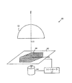
本発明の、上記の実施形態は、正方形または長方形の、センサのアレイを使用する。しかし、他の形状の、センサのアレイを使用することもできる。必要なのは画像アレイの中心部分のみであるため、残りの領域は、他の回路部に使用するか、製造歩留まりを改善するために空けておくことができる。例えば図2に示すように、円形の、センサのアレイを有利に使用することもできる。画像センサ50は、形状が円形である撮像アレイ54を使用する。このアレイは、より大きな任意形状のチップ53の一部であってもよい。アレイ54の外側の領域55は他の回路部のために使用してもよい。アレイ54がチップ53上で占める空間が少なくなるため、チップ歩留まりが、よってチップコストが低減される。
The above embodiments of the present invention use an array of sensors, square or rectangular. However, other shaped sensor arrays can be used. Since only the central portion of the image array is needed, the remaining area can be used for other circuit portions or left open to improve manufacturing yield. For example, as shown in FIG. 2, a circular, array of sensors may be advantageously used. The
同様に、図3に示すように六角形の画像アレイ64を使用することもできる。この場合も、チップ63の外側の空き領域を画像処理回路部のために使用するか、またはデバイスの歩留まりを改善するために空けておくことができる。
Similarly, a
代替的に、チップの形状は、いくつかの利点を得るために画像アレイの形状(例えば円形または六角形)に合わせてもよい。例えば、この形態のチップ形状により、チップまたは画像アレイの回転を単純化することができる。また、六角形または円形のようなチップ形状により、ウエハ上にチップをより高密度で密集させることができるため、ウエハ毎に作製されるセンサの数を増加させることができる。 Alternatively, the shape of the chip may be matched to the shape of the image array (eg, circular or hexagonal) to obtain several advantages. For example, this form of chip shape can simplify the rotation of the chip or image array. Further, the chip shape such as a hexagon or a circle allows the chips to be densely packed on the wafer, so that the number of sensors produced for each wafer can be increased.
上述の実施形態は、各画像センサが、正方形であると仮定した画像センサのアレイを使用する。しかし、他の形状の画像センサも使用することができる。例えば、図4の71に示すような、2つの同心円の内部のセグメントに一致する形状の画像センサを使用することもできる。一般に、回転中心から所与の半径にある個々のセンサの形状および面積は通常すべて同じであるが、異なる半径にある個々のセンサの形状および面積は異なる場合がある。 The above-described embodiments use an array of image sensors that assume that each image sensor is square. However, other shapes of image sensors can be used. For example, an image sensor having a shape corresponding to an inner segment of two concentric circles as shown in 71 of FIG. 4 may be used. In general, the shape and area of individual sensors at a given radius from the center of rotation are usually all the same, but the shape and area of individual sensors at different radii may be different.
当業者には、本発明に対する様々な修正が上記の説明および添付図面から明らかとなるであろう。したがって本発明は、添付の特許請求の範囲によってのみ限定されるものとする。 Various modifications to the present invention will become apparent to those skilled in the art from the foregoing description and accompanying drawings. Accordingly, the invention is intended to be limited only by the scope of the appended claims.
Claims (10)
シーンを前記画像センサのアレイ上に結像して、前記画像センサのそれぞれが前記シーンの異なる部分から光を受けるようにするレンズと、
前記レンズの光軸を中心に前記画像センサのアレイを回転させるアクチュエータと、
前記レンズの光軸回りの、複数の回転角度位置のそれぞれにおいて前記画像センサのアレイを読み出して、複数の比較的低解像度の画像を出力し、前記複数の前記比較的低解像度の画像を合成することによって前記シーンの画像を生成するコントローラと
を備えることを特徴とする装置。An array of image sensors;
A lens that images a scene onto the array of image sensors, each of the image sensors receiving light from a different part of the scene;
An actuator for rotating the array of image sensors about the optical axis of the lens;
Read the array of image sensors at each of a plurality of rotational angle positions about the optical axis of the lens, output a plurality of relatively low resolution images, and synthesize the plurality of relatively low resolution images. And a controller for generating an image of the scene .
画像センサのアレイを設けることと、 Providing an array of image sensors;
光軸を有するレンズを用いて前記シーンから複数の比較的低解像度の画像を形成することであって、前記複数の比較的低解像度の画像は、前記光軸を中心とする前記画像センサのアレイの異なる回転角度位置にそれぞれ対応するものである、形成することと、 Forming a plurality of relatively low resolution images from the scene using a lens having an optical axis, wherein the plurality of relatively low resolution images are centered on the optical axis; Each corresponding to a different rotational angle position of
前記比較的低解像度の画像を合成することであって、それによって、前記高解像度画像を形成する、合成することと Synthesizing the relatively low resolution image, thereby forming the high resolution image; and
を含むことを特徴とする、シーンの高解像度画像を生成する方法。A method for generating a high-resolution image of a scene, comprising:
Applications Claiming Priority (2)
| Application Number | Priority Date | Filing Date | Title |
|---|---|---|---|
| US10/173,330 US6642497B1 (en) | 2002-06-14 | 2002-06-14 | System for improving image resolution via sensor rotation |
| PCT/US2003/017938 WO2003107652A2 (en) | 2002-06-14 | 2003-06-05 | A system for improving image resolution via sensor rotation |
Publications (3)
| Publication Number | Publication Date |
|---|---|
| JP2005530410A JP2005530410A (en) | 2005-10-06 |
| JP2005530410A5 JP2005530410A5 (en) | 2006-07-13 |
| JP4369867B2 true JP4369867B2 (en) | 2009-11-25 |
Family
ID=29270017
Family Applications (1)
| Application Number | Title | Priority Date | Filing Date |
|---|---|---|---|
| JP2004514328A Expired - Fee Related JP4369867B2 (en) | 2002-06-14 | 2003-06-05 | A system to increase image resolution by rotating the sensor |
Country Status (4)
| Country | Link |
|---|---|
| US (1) | US6642497B1 (en) |
| JP (1) | JP4369867B2 (en) |
| AU (1) | AU2003240577A1 (en) |
| WO (1) | WO2003107652A2 (en) |
Families Citing this family (14)
| Publication number | Priority date | Publication date | Assignee | Title |
|---|---|---|---|---|
| US7389002B1 (en) | 2004-03-22 | 2008-06-17 | Knight Andrew F | Method for increasing resolution in a camera |
| US7602997B2 (en) * | 2005-01-19 | 2009-10-13 | The United States Of America As Represented By The Secretary Of The Army | Method of super-resolving images |
| US8666196B2 (en) * | 2005-01-19 | 2014-03-04 | The United States Of America As Represented By The Secretary Of The Army | System and method for super-resolution imaging from a sequence of color filter array (CFA) low-resolution images |
| US8577184B2 (en) * | 2005-01-19 | 2013-11-05 | The United States Of America As Represented By The Secretary Of The Army | System and method for super-resolution imaging from a sequence of color filter array (CFA) low-resolution images |
| US7856154B2 (en) * | 2005-01-19 | 2010-12-21 | The United States Of America As Represented By The Secretary Of The Army | System and method of super-resolution imaging from a sequence of translated and rotated low-resolution images |
| FR2927448B1 (en) * | 2008-02-12 | 2011-03-04 | Sagem Defense Securite | CORRECTION OF CAPTURED AND STABILIZED IMAGES |
| US9843742B2 (en) * | 2009-03-02 | 2017-12-12 | Flir Systems, Inc. | Thermal image frame capture using de-aligned sensor array |
| EP2485474B1 (en) * | 2011-02-08 | 2013-05-01 | Axis AB | Digital camera with adjustable sensor |
| US9071721B1 (en) | 2012-12-21 | 2015-06-30 | Google Inc. | Camera architecture having a repositionable color filter array |
| FR3000859B1 (en) * | 2013-01-09 | 2015-01-09 | Sagem Defense Securite | METHOD FOR MOVING A DIGITAL IMAGE SENSOR TO CALIBRATE IT |
| JP5881777B2 (en) * | 2014-06-24 | 2016-03-09 | オリンパス株式会社 | microscope |
| US20190162885A1 (en) * | 2017-11-30 | 2019-05-30 | Qualcomm Incorporated | Optical bandpass filter design |
| US10638061B2 (en) * | 2018-09-18 | 2020-04-28 | Analog Devices Global Unlimited Company | Active-pixel image sensor |
| RU2724151C1 (en) * | 2019-12-23 | 2020-06-22 | Олег Вадимович Смынтына | Method of increasing resolution of images obtained using matrix photodetectors |
Family Cites Families (6)
| Publication number | Priority date | Publication date | Assignee | Title |
|---|---|---|---|---|
| JPS6261480A (en) * | 1985-09-12 | 1987-03-18 | Fujitsu Ltd | Image pickup device |
| NL8901156A (en) * | 1989-05-08 | 1990-12-03 | Imec Inter Uni Micro Electr | RADIATION-SENSITIVE ORGAN OR SENSOR IN RETINA-LIKE CONFIGURATION. |
| US5990941A (en) * | 1991-05-13 | 1999-11-23 | Interactive Pictures Corporation | Method and apparatus for the interactive display of any portion of a spherical image |
| US5182652A (en) * | 1991-09-06 | 1993-01-26 | Eastman Kodak Company | High resolution thermal printing by imaging a hard copy image in vertical and horizontal increments smaller than the pixel pitch of a video imager array |
| JPH06350931A (en) * | 1993-06-02 | 1994-12-22 | Hamamatsu Photonics Kk | Solid-state image pickup device |
| US6005682A (en) * | 1995-06-07 | 1999-12-21 | Xerox Corporation | Resolution enhancement by multiple scanning with a low-resolution, two-dimensional sensor array |
-
2002
- 2002-06-14 US US10/173,330 patent/US6642497B1/en not_active Expired - Fee Related
-
2003
- 2003-06-05 JP JP2004514328A patent/JP4369867B2/en not_active Expired - Fee Related
- 2003-06-05 AU AU2003240577A patent/AU2003240577A1/en not_active Abandoned
- 2003-06-05 WO PCT/US2003/017938 patent/WO2003107652A2/en active Application Filing
Also Published As
| Publication number | Publication date |
|---|---|
| WO2003107652A3 (en) | 2004-06-03 |
| JP2005530410A (en) | 2005-10-06 |
| AU2003240577A1 (en) | 2003-12-31 |
| WO2003107652A2 (en) | 2003-12-24 |
| AU2003240577A8 (en) | 2003-12-31 |
| US6642497B1 (en) | 2003-11-04 |
Similar Documents
| Publication | Publication Date | Title |
|---|---|---|
| JP4418029B2 (en) | Image processing apparatus and camera system | |
| JP4369867B2 (en) | A system to increase image resolution by rotating the sensor | |
| JP4981124B2 (en) | Improved plenoptic camera | |
| JP3103008B2 (en) | System and method for electronic imaging and processing of a hemispherical field of view | |
| US20170371142A1 (en) | Circular Scanning Technique For Large Area Inspection | |
| US20110069148A1 (en) | Systems and methods for correcting images in a multi-sensor system | |
| CN109413407B (en) | High spatial resolution light field acquisition device and image generation method | |
| US20060078215A1 (en) | Image processing based on direction of gravity | |
| US20120099005A1 (en) | Methods and systems for reading an image sensor based on a trajectory | |
| WO2010051147A2 (en) | Method and apparatus for transforming a non-linear lens-distorted image | |
| JP2004536351A (en) | A method for capturing a panoramic image using a rectangular image sensor | |
| JPH0364908B2 (en) | ||
| KR101689534B1 (en) | Multiscale Imaging System | |
| CN111182191A (en) | Wide-field high-resolution camera shooting equipment and method based on aberration compensation calculation | |
| JP2020060763A (en) | Image sensor and image sensing method | |
| EP3564917B1 (en) | A method for detecting motion in a video sequence | |
| CN115086550B (en) | Meta imaging system | |
| US8289395B2 (en) | Enhancing image resolution by rotation of image plane | |
| CN113759543A (en) | Method for realizing flexible foveal imaging based on rotating biprism imaging system | |
| JP3805631B2 (en) | Multifocal omnidirectional imaging device | |
| JP3888847B2 (en) | Wide-field imaging device | |
| JPH08305841A (en) | Distorted image correcting display device | |
| KR101957353B1 (en) | Multiscale Imaging system with mirror rotation | |
| JP2004215228A (en) | Photographing device | |
| KR101721698B1 (en) | Multiscale Imaging System |
Legal Events
| Date | Code | Title | Description |
|---|---|---|---|
| A521 | Request for written amendment filed |
Free format text: JAPANESE INTERMEDIATE CODE: A523 Effective date: 20060524 |
|
| A621 | Written request for application examination |
Free format text: JAPANESE INTERMEDIATE CODE: A621 Effective date: 20060524 |
|
| A977 | Report on retrieval |
Free format text: JAPANESE INTERMEDIATE CODE: A971007 Effective date: 20080905 |
|
| A131 | Notification of reasons for refusal |
Free format text: JAPANESE INTERMEDIATE CODE: A131 Effective date: 20080916 |
|
| A601 | Written request for extension of time |
Free format text: JAPANESE INTERMEDIATE CODE: A601 Effective date: 20081216 |
|
| A602 | Written permission of extension of time |
Free format text: JAPANESE INTERMEDIATE CODE: A602 Effective date: 20081224 |
|
| A521 | Request for written amendment filed |
Free format text: JAPANESE INTERMEDIATE CODE: A523 Effective date: 20090313 |
|
| TRDD | Decision of grant or rejection written | ||
| A01 | Written decision to grant a patent or to grant a registration (utility model) |
Free format text: JAPANESE INTERMEDIATE CODE: A01 Effective date: 20090818 |
|
| A01 | Written decision to grant a patent or to grant a registration (utility model) |
Free format text: JAPANESE INTERMEDIATE CODE: A01 |
|
| A61 | First payment of annual fees (during grant procedure) |
Free format text: JAPANESE INTERMEDIATE CODE: A61 Effective date: 20090828 |
|
| R150 | Certificate of patent or registration of utility model |
Free format text: JAPANESE INTERMEDIATE CODE: R150 |
|
| FPAY | Renewal fee payment (event date is renewal date of database) |
Free format text: PAYMENT UNTIL: 20120904 Year of fee payment: 3 |
|
| FPAY | Renewal fee payment (event date is renewal date of database) |
Free format text: PAYMENT UNTIL: 20130904 Year of fee payment: 4 |
|
| R250 | Receipt of annual fees |
Free format text: JAPANESE INTERMEDIATE CODE: R250 |
|
| LAPS | Cancellation because of no payment of annual fees |