JP4367956B2 - Automatic mahjong table - Google Patents

Automatic mahjong table Download PDF

Info

Publication number
JP4367956B2
JP4367956B2 JP2006205597A JP2006205597A JP4367956B2 JP 4367956 B2 JP4367956 B2 JP 4367956B2 JP 2006205597 A JP2006205597 A JP 2006205597A JP 2006205597 A JP2006205597 A JP 2006205597A JP 4367956 B2 JP4367956 B2 JP 4367956B2
Authority
JP
Japan
Prior art keywords
rotating body
cylindrical rotating
standby
kite
stage
Prior art date
Legal status (The legal status is an assumption and is not a legal conclusion. Google has not performed a legal analysis and makes no representation as to the accuracy of the status listed.)
Expired - Fee Related
Application number
JP2006205597A
Other languages
Japanese (ja)
Other versions
JP2006314830A5 (en
JP2006314830A (en
Inventor
貞男 渡辺
収 高橋
英樹 小松原
智久 野々山
Original Assignee
電元オートメーション株式会社
貞男 渡辺
Priority date (The priority date is an assumption and is not a legal conclusion. Google has not performed a legal analysis and makes no representation as to the accuracy of the date listed.)
Filing date
Publication date
Family has litigation
First worldwide family litigation filed litigation Critical https://patents.darts-ip.com/?family=37535966&utm_source=google_patent&utm_medium=platform_link&utm_campaign=public_patent_search&patent=JP4367956(B2) "Global patent litigation dataset” by Darts-ip is licensed under a Creative Commons Attribution 4.0 International License.
Application filed by 電元オートメーション株式会社, 貞男 渡辺 filed Critical 電元オートメーション株式会社
Priority to JP2006205597A priority Critical patent/JP4367956B2/en
Publication of JP2006314830A publication Critical patent/JP2006314830A/en
Publication of JP2006314830A5 publication Critical patent/JP2006314830A5/ja
Application granted granted Critical
Publication of JP4367956B2 publication Critical patent/JP4367956B2/en
Anticipated expiration legal-status Critical
Expired - Fee Related legal-status Critical Current

Links

Images

Description

本発明は、卓内に投入された1組の牌を攪拌処理した後、自動的に整列牌を天板上に押し上げることのできる自動麻雀卓に関するものである。   The present invention relates to an automatic mahjong table that can automatically push up an alignment kite on a top board after stirring a set of kites thrown into the table.

自動麻雀卓は、種々の技術開発がなされているが、牌を攪拌して整列する洗牌技術としては、大凡、(1)傾斜ターンテーブルとホッパリングを用いて1つの取出口から牌を取出す方式、(2)水平ターンテーブルを用いて4つの取出口から牌を取出す方式に大別することができるが、(1)の公知例としては特許文献1(特開昭54-40741号公報)が、(2)の公知例としては特許文献2(特開昭61-244384号公報)が知られている。   Various technologies have been developed for the automatic mahjong table, but as a washing technique that stirs and aligns the straw, roughly, (1) take out the straw from one outlet using an inclined turntable and hopper ring. The system can be roughly divided into (2) a method of taking out the basket from four outlets using a horizontal turntable, and as a known example of (1), Patent Document 1 (Japanese Patent Laid-Open No. 54-40741) However, as a known example of (2), Patent Document 2 (Japanese Patent Laid-Open No. 61-244384) is known.

現在、ゲーム終了後の牌を麻雀卓の内部に投下して、攪拌しつつ牌を取り上げ、各場に均等数の2段積み牌を正方形状に配列形成して待機させ、次のプレイ開始にあたって、この正方形状に配列した2段積み牌を天板上に押し出すものが殆どであるが、このような、従来型の自動麻雀卓を用いた場合、ゲーム開始において、慣習的に、親が振ったサイコロの目によって、懸賞牌を反転させたり、城壁牌の一部を各プレーヤーが順にとって配牌を行っている。
このように従来型の自動麻雀卓においては、人手によって配牌を行うという作業が必要であるが、係る行為は、煩わしい上に、間違えたり、2段積み牌を崩してしまったりするという問題点を有している。
Currently, after the game is over, drop the puppet into the mahjong table, pick up the puppet while stirring, place an equal number of two-stage stacks in a square shape in each field, and wait for the next play. In most cases, the two-stage stacking tiles arranged in a square shape are pushed onto the top board, but when such a conventional automatic mahjong table is used, the parent swings conventionally at the start of the game. Depending on the dice, the players can flip the sweepstakes or distribute part of the ramparts in order by each player.
As described above, in the conventional automatic mahjong table, it is necessary to perform a manual arrangement, but such an operation is troublesome and can be mistaken or the two-stage stacking can be broken. have.

こうした問題に対処するため特許文献3及び特許文献4には、2段積み整列牌と共に配牌用の整列牌までを自動的に形成し、これらを天板上に押し出すことのできる自動麻雀卓が開示されている。しかし、これらの自動麻雀卓は、いずれも配牌、及び2段積み牌をそれぞれ専用に設けられた2つの別の昇降機構によって天板上に押し出すものであって、構造が複雑で大型化するという問題点を有している。   In order to cope with these problems, Patent Document 3 and Patent Document 4 include an automatic mahjong table that can automatically form a two-layered stacking rod and an alignment rod for serving, and push these onto the top plate. It is disclosed. However, each of these automatic mahjong tables pushes out a table and a two-stage stacking board onto the top board by two separate lifting mechanisms provided exclusively for each, and the structure is complicated and increases in size. Has the problem.

このことは、例えば、特許文献3に開示された自動麻雀卓の洗牌技術は、従来の特許文献1に開示された従来の自動麻雀卓と同様な技術が用いられており、攪拌装置内の牌のひとつの出口から取り出す場合、各場に牌を移送するための大きなコンベヤが必要となる。そのため、特許文献3に開示された自動麻雀卓では、同公報第1図に示されるように、各場において、2段積み牌用の昇降台と待機台と、配牌用昇降台と待機台と、更には搬送コンベアとの多くの装置が並ぶため複雑になり、麻雀卓が大型化になってしまうとういう虞があった。   This is because, for example, the automatic mahjong table washing technique disclosed in Patent Document 3 uses the same technology as the conventional automatic mahjong table disclosed in Patent Document 1, When taking out from one exit of the kite, a large conveyor is required to transport the kite to each place. Therefore, in the automatic mahjong table disclosed in Patent Document 3, as shown in FIG. 1 of the same publication, in each place, a lifting platform and a standby platform for a two-stage stack, a lifting platform and a standby platform for a serving In addition, since many devices are arranged along with the conveyor, it becomes complicated, and there is a risk that the mahjong table becomes large.

また、前掲の特許文献2に開示された自動麻雀卓の洗牌技術は、磁石を埋没した水平回転体を各場毎に設けて、攪拌装置内の牌を取り出すため大きなコンベヤは不要であるが、2段積み牌が水平回転体の吸着面より下に設けなければならないこと、及び、水平回転体が昇降台の下方にはみだすので昇降台を水平回転体以下には下げられず、このため、特許文献5に開示されているように、2段積み牌を天板上に押し出すとき、待機台上の2段積み牌を昇降台の降下位置まで持ち上げて昇降台に移載しなければならず、2段積み牌を天板上に押し出す機構が複雑で大型化してしまう。
更に、前掲の特許文献4に開示された技術は、同報第3図、及び、第5図に示されるように、磁石を埋没した水平回転体とその横に設けた小型搬送コンベヤによって牌を取り出しているが、水平回転体と搬送コンベヤ等の攪拌装置の周辺が複雑で場所をとり、やはり複雑で大型化してしまう。
特開昭54−40741号公報 特開昭61−244384号公報 特開昭62−49879号公報 特開昭62−68479号公報 特開昭61−244385号公報
In addition, the automatic mahjong table washing technique disclosed in the above-mentioned Patent Document 2 is provided with a horizontal rotating body in which a magnet is buried in each place, and a large conveyor is not required to take out the straw in the stirring device. The two-stage stack must be provided below the adsorption surface of the horizontal rotator, and the horizontal rotator protrudes below the elevator, so the elevator cannot be lowered below the horizontal rotator. As disclosed in Patent Document 5, when a two-stage stacking bar is pushed out on the top plate, the two-stage stacking box on the stand must be lifted to the lowered position of the lifting platform and transferred to the lifting platform. The mechanism for pushing out the two-stage stacker onto the top plate is complicated and large.
Further, the technique disclosed in the above-mentioned Patent Document 4 is a method of producing a bag by using a horizontal rotating body in which magnets are buried and a small conveying conveyor provided on the side thereof, as shown in FIGS. 3 and 5. Although it has been taken out, the surroundings of the horizontal rotating body and the agitator such as the conveyor are complicated and take up space.
JP 54-40741 A Japanese Patent Laid-Open No. 61-244384 JP 62-49879 A JP 62-68479 A JP-A 61-244385

本発明は、これらの問題点に鑑みてなされたもので、自動麻雀卓において、攪拌装置から牌を取り上げ、形成・供給機構に供給する機構を簡単にし、機構自体を小型にし、自動麻雀卓をコンパクトで経済的にすることを課題とするものである。   The present invention has been made in view of these problems. In an automatic mahjong table, the mechanism for picking up straw from a stirrer and supplying it to the forming / feeding mechanism is simplified, the mechanism itself is reduced in size, The challenge is to make it compact and economical.

上記課題を解決するための請求項1の発明は、各場へ牌を供給するためのつの開口が設けられている天板を有する本体と、磁性体を埋設した牌を攪拌するため前記本体内に設けられた攪拌装置と、前記各場の開口に対応してそれぞれ前記攪拌装置から牌を取り上げる汲上機構と、該汲上機構によって取り上げられた牌を一方向に整列して送り出すための整列機構と、該整列機構から牌を受け取り所定の整列牌を形成して待機させるための形成・待機機構と、該形成・待機機構で形成され待機している前記整列牌を対応する開口から天板上に上昇させる機構とを備えた自動麻雀卓であって、
前記攪拌装置は回転するターンテーブルと外壁とが設けられ、攪拌された牌は前記ターンテーブルの回転により外壁に向かって移動させ、前記牌を取り上げる汲上機構は円筒回転体が設けられ、該円筒回転体の周面部位には前記円筒回転体の一側端から牌の横幅ほどの幅をもつ吸着面を配設し、前記吸着面の中心には磁石を埋没し、前記吸着面に磁気力により牌を吸着して下方から上方に吸い上げるように円筒回転体を回転させ、前記整列機構は、前記円筒回転体に吸い上げられた牌の方向を揃えるため前記吸着面の外側の軌道に沿って配設した案内部材と、該案内部材の延長上であって前記円筒回転体の頂上付近には前記円筒回転体の吸着面から牌を剥離して前記形成・待機機構に導くための誘導路を設け、前記円筒回転体によって下方位置にて取り上げられた牌は、前記案内部材にそって牌の向きを揃えながら上方に移動するとともに前記誘導路の一端に捕捉されて前記円筒回転体から離脱するようにしたことを特徴とする。
請求項2の発明は、請求項1に記載の自動麻雀卓において、前記形成・待機機構は、前記誘導路に捕捉された牌の進行方向の延長上に該牌を載置するための載置部を設け、前記誘導路に捕捉された牌を受け取り前記載置部に移送するための移送手段と、前記載置部の一方の側に整列牌を形成して待機させるための待機台を含む待機機構と、前記載置部を挟み前記待機台の反対側から前記載置部に移送された牌を前記待機台上に押し出して前記待機台上に所定数の整列牌を形成するための押出機構とを含み、前記円筒回転体の駆動機構と、前記移送手段の駆動機構と、前記押出機構の駆動機構は同一の駆動源に連結されているとともに、前記円筒回転体と、前記移送手段と、前記押出機構は所定の位相関係で協働していることを特徴とする。
請求項3の発明は、請求項2に記載の自動麻雀卓において、前記待機機構には1段積の配牌ブロックが形成される第1の台(配牌台801)と2段積牌ブロックが形成される第2の台(待機台802)が設けられ、前記載置部には第1の台と第2の台に対応する載置台(下載置台702、上載置台703)が設けられ、前記整列機構から送り出される牌を、前記2つの載置台に選択的に送給するための選択送給手段とを備え、前記第1の台上に配牌ブロックとして形成・待機させると共に、前記第2の台上に二段積み牌ブロックとして形成・待機させるようにしたことを特徴とする。
請求項4の発明は、請求項1乃至3のいずれかに記載の自動麻雀卓において、前記汲上機構と前記形成・待機機構との間に牌反転機構650を備え、懸賞牌を形成できるようにしたことを特徴とする。
The invention of claim 1 for solving the above problems, the main body to agitate the body, the tiles were buried magnetic body having a top plate in which four openings for supplying tiles to each field is provided a stirring device provided within said a pumping mechanism to take up tiles from each said stirring device in response to the opening of the field, the alignment mechanism for delivering and aligning the tiles that are taken up by該汲on mechanism in one direction And a forming / standby mechanism for receiving a ridge from the alignment mechanism to form and wait for a predetermined alignment ridge, and the alignment ridge formed by the formation / standby mechanism waiting on the top plate An automatic mahjong table with a mechanism for raising
The stirring device is provided in the turntable and the outer wall of the rotating, is stirred tiles moved toward the outer wall by rotation of the turntable, pumping mechanism taking up the tiles cylindrical rotary member is provided, the cylindrical rotary A suction surface having a width about one side width of the flange from the one side end of the cylindrical rotating body is disposed on a peripheral surface portion of the body, a magnet is buried in the center of the suction surface, and a magnetic force is applied to the suction surface. The cylindrical rotating body is rotated so as to suck up and suck up the soot from below, and the alignment mechanism is arranged along a track outside the suction surface to align the direction of the soot sucked up by the cylindrical rotating body. A guide path for peeling the ridge from the suction surface of the cylindrical rotating body and guiding it to the forming / standby mechanism on the guide member and on the extension of the guide rotating member near the top of the cylindrical rotating body , Lower position by the cylindrical rotating body Tiles which are taken up at the is characterized in that while moving upward while aligning the orientation of the tiles along the guide member is caught on one end of the guideway and so detached from the cylindrical rotating body.
According to a second aspect of the present invention, in the automatic mahjong table according to the first aspect, the formation / standby mechanism is a placement for placing the spider on an extension of the travel direction of the spear captured in the guide path. A transfer means for receiving and transferring the trap captured in the guide path to the mounting portion described above, and a stand for forming an alignment rod on one side of the mounting portion and waiting and standby mechanism, for forming a predetermined number of aligned tiles tiles that are transported to the mounting section on the waiting stand extruded on the wait table from the opposite side of the stand base sandwiching said mounting portion A drive mechanism for the cylindrical rotating body, a drive mechanism for the transfer means, and a drive mechanism for the extrusion mechanism are connected to the same drive source, and the cylindrical rotary body and the transfer means. The extrusion mechanism cooperates with a predetermined phase relationship.
According to a third aspect of the present invention, in the automatic mahjong table according to the second aspect of the present invention, a first stand (layout stand 801) and a two-tier stacker block on which the standby mechanism is formed with the standby mechanism are provided. A second table (standby table 802) is provided, and the mounting unit is provided with mounting tables (a lower mounting table 702 and an upper mounting table 703) corresponding to the first table and the second table, Selective feeding means for selectively feeding the baskets fed from the alignment mechanism to the two mounting tables, and forming and waiting as a layout block on the first table; It is characterized in that it is formed and put on standby as a two-stage stacking block on two stands.
According to a fourth aspect of the present invention, in the automatic mahjong table according to any one of the first to third aspects, a reversing mechanism 650 is provided between the pumping mechanism and the formation / standby mechanism so that a prize can be formed. It is characterized by that.

請求項1の発明によれば、牌を取り上げる汲上機構を、円筒回転体と吸着面を設けて、吸着面の牌を磁気力により吸着して下方から上方に吸い上げるように円筒回転体を縦方向に回転させたので、スペース的には従来の水平方向に回転する汲上方式とは異なり円筒回転体の幅は牌の縦幅と略等しい寸法でよく、かつ、水平方向の移動は円筒回転体の幅があれば良いから、これらにより、攪拌装置から牌を取り上げる汲上機構を小型にすることができ、結果として、自動麻雀卓の全体が小型、軽量、コンパクトとなり経済的に有利となる。
また、請求項1の効果に加えて、請求項2の発明によれば、載置部に移送された牌を反対側から待機機構台上に押し出すので、無理なく整列牌を形成することができ、請求項3の発明によれば、予め配牌と2段積牌とを形成しておくことができ、請求項4の発明によれば、配牌の形成と同時に懸賞牌を配置することができる。
According to the first aspect of the present invention, the pumping mechanism for picking up the soot is provided with a cylindrical rotating body and an adsorption surface, and the cylindrical rotating body is vertically oriented so that the soot on the attraction surface is attracted by magnetic force and sucked upward from below. Unlike the conventional pumping system that rotates in the horizontal direction, the width of the cylindrical rotating body may be approximately the same as the vertical width of the ridge, and the horizontal movement is the same as that of the cylindrical rotating body. Since it is sufficient if there is a width, it is possible to reduce the size of the pumping mechanism for picking up the straw from the stirring device. As a result, the whole automatic mahjong table becomes small, light and compact, which is economically advantageous.
Further, in addition to the effect of the first aspect, according to the second aspect of the present invention, the hooks transferred to the mounting portion are pushed out from the opposite side onto the standby mechanism table, so that the alignment hooks can be formed without difficulty. According to the invention of claim 3, the arrangement and the two-stage loading basket can be formed in advance, and according to the invention of claim 4, the prize basket can be arranged simultaneously with the formation of the arrangement. it can.

以下、図面を参照して本発明の好適な自動麻雀卓の実施の形態の一例につき詳細に説明する。
図1は、本発明による自動麻雀卓の実施の形態の一例を概略的に示す斜視図である。自動麻雀卓1は、本体2がスタンド3によって支えられており、本体2に設けられた天板4の中央部には牌を落とし込むための牌投入口4Aが形成されている。牌投入口4Aは蓋5によって開閉できる構成となっており、蓋5は図示しない開閉機構によって開閉される。本体2の中央に設けられている操作板6のスタートスイッチ6Aを操作することにより開閉機構が作動して蓋5を下方に移動させ、牌を牌投入口4Aから下方に落とし込むことができるようになっている。
Hereinafter, an example of a preferred embodiment of an automatic mahjong table of the present invention will be described in detail with reference to the drawings.
FIG. 1 is a perspective view schematically showing an example of an embodiment of an automatic mahjong table according to the present invention. In the automatic mahjong table 1, a main body 2 is supported by a stand 3, and a cocoon insertion port 4 </ b> A for dropping a cocoon is formed in a central portion of a top plate 4 provided in the main body 2. The eaves inlet 4A can be opened and closed by a lid 5, and the lid 5 is opened and closed by an opening / closing mechanism (not shown). By operating the start switch 6A of the operation plate 6 provided in the center of the main body 2, the opening / closing mechanism is operated to move the lid 5 downward, so that the basket can be dropped downward from the basket input port 4A. It has become.

天板4上であって、牌投入口4Aと天板4の周縁との間には、配牌用の整列牌(以後、配牌ブロックと称する)BA及びプレー開始後にプレーヤが順番に取り込むための牌を2段積みとした2段積み整列牌(以後、2段積牌ブロックと称する)BBを本体2の内部から天板4の上面に供給するための細長い矩形の4つの牌出口(開口)7A、7B、7C、7Dが各プレーヤに対向するようにして形成されており、これらの牌出口7A、7B、7C、7Dは、後述するようにして各ブロックを供給するときだけ開く構成となっている。   On the top board 4 and between the bowl input slot 4A and the peripheral edge of the top board 4, a player arranges an arrangement basket (hereinafter referred to as a layout block) BA and a player in order after the game starts. Four long and narrow rectangular rod outlets (openings) for supplying a two-stage stacked rod (hereinafter referred to as a two-layered rod block) BB from the inside of the main body 2 to the upper surface of the top plate 4 ) 7A, 7B, 7C, 7D are formed so as to face each player, and these saddle outlets 7A, 7B, 7C, 7D are configured to open only when supplying each block as described later. It has become.

図2は、自動麻雀卓1において使用される牌10の構成を示す図である。牌10は合成樹脂の成形体として作られており、その内部に磁性体が埋設された構造となっている。本実施の形態においては、この磁性体として磁石11が用いられており、磁石11は牌10の中央部に埋設されている。なお、自動麻雀卓1においては牌は2組用いられ、その一方の組で競技し、他方の組の牌は自動麻雀卓1内で攪拌処理して、配牌ブロックと2段積牌ブロックの2種の整列牌に形成して待機させておく構成となっている。   FIG. 2 is a diagram showing a configuration of the cocoon 10 used in the automatic mahjong table 1. The cage 10 is made as a synthetic resin molded body, and has a structure in which a magnetic material is embedded. In the present embodiment, a magnet 11 is used as the magnetic body, and the magnet 11 is embedded in the central portion of the cage 10. In the automatic mahjong table 1, two sets of kites are used, and one set of the kites is used for competition. It has a configuration in which it is formed in two kinds of alignment rods and kept waiting.

図1では図示するのを省略しているが、自動麻雀卓1の本体2の下方には、配牌有/無選択スイッチ、懸賞牌有/無選択スイッチ及びゲーム選択スイッチが設けられており、これらのスイッチを適宜に操作して目的に適ったゲームを行うことができるようになっている。また、ゲーム選択スイッチにより、3人用3種類、4人用3種類の計6種類のゲームモードを選択でき、各ゲームモードに対応した配列パターンが適用される。   Although not shown in FIG. 1, an automatic mahjong table 1 has a distribution / non-selection switch, a prize selection / non-selection switch, and a game selection switch below the main body 2. By appropriately operating these switches, a game suitable for the purpose can be played. In addition, the game selection switch can select a total of six game modes: three for three players and three for four players, and an array pattern corresponding to each game mode is applied.

図3は、自動麻雀卓1の内部機構を説明するための、天板4を取り外した場合の自動麻雀卓1本体2内の概略平面図である。本体2内の中央部分には、落とし込まれた牌を攪拌するための攪拌機構100が設けられており、本体2の四隅部には、攪拌機構100によって攪拌された牌を汲み上げるための汲上機構200がそれぞれ設けられている。   FIG. 3 is a schematic plan view of the inside of the main body 2 of the automatic mahjong table 1 when the top plate 4 is removed for explaining the internal mechanism of the automatic mahjong table 1. A stirring mechanism 100 for stirring the dropped soot is provided in the central portion of the main body 2, and a pumping mechanism for pumping the soot stirred by the stirring mechanism 100 is provided at the four corners of the main body 2. 200 is provided.

攪拌機構100は、中央部に対して外側がやや低く形成されている円形状のターンテーブル101と、ターンテーブル101を囲むように形成された外壁102と、一端がそれぞれターンテーブル101中心付近に固定された2つの棒状弾性体103、103と、ターンテーブル101の下面側にその周縁に沿って等間隔に設けられた4つの牌反転用磁石104と、ターンテーブル駆動機構105とを備えて成っている。ターンテーブル101の下には歯車106が設けられており、ターンテーブル101は歯車106と同期して回転するように構成されている。   The stirring mechanism 100 has a circular turntable 101 whose outer side is formed slightly lower than the center, an outer wall 102 formed so as to surround the turntable 101, and one end fixed in the vicinity of the center of the turntable 101. Two rod-like elastic bodies 103, 103, four reversing magnets 104 provided at equal intervals along the periphery of the lower surface of the turntable 101, and a turntable driving mechanism 105. Yes. A gear 106 is provided under the turntable 101, and the turntable 101 is configured to rotate in synchronization with the gear 106.

歯車106は4つの汲上機構200の各駆動用歯車201とそれぞれ噛み合っている。ターンテーブル駆動機構105は4つの駆動用歯車201のうちの1つを回転駆動させるため、その駆動用歯車201と一体に運動するタイミングプーリ202とタイミングベルト203を介して連結されている駆動モータ204を備えている。したがって、駆動モータ204が駆動されるとその回転がタイミングベルト203を介してタイミングプーリ202に伝達され、駆動用歯車201がタイミングプーリ202と一体に回転し、駆動用歯車201と噛み合っている歯車106が回転し、これによりターンテーブル101が矢印方向に回転する。
そして、ターンテーブル101の回転により、他の3つの駆動用歯車201も同時に回転する。図22には、歯車106と駆動用歯車201との噛合状態が見えている。
The gears 106 mesh with the driving gears 201 of the four pumping mechanisms 200, respectively. The turntable drive mechanism 105 rotationally drives one of the four drive gears 201, and therefore, a drive motor 204 connected via a timing pulley 203 and a timing belt 203 that move integrally with the drive gear 201. It has. Therefore, when the drive motor 204 is driven, the rotation is transmitted to the timing pulley 202 via the timing belt 203, and the drive gear 201 rotates integrally with the timing pulley 202 and meshes with the drive gear 201. Is rotated, thereby turning the turntable 101 in the direction of the arrow.
As the turntable 101 rotates, the other three driving gears 201 rotate simultaneously. In FIG. 22, the meshing state of the gear 106 and the driving gear 201 can be seen.

図22を参照すると、駆動用歯車201の中心には孔が設けられており、駆動用歯車201は該孔内に支持軸205が挿通されて回転自在に保持されている。
駆動用歯車201の下方においてタイミングプーリ202が歯車201に固定されている。そして、支持軸205に固着されたトルクリミッタ206の上部に形成された凸部と駆動用歯車201の下方に形成された凹部とが係合するように構成されている。したがって歯車106の回転に伴い駆動用歯車201が回転すると、駆動用歯車201に係合しているトルクリミッタ206が回転しこれにより支持軸205が回転する。トルクリミッタ206は支持軸205に過大な負荷が生じた時の衝撃をやわらげる役目を果たす目的で備えられている。
Referring to FIG. 22, a hole is provided in the center of the driving gear 201, and the driving gear 201 is rotatably held by inserting a support shaft 205 into the hole.
A timing pulley 202 is fixed to the gear 201 below the driving gear 201. And the convex part formed in the upper part of the torque limiter 206 fixed to the support shaft 205 and the concave part formed under the driving gear 201 are engaged. Therefore, when the driving gear 201 rotates with the rotation of the gear 106, the torque limiter 206 engaged with the driving gear 201 rotates, and thereby the support shaft 205 rotates. The torque limiter 206 is provided for the purpose of reducing the impact when an excessive load is generated on the support shaft 205.

ターンテーブル101のやや上方には、適度な可撓性を持たせたコイルバネからなる棒状弾性体103、103が、各一端を中央部の保持体112に固定することによって放射状に配設されている。保持体112は回転せず静止したままであるから、ターンテーブル101が回転すると、牌投入口4A(図1参照)よりターンテーブル101上に落とし込まれて山積み状となった牌10は棒状弾性体103により押しやられ、牌10は棒状弾性体103の手前側に集められて攪拌されることになる。この場合、牌10はターンテーブル101の回転力により自ら棒状弾性体103を押して屈曲させながら徐々に外壁102側に向かって移動していく。   Slightly above the turntable 101, rod-like elastic bodies 103 and 103 made of coil springs having appropriate flexibility are arranged radially by fixing one end to a holding body 112 at the center. . Since the holding body 112 does not rotate and remains stationary, when the turntable 101 rotates, the basket 10 that has been dropped onto the turntable 101 from the basket input port 4A (see FIG. 1) and is piled up has a rod-like elasticity. The heel 10 is pushed by the body 103 and is collected on the near side of the rod-like elastic body 103 and stirred. In this case, the flange 10 gradually moves toward the outer wall 102 side while pushing and bending the rod-like elastic body 103 by the rotational force of the turntable 101.

図4及び図5を参照して、ターンテーブル101の外壁102側に移動した牌を汲み上げるための汲上機構200について説明する。   With reference to FIG.4 and FIG.5, the pumping mechanism 200 for pumping up the kite which moved to the outer wall 102 side of the turntable 101 is demonstrated.

汲上機構200は、前述の如く4つ設けられているが、4つの汲上機構200は、全く同様に構成されているため、ここでは、そのうちの1つの機構200について説明する。汲上機構200は、外壁102側に移動してきた牌10を取り上げるための機構であり、牌10を磁気力により吸着するための円筒回転体401と、円筒回転体駆動機構404とを備えて成っている。   Although the four pumping mechanisms 200 are provided as described above, since the four pumping mechanisms 200 are configured in exactly the same manner, only one of the mechanisms 200 will be described here. The pumping mechanism 200 is a mechanism for picking up the kite 10 that has moved to the outer wall 102 side, and includes a cylindrical rotating body 401 for attracting the kite 10 by magnetic force, and a cylindrical rotating body drive mechanism 404. Yes.

先ず、円筒回転体401について図6及び図7を参照して説明する。図6は円筒回転体401の立面図、図7は円筒回転体401の平面図である。円筒回転体401は牌10の縦幅と略等しい長さ(lL )の高さ寸法を有した円筒形状をした樹脂材からなり、一側端から牌の横幅分の長さ(ls )の位置には溝401Aが形成されている。円筒回転体401の周面部位には、2カ所等間隔に、平伏牌の面積ほど平に削り落とした吸着面401Bが形成されており、その中心部には吸着面401Bから僅かの埋設深さ距離をもって、磁石401Cが埋設されている。 First, the cylindrical rotating body 401 will be described with reference to FIGS. 6 and 7. FIG. 6 is an elevation view of the cylindrical rotating body 401, and FIG. 7 is a plan view of the cylindrical rotating body 401. The cylindrical rotating body 401 is made of a resin material having a cylindrical shape having a height dimension (l L ) that is substantially equal to the vertical width of the ridge 10, and has a length (ls) corresponding to the lateral width of the ridge from one side end. A groove 401A is formed at the position. The circumferential surface portion of the cylindrical rotating body 401 is formed with an adsorption surface 401B that is scraped flat as much as the area of the flat protuberance at equal intervals in two places, and the embedding depth from the adsorption surface 401B is a slight embedding depth. A magnet 401C is embedded with a distance.

円筒回転体401には、内端縁側にテーパ付けされた比較的幅の狭いフランジ部401Eが形成されており、フランジ部401Eは、吸着面401Bに対応する部分に後端に僅かに傾斜部401Dを残して前記吸着面401Bと同面になるような切欠401Fが形成されている。   The cylindrical rotating body 401 is formed with a relatively narrow flange portion 401E that is tapered toward the inner edge, and the flange portion 401E is slightly inclined at the rear end at a portion corresponding to the suction surface 401B. A notch 401F is formed so as to be flush with the suction surface 401B.

再び図4及び図5を参照すると、円筒回転体401の中心には回転軸405が嵌挿されていて、円筒回転体401はこの回転軸405に固定されており、この回転軸405は円筒回転体401を挟む案内部材501と反対側に設けた側壁を固定するベース(図示せず)とによって回転自在に支持されている。   4 and 5 again, a rotating shaft 405 is fitted in the center of the cylindrical rotating body 401, and the cylindrical rotating body 401 is fixed to the rotating shaft 405. The rotating shaft 405 is cylindrically rotated. It is rotatably supported by a guide member 501 sandwiching the body 401 and a base (not shown) for fixing a side wall provided on the opposite side.

円筒回転体401が固定されている回転軸405にはタイミングプーリ405Aが固定的に取り付けられている。また、駆動用歯車201の上方には別の回転軸406が設けられており、この回転軸406にはタイミングプーリ406Aが固定的に取り付けられている。回転軸405のタイミングプーリ405Aと回転軸406のタイミングプーリ406Aとはタイミングベルト407によって連結されており、回転軸406は支持軸205とカサ歯車408を介して連結されている。ここでは、駆動用歯車201が一回転すると円筒回転体401が一回転する構成となっている。円筒回転体401は、ターンテーブル101内を覗くように突出しており、且つ、円筒回転体401とターンテーブル101との隙間は牌10の厚さよりやや広い程度になっていて、この間を通過する平伏状の牌10を円筒回転体401に埋設した磁石401C(図6、図7参照)で吸着して牌を汲み上げることができるようになっている。   A timing pulley 405A is fixedly attached to a rotating shaft 405 to which the cylindrical rotating body 401 is fixed. Further, another rotating shaft 406 is provided above the driving gear 201, and a timing pulley 406A is fixedly attached to the rotating shaft 406. The timing pulley 405A of the rotating shaft 405 and the timing pulley 406A of the rotating shaft 406 are connected by a timing belt 407, and the rotating shaft 406 is connected via a support shaft 205 and a bevel gear 408. Here, when the driving gear 201 rotates once, the cylindrical rotating body 401 rotates once. The cylindrical rotating body 401 protrudes so as to look into the turntable 101, and the gap between the cylindrical rotating body 401 and the turntable 101 is slightly wider than the thickness of the flange 10, and the flattening that passes between these The rod 10 can be pumped up by being attracted by a magnet 401C (see FIGS. 6 and 7) embedded in a cylindrical rotating body 401.

円筒回転体401に埋設した磁石401Cの極性と、牌10に埋設した磁石11の極性との関係は、牌10が字面を上にした状態で円筒回転体401に吸着するように定められている。例えば牌10の字面側をS極とした場合、吸着面401B側がN極となるように各磁石が埋設されている。   The relationship between the polarity of the magnet 401C embedded in the cylindrical rotating body 401 and the polarity of the magnet 11 embedded in the flange 10 is determined so that the flange 10 is attracted to the cylindrical rotating body 401 with the character face up. . For example, when the character surface side of the collar 10 is an S pole, each magnet is embedded so that the attracting surface 401B side is an N pole.

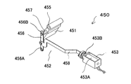
円筒回転体401に上述の如くして吸着された牌10の汲み上げ許可、禁止の制御を可能とするため、円筒回転体401の周面に接近して進入口開閉機構450が設けられている。   An entrance opening / closing mechanism 450 is provided close to the peripheral surface of the cylindrical rotating body 401 in order to enable control of permitting or prohibiting the pumping of the bowl 10 adsorbed to the cylindrical rotating body 401 as described above.

進入口開閉機構450は、仕切片451を牌10の進入を許す開位置又は牌10の進入を禁止する閉位置に位置決めすることができるようにしたもので、仕切片451をリンク機構452を介してソレノイド453に連結した構成となっている。   The entrance opening / closing mechanism 450 is configured such that the partition piece 451 can be positioned at an open position that allows entry of the cage 10 or a closed position that prohibits entry of the cage 10, and the partition piece 451 is interposed via the link mechanism 452. The solenoid 453 is connected.

図8を参照して進入口開閉機構450について説明する。仕切片451は板状部材であり、支持軸454に揺動自在に取り付けられている(図5参照)。そして、仕切片451には仕切片451を開閉駆動するためのソレノイド453がリンク機構452を介して連結されている。図5及び図8に示すように、仕切片451の上部にはスリーブ455が設けられており、案内部材501と反対側に設けた側壁との間に設けた支持軸454にスリーブ455が挿通することによって仕切片451が揺動自在に支持されている。リンク機構452の短いリンク456の下端456Aは案内部材501に回動自在に支持され上端456Bには支軸457が設けられていて、支軸457は仕切片451内に適当な深さではまっている。ソレノイド453のプランジャー453Aにはコイルバネ453Bが設けられており常に長いリンク458を前方に押している。これによりソレノイド453に通電すると長いリンク458がソレノイド453側に引かれて仕切片451はソレノイド453側に回動し、牌10の進入を禁止する閉位置に位置決めされる。また、ソレノイド453への通電を中止すると長いリンク458がコイルバネ453Bによって前方に押されて仕切片451はソレノイド453から離れる方向に回動し、牌10の進入を許可する開位置に位置決めされる。   The entrance opening / closing mechanism 450 will be described with reference to FIG. The partition piece 451 is a plate-like member and is swingably attached to the support shaft 454 (see FIG. 5). A solenoid 453 for opening and closing the partition piece 451 is connected to the partition piece 451 via a link mechanism 452. As shown in FIGS. 5 and 8, a sleeve 455 is provided on the upper portion of the partition piece 451, and the sleeve 455 is inserted into the support shaft 454 provided between the guide member 501 and the side wall provided on the opposite side. As a result, the partition piece 451 is swingably supported. The lower end 456A of the short link 456 of the link mechanism 452 is rotatably supported by the guide member 501, and the support shaft 457 is provided at the upper end 456B. The support shaft 457 is held at an appropriate depth in the partition piece 451. Yes. The plunger 453A of the solenoid 453 is provided with a coil spring 453B and always pushes the long link 458 forward. As a result, when the solenoid 453 is energized, the long link 458 is pulled to the solenoid 453 side, and the partition piece 451 rotates to the solenoid 453 side, and is positioned at the closed position where the entry of the rod 10 is prohibited. When the energization of the solenoid 453 is stopped, the long link 458 is pushed forward by the coil spring 453B, and the partition piece 451 rotates in a direction away from the solenoid 453, and is positioned at an open position that allows the rod 10 to enter.

ここで、図3を参照して牌10がターンテーブル101から汲上機構200に移動してくるまでの状態について説明する。ターンテーブル101の下面に設けた牌反転用磁石104の極性は、字面を下にしている平伏牌を反転するように定められている。上述の例で言えば、S極を上側にして設置される。この牌反転用磁石104の作用によって、ターンテーブル101の周縁付近を移動する牌のうち、字面を下にしている牌10はこの牌反転用磁石104の頭上において反発力を受けて反転し、字面が上面側となる。   Here, with reference to FIG. 3, a state until the rod 10 moves from the turntable 101 to the pumping mechanism 200 will be described. The polarity of the heel reversing magnet 104 provided on the lower surface of the turntable 101 is determined so as to reverse the flat prone sword with the character face down. If it says in the above-mentioned example, it will install with the S pole on the upper side. Of the scissors that move around the periphery of the turntable 101 by the action of the scissor reversing magnet 104, the scissors 10 with the face down are reversed by receiving a repulsive force on the head of the reversing magnet 104. Is the upper surface side.

円筒回転体401の手前には、ターンテーブル101から牌の厚さ分よりやや高く離れた位置に、外壁102から内側に向かって突設した湾曲状の障害壁113が設けられており、ターンテーブル101の周縁を移動している牌10のうち、平伏牌においては容易に障害壁113の下を通過できるようにし、字面を横に向けた状態の立牌は、この障害壁113に邪魔されて転倒、又は、立牌状態で湾曲縁に沿って移動するようになっている。そして字面を上にした牌10は円筒回転体401下方に到達するようになっている。   In front of the cylindrical rotating body 401, a curved obstacle wall 113 projecting inward from the outer wall 102 is provided at a position slightly higher than the thickness of the ridge from the turntable 101. Among the ridges 10 that move around the periphery of the 101, the flat prone lantern can easily pass under the obstacle wall 113, and the standing wall with the character face facing sideways is obstructed by the obstacle wall 113. It moves along the curved edge in a fall or standing state. The ridge 10 with the character face up reaches the lower part of the cylindrical rotating body 401.

図9を参照してターンテーブル101上から牌が汲み上げられる際の汲上機構200の一連の動作について説明する。円筒回転体401の吸着面401Bがターンテーブル101の面と対向している状態のとき、ターンテーブル101上に字面を上側にして載っている牌10が、ターンテーブル101と円筒回転体401の吸着面401Bとの間に進入してくると、円筒回転体401内の吸着面401B下方に埋設されている磁石401Cと牌10内の磁石11との間に磁気吸引力が働き、牌10が吸着面401Bに吸着される。牌10を吸着面401Bに吸着した円筒回転体401がX方向に回転することにより牌10は汲み上げられる。   With reference to FIG. 9, a series of operations of the pumping mechanism 200 when the kite is pumped from the turntable 101 will be described. When the suction surface 401 </ b> B of the cylindrical rotating body 401 faces the surface of the turntable 101, the rod 10 placed on the turntable 101 with the character surface facing upward attracts the turntable 101 and the cylindrical rotating body 401. When it enters between the surface 401B, a magnetic attraction force acts between the magnet 401C embedded below the attraction surface 401B in the cylindrical rotating body 401 and the magnet 11 in the rod 10, and the rod 10 is attracted. Adsorbed to the surface 401B. The cylinder 10 is pumped up by the rotation of the cylindrical rotating body 401 that adsorbs the paddle 10 to the suction surface 401B in the X direction.

汲上機構200によって汲み上げた牌10を縦長方向に整列させるための整列機構500について説明する。整列機構500は、案内部材501と誘導路504とを備えて成っている。汲上機構200によって汲み上げられた牌10は、案内部材501によってその縦長の方向に進行するように向きを変更しつつ誘導路504に送り込まれる構成となっている。   An alignment mechanism 500 for aligning the scissors 10 pumped up by the pumping mechanism 200 in the longitudinal direction will be described. The alignment mechanism 500 includes a guide member 501 and a guide path 504. The scissors 10 pumped up by the pumping mechanism 200 is sent to the guide path 504 while changing the direction so as to advance in the longitudinal direction by the guide member 501.

図10及び図11を参照して、吸着面401Bに様々な角度にて吸着した牌10が、整列機構500により縦長方向に整列する動作について説明する。案内部材501の入り口付近で吸着面401Bからはみ出た側面が、案内部材先端502に接触して抵抗を受けるが、牌10に埋設されている磁石11の中心が、円筒回転体401に埋設されている磁石401Cの中心に吸引されて回転しながら向きを変え、当該側面が案内部材501の内壁面501Aと並行状態になって整列機構500の内部に進入する。   With reference to FIG.10 and FIG.11, the operation | movement in which the scissors 10 attracted | sucked to the adsorption | suction surface 401B at various angles aligns in the longitudinal direction by the alignment mechanism 500 is demonstrated. The side surface that protrudes from the attracting surface 401B near the entrance of the guide member 501 contacts the guide member tip 502 and receives resistance, but the center of the magnet 11 embedded in the cage 10 is embedded in the cylindrical rotating body 401. The magnet is attracted to the center of the magnet 401C and changes its direction while rotating, and the side surface enters a state parallel to the inner wall surface 501A of the guide member 501 and enters the alignment mechanism 500.

図10は牌の長手側面が案内部材先端502に接触する様子を示したもので牌10は縦長の状態で整列機構500の内部に進入する。この状態で進入した牌10は案内部材501の途中に用意されている切欠503を通過して上部に到達する。案内部材501の内壁は上部付近にて緩やかに外側に向かっていて、牌10は向きを外側に向けると共に吸着面401Bからはみ出していく。牌10の中心が最高点を通過すると牌10は下方に向きを変えるがこのとき牌10の先頭部分は誘導路504の入り口付近に到達する。誘導路504は両側を案内部材501と側壁に囲まれたスロープからなり、図示するようにスロープ先端の一部は溝401A内に突出している。案内部材501によって吸着面401Bから外側に逸脱した牌10の先端はこのスロープ先端を跨ぐようにして誘導路504内に進入する。   FIG. 10 shows a state in which the longitudinal side surface of the heel contacts the guide member tip 502, and the heel 10 enters the alignment mechanism 500 in a vertically long state. The scissors 10 entering in this state passes through a notch 503 prepared in the middle of the guide member 501 and reaches the upper part. The inner wall of the guide member 501 is gradually outward in the vicinity of the upper portion, and the flange 10 is directed outward and protrudes from the adsorption surface 401B. When the center of the kite 10 passes the highest point, the kite 10 changes its direction downward. At this time, the leading portion of the kite 10 reaches the vicinity of the entrance of the guide path 504. The guide path 504 is composed of a slope surrounded on both sides by a guide member 501 and a side wall, and a part of the tip of the slope protrudes into the groove 401A as shown in the figure. The tip of the heel 10 that deviates outward from the suction surface 401B by the guide member 501 enters the guide path 504 so as to straddle the slope tip.

図11は牌10の短手側面が案内部材先端502に接触する様子を示したものである。牌10は短手側面が案内部材先端502に接触して図10の場合と同様に回転するが、牌10は傾斜部401Dを跨いだ形で横長の状態になって内部に進入する。このとき牌10に埋設されている磁石11の中心が、円筒回転体401に埋設されている磁石401Cの中心より外側に偏っているため、牌10は内側に吸引力を受け、当該側面は案内部材501の内壁面501Aに圧接した状態で整列機構500の内部に進入する。   FIG. 11 shows a state in which the short side surface of the heel 10 contacts the guide member tip 502. The saddle 10 rotates in the same manner as in FIG. 10 with the short side surface coming into contact with the guide member tip 502, but the saddle 10 enters the inside in a horizontally long state straddling the inclined portion 401D. At this time, since the center of the magnet 11 embedded in the cage 10 is biased outward from the center of the magnet 401C embedded in the cylindrical rotating body 401, the cage 10 receives an attractive force on the inside, and the side surface is guided. The member 501 enters the alignment mechanism 500 while being in pressure contact with the inner wall surface 501A.

牌10の中心が切欠503に到達すると、内壁に当接している側面は抵抗を受けているため牌10は切欠先端505を中心に回転し牌10の一部は切欠503内に進入する。このとき傾斜部401Dによって僅かに浮き上がっていた牌10の一端が傾斜部401D上を滑落して牌10の回転を加速する。なお、傾斜部401Dは回転を補助するためであって特に設けなくともよい。この状態で牌10が更に進むと、牌長手側面が切欠後端506に接触し、再度回転して長手側面を案内部材501の内壁面501Aに当接して前進する。上述の如く、様々な角度で円筒回転体401に吸着した牌10は整列機構500により一定の向きに制御される。   When the center of the scissors 10 reaches the notch 503, the side surface in contact with the inner wall receives resistance, so that the scissors 10 rotate around the notch tip 505, and a part of the scissors 10 enters the notch 503. At this time, one end of the heel 10 slightly lifted by the inclined portion 401D slides down on the inclined portion 401D to accelerate the rotation of the heel 10. Note that the inclined portion 401D is for assisting rotation and may not be provided. When the kite 10 further advances in this state, the kite longitudinal side surface comes into contact with the notch rear end 506 and rotates again to advance by contacting the longitudinal side surface with the inner wall surface 501A of the guide member 501. As described above, the kite 10 adsorbed to the cylindrical rotating body 401 at various angles is controlled in a fixed direction by the alignment mechanism 500.

図4、図5、図9に示されるように、案内部材501の頂上付近にて内壁に設られた孔内には反射型フォトセンサからなる入口センサ403が設けられており、牌10は入口センサ403によりその進入が電気的に検知される。そして円筒回転体401によって送られてきた牌10は、円筒回転体401の頂上付近において誘導路504の一端504Aにより捕捉され、円筒回転体401の回転につれて吸着面401Bより剥離され、下方に向けて傾斜している誘導路504に沿って自重によって自然落下し、振り分け機構600に向けて前進する構成となっている。   As shown in FIGS. 4, 5, and 9, an entrance sensor 403 made of a reflective photosensor is provided in a hole provided in the inner wall near the top of the guide member 501. The approach is electrically detected by the sensor 403. The bag 10 sent by the cylindrical rotating body 401 is captured by one end 504A of the guide path 504 in the vicinity of the top of the cylindrical rotating body 401, peeled off from the suction surface 401B as the cylindrical rotating body 401 rotates, and directed downward. It is configured such that it naturally falls by its own weight along the inclined guide path 504 and moves forward toward the sorting mechanism 600.

誘導路504の進行方向の延長上には、一端を回動自在に軸支した可動片601とソレノイドからなる牌反転機構650が設けられている。牌反転機構650は牌10を反転させるのに使用されるものであり、ソレノイド620によって駆動される可動片601は通常図示の位置にある。可動片601には磁石602が埋設されており、字面を下にして落下してくる牌10は、磁石602によって吸引されて可動片601上で停止するよう構成されている。牌反転機構650の動作については、後述する。
On the extension of the direction of travel of the guide path 504, there is provided a reversing mechanism 650 comprising a movable piece 601 with one end pivotably supported and a solenoid. The reversing mechanism 650 is used for reversing the reed 10, and the movable piece 601 driven by the solenoid 620 is normally in the position shown in the figure. A magnet 602 is embedded in the movable piece 601, and the scissors 10 falling with the character face down are attracted by the magnet 602 and stopped on the movable piece 601. The operation of the heel reversing mechanism 650 will be described later.

次に、振り分け機構600について説明する。振り分け機構600は、整列機構500より牌反転機構650を介して送られてきた牌10を、後で詳しく説明する載置部701の下載置台702又は上載置台703のいずれかに選択的に送り込むための機構である。振り分け機構600は、牌を移動させるために必要な円盤回転体603とその駆動機構、及び、牌の軌道を制御するための振り分け板604とその駆動機構を有している。   Next, the distribution mechanism 600 will be described. The sorting mechanism 600 selectively sends the kite 10 sent from the alignment mechanism 500 via the kite reversing mechanism 650 to either the lower mounting table 702 or the upper mounting table 703 described later in detail. Mechanism. The distribution mechanism 600 includes a disk rotating body 603 necessary for moving the kite and its drive mechanism, and a distribution plate 604 for controlling the trajectory of the kite and its drive mechanism.

図12を参照して円盤回転体603について説明する。円盤回転体603は、円筒形の基部605を有しており、基部605の側面にフランジ状に薄板606が形成され、さらに薄板606上に基部605と同程度の厚さの棒状押し片607が等間隔に2個配設されており、基部605の中心は回転軸406(図5参照)に固着されている。
The disc rotating body 603 will be described with reference to FIG. The disc rotating body 603 has a cylindrical base 605, a thin plate 606 is formed in a flange shape on the side surface of the base 605, and a rod-like pressing piece 607 having a thickness similar to the base 605 is formed on the thin plate 606. Two are arranged at equal intervals, and the center of the base portion 605 is fixed to the rotating shaft 406 (see FIG. 5).

次に、図13を参照して振り分け板604について説明する。振り分け板604は、円盤回転体603の基部605(図12参照)と同半径の仰木型状基部608を備えており、仰木型状基部608の一端を延設した平板状基部609に、側壁610及び上板611が図示の如く形成されていると共に、ストッパ612が図示の位置に設けられている。基部608の中心には孔613が形成されており、孔613内に回転軸406(図5参照)を嵌挿し、これにより振り分け板604は回転軸406によって回動自在に支持されている。
Next, the sorting plate 604 will be described with reference to FIG. The sorting plate 604 includes a base-like base 608 having the same radius as the base 605 (see FIG. 12) of the disk rotor 603, and a side wall 610 on a flat base 609 extending from one end of the base-like base 608. The upper plate 611 is formed as shown in the figure, and the stopper 612 is provided at the position shown in the figure. A hole 613 is formed at the center of the base 608, and a rotation shaft 406 (see FIG. 5) is fitted into the hole 613, whereby the sorting plate 604 is rotatably supported by the rotation shaft 406.

ここで、図4も併せて参照すると、円盤回転体603の薄板606と、振り分け板604の側壁610との間隔は牌の幅より僅かに広い程度に保持されている。そして振り分け板604は、バネ630によって常時下側に向けられていると共に、リンク615を介してソレノイド614に連結しており、ソレノイド614を駆動することにより牌の出口を上方向に変更し、前方に配設されている、後述する押出機構700の載置部701の下載置台702又は上載置台703上のいずれかに牌10を振り分けて載置することができるように構成されている。   Here, referring also to FIG. 4, the distance between the thin plate 606 of the disc rotating body 603 and the side wall 610 of the sorting plate 604 is maintained to be slightly wider than the width of the ridge. The distribution plate 604 is always directed downward by a spring 630 and is connected to a solenoid 614 via a link 615. By driving the solenoid 614, the outlet of the bag is changed upward, It is comprised so that the cage | basket 10 can be distributed and mounted in either on the lower mounting base 702 or the upper mounting base 703 of the mounting part 701 of the extrusion mechanism 700 mentioned later arrange | positioned.

上述の如く構成されている振り分け機構600による牌の振り分け動作について説明する。図13には振り分け板604が下載置台702に向けられているときの状態が示されており、汲み上げ途中の牌10と誘導路504上の牌10と棒状押し片607に後端を押されて移送(移送手段)されている牌10とが示されている。ここでは、磁石401Cと棒状押し片607との位相関係がほぼ90度の状態が示されている。
A description will be given of the sorting operation of the bag by the sorting mechanism 600 configured as described above. FIG. 13 shows a state where the sorting plate 604 is directed to the lower mounting table 702. The rear end is pushed by the rod 10 in the middle of pumping, the rod 10 on the guide path 504, and the rod-shaped pushing piece 607. A trough 10 being transported (transporting means) is shown. Here, a state in which the phase relationship between the magnet 401C and the rod-shaped pressing piece 607 is approximately 90 degrees is shown.

図14には、図13において棒状押し片607に押されていた牌10が下載置台702に押し込まれたときの状態が示されており、このとき誘導路504上にあった牌10は可動片601内の磁石602に吸引され、汲み上げ途中であった牌10は円筒回転体401上に汲み上げられている。   FIG. 14 shows a state in which the rod 10 pushed by the rod-like pushing piece 607 in FIG. 13 is pushed into the lower mounting table 702. At this time, the rod 10 on the guide path 504 is a movable piece. The bag 10 that has been attracted by the magnet 602 in the 601 and is being pumped is being pumped onto the cylindrical rotating body 401.

図15及び図16は振り分け板604が上載置台703に向けられているときの牌の移送状態を説明するためのものである。図15において、可動片601上にある牌10は、その後端下側を棒状押し片607によって押し上げられるようにして磁石602から剥離させられ、振り分け板604の平板上基部609上に押し出される。そして次に、図16に示される如く、牌10は押し片607によって平板上基部609上で前方に押されて前進し、さらに押し片607に押されて牌10の先端が上載置台703上の中心まで進むと、載置部701の上部片704内にS極を下にして埋設されている磁石705によって吸引され、上載置台703上の所定の位置に載置される。   FIG. 15 and FIG. 16 are for explaining a state in which the basket is transferred when the sorting plate 604 is directed to the upper mounting table 703. In FIG. 15, the rod 10 on the movable piece 601 is peeled off from the magnet 602 so that the lower side of the rear end is pushed up by the rod-like push piece 607, and pushed out onto the flat plate base 609 of the sorting plate 604. Next, as shown in FIG. 16, the rod 10 is pushed forward by the push piece 607 on the flat base 609 and further pushed by the push piece 607 so that the tip of the rod 10 is placed on the upper mounting table 703. When going to the center, it is attracted by the magnet 705 embedded in the upper piece 704 of the mounting portion 701 with the south pole facing down, and is mounted at a predetermined position on the upper mounting table 703.

次に、図17乃至図19を参照し、牌反転機構650により振り分け機構600に進入する前に牌10を反転させる場合の動作について説明する。まず、図17において、牌10が円筒回転体401により汲み上げられ、牌10の汲み上げが入口センサ403によって検知されると、この検知結果に応答してソレノイド410が作動し、仕切り片451が牌10の通過を禁止する閉位置とされる。すなわち、牌反転機構650により牌10を反転させる場合には、反転させるべき牌が入口センサ403により検出されたことに応答して進入口開閉機構450を動作させて仕切り片451を閉位置に切り換える。このとき、牌反転機構650のソレノイド620が作動して可動片601は図示の位置に後退し誘導路504の下方に位置して間隙616が形成される。この状態において、仕切り片451は開位置とされ、牌10を汲み上げる誘導路504を落下滑走してくる牌10は間隙616内に落下する。   Next, with reference to FIG. 17 to FIG. 19, an operation when the bag 10 is reversed before entering the sorting mechanism 600 by the bag reversing mechanism 650 will be described. First, in FIG. 17, when the scissors 10 are pumped up by the cylindrical rotating body 401 and the scooping up of the scissors 10 is detected by the inlet sensor 403, the solenoid 410 is activated in response to the detection result, and the partition piece 451 is moved to the scissors 10 The closed position prohibits the passage of. That is, when reversing the reed 10 by the reed reversing mechanism 650, the entrance opening / closing mechanism 450 is operated in response to detection of the reed to be reversed by the entrance sensor 403 to switch the partition piece 451 to the closed position. . At this time, the solenoid 620 of the heel reversing mechanism 650 is actuated so that the movable piece 601 moves backward to the position shown in the figure and is positioned below the guide path 504 to form a gap 616. In this state, the partition piece 451 is set to the open position, and the kite 10 that falls and slides on the guide path 504 for pumping the kite 10 falls into the gap 616.

図18は、間隙616内に落下した牌10がストッパ612によって受け止められている状態が示されている。図18に示すようにストッパ612は、右肩上りに傾斜していて牌10が受け止められたときに牌10が左に傾いた状態で静止するように構成されている。なお、補助的に、振り分け板604の仰木型状基部608の裏側の適当な位置に磁石を埋設しても良い。   FIG. 18 shows a state where the kite 10 that has fallen into the gap 616 is received by the stopper 612. As shown in FIG. 18, the stopper 612 is configured so as to incline to the right shoulder and to stand still when the heel 10 is tilted to the left when the heel 10 is received. In addition, a magnet may be embedded in an appropriate position on the back side of the supine base 608 of the sorting plate 604 as an auxiliary.

図19は、ストッパ612上に載置されていた牌10が棒状押し片607によって字面10Bを上にした状態で仰木型状基部608に沿って移送される様子が示されている。牌10は字面10Bが上にされた状態で移動されていき、懸賞牌となるものである。この牌10は、この後、平板状基部609上を移動し、下載置台702上に載置されるが、牌10の平板状基部609から下載置台702への移動については、図13及び図14を用いて説明した場合と全く同様であるので、ここでの詳しい説明は省略する。   FIG. 19 shows a state in which the bag 10 placed on the stopper 612 is transferred along the supine-shaped base 608 in a state in which the character surface 10 </ b> B is raised by the rod-shaped push piece 607. The heel 10 is moved in a state where the character face 10B is faced up, and becomes a sweepstakes heel. The scissors 10 then moves on the flat base 609 and is placed on the lower mounting table 702. The movement of the scissors 10 from the flat base 609 to the lower mounting base 702 is shown in FIGS. Since this is exactly the same as the case described with reference to FIG.

上述の如くして牌10は振り分け機構600から押出機構700の載置部701の下載置台702又は上載置台703上へ載置される。図4を参照すると、振り分け機構600によって振り分けられた牌10は、振り分け機構600から牌10の進行方向上に設けられている押出機構700に移送される。   As described above, the rod 10 is placed from the sorting mechanism 600 onto the lower placing table 702 or the upper placing table 703 of the placing unit 701 of the pushing mechanism 700. Referring to FIG. 4, the basket 10 sorted by the sorting mechanism 600 is transferred from the sorting mechanism 600 to an extrusion mechanism 700 provided in the traveling direction of the basket 10.

図20は押出機構700の載置部701の斜視図、図21は押出機構700の斜視図、図22は押出機構700の立面図である。図13、図20〜図22を参照して押出機構700について説明する。   20 is a perspective view of the mounting portion 701 of the extrusion mechanism 700, FIG. 21 is a perspective view of the extrusion mechanism 700, and FIG. 22 is an elevation view of the extrusion mechanism 700. The extrusion mechanism 700 will be described with reference to FIGS. 13 and 20 to 22.

押出機構700は、載置部701と押出部730とを備えて成っている。押出機構700の載置部701は牌10を載置するための下載置台702と上載置台703とを備えた2層構造部を有しており、下載置台702及び上載置台703の突き当たりにはストッパとして働く側壁706が設けられている。棒状押し片607によっていずれの載置台702、703に押し込まれた牌10も側壁706によって制止されるようになっている。上載置台703の上方には、牌10の厚さ分より若干大きい程度の間隔をあけて上部片704が設けられている。このようにして載置部701には牌10を収容するための上部空間741と下部空間742とが形成されている。   The extrusion mechanism 700 includes a placement unit 701 and an extrusion unit 730. The placing portion 701 of the extrusion mechanism 700 has a two-layer structure portion including a lower placing table 702 and an upper placing table 703 for placing the basket 10. A stopper is provided at the end of the lower placing table 702 and the upper placing table 703. Side walls 706 are provided that serve as The eaves 10 pushed into any of the mounting tables 702 and 703 by the rod-shaped pushing piece 607 is stopped by the side wall 706. An upper piece 704 is provided above the upper mounting table 703 with an interval slightly larger than the thickness of the flange 10. In this manner, the placement portion 701 is formed with an upper space 741 and a lower space 742 for accommodating the bag 10.

上部空間741において、側壁706と対向する開口から牌10が振り分け機構600により上部空間741内に押し込まれてきて上載置台703上に載置される。   In the upper space 741, the bag 10 is pushed into the upper space 741 by the sorting mechanism 600 from the opening facing the side wall 706 and placed on the upper placement table 703.

下部空間742においても、同様に、側壁706と対向する開口から牌10が振り分け機構600により下部空間742内に押し込まれてきて下載置台702上に載置される。側壁706には反射型フォトセンサ707及び708が設けられており、下載置台702上に載置された牌10は反射型フォトセンサ707にて、また上載置台703上に載置された牌10は反射型フォトセンサ708にて検知される。   Similarly, in the lower space 742, the bag 10 is pushed into the lower space 742 by the distribution mechanism 600 from the opening facing the side wall 706 and placed on the lower mounting table 702. Reflective photosensors 707 and 708 are provided on the side wall 706, and the cage 10 placed on the lower mounting table 702 is reflected by the reflective photosensor 707 and the cage 10 placed on the upper mounting table 703 is It is detected by a reflective photosensor 708.

載置部701に隣接して牌10の進入方向に対して左側に押出部730が配設されている。押出部730は、上側押し込み片709及び下側押し込み片710を備えており、各押し込み片709及び710は、L字状の連結アーム712の一端に上部空間741及び下部空間742にそれぞれ対向するように取り付けられており、連結アーム712の他端は摺動片711に連結されている。摺動片711は水平に保持された支持棒713に水平摺動自在に嵌挿されており、一方、連結アーム712の下側にはコロ714があって連結アーム712の水平運動を保持すると共に、図22に示すように各押し込み片709、710が取り付けられている連結アーム712の一端は、載置部701に水平に保持された支持棒712Aに挿通されていて、押し込み片709、710の横振れを抑止している。(図9参照)。   An extruding portion 730 is disposed adjacent to the placing portion 701 on the left side with respect to the approach direction of the basket 10. The pushing portion 730 includes an upper pushing piece 709 and a lower pushing piece 710, and each pushing piece 709 and 710 is opposed to the upper space 741 and the lower space 742 at one end of the L-shaped connecting arm 712, respectively. The other end of the connecting arm 712 is connected to the sliding piece 711. The sliding piece 711 is inserted into a horizontally supported support bar 713 so as to be horizontally slidable. On the other hand, there is a roller 714 below the connecting arm 712 to hold the horizontal movement of the connecting arm 712. As shown in FIG. 22, one end of the connecting arm 712 to which the pushing pieces 709 and 710 are attached is inserted into a support bar 712 </ b> A held horizontally by the mounting portion 701, and the pushing pieces 709 and 710 are inserted. Sideways are suppressed. (See FIG. 9).

ここで図4も併せて参照すると、駆動用歯車201の上方には2つのコロ715を等間隔に配設した回転板716が支軸205に固着されており、一方、摺動片711の下方には当て板717が突設形成されていて、コロ715が矢印の向きに回転して当て板717に当接している間、摺動片711は点線で示す位置に前進する。摺動片711の上部には戻しバネ718があって、コロ715が当て板717からはずれると同時に摺動片711は元位置に後退する。コロ715と棒状押し片607の位相関係は棒状押し片607が下載置台702上に牌10を押し込んだ直後にその棒状押し片607がほぼ水平になった時に、コロ715が当て板717に当接するように構成されている。
Referring now also FIG. 4 together, and the rotating plate 716 is fixed to the supporting lifting shaft 205 above the driving gear 201 which is disposed two rollers 715 at equal intervals, whereas, the sliding pieces 711 A contact plate 717 is formed so as to protrude downward, and while the roller 715 rotates in the direction of the arrow and contacts the contact plate 717, the sliding piece 711 advances to a position indicated by a dotted line. There is a return spring 718 at the upper part of the sliding piece 711, and at the same time the roller 715 is detached from the contact plate 717, the sliding piece 711 is retracted to the original position. The phase relationship between the roller 715 and the rod-shaped pushing piece 607 is that the roller 715 comes into contact with the contact plate 717 when the rod-like pushing piece 607 is almost horizontal immediately after the rod-like pushing piece 607 pushes the collar 10 onto the lower mounting table 702. It is configured as follows.

押出機構700は上述の如く構成されているので、上載置台703上に載置された牌10は、上載置台703上に押し込まれた直後に、上側押し込み片709がX方向(図22参照)に水平移動して点線で示す位置まで前進するので、上載置台703上の上部空間741内から脱出して押出機構700から押し出される。牌10が下部空間742内の下載置台702上に載置された場合には、牌10が下載置台702上に押し込まれた直後に下側押込片710がX方向に水平移動して点線で示す位置まで前進するので、下載置台702上の下部空間742内から脱出して押出機構700から押し出されるようになっている。   Since the pushing mechanism 700 is configured as described above, the upper pushing piece 709 is placed in the X direction (see FIG. 22) immediately after the rod 10 placed on the upper placing table 703 is pushed onto the upper placing table 703. Since it moves horizontally and moves forward to the position indicated by the dotted line, it escapes from the upper space 741 on the upper mounting table 703 and is pushed out from the extrusion mechanism 700. When the cage 10 is placed on the lower mounting table 702 in the lower space 742, immediately after the cage 10 is pushed onto the lower mounting table 702, the lower pushing piece 710 moves horizontally in the X direction and is indicated by a dotted line. Since it moves forward to the position, it escapes from the lower space 742 on the lower mounting table 702 and is pushed out from the pushing mechanism 700.

図22に示されているように、押出機構700から押し出された牌10を順次受け取って整列させるため、押出機構700の牌10の押し出し側で、載置部701を挟みその反対側には、待機機構800が設けられている。
As shown in FIG. 22, in order to sequentially receive and align the rods 10 extruded from the extrusion mechanism 700, on the side of the extrusion mechanism 700 on the extrusion side of the rod 10, with the mounting portion 701 sandwiched therebetween, A standby mechanism 800 is provided.

図22を参照して待機機構800について説明する。待機機構800は、載置部701に一旦載置された牌10が押出部730によって押し出されたときに、この押し出された牌10を受け取って順次1段又は2段に整列させていき、これにより所要の配牌ブロック又は2段積牌ブロックを形成して待機させておくための機構である。待機機構800は1段積の配牌ブロックが形成される配牌台801及び2段積牌ブロックが形成される待機台802とを備えて成っており、すなわち、待機機構には1段積の配牌ブロックが形成される第1の台(配牌台801)と2段積牌ブロックが形成される第2の台(待機台802)とが設けられ、待機台802は後述する駆動機構に連結されている。待機台802が原点位置(通常位置)にある時には、待機台802は下載置台702と同一レベル、又は僅かに低いレベルにある。一方、配牌台801は後述する駆動機構に連結しており、配牌台801が原点位置(通常位置)にあるときには、配牌台801は上載置台703と同一レベル、又は僅かに低いレベルに静止している。
The standby mechanism 800 will be described with reference to FIG. When the sputum 10 once placed on the placing section 701 is pushed out by the push-out section 730, the standby mechanism 800 receives the pushed-out spear 10 and sequentially arranges it in one or two stages. Is a mechanism for forming a required layout block or a two-stage stacking block and waiting. The standby mechanism 800 includes a layout table 801 on which a one-stage product layout block is formed and a standby table 802 on which a two-stage product layout block is formed . A first table (laying table 801) on which a layout block is formed and a second table (standby table 802) on which a two-stage stacking block is formed are provided . The standby table 802 is connected to a drive mechanism described later. It is connected. When the standby table 802 is at the origin position (normal position), the standby table 802 is at the same level as the lower mounting table 702 or at a slightly lower level. On the other hand, the layout table 801 is connected to a drive mechanism to be described later, and when the layout table 801 is at the origin position (normal position), the layout table 801 is at the same level as or slightly lower than the upper mounting table 703. It is stationary.

押出機構700の下載置台702上に振り分け載置された牌10は下側押し込み片710によって押し出されて下載置台702に隣接する待機台802上に移動する。そして次の牌10が下載置台702上に載置され下側押し込み片710によって押し出されてくると、先に待機台802上に載せられていた牌10は次の牌10に押圧され、図22のX方向である下側押し込み片710の押出方向に牌1つ分だけ進む。上述の動作が所要の回数繰り返し行われることにより、下載置台702上に振り分け載置された牌10が待機台802上に、先ず、所要の数だけ一段に整列される。   The trough 10 placed and distributed on the lower mounting table 702 of the extrusion mechanism 700 is pushed out by the lower pushing piece 710 and moves onto the standby table 802 adjacent to the lower mounting table 702. Then, when the next bag 10 is placed on the lower mounting table 702 and pushed out by the lower push-in piece 710, the bag 10 previously placed on the standby table 802 is pressed by the next bag 10, and FIG. In the X direction, the lower pushing piece 710 is advanced by one 牌 in the pushing direction. By repeatedly performing the above-described operation a required number of times, the cages 10 that are sorted and placed on the lower placement table 702 are first arranged in a single row on the standby table 802 by the required number.

このようにして一段目の整列が終了すると、待機台802は牌10の厚さ分だけ下降し、その後一段目の牌10の上に上述と全く同様にして2段目に整列させるための牌10が下載置台702から下側押し込み片710により順次押し出される。一段目の牌10の上に載せられた牌10は、隣り合って押圧してくる牌10により一段目の牌上を下側押し込み片710の押出方向に移動する。この動作が所要の回数繰り返されて一段目の牌10上に二段目の牌10が整列され、これにより所要の2段積牌ブロックが形成される。   When the first stage alignment is completed in this way, the stand 802 is lowered by the thickness of the ridge 10, and then the ridge for aligning the second stage on the first tier 10 in the same manner as described above. 10 are sequentially pushed out from the lower mounting table 702 by the lower pushing piece 710. The heel 10 placed on the first-stage ridge 10 is moved in the push-out direction of the lower pushing piece 710 on the first-stage ridge by the ridge 10 pressing adjacently. This operation is repeated a required number of times so that the second-stage ridges 10 are aligned on the first-stage ridges 10, thereby forming the required two-stage pile block.

一方、上載置台703上に振り分け載置された牌10は、上側押し込み片709によって押し出されて配牌台801上に移動する。そして次の牌10が上載置台703上に載置され上側押し込み片709によって押し出されると、先に配牌台801の上に載せられていた牌10は、次に押し出されてきた牌10によって押圧され、上側押込片709の押出方向に牌1つ分だけ移動する。この動作が所要の回数繰り返し行われることにより、上載置台703上に振り分け載置された牌10は配牌台801上に整列され、所要の数の牌が1段1列の状態で形成され、これにより所要の配牌ブロックが形成される。以上の説明から判るように、振り分け機構600及び押出機構700によって、整列機構500から送り出される牌10を配牌台801(第1の台)上又は待機台802(第2の台)上のいずれか一方に送給するための選択送給機構を構成している。   On the other hand, the basket 10 distributed and placed on the upper placing table 703 is pushed out by the upper pushing piece 709 and moves onto the serving table 801. Then, when the next rod 10 is placed on the upper mounting table 703 and pushed out by the upper pushing piece 709, the rod 10 previously placed on the table 801 is pressed by the next pushed rod 10. Then, the upper pushing piece 709 moves by one hook in the pushing direction. By repeating this operation a required number of times, the baskets 10 that are distributed and placed on the upper mounting table 703 are aligned on the layout table 801, and the required number of baskets are formed in a state of one row and one row, Thereby, a required layout block is formed. As can be understood from the above description, the sorting mechanism 600 and the pushing mechanism 700 cause the basket 10 delivered from the alignment mechanism 500 to be placed on the layout table 801 (first table) or the standby table 802 (second table). A selective feeding mechanism for feeding to either of them is configured.

上述した待機台802は、押出機構700から牌を受け取るためだけでなく、待機台802上に形成された2段積牌ブロックを後述する昇降台901に移載させるため、上下動するようになっている。また、配牌台801は、待機台802が上方へ移動する場合に、待機台802の上方への移動を邪魔することがないように回動運動を行うように構成されている。   The standby table 802 described above moves not only to receive the soot from the extrusion mechanism 700, but also to move the two-stage stacking block formed on the standby table 802 to an elevator table 901, which will be described later, to move up and down. ing. In addition, when the standby table 802 moves upward, the layout table 801 is configured to rotate so as not to obstruct the upward movement of the standby table 802.

図23、図24を参照して待機台802を上下動させるための構成について説明する。待機台802は下面2カ所において直方体状の保持部材803に固定されており、この保持部材803の中央に設けたガイド孔がベース板115に垂直に立てられた支持軸804に嵌挿されており、これにより保持部材803は待機台802を上下摺動自在に支持する。保持部材803の下方側面には横溝805が形成されており、この横溝805には、アーム806の一端に設けたコロ807が嵌合している。   A configuration for moving the stand 802 up and down will be described with reference to FIGS. 23 and 24. The standby base 802 is fixed to a rectangular parallelepiped holding member 803 at two lower surfaces, and a guide hole provided at the center of the holding member 803 is fitted into a support shaft 804 that stands vertically to the base plate 115. Thus, the holding member 803 supports the standby table 802 so as to be slidable up and down. A lateral groove 805 is formed on the lower side surface of the holding member 803, and a roller 807 provided at one end of the arm 806 is fitted in the lateral groove 805.

アーム806はベース板115をコ字状に折り曲げた側板840上に設けた固定軸808に回動自在に支持されていると共に付勢バネ809によって下方に付勢されている。アーム806の上方には、ベース板115の側板を貫通して回転自在に支持されているカム軸810が設けられている。アーム806のもう一方の端にはコロ811が設けられており、コロ811はカム軸810上に配設されたカム812に当接するように設けられている。   The arm 806 is rotatably supported by a fixed shaft 808 provided on a side plate 840 obtained by bending the base plate 115 into a U shape, and is biased downward by a biasing spring 809. Above the arm 806, a cam shaft 810 that is rotatably supported through the side plate of the base plate 115 is provided. A roller 811 is provided at the other end of the arm 806, and the roller 811 is provided so as to contact a cam 812 disposed on the cam shaft 810.

カム軸810は歯車813、814を介して駆動モータ815に連結しており、駆動モータ815を起動してカム軸810を一回転させると、待機台802は図で点線と実線とで示される間を1回上下運動を行う。また、カム軸810の一方の端には回転角を検出して駆動モータ815を停止制御するために、切欠を有したセンサ板816とフォトインタラプタ818a〜818cが配設されていて、この3組のセンサにより検出されたカム軸810の回転角に応じて待機台802の原点位置、下降位置、及び上昇位置が検出される。   The camshaft 810 is connected to a drive motor 815 via gears 813 and 814. When the drive motor 815 is activated to rotate the camshaft 810 once, the standby base 802 is shown by a dotted line and a solid line in the figure. Move up and down once. In addition, a sensor plate 816 having notches and photo interrupters 818a to 818c are arranged at one end of the camshaft 810 to detect and stop the rotation of the drive motor 815. The origin position, the lowered position, and the raised position of the standby base 802 are detected according to the rotation angle of the cam shaft 810 detected by the sensor.

次に、図24及び図25を参照して配牌台801の回動運動について説明する。配牌台801はベース板115の側板840に設けた固定軸820によって回動自在に支持されたアーム821の先端に固定されている。アーム821はバネ823によってばね付勢されている。アーム821のもう一方の端にはコロ822があり、カム軸810上に設けたカム812に当接していて、カム軸810を矢印の方向に一回転すると配牌台801は点線と実線で示される位置の間を回動して往復動する。   Next, the rotational movement of the layout table 801 will be described with reference to FIGS. The table 801 is fixed to the tip of an arm 821 that is rotatably supported by a fixed shaft 820 provided on the side plate 840 of the base plate 115. The arm 821 is spring-biased by a spring 823. There is a roller 822 at the other end of the arm 821, which is in contact with a cam 812 provided on the cam shaft 810. When the cam shaft 810 rotates once in the direction of the arrow, the layout table 801 is indicated by a dotted line and a solid line. It reciprocates by rotating between the positions.

このようにして待機台802の垂直往復動と、配牌台801の回転往復動とを一本のカム軸810の一回転によって行うもので、カム軸810とカム812との関係について以下に説明する。   Thus, the vertical reciprocation of the stand 802 and the rotational reciprocation of the layout table 801 are performed by one rotation of one cam shaft 810, and the relationship between the cam shaft 810 and the cam 812 will be described below. To do.

カム軸810が原点位置にあるとき、待機台802は前述したように下載置台702の高さにあり、また、配牌台801は上載置台703の高さ位置にある。待機台802上に1段目(下段)の整列牌が形成されると駆動モータ815を起動してカム軸810を矢印の向きに回転させ、待機台802を下降させる。配牌台801は下降位置を維持する。待機台802が牌1個分下降した下降位置にてフォトインタラプタ818bはセンサ板816の切欠の開始端を検出して駆動モータ815を停止する。この状態にて待機台802上に2段目(上段)の整列牌が形成される。この状態で配牌台801上には配牌が、待機台802上には2段積み牌が形成される。   When the camshaft 810 is at the origin position, the standby table 802 is at the height of the lower mounting table 702 as described above, and the layout table 801 is at the height position of the upper mounting table 703. When the first stage (lower stage) alignment rod is formed on the standby table 802, the drive motor 815 is activated to rotate the cam shaft 810 in the direction of the arrow, and the standby table 802 is lowered. The serving table 801 maintains the lowered position. The photo interrupter 818b detects the start end of the cutout of the sensor plate 816 and stops the drive motor 815 at the lowered position where the stand 802 is lowered by one 牌. In this state, a second-stage (upper-stage) alignment rod is formed on the stand 802. In this state, a layout is formed on the layout table 801 and a two-stage stack is formed on the standby table 802.

以上の説明から判るように、振り分け機構600、押出機構700及び待機機構800によって、整列機構500から送り出される牌10を第1の台である配牌台801上に配牌ブロックとして形成してそこに待機させ、整列機構500から送り出される牌10を第2の台である待機台802上に2段積牌ブロックとして形成してそこに待機させておくためのブロック形成・待機機構が構成されている。   As can be seen from the above description, the sorting mechanism 600, the pushing mechanism 700, and the standby mechanism 800 form the basket 10 delivered from the alignment mechanism 500 as a layout block on the layout table 801 that is the first platform. The block forming / standby mechanism is configured to form the cocoon 10 sent out from the alignment mechanism 500 as a two-stage stacked cocoon block on the standby table 802 as the second table, and to wait there. Yes.

このようにして、配牌台801上に形成されて待機している配牌ブロックと、待機台802上に形成されて待機している2段積牌ブロックとは、移載機構として働く押し板機構1000により選択的に昇降機構900の昇降台901上に移載される構成となっている。   In this way, the waiting block formed on the waiting table 801 and waiting and the two-stage loading block formed on the waiting stand 802 and waiting are the push plates that serve as a transfer mechanism. The mechanism 1000 is selectively transferred onto the lifting platform 901 of the lifting mechanism 900.

図3から判るように、上述の如く動作する配牌台801、待機台802上に形成された配牌ブロック、又は2段積牌ブロックを受け取り天板4上のレベルまで上昇させるため、配牌台801、待機台802の近傍に昇降台機構900、及び押板機構1000が設けられている。図26も併せて参照すると、配牌台801、待機台802と昇降台機構900、押板機構1000との概略構成図が示されている。   As can be seen from FIG. 3, the layout table 801 operating as described above, the layout block formed on the standby table 802, or the two-stage stacking block is received and raised to the level on the top 4. A lift mechanism 900 and a push plate mechanism 1000 are provided in the vicinity of the table 801 and the standby table 802. Referring also to FIG. 26, a schematic configuration diagram of the layout table 801, the standby table 802, the lifting platform mechanism 900, and the push plate mechanism 1000 is shown.

図26には、配牌台801及び待機台802に牌ブロックがいずれも形成されていない場合の状態が示されている。配牌台801、待機台802の本体2の中心側には上下動する昇降台901が設けられており、配牌台801の本体2の周縁側には、前後に水平移動する押し板1004を含む押板機構1000が設けられている。   FIG. 26 shows a state where no basket block is formed on the layout table 801 and the standby table 802. An elevating table 901 that moves up and down is provided at the center side of the main body 2 of the layout table 801 and the standby table 802, and a push plate 1004 that horizontally moves back and forth is provided on the peripheral side of the main body 2 of the layout table 801. A push plate mechanism 1000 is provided.

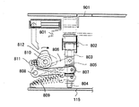
図27は昇降台機構900の斜視図、図28は昇降台機構900の正面図である。図24、図27、図28を参照して昇降台機構900について説明する。L字状の昇降台901のほぼ中央には保持部材902が固定されている。保持部材902にはガイド孔が設けられており、このガイド孔にはベース板115に垂直に固定された支軸903が挿通されているので、保持部材902及び昇降台901は支軸903に沿って上下に運動することができる。保持部材902とベース板115の間には引張りバネ904が設けられており、引張りバネ904により昇降台901は常にベース板115に向かう方向に付勢されている。   FIG. 27 is a perspective view of the lifting platform mechanism 900, and FIG. 28 is a front view of the lifting platform mechanism 900. The lifting platform mechanism 900 will be described with reference to FIGS. 24, 27, and 28. A holding member 902 is fixed substantially at the center of the L-shaped lifting platform 901. A guide hole is provided in the holding member 902, and a support shaft 903 fixed perpendicularly to the base plate 115 is inserted into the guide hole, so that the holding member 902 and the lifting platform 901 are along the support shaft 903. Can move up and down. A tension spring 904 is provided between the holding member 902 and the base plate 115, and the lifting platform 901 is always urged toward the base plate 115 by the tension spring 904.

保持部材902の下方には、支軸903に嵌挿して摺動部材906が設けられており、摺動部材906の背面には左右対称に長穴溝905が形成され、摺動部材906の一方の側面には前後方向に横溝964が形成されている。摺動部材906の両側には、それぞれ先端にコロ907を配したアーム908が保持部材909に固定され、この保持部材909は固定ピン910によって回動自在に支持されている。保持部材909先端のコロ911は摺動部材906の長穴溝905に勘合して設けられており、摺動部材906を上下させるとこれに連動して昇降台901は上下に運動することができるようになっている。   Below the holding member 902, a sliding member 906 is provided so as to be fitted on the support shaft 903, and a slotted hole 905 is formed symmetrically on the back surface of the sliding member 906. A lateral groove 964 is formed in the front and rear direction on the side surface of the. On both sides of the sliding member 906, an arm 908 having a roller 907 at the tip is fixed to a holding member 909, and the holding member 909 is rotatably supported by a fixing pin 910. The roller 911 at the tip of the holding member 909 is provided in engagement with the slotted groove 905 of the sliding member 906. When the sliding member 906 is moved up and down, the lifting platform 901 can move up and down in conjunction with this. It is like that.

図29は摺動部材906の駆動機構を説明するための説明図である。図24及び図29を参照して摺動部材906の駆動機構について説明すると、この駆動機構は、摺動部材906に隣接して設けたコ字状板金960上に設けられており、コ字状板金960の側面にはカム軸1010が回転自在に保持されている。このカム軸の一端は駆動モータ912に直結して設けられており、カム軸1010上には昇降台駆動用カム1011が配設されている。   FIG. 29 is an explanatory diagram for explaining a drive mechanism of the sliding member 906. The driving mechanism of the sliding member 906 will be described with reference to FIGS. 24 and 29. The driving mechanism is provided on a U-shaped sheet metal 960 provided adjacent to the sliding member 906. A cam shaft 1010 is rotatably held on the side surface of the sheet metal 960. One end of the cam shaft is directly connected to the drive motor 912, and a lifting platform driving cam 1011 is disposed on the cam shaft 1010.

昇降台駆動用カム1011の下方にはアーム961が板金960の側面間に設けた保持軸1007によって回動自在に保持されている。アーム961の先端にはコロ962が、また、中間にはコロ963が設けられており、コロ962は横溝964に嵌合し、コロ963はカム1011に当接されている。カム軸1010の他端には、切欠を有したセンサ板965が設けられており、フォトインンタラプタ966によって切欠が検出されて駆動モータ912が一回転制御される。摺動部材906は駆動モータ912により上下運動するよう構成されており、摺動部材906の上下動に連動して昇降台901も上下運動を行う。   An arm 961 is rotatably held by a holding shaft 1007 provided between the side surfaces of the sheet metal 960 below the lifting platform driving cam 1011. A roller 962 is provided at the tip of the arm 961, and a roller 963 is provided in the middle. The roller 962 is fitted in the lateral groove 964, and the roller 963 is in contact with the cam 1011. A sensor plate 965 having a notch is provided at the other end of the camshaft 1010. The notch is detected by the photointerrupter 966, and the drive motor 912 is controlled by one rotation. The sliding member 906 is configured to move up and down by a drive motor 912, and the lifting platform 901 also moves up and down in conjunction with the vertical movement of the sliding member 906.

図30は、上述の如く構成されている昇降台機構900の昇降台901上に、配牌台801に形成された配牌ブロック、又は待機台802上に形成された2段積牌ブロックを押し出して移動させるための押し板機構1000について説明するための立面図であり、図24、図30を参照して押し板機構1000ついて説明する。   FIG. 30 shows the arrangement of the layout block formed on the layout table 801 or the two-stage stacking block formed on the standby table 802 on the platform 901 of the platform mechanism 900 configured as described above. FIG. 24 is an elevational view for explaining a push plate mechanism 1000 for moving the push plate mechanism, and the push plate mechanism 1000 will be described with reference to FIGS. 24 and 30.

コ字状の固定板1001はベース板115の側面840上方にて固定されている(図26参照)。この固定板1001には図3に示すように一対の支持軸1051が設けられている。この一対の支持軸1051に縦溝1002を有する摺動片1003が水平往復動自在に嵌挿されている。断面L字状の押し板1004は、図26にて示される如く上面中央部がT字状に突設形成されており、この突設された部位を摺動片1003に固定すると共に、両側には押し板1004と固定板1001との間に一対の付勢バネ1005、1005が設けられている。   The U-shaped fixing plate 1001 is fixed above the side surface 840 of the base plate 115 (see FIG. 26). The fixed plate 1001 is provided with a pair of support shafts 1051 as shown in FIG. A sliding piece 1003 having a vertical groove 1002 is fitted on the pair of support shafts 1051 so as to be able to reciprocate horizontally. As shown in FIG. 26, the push plate 1004 having an L-shaped cross section has a T-shaped projecting portion at the center of the upper surface. The projecting portion is fixed to the sliding piece 1003 and on both sides. A pair of biasing springs 1005 and 1005 are provided between the push plate 1004 and the fixed plate 1001.

アーム1006は保持軸1007に回動自在に保持されており、一端にはコロ1008が設けられ、コロ1008は摺動片1003に形成されている縦溝1002に当接して設けられている。アーム1006の他端に設けられたコロ1009は、カム軸1010上にカム1011に隣接して設けたカム1012に当接されている。そして、前述した駆動モータ912を一回転すると、押し板1004は点線で示される位置と実線で示される位置との間で1回の水平往復運動を行う。   The arm 1006 is rotatably held by a holding shaft 1007, and a roller 1008 is provided at one end, and the roller 1008 is provided in contact with a vertical groove 1002 formed in the sliding piece 1003. A roller 1009 provided at the other end of the arm 1006 is in contact with a cam 1012 provided adjacent to the cam 1011 on the cam shaft 1010. When the drive motor 912 described above is rotated once, the push plate 1004 performs one horizontal reciprocating motion between the position indicated by the dotted line and the position indicated by the solid line.

このようにして昇降台901の垂直往復動と、押し板1004の水平往復動とを一本のカム軸1010の一回転によって行うものであって、昇降台駆動用カム1011とカム1012との関係は、駆動モータ912を起動して天板4の高さ位置にある昇降台901を所定の下降位置にまで下降させ、この状態で後退位置にある押し板1004を前進させて整列牌を移載し、移載が終了して押し板1004が後退を開始した時点で、昇降台901を上昇して整列牌を天板上に押し出し、昇降台901が天板4の位置に、また、押し板1004が後退位置に達した時に駆動モータ912が停止するように構成されている。   In this way, the vertical reciprocating motion of the lifting platform 901 and the horizontal reciprocating motion of the push plate 1004 are performed by one rotation of one cam shaft 1010, and the relationship between the lifting platform driving cam 1011 and the cam 1012. Activates the drive motor 912 to lower the lifting platform 901 at the height position of the top plate 4 to a predetermined lowering position, and in this state, the push plate 1004 at the retracted position is advanced to transfer the alignment rod. When the transfer plate is finished and the push plate 1004 starts to move backward, the lift table 901 is raised to push the alignment rod onto the top plate, and the lift table 901 is moved to the position of the top plate 4. The drive motor 912 is configured to stop when 1004 reaches the retracted position.

待機機構800、昇降台機構900、押し板機構1000は上述の如く動作するよう構成されており、図23〜図25を参照して配牌台801上の配牌が天板4上に移動してから待機台802上の2段積み牌が天板4上の高さ位置に上昇する際の動作について説明する。まず、駆動モータ912を一回転して昇降台901と押し板1004を駆動し、配牌台801上の配牌を天板4上に押し出すと、
駆動モータ815が起動してカム軸810が矢印の方向に回転する。
The standby mechanism 800, the lift mechanism 900, and the push plate mechanism 1000 are configured to operate as described above, and the layout on the layout table 801 moves onto the top plate 4 with reference to FIGS. Next, the operation when the two-stage stacker on the stand 802 is raised to the height position on the top plate 4 will be described. First, when the drive motor 912 is rotated once to drive the elevator 901 and the push plate 1004, and the arrangement on the arrangement table 801 is pushed onto the top plate 4,
The drive motor 815 is activated and the cam shaft 810 rotates in the direction of the arrow.

カム軸810の回転により、配牌台801が図中に点線で示される位置まで後退してその状態を維持し、この間、所定の下降位置にある待機台802が上昇を開始する。待機台802が昇降台901の下降位置の高さ位置まで上昇するとフォトインタラプタ818cはセンサ板816の切欠を検出し、この検出に応じて駆動モータ815が停止する。   Due to the rotation of the camshaft 810, the layout table 801 moves backward to the position indicated by the dotted line in the drawing and maintains that state, while the standby table 802 at the predetermined lowered position starts to rise. When the stand 802 rises to the height position of the descending position of the lift 901, the photo interrupter 818c detects the cutout of the sensor plate 816, and the drive motor 815 stops in response to this detection.

この状態で再び駆動モータ912が一回転して昇降台901と押し板1004が駆動され、2段積み牌が天板4上に押し出される。カム軸1010が原点位置に復帰した後、再度、駆動モータ815が回転すると、この回転により待機台802は下降を開始する。   In this state, the drive motor 912 rotates once again to drive the lifting platform 901 and the push plate 1004, and the two-stage stack is pushed onto the top plate 4. When the drive motor 815 rotates again after the camshaft 1010 returns to the origin position, the stand 802 starts to descend due to this rotation.

待機台802が配牌台801の移動軌跡上からはずれた時点で配牌台801は原点位置への復帰動作を開始し、配牌台801及び待機台802が原点位置に復帰した位置にてフォトインタラプタ818aがセンサ板816の切欠を検出し、この検出に応じて駆動モータ815が停止する。なお、当然のことながら、配牌を行わない場合は、配牌の移載・上昇動作は行われない。   When the standby table 802 deviates from the movement path of the layout table 801, the layout table 801 starts the return operation to the origin position, and the photo is taken at the position where the layout table 801 and the standby table 802 return to the origin position. The interrupter 818a detects the cutout of the sensor plate 816, and the drive motor 815 stops in response to this detection. As a matter of course, when the catering is not performed, the transferring / raising operation of the catering is not performed.

図31は、自動麻雀卓1の制御系統の構成を示すブロック図である。自動麻雀卓1には、操作用の各種スイッチ、及び牌10の位置や各部材の位置等を検出するためのセンサからの出力に応答し、各種部材を駆動するためのソレノイド又はモータを制御して所要の作動を行わせるための制御演算を実行するための演算装置30が設けられている。演算装置30はマイクロコンピュータを用いたデータ処理装置として構成されていて、上述した各種制御動作を実行させるために必要な各種制御プログラムが予め格納されている。   FIG. 31 is a block diagram showing the configuration of the control system of the automatic mahjong table 1. The automatic mahjong table 1 controls various solenoid switches for operation and solenoids or motors for driving various members in response to outputs from the sensors for detecting the position of the fence 10 and the position of each member. An arithmetic unit 30 is provided for executing a control calculation for performing a required operation. The arithmetic device 30 is configured as a data processing device using a microcomputer, and stores various control programs necessary for executing the various control operations described above.

自動麻雀卓1には、上述した牌10の汲み上げから配牌ブロック及び2段積牌ブロックを形成して天板上に持ち上げるまでの一連の機構が東、南、西、北の各場にそれぞれ1組づつ設けられている。図31では、東の場について、2つの入出力インターフェイス41、42を用いて各種の入出力情報を演算装置30に入出力する詳細構成が示されているが、その他の各場についても同様である。   The automatic mahjong table 1 has a series of mechanisms from the pumping of the kite 10 to the formation of the serving block and the two-tiered kite block and lifting them on the top board in each of the east, south, west and north fields. One set is provided. FIG. 31 shows a detailed configuration for inputting / outputting various input / output information to / from the arithmetic unit 30 using the two input / output interfaces 41 and 42 for the east field, but the same applies to the other fields. is there.

仕切片を回動するためのソレノイド453、入口センサ403、反転機構用のソレノイド620、振り分け板用のソレノイド614、上下載置台に設けられている反射型フォトセンサ707、708はインターフェイス41を介して演算装置30と接続されている。   A solenoid 453 for rotating the partition piece, an inlet sensor 403, a solenoid 620 for a reversing mechanism, a solenoid 614 for a sorting plate, and reflective photosensors 707 and 708 provided on the upper and lower mounting bases are connected via an interface 41. It is connected to the arithmetic unit 30.

昇降台用の駆動モータ912及びフォトインタラプタ966、待機台用の駆動モータ815と3つのフォトインタラプタ818a、818b、818cとはインターフェイス42を介して演算装置30に接続されている。   The elevator table drive motor 912 and photo interrupter 966, the standby table drive motor 815, and the three photo interrupters 818 a, 818 b, and 818 c are connected to the arithmetic unit 30 via the interface 42.

また、演算装置30にはこの他に4つの入出力インターフェイス43、44、45、46が接続されており、演算装置30は各入出力インターフェイス43〜46とそれぞれ所要の入出力情報を入出力するよう構成されている。   In addition to this, four input / output interfaces 43, 44, 45, 46 are connected to the arithmetic device 30, and the arithmetic device 30 inputs / outputs necessary input / output information to / from each of the input / output interfaces 43-46. It is configured as follows.

天板スイッチ51及び汲上機構及びターンテーブルを駆動させる駆動モータ204は入出力インターフェイス43を介して演算装置30に接続されている。また、ゲーム選択スイッチ52、ゲームモード表示器53、懸賞牌有/無選択スイッチ54、配牌有/無選択スイッチ55は入出力インターフェイス44を介して演算装置30に接続されている。   A driving motor 204 for driving the top plate switch 51, the pumping mechanism and the turntable is connected to the arithmetic unit 30 via the input / output interface 43. The game selection switch 52, the game mode display 53, the prize selection / non-selection switch 54, and the distribution selection / non-selection switch 55 are connected to the arithmetic unit 30 via the input / output interface 44.

入出力インターフェイス45には蓋開閉モータ56、開センサ57、閉センサ58が接続されており、これらのモータ及び各センサは入出力インターフェイス45を介して演算装置30に接続されている。スタートスイッチ6A、スタートランプ59、その他各種スイッチやランプ、センサ等が入出力インターフェイス46を介して演算装置30に接続されている。   A lid opening / closing motor 56, an open sensor 57, and a close sensor 58 are connected to the input / output interface 45, and these motors and sensors are connected to the arithmetic unit 30 via the input / output interface 45. The start switch 6A, the start lamp 59, and other various switches, lamps, sensors, and the like are connected to the arithmetic unit 30 via the input / output interface 46.

図32には、2段積牌ブロック(以下、単に2段積牌と称することがある)の形成、天板上への押し出しについての制御動作を説明するためのフローチャートが示されている。   FIG. 32 shows a flowchart for explaining a control operation for forming a two-stage stacking block (hereinafter sometimes simply referred to as a two-stage stacking block) and pushing it onto the top plate.

処理が開始されると、ステップS1では、スタートスイッチ6AがONとされたか否かが判別される。スタートスイッチ6AがONとされず、OFFである場合には、再度ステップS1が実行される。スタートスイッチ6AがONとされた場合にはステップS2に入る。   When the process is started, in step S1, it is determined whether or not the start switch 6A is turned on. If the start switch 6A is not turned on and is turned off, step S1 is executed again. If the start switch 6A is turned on, the process enters step S2.

ステップS2では、牌投入口4Aを開く処理が行われた後、ステップS3ではスタートスイッチ6AがONとされたか否かが判別される。スタートスイッチ6AがONとされず、OFFである場合にはステップS3に戻る。スタートスイッチ6AがONとされた場合には、ステップS4に入る。   In step S2, after the process for opening the basket input port 4A is performed, it is determined in step S3 whether or not the start switch 6A is turned on. If the start switch 6A is not turned on and is turned off, the process returns to step S3. If the start switch 6A is turned on, the process enters step S4.

ステップS4では、スタートランプ59をOFFとする処理が行われ、ステップS5では牌投入口4Aを閉じる処理が行われる。次に、ステップS6では予め形成され、待機していた2段積牌が天板4上に押し出され、ステップS7ではステップS2で取り込まれた牌を用いて2段積牌を形成する処理が行われる。   In step S4, a process for turning off the start lamp 59 is performed, and in step S5, a process for closing the basket input port 4A is performed. Next, in step S6, the two-stage product cage that has been formed in advance and has been waiting is pushed onto the top plate 4, and in step S7, the two-stage product kite is formed using the kite captured in step S2. Is called.

ステップS8では、2段積牌形成処理が完了したか否かが判別され、2段積牌形成処理が完了していない場合には、ステップS8の判別結果はNOとなり、ステップS7に戻る。2段積牌形成処理が完了した場合には、ステップS8の判別結果はYESとなり、ステップS9に入り、ここでは準備完了を示すスタートランプ59をONにする処理が行われ、その後ステップS1に戻る。   In step S8, it is determined whether or not the two-stage pile formation process has been completed. If the two-stage pile formation process has not been completed, the determination result in step S8 is NO and the process returns to step S7. When the two-stage pile formation process is completed, the determination result in step S8 is YES, and the process enters step S9. Here, a process of turning on the start lamp 59 indicating completion of preparation is performed, and then the process returns to step S1. .

図33には、懸賞牌を形成した2段積牌ブロックの形成、天板上への押し出しの場合の制御動作を説明するためのフローチャートが示されている。   FIG. 33 shows a flowchart for explaining a control operation in the case of forming a two-stage stacking block in which a sweeper kite is formed and pushing it out on the top board.

処理が開始されると、ステップS21ではスタートスイッチ6AがONであるか否かが判別される。スタートスイッチ6AがOFFである場合には、ステップS21に戻り、スタートスイッチ6AがONである場合には、ステップS22に入る。   When the process is started, it is determined in step S21 whether or not the start switch 6A is ON. If the start switch 6A is OFF, the process returns to step S21. If the start switch 6A is ON, the process enters step S22.

ステップS22では牌投入口4Aを開く処理が行われ、ステップS23ではスタートスイッチ6AがONであるか否かが判別される。スタートスイッチ6AがOFFである場合にはステップS23に戻り、スタートスイッチ6AがONである場合にはステップS24に入る。   In step S22, a process for opening the basket input port 4A is performed, and in step S23, it is determined whether or not the start switch 6A is ON. If the start switch 6A is OFF, the process returns to step S23. If the start switch 6A is ON, the process enters step S24.

ステップS24ではスタートランプ59をOFFにする処理が行われ、ステップS25では牌投入口4Aを閉じる処理が行われる。ステップS26では2段積牌を天板4上に押し出す処理が行われ、ステップS27では乱数により懸賞牌の位置が決定される。ステップS28では2段積牌を形成すると同時にその中に懸賞牌を配置する処理が行われる。乱数を用いることによりその処理が偶然的に行われることになるので好ましい。以下に説明する各種処理や切り換え等においても乱数を用いているが、同様の効果を期待することができる。   In step S24, a process for turning off the start lamp 59 is performed, and in step S25, a process for closing the basket input port 4A is performed. In step S26, a process of pushing out the two-tiered basket on the top 4 is performed, and in step S27, the position of the prize basket is determined by a random number. In step S28, a double-tiered basket is formed and at the same time, a process for placing a prize basket therein is performed. It is preferable to use a random number because the process is performed accidentally. Although random numbers are used in various processes and switching described below, the same effect can be expected.

ステップS29では懸賞牌の配置されている2段積牌を形成する処理が完了したか否かが判別される。懸賞牌の配置されている2段積牌を形成する処理が完了していない場合にはステップS29の判別結果はNOとなり、ステップS28に戻る。懸賞牌の配置されている2段積牌を形成する処理が完了した場合にはステップS29の判別結果はYESとなり、ステップS30に入る。ステップS30ではスタートランプ59をONする処理が行われ、ステップS21に戻る。   In step S29, it is determined whether or not the process for forming the two-tiered bag with the prize pools has been completed. If the process for forming the two-tiered pile with the sweepstakes is not completed, the determination result of step S29 is NO, and the process returns to step S28. When the process for forming the two-tiered pile with the sweepstakes is completed, the determination result in step S29 is YES, and the process enters step S30. In step S30, the start lamp 59 is turned on, and the process returns to step S21.

図34は、配牌ブロック(以下、単に配牌と称することがある)及び2段積牌を天板4上に順次押し上げる場合の動作を説明するためのフローチャートである。   FIG. 34 is a flowchart for explaining the operation in the case of sequentially pushing up the layout block (hereinafter simply referred to as a layout) and the two-stage product basket on the top plate 4.

処理が開始されると、ステップS41ではスタートスイッチ6AがON、OFFのいずれであるかが判別される。スタートスイッチ6AがOFFである場合にはステップS41に戻り、スタートスイッチ6AがONである場合にはステップS42に入り、ここでは牌投入口を開く処理が行われる。   When the process is started, it is determined in step S41 whether the start switch 6A is ON or OFF. If the start switch 6A is OFF, the process returns to step S41. If the start switch 6A is ON, the process enters step S42, and here, a process for opening the basket inlet is performed.

ステップS43ではスタートスイッチ6AがON、OFFいずれであるかが判別される。スタートスイッチ6AがOFFの場合にはステップS43に戻る。スタートスイッチ6AがONの場合にはステップS44に入り、ここでは牌投入口4Aが閉じられる。   In step S43, it is determined whether the start switch 6A is ON or OFF. If the start switch 6A is OFF, the process returns to step S43. If the start switch 6A is ON, the process enters step S44, and here, the basket inlet 4A is closed.

ステップS45では、配牌を天板4上に押し出す処理が行われ、ステップS46ではスタートスイッチ6AがON、OFFのいずれであるかが判別される。スタートスイッチ6AがOFFの場合にはステップS46に戻り、スタートスイッチ6AがONである場合には、ステップS47に入る。   In step S45, a process for pushing the layout onto the top plate 4 is performed. In step S46, it is determined whether the start switch 6A is ON or OFF. If the start switch 6A is OFF, the process returns to step S46, and if the start switch 6A is ON, the process enters step S47.

ステップS47では、スタートランプ59がOFFにされ、ステップS48では2段積牌を天板4上に押し出す処理が行われる。ステップS49では乱数を用いて懸賞牌の出る場を決定する処理が行われ、ステップS50では乱数を用いて配牌開始時期を決定する処理が行われる。ステップS51では配牌及び2段積牌を形成すると同時にそれらの中に懸賞牌を配置する処理が行われる。   In step S47, the start lamp 59 is turned off, and in step S48, a process of pushing the two-stage stacker onto the top plate 4 is performed. In step S49, a process for determining the place where the prize money will appear is performed using a random number, and in step S50, a process for determining the start time of the serving using a random number is performed. In step S51, a process for forming a prize basket and a two-tiered basket and simultaneously arranging a prize basket in them is performed.

ステップS52では配牌及び2段積牌を形成すると同時にそれらの中に懸賞牌を配置する処理が完了したか否かが判別され、配牌及び2段積牌を形成すると同時にそれらの中に懸賞牌を配置する処理が完了していない場合にはステップS52の判別結果はNOとなり、ステップS51に戻る。配牌及び2段積牌を形成すると同時にそれらの中に懸賞牌を配置する処理が完了した場合にはステップS52の判別結果はYESとなり、ステップS53に入る。   In step S52, it is determined whether or not the process for arranging the prizes and the two-stage bales is completed at the same time, and it is determined whether or not the process for arranging the prizes and the two-stage bales is completed. If the process for arranging the eyelids is not completed, the determination result of step S52 is NO, and the process returns to step S51. If the process of arranging the prizes and the two-stage bales is completed at the same time as the process of arranging the prizes is completed, the determination result in step S52 is YES, and the process enters step S53.

ステップS53では、スタートランプ59がONとされ、ステップS41に戻る。   In step S53, the start lamp 59 is turned on, and the process returns to step S41.

次に自動麻雀卓1の動作について説明する。図1及び図35を参照して4人用(136牌)、懸賞牌なし、配牌なしに設定した場合の自動麻雀卓1の動作について説明する。図35はこの場合の2段積み牌の配列を示す平面図である。競技終了後は使用した牌は天板4上に散乱しており、もう一組の牌は既に2段積み整列状態で本体2内に待機している。この状態では、天板4中央に配設されているスタートスイッチ6A内の照光ランプ(スタートランプ59)は点灯しており、
自動麻雀卓1を使用するための操作が可能であることを表示している。
Next, the operation of the automatic mahjong table 1 will be described. With reference to FIG. 1 and FIG. 35, the operation of the automatic mahjong table 1 when it is set for four persons (136 牌), no sweepstakes and no serving will be described. FIG. 35 is a plan view showing the arrangement of the two-stage stacking basket in this case. After the competition, the used kites are scattered on the top board 4, and another set of kites are already waiting in the main body 2 in a two-tiered arrangement. In this state, the illumination lamp (start lamp 59) in the start switch 6A provided in the center of the top plate 4 is lit.
It is displayed that an operation for using the automatic mahjong table 1 is possible.

使用者がスタートスイッチ6Aを操作すると、天板4中央の牌投入口4Aが開口され、使用者は使用済みの牌10を牌投入口4Aから本体2の内部に落とし込む。また、スイッチ操作が行われると同時に駆動モータ204が回転を開始して攪拌機構100が作動状態とされるので、本体2内に投入された牌10はターンテーブル101上で徐々に外側に拡散する。攪拌機構100の作動に伴い汲上機構200、整列機構500、振り分け機構600、及び押出機構700が同時に作動を開始するが、汲上機構200の入り口にある仕切片451は閉じられており、牌10の汲み上げは禁止されている。   When the user operates the start switch 6A, the basket insertion port 4A at the center of the top plate 4 is opened, and the user drops the used basket 10 into the main body 2 from the basket input port 4A. In addition, since the drive motor 204 starts to rotate at the same time as the switch operation is performed, the stirring mechanism 100 is activated, so that the bowl 10 thrown into the main body 2 gradually diffuses outward on the turntable 101. . With the operation of the stirring mechanism 100, the pumping mechanism 200, the alignment mechanism 500, the sorting mechanism 600, and the pushing mechanism 700 start operating simultaneously, but the partition piece 451 at the entrance of the pumping mechanism 200 is closed, and Pumping is prohibited.

再度、使用者がスタートスイッチ6Aを操作すると、駆動モータ912が作動して2段積み牌を天板4上に押し上げる。この作動完了と共に駆動モータ815が作動し配牌台801及び待機台802は原点位置にて停止する。スタートスイッチ6A内の照光ランプを消灯し操作不能を表示すると共に仕切り片451が作動して開状態となり、汲み上げが可能とされる。   When the user operates the start switch 6A again, the drive motor 912 is activated to push up the two-stage stacker onto the top plate 4. Upon completion of this operation, the drive motor 815 is operated, and the layout table 801 and the standby table 802 are stopped at the origin position. The illumination lamp in the start switch 6A is turned off to indicate that the operation is impossible, and the partition piece 451 is activated to be opened, and pumping is possible.

ターンテーブル101上の牌10は攪拌されながら徐々に周縁に向かって移動する。周縁を移動中の牌10にあって字面が下に向いている牌は牌反転用磁石104に反発し、字面を上に向けるよう反転する。また、字面を横に向けた立牌であっても状態によっては回転力を受けて回転し、字面を上に向けた状態となる。字面を横に向けた立牌10は、攪拌機構100の攪拌動作に伴い、次第に平伏状態となる。こうしてターンテーブル101の周縁を移動している牌10は、障害壁113に到達するが、このとき平伏牌にあっては下方をすり抜け、一方、立牌にあっては障害壁113にあたって転倒するか、又は、立牌状態のまま障害壁113に沿って移動する。   The basket 10 on the turntable 101 gradually moves toward the periphery while being stirred. The heel whose face is facing downward in the heel 10 moving around the periphery repels the heel reversing magnet 104 and reverses so that the face is directed upward. Further, even if the character face is standing sideways, the character face rotates depending on the state, and the character face faces upward. With the stirring operation of the stirring mechanism 100, the vertical rod 10 with the character surface facing sideways gradually becomes flat. In this way, the fence 10 moving around the periphery of the turntable 101 reaches the obstacle wall 113. At this time, the flat prone fence passes through the lower part, while the vertical fence falls on the obstacle wall 113. Or, it moves along the obstacle wall 113 in a standing state.

回転中の円筒回転体401の吸着面401Bが下降位置にあって、その下方を移動中の字面を上にした牌10は容易に吸着されて上方に汲み上げられる。円筒回転体401に吸着された牌10は、案内部材501によって縦長の向きに統一されて上方に汲み上げられると共に、入口センサ403によって計数検知される。   The suction surface 401B of the rotating cylindrical rotating body 401 is in the lowered position, and the bag 10 with the character surface moving underneath it is easily attracted and pumped upward. The bag 10 adsorbed by the cylindrical rotating body 401 is unified in a vertically long direction by the guide member 501 and pumped upward, and is counted and detected by the inlet sensor 403.

汲み上げられた牌10は誘導路504に進入して吸着面401Bから剥離され、誘導路504上を滑走した後、可動片601に吸引されて停止する。可動片601上の牌10は回転している棒状押し片607に押されて磁石602から剥離すると共に、振り分け板604の仰木型状基部608に沿って前進し、棒状押し片607がほぼ水平状態になった辺りで、牌10は下載置台702上に送り込まれる。   The scissors 10 pumped up enters the guide path 504, is peeled off the suction surface 401B, slides on the guide path 504, and is then sucked and stopped by the movable piece 601. The rod 10 on the movable piece 601 is pushed by the rotating rod-shaped push piece 607 and peeled off from the magnet 602 and advances along the supine-shaped base portion 608 of the sorting plate 604 so that the rod-like push piece 607 is in a substantially horizontal state. At around this point, the bag 10 is fed onto the lower mounting table 702.

下載置台702上の牌10は側壁706内に設けた反射型フォトセンサ707にて検知される。棒状押し片607が牌10を下載置台702上に送り込んでから少し遅れて、下側押し込み片710が前進して下載置台702上の牌10を待機台802上に押し込んでいく。このようにして牌10は次々と待機台802上に押し込まれていき、1段目の整列牌が形成されていく。   The bag 10 on the lower mounting table 702 is detected by a reflective photosensor 707 provided in the side wall 706. Slightly after the rod-shaped pushing piece 607 feeds the cage 10 onto the lower mounting table 702, the lower pushing piece 710 moves forward and pushes the cage 10 on the lower placing table 702 onto the standby table 802. In this way, the baskets 10 are pushed one after another onto the stand 802, and the first stage aligned basket is formed.

また、汲上機構200の入り口に設けた入口センサ403によって17牌目が検知されると、入り口の仕切片451が制御されて牌10の汲み上げが禁止される。17牌目の牌10が下載置台702に到達して下側押し込み片710によって待機台802上に押し込まれたことが反射型フォトセンサ707によって検知されると、所定時間後(下側押し込み片710の運動時間を考慮した値)に駆動モータ815が起動されて待機台802が牌1個分下降する。フォトインタラプタ818bにて下降位置が検出されると駆動モータ815が停止されると共に、入り口の仕切片451が開状態とされて牌の汲み上げが再開されると、再び牌の整列動作が行われて2段目の整列牌が待機台802上に形成される。   When the 17th mesh is detected by the entrance sensor 403 provided at the entrance of the pumping mechanism 200, the partition piece 451 at the entrance is controlled and the pumping of the kite 10 is prohibited. When the reflection photosensor 707 detects that the 17th eyelid 10 has reached the lower mounting table 702 and has been pushed onto the standby table 802 by the lower pushing piece 710, a predetermined time later (the lower pushing piece 710). The drive motor 815 is activated at a value that takes into account the exercise time of (1) and the standby stand 802 is lowered by one kite. When the lowered position is detected by the photo interrupter 818b, the drive motor 815 is stopped, and when the entrance partition piece 451 is opened and the pumping of the kite is resumed, the kite alignment operation is performed again. A second stage alignment rod is formed on the stand 802.

そして入口センサ403によって34牌目が検知されると、仕切片451が制御されて牌の汲み上げが禁止される。34牌目の牌10が待機台802上に押し込まれたことが反射型フォトセンサ707で検知されると、下側押し込み片710の運動時間を考慮した時間である所定時間後に駆動モータ815が起動されて待機台802が上昇し、フォトインタラプタ818cが待機台802の上昇位置を検出すると駆動モータ815が停止する。このようにして、すべての2段積み牌が形成されると駆動モータ204が停止すると共にスタートスイッチ6A内のスタートランプ59が点灯され、待機状態であることが表示される。   Then, when the 34th mesh is detected by the inlet sensor 403, the partition piece 451 is controlled and the pumping of the kite is prohibited. When the reflection type photosensor 707 detects that the 34th eyelid 10 has been pushed onto the standby table 802, the drive motor 815 is activated after a predetermined time, which is the time taking into account the movement time of the lower pushing piece 710. Then, the stand 802 is raised, and when the photo interrupter 818c detects the raised position of the stand 802, the drive motor 815 stops. In this way, when all the two-stage stacks are formed, the drive motor 204 is stopped and the start lamp 59 in the start switch 6A is turned on to indicate that it is in a standby state.

天板4上において麻雀競技が終了し、スタートスイッチ6Aを操作して牌投入口4Aを開口し、牌10を牌投入口4Aから本体2内に投入した後、再度スタートスイッチ6Aを操作すると、牌投入口4Aが元位置に復帰されると共に、駆動モータ912が起動して昇降台901が下降し、押し板1004によって待機台802上の2段積み牌が昇降台901上に移載され、昇降台901が上昇して2段積み牌が天板4上に上昇した位置をフォトインタラプタ818aが検出すると駆動モータ912が停止する。   When the mahjong competition is finished on the top board 4, the start switch 6A is operated to open the spear insertion port 4A, the spider 10 is inserted into the main body 2 from the spear input port 4A, and then the start switch 6A is operated again. 4A, the loading slot 4A is returned to the original position, the driving motor 912 is activated and the lifting platform 901 is lowered, and the two-stage stacking basket on the standby table 802 is transferred onto the lifting platform 901 by the push plate 1004. The drive motor 912 stops when the photo interrupter 818a detects the position where the elevator 901 is raised and the two-stage stacking ridge is raised on the top plate 4.

作動完了と共に駆動モータ815が作動し配牌台801及び待機台802は原点位置にて停止する。スタートスイッチ6A内のスタートランプ59が消灯され操作不能が表示されると共に仕切り片451が作動して汲み上げが可能になる。
上述の如くして2段積み牌が天板4上に押し出され、次の競技が開始される。
When the operation is completed, the drive motor 815 is operated, and the layout table 801 and the standby table 802 are stopped at the origin position. The start lamp 59 in the start switch 6A is turned off to indicate that operation is impossible, and the partition piece 451 is activated to enable pumping.
As described above, the two-stage stack is pushed onto the top board 4 and the next competition is started.

次に、上記条件にて懸賞牌を発生させて使用する場合について説明する。一連の動作は、上述した動作とほぼ同じなので、異なる部分についてのみ説明する。スタートスイッチ6Aを操作して待機中の2段積み牌を天板4上に押し出すまでは上述と全く同様である。仕切片451を解放して牌10の汲み上げを開始するのに先立ち、演算装置30は乱数を用いて懸賞牌の位置を決定する。なお、懸賞牌を発生しない箇所を決めることもできる。これは通常の麻雀ゲームが二つのサイコロの目によって懸賞牌の位置が決まるため、これに合わせて構成されているものである。本例の4人用136牌の場合懸賞牌の発生する箇所はそれぞれの場において1〜10番目及び17番目であって、懸賞牌の位置は44通りである。   Next, a case where a prize is generated and used under the above conditions will be described. Since the series of operations is almost the same as the above-described operation, only different parts will be described. It is exactly the same as described above until the start switch 6A is operated to push out the waiting two-stage stacker onto the top plate 4. Prior to releasing the partition piece 451 and starting the pumping of the basket 10, the arithmetic unit 30 determines the position of the prize basket using a random number. It is also possible to determine where no prize prize will be generated. This is because the normal mahjong game is arranged according to the position of the sweepstakes by the two dice eyes. In the case of 136 persons for four persons in this example, the places where prizes are generated are the 1st to 10th and 17th places in each place, and there are 44 positions for prizes.

麻雀卓の四辺は便宜的に決められた東、西、南、北という名称があり、例えばここでは東の5番目に懸賞牌を発生させることが制御装置により決定されたとする。懸賞牌の位置が決定されると、入り口に設けられている仕切片451が解放されて牌の汲み上げが開始され、2段積み牌の形成が開始される。懸賞牌の発生しない場、すなわち、南場、西場、北場については、前述の動作と同じことが行われる。   The four sides of the mahjong table have the names east, west, south, and north determined for convenience. For example, it is assumed here that the control device determines that the fifth prize is to be generated in the east. When the position of the sweeper basket is determined, the partition piece 451 provided at the entrance is released, and the pumping of the basket is started, and the formation of the two-stage stacked basket is started. The same operation as described above is performed for the place where no prize prize is generated, that is, the south field, the west field, and the north field.

懸賞牌の発生する東場については、懸賞牌の発生するのは上段であるので、下段形成については上述と同じ動作によって行われる。待機台802上に1段目が形成され待機台802が牌1個分降下した後、仕切片451が解放されて牌の汲み上げが再開され、上段の形成が開始する。   In the East field where the prize is generated, the prize is generated in the upper stage, so that the lower stage is formed by the same operation as described above. After the first stage is formed on the standby table 802 and the standby table 802 is lowered by one kite, the partition piece 451 is released, the pumping of the kite is resumed, and the formation of the upper stage is started.

入口センサ403が、21牌目の牌(17+4)を検出すると、仕切片451が一旦閉じて牌の汲み上げが禁止される。21牌目の牌10が下載置台702に到達したことを反射型フォトセンサ707によって確認されるとソレノイド614が作動して可動片601が後退すると共に、再び仕切片451を解放して22牌目の牌1個を汲み上げた後、再び仕切り片451を閉じ、牌の汲み上げを禁止する。   When the inlet sensor 403 detects the 21st kite (17 + 4), the partition piece 451 is once closed and the pumping of the kite is prohibited. When the reflection type photosensor 707 confirms that the 21st cell 10 has reached the lower mounting table 702, the solenoid 614 is operated to move the movable piece 601 backward, and the partition piece 451 is released again to release the 22nd cell. After pumping up one of the bottles, the partition piece 451 is closed again to prohibit pumping up the bottles.

そして反転機構によって字面を上にした牌10(懸賞牌)が下載置台702に到達したことを反射型フォトセンサ707によって確認すると、ソレノイド614の作動を停止して可動片601を元位置に戻すと同時に、再び仕切片451を解放して牌の汲み上げを行う。そして34牌目の牌が入口センサ403によって検知されると、仕切片451を閉じて牌の汲み上げを禁止する。以降については前記と全く同様である。   When it is confirmed by the reflection type photosensor 707 that the reed mechanism 10 with the letter face up by the reversing mechanism has reached the lower mounting table 702, the operation of the solenoid 614 is stopped and the movable piece 601 is returned to the original position. At the same time, the partition piece 451 is released again to pump up the kite. When the 34th eyelid is detected by the inlet sensor 403, the partition piece 451 is closed and the pumping of the eyelid is prohibited. The subsequent steps are exactly the same as described above.

図36は本実施例における配牌パターンを、図37は2段積み牌の配列パターンを示す平面図である。競技終了後は使用した牌は天板4上に散乱しており、もう1組の牌は配牌、及び2段積み牌の状態で卓内に待機している。この状態のときには、天板4中央にあるスタートスイッチ6A内のスタートランプ59は点灯しており、操作可能を表示している。   FIG. 36 is a plan view showing a layout pattern in this embodiment, and FIG. After the competition, the used kites are scattered on the top board 4, and another set of kites is waiting on the table in a state of serving and two-tiered kites. In this state, the start lamp 59 in the start switch 6A at the center of the top plate 4 is lit, indicating that it can be operated.

使用者がスタートスイッチ6Aを操作して、牌投入口4Aを開口し、使用済み牌を内部に投下する。再度、スタートスイッチ6Aを操作すると、駆動モータ912を起動して昇降台901を下降し、押し板1004によって配牌台801上の配牌を昇降台901上に移載した後、昇降台901を上昇させる。配牌が天板4上に上昇した位置をフォトインタラプタ139が検出すると駆動モータ912を停止させると共に、駆動モータ815を起動して待機台802を上昇し、フォトインタラプタ818cが上昇位置を検出すると駆動モータ815が停止する。この状態では、スタートスイッチ6A内のスタートランプ59が点灯していて、2段積み牌の天板4上への押し出し操作可能を表示する。   The user operates the start switch 6A to open the bag insertion port 4A and drop the used bag inside. When the start switch 6A is operated again, the drive motor 912 is activated to lower the elevator table 901, and the arrangement on the arrangement table 801 is transferred onto the elevator table 901 by the push plate 1004, and then the elevator table 901 is moved. Raise. When the photo interrupter 139 detects the position where the arrangement is raised on the top plate 4, the drive motor 912 is stopped and the drive motor 815 is activated to raise the standby base 802. When the photo interrupter 818c detects the raised position, the drive is started. The motor 815 stops. In this state, the start lamp 59 in the start switch 6A is lit, and a push-out operation is possible on the top plate 4 of the two-stage stacking basket.

各競技者によって、すべての配牌が昇降台901上から取り除かれたのを確認して、再びスタートスイッチ6Aを操作すると、駆動モータ912が起動して昇降台901が下降し、押し板1004によって待機台802上の2段積み牌が昇降台901上に移載される。2段積牌が載せられた昇降台901が上昇し、2段積み牌が天板4上の位置に上昇したことをフォトインタラプタ139が検出すると駆動モータ912が停止する。この作動完了と共に駆動モータ815が作動し配牌台801及び待機台802は原点位置にて停止する。そしてスタートスイッチ6A内のスタートランプ59が消灯し操作不能が表示される。   When it is confirmed that all players have been removed from the platform 901 by each competitor and the start switch 6A is operated again, the drive motor 912 is activated and the platform 901 is lowered by the push plate 1004. The two-stage stacker on the stand 802 is transferred onto the lift table 901. When the lifting platform 901 on which the two-stage stack is placed rises and the photo interrupter 139 detects that the two-stage stack is raised to a position on the top plate 4, the drive motor 912 stops. Upon completion of this operation, the drive motor 815 is operated, and the layout table 801 and the standby table 802 are stopped at the origin position. Then, the start lamp 59 in the start switch 6A is turned off, indicating that operation is impossible.

また、演算装置30により乱数を用いて懸賞牌を出す場とどの時点から配牌を行うかとが決定される。この点について更に説明すると、例えば一般的な4人麻雀の使用牌数は136牌で、配牌数は13牌であり、図35に示される配牌パターンが適用される。配牌分を除いた2段積み牌の配列パターンは図36に示される如く予め決められているので、どの場に懸賞牌を出すかが決定される。そして南場が選択された場合、南場の右から6番目の位置に懸賞牌が発生するようになる。そして南場には8列の2段積み牌が、西場には17列の2段積み牌が、北場も同様17列の2段積み牌が形成され、東場には2段積み牌の形成が行われない。因みに東場が選択された場合は、配列パターンが90°時計方向に回転した形になる。   In addition, a place where a prize is to be issued using a random number is determined by the arithmetic unit 30 and from which point in time the distribution is performed. This point will be further described. For example, a general four-person mahjong has 136 baseballs and 13 baseballs, and the layout pattern shown in FIG. 35 is applied. As shown in FIG. 36, the arrangement pattern of the two-stage stacking board excluding the serving portion is determined in advance. When the south field is selected, a prize pool is generated at the sixth position from the right of the south field. And, there are 8 rows of double stacks in the south field, 17 rows of double stacks in the west field, and 17 rows of double stacks in the north field. Is not formed. Incidentally, when the east field is selected, the arrangement pattern is rotated 90 ° clockwise.

次に、どの時点で配牌を行うかについて説明する。例えば、N牌汲み上げ後に配牌を行うと乱数により決定された場合は、まず、南場、西場、北場の入り口にある仕切片451を解放して牌を汲み上げ、2段積牌の形成を開始する。東場の仕切片451は解放しない。汲み上げられた牌は、それぞれの入口センサ403によって計数され、そのトータル値がNになると、2段積み牌の形成を一旦止めて配牌が一斉に開始される。   Next, it will be described at what point the arrangement is performed. For example, if it is determined by random numbers to be served after pumping up N 牌, first, the partition pieces 451 at the entrances of the South, West, and North staves are released to draw up the hoe and form a two-tiered casket To start. The eastern divider 451 is not released. The scissors pumped up are counted by the respective inlet sensors 403, and when the total value becomes N, the formation of the two-stage stacked scissors is temporarily stopped and the serving is started all at once.

なお、本実施例では13牌の配牌数であるが、本発明はこの数に限ったものではない。また、配牌パターン及び配牌形成のタイミング等、一例であってこの方法に限るものではなく、他の配牌パターン及び配牌形成のタイミングであってよいのは勿論である。   In the present embodiment, the number of arrangements is 13 mm, but the present invention is not limited to this number. The layout pattern and layout formation timing are examples, and the present invention is not limited to this method, and other layout patterns and layout formation timing may of course be used.

上述の如く、懸賞牌が南場で、配牌開始が30牌汲み上げ後と決定された場合の自動麻雀卓1の動作について以下に詳しく説明する。演算装置30が乱数を用いて懸賞牌を出す場とどの時点から配牌を行うかとを決定すると、東場を除いた場の仕切片451が一斉に解放される。   As described above, the operation of the automatic mahjong table 1 in the case where it is determined that the prize pool is in the south field and the start of the arrangement is after the 30th bowl is pumped up will be described in detail below. When the arithmetic unit 30 determines a place where the prize pool is to be issued using random numbers and from which point to start the distribution, the partition pieces 451 in the fields except the East field are released all at once.

各場の汲上機構200により牌10は一斉に汲み上げが開始されると共に、それぞれの入口センサ403によって牌10が計数検知される。トータル値が30に達すると、汲み上げている場の仕切片451が一斉に閉塞状態にされると共に、東場の仕切片451が解放され、同時に振り分け板604が上側に作動される。このときの南場の計数値が8、西場の計数値が10、北場の計数値が12であったとすると、南場において8番目の牌が下載置台702に設けられた反射型フォトセンサ707によって検知されると、振り分け板604が上側に制御されると共に、仕切片451が解放されて牌の汲み上げが再開される。   The pumping mechanism 200 of each field starts pumping up the bowls 10 at the same time, and the inlet sensors 403 count and detect the bowls 10. When the total value reaches 30, the field partition pieces 451 being pumped are simultaneously closed, the partition field 451 in the east field is released, and at the same time the sorting plate 604 is actuated upward. In this case, if the count value of the south field is 8, the count value of the west field is 10, and the count value of the north field is 12, the reflection type photosensor provided on the lower mounting table 702 in the south field When detected by 707, the sorting plate 604 is controlled to the upper side, the partition piece 451 is released, and the scooping of the basket is resumed.

他の場についても同様に、西場については10番目の牌が、北場においては12番目の牌がそれぞれの反射型フォトセンサ707によって検知されると、振り分け板604が上側に制御されると共に仕切片451が解放されて牌の汲み上げが再開する。   Similarly, for the other fields, when the 10th kite is detected by the west field and the 12th kite is detected by the respective reflective photosensors 707 in the north field, the sorting plate 604 is controlled to the upper side. The partition piece 451 is released, and the pumping of the basket resumes.

こうして、配牌台801上に配牌が次第に形成され、入口センサ403が配牌数13牌を検知、東場については13番目、南場については21番目、西場については23番目、北場については25番目を検知すると、それぞれ仕切片451が一旦閉塞される。そしてそれぞれの場において配牌台801に所定数の13牌が送り込まれたことが反射型フォトセンサ708によって検知されると、振り分け板604が下側に制御されると共に、仕切片451が解放されて牌の汲み上げが再開される。但し、東場については2段積み牌の形成が行われないため仕切片451の解放が行われない。仕切片451が解放された南場、西場、北場においては、一時休止していた2段積み牌の形成が前述と全く同様の手順で行われる。南場における懸賞牌発生についても同様である。なお、本例におけるトータル数30を検出したときの南場の8番目の牌は、1段目の所定数に相当するので、仕切片451の開放に先立ち待機台802の下降も、前記動作に並行して行われる。   In this way, laying is gradually formed on the laying table 801, and the entrance sensor 403 detects the number of laying 13th, the 13th for the east field, the 21st for the south field, the 23rd for the west field, and the north field. When the 25th is detected, each partition piece 451 is once closed. When the reflection type photosensor 708 detects that a predetermined number of 13 baskets have been sent to the table 801 in each field, the sorting plate 604 is controlled downward, and the partition piece 451 is released. The pumping of potatoes will resume. However, in the east field, the two-stage stack is not formed, so the partition pieces 451 are not released. In the south field, the west field, and the north field where the partition pieces 451 are released, formation of the two-stage stacking fence that has been temporarily suspended is performed in the same procedure as described above. The same applies to the occurrence of sweepstakes in the South Field. In addition, since the eighth basket in the south field when the total number 30 in this example is detected corresponds to the predetermined number in the first stage, the lowering of the standby stand 802 prior to the opening of the partitioning piece 451 also causes the above operation. Done in parallel.

上述の如くして、配牌形成、2段積み牌形成がすべて完了すると、スタートスイッチ6A内のランプが点灯され、操作可能が表示される。以上述べたように、本実施例における自動麻雀卓は、配牌、及び2段積み牌を天板4上に形成することができる。なお、先にトータル値Nを計数した時点で一斉に仕切片451を閉塞状態にして牌の進入を禁止すると述べたが、この時、トータル値Nを検出した場以外の場において既に後続の牌が進入していることが起きていて、進入してしまった牌はそのまま処理されるので、トータル値N以上(最大N+2)の計数が起きる。したがって、配牌数の不足が生じないように乱数によるNの決定はこれを考慮して行われるが、本発明の本質的意味が変わるわけでない。   As described above, when all of the arrangement formation and the two-stage stacking formation are completed, the lamp in the start switch 6A is turned on to indicate that operation is possible. As described above, the automatic mahjong table according to the present embodiment can form a table and a two-stage stacking board on the top board 4. Although it has been described that when the total value N is counted previously, the partition pieces 451 are closed all at once and entry of the soot is prohibited, but at this time, the succeeding soot has already been used in places other than the place where the total value N is detected. Since the soot that has entered is processed as it is, a count of the total value N or more (maximum N + 2) occurs. Therefore, the determination of N by a random number is performed in consideration of this so as not to cause a shortage of the number of servings, but the essential meaning of the present invention does not change.

なお、本実施例の牌10の汲み上げは、字面側を吸着して行われるが、関連する磁石の極性を変更し、常時反転機構を作動するようにすれば、竹面を吸着するようにできることは言うまでもない。   In this embodiment, the scooping up of the kite 10 is performed by attracting the character side. However, if the polarity of the related magnet is changed and the reversing mechanism is always operated, the bamboo surface can be attracted. Needless to say.

本発明による自動麻雀卓の実施の形態の一例を概略的に示す斜視図。The perspective view which shows roughly an example of embodiment of the automatic mahjong table by this invention. 図1に示す自動麻雀卓において使用される牌の構成を示す図。The figure which shows the structure of the cocoon used in the automatic mahjong table shown in FIG. 天板を取り外した場合の自動麻雀卓本体内の概略平面図。The schematic plan view in the automatic mahjong table body when the top plate is removed. 図3に示すターンテーブル上の牌を汲み上げるための汲上機構を説明するための平面図。The top view for demonstrating the pumping mechanism for pumping up the basket on the turntable shown in FIG. 図4の斜視図。The perspective view of FIG. 図4に示す円筒回転体の立面図。FIG. 5 is an elevation view of the cylindrical rotating body shown in FIG. 4. 図4に示す円筒回転体の平面図。The top view of the cylindrical rotary body shown in FIG. 図4に示す進入口開閉機構の斜視図。FIG. 5 is a perspective view of the entrance opening / closing mechanism shown in FIG. 4. 汲上機構の一連の動作について説明するための斜視図。The perspective view for demonstrating a series of operation | movement of the pumping mechanism. 牌が整列機構により整列する動作の一例について説明するための図9の部分展開図。 The partial expanded view of FIG. 9 for demonstrating an example of the operation | movement with which a heel aligns with an alignment mechanism. 牌が整列機構により整列する動作の他の例について説明するための図9の部分展開図。 The partial expanded view of FIG. 9 for demonstrating the other example of the operation | movement in which a ridge aligns with an alignment mechanism. 図9に示す円盤回転体の正面図と側面図。The front view and side view of a disk rotary body shown in FIG. 図9に示す振り分け板を説明するための図。The figure for demonstrating the distribution board shown in FIG. 振り分け板が下載置台に向けられているときの牌の移送状態を説明する図。The figure explaining the transfer state of a cage | basket when the distribution board is orient | assigned to the lower mounting base. 振り分け板が上載置台に向けられているときの牌の移送状態を説明する図。The figure explaining the transfer state of the bag when a distribution board is orient | assigned to the upper mounting base. 振り分け板が上載置台に向けられているときの牌の移送状態を説明する図。The figure explaining the transfer state of the bag when a distribution board is orient | assigned to the upper mounting base. 牌反転機構により牌を反転させるときの動作について説明する図。The figure explaining the operation | movement when reversing a wrinkle by a reed mechanism. 牌反転機構により牌を反転させるときの動作について説明する図。The figure explaining the operation | movement when reversing a wrinkle by a reed mechanism. 牌反転機構により牌を反転させるときの動作について説明する図。The figure explaining the operation | movement when reversing a wrinkle by a reed mechanism. 図19に示す押出機構の載置部の斜視図。The perspective view of the mounting part of the extrusion mechanism shown in FIG. 押出機構の斜視図。The perspective view of an extrusion mechanism. 押出機構の立面図。The elevation view of an extrusion mechanism. 図22に示す待機台を上下動させるための構成について説明する図。The figure explaining the structure for moving the stand-up stand shown in FIG. 22 up and down. 待機機構、昇降台機構、押板機構を駆動させるための構成を説明する平面図。The top view explaining the structure for driving a stand-by mechanism, a raising / lowering base mechanism, and a pushing plate mechanism. 図22に示す配牌台の回動運動について説明するための図。The figure for demonstrating the rotational motion of the layout table shown in FIG. 配牌台、待機台と昇降台機構、押板機構との概略構成図。The schematic block diagram of a table, a stand, a lift mechanism, and a push plate mechanism. 図26に示す昇降台機構の斜視図。FIG. 27 is a perspective view of the lifting platform mechanism shown in FIG. 26. 昇降台機構の正面図。The front view of an elevator platform mechanism. 図27に示す摺動部材の駆動機構を説明するための説明図。Explanatory drawing for demonstrating the drive mechanism of the sliding member shown in FIG. 図26に示す押し板機構について説明するための立面図。The elevation view for demonstrating the push plate mechanism shown in FIG. 自動麻雀卓の制御系統の構成を示すブロック図。The block diagram which shows the structure of the control system of an automatic mahjong table. 2段積牌ブロックの形成、天板上への押し出しについての制御動作を説明するためのフローチャート。The flowchart for demonstrating the control operation | movement about formation of a two-stage stacking block, and extrusion on a top plate. 懸賞牌を形成した2段積牌ブロックの形成、天板上への押し出しの場合の制御動作を説明するためのフローチャート。The flowchart for demonstrating the control operation | movement in the case of formation of the 2 steps | paragraphs stacking block which formed the prize pool, and extrusion on a top plate. 配牌ブロック及び2段積牌を天板上に順次押し上げる場合の動作を説明するためのフローチャート。The flowchart for demonstrating the operation | movement in the case of pushing up a layout block and a two-stage loading basket sequentially on a top plate. 4人用(136牌)、懸賞牌なし、配牌なしに設定した場合の自動麻雀卓の動作について説明するための平面図。The top view for demonstrating operation | movement of the automatic mahjong table at the time of setting for 4 persons (136 squares), no prize prize, and no arrangement. 配牌分を除いた2段積み牌の配列パターンを示す平面図。The top view which shows the arrangement | sequence pattern of the two-stage stacking board except the arrangement | positioning part. 2段積み牌の配列パターンを示す平面図。The top view which shows the arrangement | sequence pattern of a two-stage stacking basket. 3人用(108牌)の2段積み牌の配列パターンを示す平面図。The top view which shows the arrangement | sequence pattern of the two-stage loading basket for 3 persons (108 square meters).

符号の説明Explanation of symbols

1 自動麻雀卓
2 本体
4 天板
4A 牌投入口
6 操作板
6A スタートスイッチ
10 牌
11 磁石
100 攪拌機構
200 汲上機構
450 進入口開閉機構
500 整列機構
600 振り分け機構
604 振り分け板
650 牌反転機構
700 押出機構
702 下載置台
703 上載置台
709 上側押込片
710 下側押込片
800 待機機構
801 配牌台
802 待機台
900 昇降台機構
901 昇降台
1000 押板機構
1004 押し板
DESCRIPTION OF SYMBOLS 1 Automatic mahjong table 2 Main body 4 Top plate 4A 牌 Input slot 6 Operation plate 6A Start switch 10 牌 11 Magnet 100 Agitation mechanism 200 Lifting mechanism 450 Entrance opening / closing mechanism 500 Alignment mechanism 600 Distribution mechanism 604 Distribution plate 650 牌 inversion mechanism 700 Extrusion mechanism 702 Lower mounting table 703 Upper mounting table 709 Upper pushing piece 710 Lower pushing piece 800 Standby mechanism 801 Arrangement table 802 Standby table 900 Lifting table mechanism 901 Lifting table 1000 Pushing plate mechanism 1004 Pushing plate

Claims (4)

各場へ牌を供給するためのつの開口が設けられている天板を有する本体と、磁性体を埋設した牌を攪拌するため前記本体内に設けられた攪拌装置と、前記各場の開口に対応してそれぞれ前記攪拌装置から牌を取り上げる汲上機構と、該汲上機構によって取り上げられた牌を一方向に整列して送り出すための整列機構と、該整列機構から牌を受け取り所定の整列牌を形成して待機させるための形成・待機機構と、該形成・待機機構で形成され待機している前記整列牌を対応する開口から天板上に上昇させる機構とを備えた自動麻雀卓であって、
前記攪拌装置は回転するターンテーブルと外壁とが設けられ、攪拌された牌は前記ターンテーブルの回転により外壁に向かって移動させ、
前記牌を取り上げる汲上機構は円筒回転体が設けられ、該円筒回転体の周面部位には前記円筒回転体の一側端から牌の横幅ほどの幅をもつ吸着面を配設し、前記吸着面の中心には磁石を埋没し、前記吸着面に磁気力により牌を吸着して下方から上方に吸い上げるように円筒回転体を回転させ、
前記整列機構は、前記円筒回転体に吸い上げられた牌の方向を揃えるため前記吸着面の外側の軌道に沿って配設した案内部材と、該案内部材の延長上であって前記円筒回転体の頂上付近には前記円筒回転体の吸着面から牌を剥離して前記形成・待機機構に導くための誘導路を設け、
前記円筒回転体によって下方位置にて取り上げられた牌は、前記案内部材にそって牌の向きを揃えながら上方に移動するとともに前記誘導路の一端に捕捉されて前記円筒回転体から離脱するようにしたことを特徴とする自動麻雀卓。
A body having a top plate in which four openings for supplying tiles to each field is provided, and a stirring device provided in said body for stirring the tile with embedded magnetic material, said opening of each field a pumping mechanism for picking up the tiles from each of the stirring device in response to the alignment mechanism for delivering and aligning the tiles that are taken up by該汲on mechanism in one direction, to receive predetermined alignment tiles tiles from said alignment mechanism and forming-standby mechanism for causing the standby formed to, an automatic mahjong table that includes a mechanism for raising on the top plate from the opening corresponding to the alignment tiles waiting formed in the forming and standby mechanism ,
The stirring device is provided with a rotating turntable and an outer wall, and the stirred paddle is moved toward the outer wall by the rotation of the turntable,
The scooping mechanism for picking up the rod is provided with a cylindrical rotating body, and a suction surface having a width approximately equal to the lateral width of the rod from the one side end of the cylindrical rotating body is disposed on the peripheral surface portion of the cylindrical rotating body. At the center of the surface, a magnet is buried, and the cylindrical rotating body is rotated so as to attract the cocoon to the attracting surface by magnetic force and suck it upward from below,
The alignment mechanism includes a guide member disposed along a track on the outer side of the suction surface to align the direction of the ridge sucked up by the cylindrical rotating body, an extension of the guiding member, and the cylindrical rotating body. In the vicinity of the top, there is provided a guide path for peeling the ridge from the suction surface of the cylindrical rotating body and guiding it to the formation / standby mechanism ,
The kite taken up at the lower position by the cylindrical rotating body moves upward along the guide member while aligning the direction of the kite, and is captured by one end of the guide path so as to be detached from the cylindrical rotating unit. automatic mahjong table, characterized in that it was.
前記形成・待機機構は、
前記誘導路に捕捉された牌の進行方向の延長上に該牌を載置するための載置部を設け、前記誘導路に捕捉された牌を受け取り前記載置部に移送するための移送手段と、前記載置部の一方の側に整列牌を形成して待機させるための待機台を含む待機機構と、前記載置部を挟み前記待機台の反対側から前記載置部に移送された牌を前記待機台上に押し出して前記待機台上に所定数の整列牌を形成するための押出機構とを含み、
前記円筒回転体の駆動機構と、前記移送手段の駆動機構と、前記押出機構の駆動機構は同一の駆動源に連結されているとともに、前記円筒回転体と、前記移送手段と、前記押出機構は所定の位相関係で協働していることを特徴とする請求項1に記載の自動麻雀卓。
The formation / waiting mechanism is:
Transfer means for providing a mounting part for placing the kite on the extension of the traveling direction of the kite captured in the guide path, and for transferring the kite captured in the guide path to the mounting unit described above When, it was transferred before one and wait mechanism including a waiting stage for waiting to form the alignment tiles on the side of the mounting section, in the mounting section from the opposite side of the stand base sandwiching said mounting portion and a pushing mechanism for forming the alignment tiles of a predetermined number of tiles on the waiting stand extruded onto the waiting stand,
The driving mechanism of the cylindrical rotating body, the driving mechanism of the transfer means , and the driving mechanism of the extrusion mechanism are connected to the same driving source, and the cylindrical rotating body, the transfer means, and the extrusion mechanism are The automatic mahjong table according to claim 1, which cooperates in a predetermined phase relationship.
前記待機機構には1段積の配牌ブロックが形成される第1の台と2段積牌ブロックが形成される第2の台が設けられ、
前記載置部には前記第1の台と第2の台に対応する載置台が設けられ、
前記整列機構から送り出される牌を、前記2つの載置台に選択的に送給するための選択送給手段とを備え、
前記第1の台上に配牌ブロックとして形成・待機させるとともに、前記第2の台上に二段積み牌ブロックとして形成・待機させるようにしたことを特徴とする請求項2に記載の自動麻雀卓。
The standby mechanism is provided with a first table on which a one-stage product arrangement block is formed and a second table on which a two- stage product arrangement block is formed ,
The mounting unit is provided with mounting tables corresponding to the first table and the second table,
Selective feeding means for selectively feeding the kite fed from the alignment mechanism to the two mounting tables;
3. The automatic mahjong according to claim 2, wherein the automatic mahjong is formed and waited as a laying block on the first table, and is formed and waited as a two-stage stacking block on the second table. Table.
前記汲上機構と前記形成・待機機構との間に牌反転機構を備え、懸賞牌を形成できるようにしたことを特徴とする請求項1乃至3のいずれかに記載の自動麻雀卓。 The automatic mahjong table according to any one of claims 1 to 3, further comprising a reversing mechanism provided between the drawing mechanism and the formation / standby mechanism so as to form a prize spear.
JP2006205597A 2006-07-28 2006-07-28 Automatic mahjong table Expired - Fee Related JP4367956B2 (en)

Priority Applications (1)

Application Number Priority Date Filing Date Title
JP2006205597A JP4367956B2 (en) 2006-07-28 2006-07-28 Automatic mahjong table

Applications Claiming Priority (1)

Application Number Priority Date Filing Date Title
JP2006205597A JP4367956B2 (en) 2006-07-28 2006-07-28 Automatic mahjong table

Related Parent Applications (1)

Application Number Title Priority Date Filing Date
JP2002232279A Division JP4000284B2 (en) 2002-08-09 2002-08-09 Automatic mahjong table

Publications (3)

Publication Number Publication Date
JP2006314830A JP2006314830A (en) 2006-11-24
JP2006314830A5 JP2006314830A5 (en) 2007-11-15
JP4367956B2 true JP4367956B2 (en) 2009-11-18

Family

ID=37535966

Family Applications (1)

Application Number Title Priority Date Filing Date
JP2006205597A Expired - Fee Related JP4367956B2 (en) 2006-07-28 2006-07-28 Automatic mahjong table

Country Status (1)

Country Link
JP (1) JP4367956B2 (en)

Cited By (1)

* Cited by examiner, † Cited by third party
Publication number Priority date Publication date Assignee Title
CN107890662A (en) * 2016-06-14 2018-04-10 艾爵斯特有限公司 Automatic Mah-jongg machine

Families Citing this family (5)

* Cited by examiner, † Cited by third party
Publication number Priority date Publication date Assignee Title
CN101983745B (en) * 2010-05-06 2012-09-19 江苏唐邦机电有限公司 Mahjong tile receiving method and device
JP5784887B2 (en) * 2010-09-01 2015-09-24 株式会社Nttファシリティーズ Solar cell panel mount and solar cell device
CN107320947B (en) * 2017-07-06 2023-07-21 浙江宣和机电科技有限公司 Mahjong machine, slope tile discharging device and tile feeding method thereof
CN109381854B (en) * 2018-11-01 2021-12-24 宋拥良 Mahjong tile feeding mechanism of mahjong machine
CN109173237A (en) * 2018-10-22 2019-01-11 杭州宣和电子商务有限公司 Automatic mahjong-playing machine and its component of registering the license, method of registering the license

Cited By (1)

* Cited by examiner, † Cited by third party
Publication number Priority date Publication date Assignee Title
CN107890662A (en) * 2016-06-14 2018-04-10 艾爵斯特有限公司 Automatic Mah-jongg machine

Also Published As

Publication number Publication date
JP2006314830A (en) 2006-11-24

Similar Documents

Publication Publication Date Title
JP5455127B2 (en) Automatic mahjong table that forms a 4 and 3 mahjong bar and a two-tier block
JP4367956B2 (en) Automatic mahjong table
JP4000284B2 (en) Automatic mahjong table
JP2961399B2 (en) Automatic mahjong table
CN107661626A (en) Mahjong machine pick up board handling system and method for registering the license
JP3996025B2 (en) Automatic mahjong table
JP3135863B2 (en) Automatic mahjong table
CN109350955A (en) Playing card table, card machine and its playing card method for sorting
CN106139583A (en) Mahjong machine and pick up board handling system, control method
JP3752584B2 (en) Automatic mahjong table
CN107441701A (en) The method for sorting of mahjong machine and mah-jong pieces
JP2004242812A (en) Control method of automatic mah-jongg table
US6113100A (en) Device for arranging rectangular parallelepiped flat tiles used for tile games
JP5256497B2 (en) Automatic mahjong table
JP2004242808A (en) Mah-jongg tile restacking means in automatic mah-jongg table
JP4417402B2 (en) Ball feeder
JP2004242804A (en) Automatic mah-jongg table
JP4381850B2 (en) Dora display reversing device
JP2022122103A (en) Prize acquisition device and prize return mechanism
JP3145637B2 (en) Medal supply device
JP2912201B2 (en) Automatic mahjong table
JP2912200B2 (en) Automatic mahjong table
JP2004242811A (en) Tile surfacing means in automatic mah-jongg table
CN108970105A (en) A kind of mahjong machine and its pick up board handling system, component of registering the license, method of registering the license
JPS6218187B2 (en)

Legal Events

Date Code Title Description
A521 Written amendment

Free format text: JAPANESE INTERMEDIATE CODE: A523

Effective date: 20071001

A131 Notification of reasons for refusal

Free format text: JAPANESE INTERMEDIATE CODE: A131

Effective date: 20090617

A521 Written amendment

Free format text: JAPANESE INTERMEDIATE CODE: A523

Effective date: 20090714

TRDD Decision of grant or rejection written
A01 Written decision to grant a patent or to grant a registration (utility model)

Free format text: JAPANESE INTERMEDIATE CODE: A01

Effective date: 20090821

A01 Written decision to grant a patent or to grant a registration (utility model)

Free format text: JAPANESE INTERMEDIATE CODE: A01

A61 First payment of annual fees (during grant procedure)

Free format text: JAPANESE INTERMEDIATE CODE: A61

Effective date: 20090824

R150 Certificate of patent or registration of utility model

Free format text: JAPANESE INTERMEDIATE CODE: R150

FPAY Renewal fee payment (event date is renewal date of database)

Free format text: PAYMENT UNTIL: 20120904

Year of fee payment: 3

FPAY Renewal fee payment (event date is renewal date of database)

Free format text: PAYMENT UNTIL: 20150904

Year of fee payment: 6

FPAY Renewal fee payment (event date is renewal date of database)

Free format text: PAYMENT UNTIL: 20150904

Year of fee payment: 6

S111 Request for change of ownership or part of ownership

Free format text: JAPANESE INTERMEDIATE CODE: R313117

R371 Transfer withdrawn

Free format text: JAPANESE INTERMEDIATE CODE: R371

S111 Request for change of ownership or part of ownership

Free format text: JAPANESE INTERMEDIATE CODE: R313117

R350 Written notification of registration of transfer

Free format text: JAPANESE INTERMEDIATE CODE: R350

S111 Request for change of ownership or part of ownership

Free format text: JAPANESE INTERMEDIATE CODE: R313117

R360 Written notification for declining of transfer of rights

Free format text: JAPANESE INTERMEDIATE CODE: R360

R360 Written notification for declining of transfer of rights

Free format text: JAPANESE INTERMEDIATE CODE: R360

R371 Transfer withdrawn

Free format text: JAPANESE INTERMEDIATE CODE: R371

S111 Request for change of ownership or part of ownership

Free format text: JAPANESE INTERMEDIATE CODE: R313117

R250 Receipt of annual fees

Free format text: JAPANESE INTERMEDIATE CODE: R250

R350 Written notification of registration of transfer

Free format text: JAPANESE INTERMEDIATE CODE: R350

S111 Request for change of ownership or part of ownership

Free format text: JAPANESE INTERMEDIATE CODE: R313113

R350 Written notification of registration of transfer

Free format text: JAPANESE INTERMEDIATE CODE: R350

R250 Receipt of annual fees

Free format text: JAPANESE INTERMEDIATE CODE: R250

LAPS Cancellation because of no payment of annual fees