JP4367265B2 - Imaging control apparatus and imaging system - Google Patents

Imaging control apparatus and imaging system Download PDF

Info

Publication number
JP4367265B2
JP4367265B2 JP2004205707A JP2004205707A JP4367265B2 JP 4367265 B2 JP4367265 B2 JP 4367265B2 JP 2004205707 A JP2004205707 A JP 2004205707A JP 2004205707 A JP2004205707 A JP 2004205707A JP 4367265 B2 JP4367265 B2 JP 4367265B2
Authority
JP
Japan
Prior art keywords
reading range
unit
imaging
print
image
Prior art date
Legal status (The legal status is an assumption and is not a legal conclusion. Google has not performed a legal analysis and makes no representation as to the accuracy of the status listed.)
Expired - Fee Related
Application number
JP2004205707A
Other languages
Japanese (ja)
Other versions
JP2006033136A (en
Inventor
徳之 能田
Current Assignee (The listed assignees may be inaccurate. Google has not performed a legal analysis and makes no representation or warranty as to the accuracy of the list.)
Seiko Epson Corp
Original Assignee
Seiko Epson Corp
Priority date (The priority date is an assumption and is not a legal conclusion. Google has not performed a legal analysis and makes no representation as to the accuracy of the date listed.)
Filing date
Publication date
Application filed by Seiko Epson Corp filed Critical Seiko Epson Corp
Priority to JP2004205707A priority Critical patent/JP4367265B2/en
Publication of JP2006033136A publication Critical patent/JP2006033136A/en
Application granted granted Critical
Publication of JP4367265B2 publication Critical patent/JP4367265B2/en
Expired - Fee Related legal-status Critical Current
Anticipated expiration legal-status Critical

Links

Images

Description

本発明は、撮像制御装置及び撮像システムに関し、特に原稿読み取り範囲の設定方法に関する。 The present invention relates to an imaging control apparatus and an imaging system , and more particularly to a method for setting a document reading range.

従来、パーソナルコンピュータ(PC)の制御下でスキャナに原稿を読み取らせ、スキャナが読み取った原稿をPCでユーザが設定したサイズの印刷用紙にプリンタで印刷させる画像処理システムが知られている。ユーザが設定する印刷用紙サイズのアスペクト比とスキャン画像のアスペクト比とが異なる場合、スキャン画像の一部を切り出して印刷用紙に配置したり、印刷用紙に原稿の全体像が収まるようにスキャン画像を拡大縮小する処理が必要になる。予め決められた一定の読み取り範囲又はユーザが指定する読み取り範囲の画像を読み取った後、図13(A)に示すように、用紙210のサイズに合わせてスキャン画像212の端部204を切り捨て、その残部を用紙210に余白無く印刷する画像処理システムが知られている。しかし、予め決められた一定の読み取り範囲の画像を読み取った後にスキャン画像212の一部が切り捨てられるため、切り捨てられる領域の読み取り処理及び画像処理が無駄になるという問題がある。また、図13(B)に示すようなプレスキャン画像212が表示された画面200でユーザに読み取り範囲206を設定させる場合、用紙210のアスペクト比に応じてスキャン画像の端部領域を切り捨てて印刷すると、印刷される領域が画面で設定した読み取り範囲206と対応しないという問題がある(図はハッチングを付した画面上の領域216に対応する領域が印刷結果に現れないことを示している。)。   2. Description of the Related Art Conventionally, there has been known an image processing system in which an original is read by a scanner under the control of a personal computer (PC), and the original read by the scanner is printed on a printing paper having a size set by a user on the PC. If the aspect ratio of the print paper size set by the user is different from the aspect ratio of the scan image, a part of the scan image can be cut out and placed on the print paper, or the scan image can be placed so that the whole image of the document fits on the print paper. Processing to enlarge / reduce is necessary. After reading an image in a predetermined reading range or a reading range specified by the user, as shown in FIG. 13A, the end portion 204 of the scanned image 212 is cut off according to the size of the sheet 210, An image processing system that prints the remaining portion on the paper 210 with no margin is known. However, since a part of the scanned image 212 is cut off after reading an image in a predetermined reading range, there is a problem that reading processing and image processing of the cut-out area are wasted. When the user sets the reading range 206 on the screen 200 on which the pre-scan image 212 as shown in FIG. 13B is displayed, the end area of the scan image is cut off according to the aspect ratio of the paper 210 and printed. Then, there is a problem that the area to be printed does not correspond to the reading range 206 set on the screen (the figure shows that the area corresponding to the area 216 on the screen with hatching does not appear in the print result). .

本発明は、上記の問題を解決するために創作されたものであって、印刷用紙サイズに応じた適切な領域のスキャン画像を無駄なく取得するための撮像制御装置及び撮像システムを提供することを目的とする。 The present invention has been created to solve the above-described problem, and provides an imaging control device and an imaging system for acquiring a scan image of an appropriate area according to a printing paper size without waste. Objective.

上記目的を達成するための撮像制御装置は、フィルム原稿を読み取る撮像システムの撮像部を制御するための撮像制御装置であって、前記フィルム原稿の露光対象領域を第一読み取り範囲として設定する第一設定手段と、アスペクト比が印刷用紙サイズのアスペクト比に対応する第二読み取り範囲を印刷用紙サイズの設定情報に基づいて前記第一読み取り範囲内に設定する第二設定手段と、前記第二読み取り範囲を前記撮像部に読み取らせることによりスキャン画像を前記撮像部から出力させるスキャン制御手段と、前記フィルム原稿の前記第一読み取り範囲を前記撮像部に読み取らせることによりプレスキャン画像を前記撮像部から出力させるプレスキャン制御手段と、前記第二読み取り範囲を画面に表示する読み取り範囲表示手段と、を備え、前記第一設定手段は、前記プレスキャン画像と、前記第一読み取り範囲に対応した画面内領域を示すマークと、を重ねて前記画面に表示し、前記第二設定手段は、前記第二読み取り範囲が前記画面内領域の外側領域を含んでいる場合は、前記第二読み取り範囲の再設定を行う。設定された第一読み取り範囲内で印刷用紙サイズに対応した領域を制御部に読み取らせることにより、撮像制御装置は、印刷用紙サイズに応じた適切な領域のスキャン画像を無駄なく取得することが可能になる。 An imaging control apparatus for achieving the above object is an imaging control apparatus for controlling an imaging unit of an imaging system for reading a film document, and sets a first reading range as an exposure target area of the film document . Setting means; second setting means for setting a second reading range in which the aspect ratio corresponds to the aspect ratio of the printing paper size within the first reading range based on setting information of the printing paper size; and the second reading range Scanning control means for outputting a scanned image from the imaging unit by causing the imaging unit to read, and outputting a pre-scanned image from the imaging unit by causing the imaging unit to read the first reading range of the film document. Prescan control means for causing the reading range display means for displaying the second reading range on the screen, The first setting means displays the pre-scan image and a mark indicating an in-screen area corresponding to the first reading range on the screen, and the second setting means If the reading range includes the outer area of the in-screen area, the second reading range is reset. By causing the control unit to read an area corresponding to the printing paper size within the set first reading range, the imaging control device can acquire a scan image of an appropriate area according to the printing paper size without waste. become.

第二読み取り範囲が画面に表示されることにより、ユーザは撮像部に読み取られる範囲を正確に把握することができる。 By displaying the second reading range on the screen, the user can accurately grasp the range read by the imaging unit .

上記目的を達成するための撮像制御装置は、前記印刷用紙サイズの設定情報の設定操作を受け付ける用紙設定手段をさらに備えてもよい。The imaging control apparatus for achieving the above object may further include a sheet setting unit that receives a setting operation for setting information of the print sheet size.

前記読み取り範囲表示手段は、前記スキャン画像の前記第二読み取り範囲に対応する領域を前記画面に前記第一設定手段が前記プレスキャン画像を前記画面に表示する倍率よりも高い倍率で表示してもよい。これにより、ユーザは撮像部に読み取られる範囲をより正確に把握することができる。
上記目的を達成するための撮像制御装置は、前記印刷用紙サイズの設定情報に応じた印刷用紙に前記スキャン画像を印刷装置で印刷させる印刷制御手段をさらに備えてもよい。
The reading range display unit may display an area corresponding to the second reading range of the scanned image on the screen at a magnification higher than a magnification at which the first setting unit displays the pre-scanned image on the screen. Good. Thereby, the user can grasp | ascertain the range read by an imaging part more correctly.
The imaging control apparatus for achieving the above object may further include a print control unit that causes the printing apparatus to print the scanned image on a printing sheet corresponding to the setting information of the printing sheet size.

上記目的を達成するための撮像制御装置は、前記印刷用紙サイズの設定情報に応じて前記撮像部の解像度を設定する解像度設定手段をさらに備えてもよい。これにより、印刷品質を高く維持しつつ、読み取りから印刷までの処理を高速化することができる。
上記目的を達成するための撮像システムは、上記いずれかの前記撮像制御装置と、前記撮像部とを備える。
上記目的を達成するための撮像システムは、前記スキャン画像を外部記憶媒体に保存する保存手段をさらに備えてもよい。
The imaging control apparatus for achieving the above object may further include a resolution setting unit that sets the resolution of the imaging unit in accordance with the setting information of the printing paper size. Thereby, it is possible to speed up the processing from reading to printing while maintaining high print quality.
An imaging system for achieving the above object includes any one of the imaging control devices described above and the imaging unit.
The imaging system for achieving the above object may further include a storage unit that stores the scanned image in an external storage medium.

尚、本発明に備わる複数の手段の各機能は、構成自体で機能が特定されるハードウェア資源、プログラムにより機能が特定されるハードウェア資源、又はそれらの組み合わせにより実現される。また、これら複数の手段の各機能は、各々が物理的に互いに独立したハードウェア資源で実現されるものに限定されない。   The functions of the plurality of means provided in the present invention are realized by hardware resources whose functions are specified by the configuration itself, hardware resources whose functions are specified by a program, or a combination thereof. The functions of the plurality of means are not limited to those realized by hardware resources that are physically independent of each other.

以下、本発明を実施するための最良の形態を実施例に基づいて説明する。
図2は本発明の撮像システムの一実施例としてのスキャナ1の外観を示す斜視図である。図3はスキャナ1の内部構造を示す模式図である。図4はスキャナ1を示すブロック図である。スキャナ1は図示しないPCから独立して作動可能な原稿搬送型の画像読み取り装置である。スキャナ1は原稿を読み取って生成したスキャン画像を請求項に記載の外部記憶媒体としてのリムーバブルメモリ3に保存可能である。スキャナ1はスキャン画像を請求項に記載の印刷装置としてのプリンタ2に印刷させることができる。スキャナ1はPCの制御下でも作動し、スキャン画像をPCにも出力可能である。なお、スキャナ1はフラットベッド型の画像読み取り装置であっても良い。
Hereinafter, the best mode for carrying out the present invention will be described based on examples.
FIG. 2 is a perspective view showing the appearance of the scanner 1 as an embodiment of the imaging system of the present invention. FIG. 3 is a schematic diagram showing the internal structure of the scanner 1. FIG. 4 is a block diagram showing the scanner 1. The scanner 1 is a document conveyance type image reading apparatus that can operate independently from a PC (not shown). The scanner 1 can store a scan image generated by reading a document in a removable memory 3 as an external storage medium described in claims. The scanner 1 can print a scanned image on a printer 2 as a printing apparatus described in claims. The scanner 1 operates even under the control of the PC and can output a scanned image to the PC. The scanner 1 may be a flat bed type image reading apparatus.

原稿ホルダ102は、35mmストリップフィルム、35mmマウントフィルム、4×5インチ等の各種形式のフィルム又は紙焼き写真等の原稿104を保持する。原稿ホルダ102は筐体106に形成されたスロット108から筐体106の内部に挿入される。筐体106の内部では、原稿ホルダ102は複数のローラ110によってAB方向に往復移動自在に支持される。モータ112は図示しないギア等の動力伝達装置を介してローラ110を駆動し原稿ホルダ102を往復移動させる。   The document holder 102 holds a document 104 such as a 35 mm strip film, a 35 mm mount film, various types of films such as 4 × 5 inches, or paper-baked photographs. The document holder 102 is inserted into the housing 106 through a slot 108 formed in the housing 106. Inside the housing 106, the document holder 102 is supported by a plurality of rollers 110 so as to be reciprocally movable in the AB direction. The motor 112 drives the roller 110 via a power transmission device such as a gear (not shown) to reciprocate the document holder 102.

第一光源114、第二光源116、第三光源118は、それぞれ原稿104が反射原稿、ポジフィルム、ネガフィルムである場合に使用される白色冷陰極蛍光ランプ等の照明手段である。第一光源114と第二光源116と第三光源118は原稿ホルダ102によって所定位置に保持された原稿104を照明する。3つの光源を原稿種別によって使い分けることにより、原稿色の再現性を向上させることができる。   The first light source 114, the second light source 116, and the third light source 118 are illumination means such as a white cold cathode fluorescent lamp used when the original 104 is a reflective original, a positive film, or a negative film, respectively. The first light source 114, the second light source 116, and the third light source 118 illuminate the original 104 held at a predetermined position by the original holder 102. By properly using the three light sources depending on the document type, the reproducibility of the document color can be improved.

ミラー120及びレンズ122は、第一光源114に照明された原稿104の反射光と、第二光源116又は第三光源118に照明された原稿104の透過光とをイメージセンサ124の受光面に入射させる。
イメージセンサ124は、フォトダイオード等で構成される図示しないセルが直線的に多数配列された所謂リニアイメージセンサである。イメージセンサ124の各セルには受光量に応じた電荷が光電変換により蓄積される。イメージセンサ124は、レンズ縮小型でもよいし、密着型でもよいし、CCDイメージセンサでもよいし、CMOSイメージセンサでもよい。
The mirror 120 and the lens 122 make the reflected light of the original 104 illuminated by the first light source 114 and the transmitted light of the original 104 illuminated by the second light source 116 or the third light source 118 enter the light receiving surface of the image sensor 124. Let
The image sensor 124 is a so-called linear image sensor in which a number of cells (not shown) composed of photodiodes or the like are linearly arranged. Electric charges corresponding to the amount of received light are accumulated in each cell of the image sensor 124 by photoelectric conversion. The image sensor 124 may be a lens reduction type, a contact type, a CCD image sensor, or a CMOS image sensor.

AFE(Analog Front End)126は、CDS(Correlated Double Sampling)処理、画像の黒レベルを再現するためのオプティカル・ブラック・クランプ制御、画像の電気信号のゲインの調整による電気信号のレベル調整処理、量子化処理等を行ってディジタル化されたスキャン画像を画像処理部128に出力する。
画像処理部128は、ガンマ補正、画質調整、拡大縮小、色空間変換、データ圧縮等の画像処理をスキャン画像に施すための信号処理を制御部130と協働して行うDSP(Digital Signal Processor)である。
以上説明した第一光源114と第二光源116と第三光源118とモータ112とミラー120とレンズ122とイメージセンサ124とAFE126と画像処理部128とは、撮像部12を構成している。
AFE (Analog Front End) 126 is a CDS (Correlated Double Sampling) process, an optical black clamp control for reproducing the black level of an image, an electric signal level adjustment process by adjusting an electric signal gain of an image, a quantum The digitized scan image is output to the image processing unit 128.
The image processing unit 128 is a DSP (Digital Signal Processor) that performs signal processing for performing image processing such as gamma correction, image quality adjustment, enlargement / reduction, color space conversion, and data compression on the scanned image in cooperation with the control unit 130. It is.
The first light source 114, the second light source 116, the third light source 118, the motor 112, the mirror 120, the lens 122, the image sensor 124, the AFE 126, and the image processing unit 128 described above constitute the imaging unit 12.

制御部130は、図示しないCPUとROMとRAMと入出力インタフェイスとを備える。制御部130は、ROMに記憶されている制御プログラムをRAMにロードしてCPUで実行することによって、スキャナ1の全体を制御する撮像制御装置として機能する。また制御部130は、画像処理部128と協働してガンマ補正、画質調整、拡大縮小、色空間変換、データ圧縮等の画像処理をスキャン画像に施す。ROMに記憶される制御プログラムは、請求項に記載の撮像制御プログラムに相当し、所定のサーバからネットワークを介してダウンロードしてもよいし、コンピュータ読み取り可能な記憶媒体から読み込んでもよい。制御部130は、インタフェイス132を介してプリンタ2、図示しないPC等の外部機器と通信する。制御部130は、請求項に記載の第一設定手段と、第二設定手段と、スキャン制御手段と、プレスキャン制御手段と、読み取り範囲表示手段と、印刷制御手段と、解像度設定手段として機能する。   The control unit 130 includes a CPU, a ROM, a RAM, and an input / output interface (not shown). The control unit 130 functions as an imaging control device that controls the entire scanner 1 by loading a control program stored in the ROM into the RAM and executing it by the CPU. In addition, the control unit 130 cooperates with the image processing unit 128 to perform image processing such as gamma correction, image quality adjustment, enlargement / reduction, color space conversion, and data compression on the scanned image. The control program stored in the ROM corresponds to the imaging control program described in the claims, and may be downloaded from a predetermined server via a network, or may be read from a computer-readable storage medium. The control unit 130 communicates with the printer 2 and an external device such as a PC (not shown) via the interface 132. The control unit 130 functions as a first setting unit, a second setting unit, a scan control unit, a pre-scan control unit, a reading range display unit, a print control unit, and a resolution setting unit. .

保存手段としてのメモリコントローラ134には、外部記憶媒体としてのリムーバブルメモリ3が脱着自在に接続される。リムーバブルメモリ3は筐体106に形成されたカードスロット1340から筐体106の内部に挿入される。メモリコントローラ134は、画像処理部128から出力されるスキャン画像等をリムーバブルメモリ3に格納する。なお、スキャナ1は、スキャン画像をPCのハードディスクや、外付けのDVDドライブ、CDRドライブ等に保存しても良いし、ネットワークに接続されたサーバにスキャン画像をアップロードしても良い。   A removable memory 3 as an external storage medium is detachably connected to the memory controller 134 as a storage means. The removable memory 3 is inserted into the housing 106 from a card slot 1340 formed in the housing 106. The memory controller 134 stores the scan image output from the image processing unit 128 in the removable memory 3. The scanner 1 may store the scanned image in a PC hard disk, an external DVD drive, a CDR drive, or the like, or may upload the scanned image to a server connected to a network.

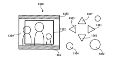
操作部136は、ユーザがスキャナ1を操作するための各種のキーを備えている。操作部136は、ほとんど全ての操作を方向指示キー1361、1363、1365、1367とOKキー1362とキャンセルキー1364によるメニュー操作で受け付ける。モード選択キー1366、1368、1369、1370が押下されると、それぞれのキーに応じたモードでスキャナ1が作動する。   The operation unit 136 includes various keys for the user to operate the scanner 1. The operation unit 136 accepts almost all operations through menu operations using the direction instruction keys 1361, 1363, 1365, 1367, the OK key 1362, and the cancel key 1364. When mode selection keys 1366, 1368, 1369, and 1370 are pressed, scanner 1 operates in a mode corresponding to each key.

表示部138は、ユーザがスキャナ1を操作するためのメニューを表示するための画面1380を備えている。画面1380はLCD等で構成される。
以上説明した操作部136及び表示部138は、制御部130と協働することにより請求項に記載の用紙設定手段として機能する。また、操作部136、表示部138及び制御部130は、請求項に記載の撮像制御装置の一例を構成している。
The display unit 138 includes a screen 1380 for displaying a menu for the user to operate the scanner 1. The screen 1380 is composed of an LCD or the like.
The operation unit 136 and the display unit 138 described above function as a sheet setting unit described in the claims by cooperating with the control unit 130. Further, the operation unit 136, the display unit 138, and the control unit 130 constitute an example of an imaging control device described in the claims.

図5は、制御プログラムを制御部130で実行しているスキャナ1の論理的な構成を示すブロック図である。
印刷設定部140は、表示部138の画面1380に印刷設定メニューを表示し、操作部136の出力信号に応じて、印刷用紙サイズと、印刷品質と、フチの有無とを特定する印刷設定情報を設定する。尚、印刷用紙サイズを変更する専用キーや印刷品質を変更する専用キーの押下によって、表示部138の画面1380を用いずに、印刷用紙サイズや印刷品質の設定操作を受け付けてもよい。また、印刷用紙サイズは、A3、A4、L版等の規格サイズを設定可能にしても良いし、ミリ単位又はインチ単位で設定可能にしても良い。
FIG. 5 is a block diagram showing a logical configuration of the scanner 1 that executes the control program in the control unit 130.
The print setting unit 140 displays a print setting menu on the screen 1380 of the display unit 138, and print setting information for specifying the print paper size, print quality, and presence / absence of a border according to the output signal of the operation unit 136. Set. Note that an operation for setting the print paper size and print quality may be accepted without using the screen 1380 of the display unit 138 by pressing a dedicated key for changing the print paper size or a dedicated key for changing the print quality. The print paper size may be set to a standard size such as A3, A4, or L plate, or may be set in units of millimeters or inches.

範囲変更部142は、読み取り範囲の変更を行う。読み取り範囲は、プレスキャン範囲内に設定可能なの矩形の領域である。また、範囲変更部142は、図8に示すように、プレスキャン画像1384と読み取り範囲に対応する第一矩形枠1382とを重ねて表示部138の画面1380に表示する。プレスキャン画像1384に対する第一矩形枠1382の位置及び大きさは、プレスキャン範囲に対する読み取り範囲の位置及び大きさと相似の関係にある。範囲変更部142は、操作部136の出力信号に応じて読み取り範囲の位置と大きさを変更し、第一矩形枠1382の位置と大きさを読み取り範囲に応じて変更する。この第一矩形枠1382は請求項に記載の「画面内領域を示すマーク」に相当する。範囲変更部142は、プレスキャン画像1384を拡大縮小せずにそのままの大きさで第一矩形枠とともに表示部138の画面1380に表示する。このとき、画面1380に表示されるプレスキャン画像1384は、予め決められたプレスキャン範囲に存在する対象物を表している。画面1380にハッチングを付して示した領域1385は、プレスキャン画像の外側領域である。尚、「画面内領域を示すマーク」は、矩形枠でなくても、例えば、読み取り範囲に対応した画面内領域の四隅を示す4つのマーク(十字形、L字形等)であってもよいし、画面内領域に一致する半透明の矩形であってもよい。また、画面内領域をフルカラーで表示し、画面内領域の外側の領域をモノクロで表示するなど、画面内領域の内外で階調表現や画質を変えることによって、読み取り範囲に対応した画面内領域を示してもよい。   The range changing unit 142 changes the reading range. The reading range is a rectangular area that can be set within the prescan range. In addition, as illustrated in FIG. 8, the range changing unit 142 displays the pre-scan image 1384 and the first rectangular frame 1382 corresponding to the reading range on the screen 1380 of the display unit 138 so as to overlap each other. The position and size of the first rectangular frame 1382 with respect to the pre-scan image 1384 are similar to the position and size of the reading range with respect to the pre-scan range. The range changing unit 142 changes the position and size of the reading range according to the output signal of the operation unit 136, and changes the position and size of the first rectangular frame 1382 according to the reading range. The first rectangular frame 1382 corresponds to a “mark indicating an in-screen area” described in the claims. The range changing unit 142 displays the pre-scan image 1384 on the screen 1380 of the display unit 138 together with the first rectangular frame with the same size without being enlarged or reduced. At this time, the prescan image 1384 displayed on the screen 1380 represents an object existing in a predetermined prescan range. A region 1385 indicated by hatching on the screen 1380 is an outer region of the pre-scan image. The “mark indicating the in-screen area” may not be a rectangular frame, but may be, for example, four marks (cross shape, L shape, etc.) indicating the four corners of the in-screen area corresponding to the reading range. A semi-transparent rectangle that matches the in-screen area may be used. In addition, by changing the gradation expression and image quality inside and outside the screen area, such as displaying the screen area in full color and displaying the area outside the screen area in monochrome, the screen area corresponding to the reading range can be changed. May be shown.

解像度設定部144は、印刷設定部140によって設定された印刷用紙サイズ及び印刷品質に応じて撮像部12の解像度を設定する。具体的には、印刷品質に応じて印刷解像度を変化させ、印刷範囲と印刷解像度との積算値であるスキャン画像のサイズと読み取り範囲のサイズとに応じて撮像部12の解像度を設定する。印刷品質が高いほど、また、印刷範囲が広いほど撮像部の解像度を上げ、逆に、印刷品質が低いほど、また、印刷範囲が狭いほど撮像部12の解像度を下げることにより、撮像部12は印刷設定に応じた適切な処理量でスキャン画像を生成することができる。なお、解像度設定部は、印刷品質、印刷用紙サイズのいずれか一方のみに応じて解像度を設定しても良いし、印刷品質及び印刷用紙サイズに加えてそれら以外の設定に応じても解像度を設定しても良い。   The resolution setting unit 144 sets the resolution of the imaging unit 12 according to the print paper size and print quality set by the print setting unit 140. Specifically, the print resolution is changed according to the print quality, and the resolution of the imaging unit 12 is set according to the size of the scanned image and the size of the read range, which is an integrated value of the print range and the print resolution. The higher the print quality and the wider the print range, the higher the resolution of the imaging unit. Conversely, the lower the print quality and the narrower the print range, the lower the resolution of the imaging unit 12. A scan image can be generated with an appropriate processing amount according to print settings. The resolution setting unit may set the resolution according to only one of the print quality and the print paper size, or set the resolution according to other settings in addition to the print quality and the print paper size. You may do it.

プレスキャン画像取得部146は、原稿ホルダ102によって決まるプレスキャン範囲を撮像部12に読み取らせることにより1又は2以上のプレスキャン画像を取得する。具体的には、原稿ホルダ102に35mmストリップフィルムがセットされている場合、プレスキャン画像取得部146は、原稿ホルダ102の種類を検出した後にフィルムの露光対象領域全体をプレスキャン範囲として設定し、プレスキャン範囲を比較的低解像度で撮像部12に読み取らせる。次に撮像部12に読みとらせて得た画像をプレスキャン画像取得部146が解析し、被写体が記録されているフレームの領域を全て抽出し、抽出したそれぞれの画像をプレスキャン画像とする。また、原稿ホルダ102に35mmマウントフィルムがセットされている場合、プレスキャン画像取得部146は原稿ホルダ102の種類を検出した後に原稿ホルダ102の複数の開口部に対応する複数のプレスキャン範囲をそれぞれ比較的低解像度で撮像部12に読み取らせ、撮像部12が読み取って得たそれぞれの画像をプレスキャン画像とする。   The prescan image acquisition unit 146 acquires one or more prescan images by causing the imaging unit 12 to read the prescan range determined by the document holder 102. Specifically, when a 35 mm strip film is set on the document holder 102, the prescan image acquisition unit 146 sets the entire exposure target area of the film as a prescan range after detecting the type of the document holder 102, The imaging unit 12 is caused to read the pre-scan range at a relatively low resolution. Next, the prescan image acquisition unit 146 analyzes the image obtained by reading the image pickup unit 12, extracts all the frame areas where the subject is recorded, and sets each extracted image as a prescan image. When a 35 mm mount film is set on the document holder 102, the prescan image acquisition unit 146 detects a plurality of prescan ranges corresponding to a plurality of openings of the document holder 102 after detecting the type of the document holder 102, respectively. The image capturing unit 12 reads the images at a relatively low resolution, and the images obtained by the image capturing unit 12 are used as prescan images.

読み取り範囲設定部148は、範囲変更部142において変更された読み取り範囲に応じて、読み取り範囲の再設定を行う。すなわち、範囲変更部142において設定された読み取り範囲内にプレスキャン画像の外側領域が含まれている場合は、プレスキャン画像の内側領域内に印刷用紙サイズのアスペクト比と同一アスペクト比で最大面積の矩形領域を読み取り範囲として再設定する。再設定する読み取り領域のアスペクト比は、印刷用紙サイズのアスペクト比と一致していなくても、印刷範囲のアスペクト比とほぼ同一であればよく、例えば左右上下のフチを除いた印刷範囲のアスペクト比と一致させてもよいし、四辺フチ無し印刷時に印刷用紙からはみ出すマージンを含めた印刷範囲のアスペクト比と一致させても良い。   The reading range setting unit 148 resets the reading range in accordance with the reading range changed by the range changing unit 142. That is, when the outer area of the pre-scan image is included in the reading range set by the range changing unit 142, the maximum area with the same aspect ratio as that of the print paper size is included in the inner area of the pre-scan image. Reset the rectangular area as the reading range. Even if the aspect ratio of the read area to be reset does not match the aspect ratio of the print paper size, it may be almost the same as the aspect ratio of the print range.For example, the aspect ratio of the print range excluding the left, right, top, and bottom edges Or the aspect ratio of the print range including the margin that protrudes from the printing paper during the four-sided borderless printing.

スキャン画像取得部150は、読み取り範囲設定部148によって設定された読み取り範囲を解像度設定部144によって設定された解像度で撮像部12に読み取らせ、スキャン画像を取得する。
印刷制御部152は、スキャン画像取得部150で取得したスキャン画像を、印刷設定部140によって設定された印刷条件でプリンタ2に印刷させる。具体的には、印刷制御部152は、印刷設定に基づいてスキャン画像にハーフトーン処理、インターレース処理等を施して印刷データを生成し、印刷設定に応じた印刷コマンドと印刷データとをプリンタ2に出力し、印刷設定に応じてプリンタ2にスキャン画像を印刷させる。
以上、スキャナ1の構成を説明した。以下、スキャナ1の作動を説明する。
The scanned image acquisition unit 150 causes the imaging unit 12 to read the reading range set by the reading range setting unit 148 with the resolution set by the resolution setting unit 144, and acquires a scanned image.
The print control unit 152 causes the printer 2 to print the scan image acquired by the scan image acquisition unit 150 under the print conditions set by the print setting unit 140. Specifically, the print control unit 152 generates print data by performing halftone processing, interlace processing, or the like on the scanned image based on the print settings, and sends a print command and print data corresponding to the print settings to the printer 2. The printer 2 outputs the scanned image according to the print setting.
The configuration of the scanner 1 has been described above. Hereinafter, the operation of the scanner 1 will be described.

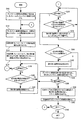
図1は、前述の制御プログラムによって作動するスキャナ1の作動を示すフローチャートである。図1に示すフローチャートは、原稿ホルダ102に35mmストリップフィルム又は35mmマウントフィルムがセットされている場合の処理の流れを示している。
ステップS10では、スキャナ1はプレスキャン範囲を低解像度で読み取り、各フレームのプレスキャン画像を生成する。具体的には、プレスキャン画像取得部146として機能している制御部130と撮像部12が協働することにより、1又は2フレーム以上のプレスキャン画像を生成する。プレスキャン画像を生成するとき、撮像部12の解像度は例えば100dpiに設定する。
FIG. 1 is a flowchart showing the operation of the scanner 1 operated by the control program described above. The flowchart shown in FIG. 1 shows the flow of processing when a 35 mm strip film or a 35 mm mount film is set on the document holder 102.
In step S10, the scanner 1 reads the prescan range at a low resolution and generates a prescan image of each frame. Specifically, the control unit 130 functioning as the prescan image acquisition unit 146 and the imaging unit 12 cooperate to generate a prescan image of one or more frames. When generating a pre-scan image, the resolution of the imaging unit 12 is set to, for example, 100 dpi.

ステップS12では、スキャナ1は各フレームのプレスキャン画像を画面表示し、印刷対象とするフレームの選択操作を受け付ける。具体的には、制御部130が表示部138の画面1380に例えば図6に示す画像選択メニューを表示し、方向指示キー1361、1363、1365、1367が押下されることによって操作部136から出力される信号に応じて制御部130が印刷対象のフレームを設定する。   In step S12, the scanner 1 displays a pre-scan image of each frame on the screen and accepts an operation for selecting a frame to be printed. Specifically, for example, the control unit 130 displays the image selection menu shown in FIG. 6 on the screen 1380 of the display unit 138, and the direction instruction keys 1361, 1363, 1365, and 1367 are pressed to output from the operation unit 136. In response to the signal, the control unit 130 sets a frame to be printed.

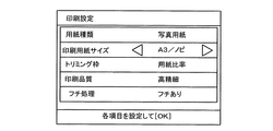
ステップS14では、スキャナ1は印刷対象フレームについて印刷設定操作を受け付ける。具体的には、印刷設定部140として機能している制御部130が表示部138の画面1380に例えば図7に示す印刷設定メニューを表示する。印刷設定メニューでは、方向指示キー1361、1363、1365、1367によって設定項目として、用紙種類と、印刷用紙サイズと、トリミング枠と、印刷品質と、フチ処理とを選択可能である。用紙種類は写真用紙、普通用紙等が選択可能に表示される。印刷用紙サイズはA3ノビ、A3、A4、ハガキ、L、2L等が選択可能に表示される。トリミング枠のアスペクト比の設定としては用紙比率又は任意比率が選択可能に表示される。印刷品質は高精細又は高速が選択可能に表示される。フチ処理の設定としてはフチあり又はフチ無しが選択可能に表示される。   In step S14, the scanner 1 accepts a print setting operation for the print target frame. Specifically, the control unit 130 functioning as the print setting unit 140 displays a print setting menu shown in FIG. 7 on the screen 1380 of the display unit 138, for example. In the print setting menu, a paper type, a print paper size, a trimming frame, print quality, and a border process can be selected as setting items using the direction instruction keys 1361, 1363, 1365, and 1367. The paper type is displayed so that photographic paper, plain paper, etc. can be selected. The print paper size is displayed such that A3 Nobi, A3, A4, postcard, L, 2L, etc. can be selected. As the setting of the aspect ratio of the trimming frame, a paper ratio or an arbitrary ratio is displayed so as to be selectable. The print quality is displayed so that high definition or high speed can be selected. As the setting of the border processing, bordered or borderless is displayed so as to be selectable.

ステップS16では、スキャナ1は、印刷対象フレームについて、読み取り範囲に対応する第一矩形枠1382とプレスキャン画像1384とを重ねて画面表示する。具体的には、範囲変更部142として機能している制御部130は、例えば図8に示すように、印刷対象フレームのプレスキャン画像1384と、第一矩形枠1382とを表示部138の画面1380に表示する。このとき制御部130は、プレスキャン画像1384の全体が画面1380に収まるようにプレスキャン画像1384を表示する。プレスキャン画像1384の外縁をユーザが視認できるように、プレスキャン画像1384の外側領域1385(ハッチングが付された領域)は例えば黒色などで表示する。また、読み取り範囲の大きさは、例えばプレスキャン範囲の70%の大きさとする。読み取り範囲の大きさがプレスキャン範囲より小さくなると、読み取り範囲はプレスキャン範囲内で移動可能になる。これにより、第一矩形枠1382もプレスキャン画像1384の70%の大きさで画面1380に表示される。   In step S <b> 16, the scanner 1 displays a screen on which the first rectangular frame 1382 corresponding to the reading range and the pre-scanned image 1384 are superimposed on the print target frame. Specifically, the control unit 130 functioning as the range changing unit 142 displays a pre-scan image 1384 of the frame to be printed and a first rectangular frame 1382, for example, as shown in FIG. To display. At this time, the control unit 130 displays the pre-scan image 1384 so that the entire pre-scan image 1384 fits on the screen 1380. The outer region 1385 (hatched region) of the pre-scan image 1384 is displayed in black or the like so that the user can visually recognize the outer edge of the pre-scan image 1384. Further, the size of the reading range is, for example, 70% of the pre-scanning range. When the size of the reading range becomes smaller than the pre-scanning range, the reading range can be moved within the pre-scanning range. As a result, the first rectangular frame 1382 is also displayed on the screen 1380 with a size of 70% of the pre-scan image 1384.

ステップS18では、スキャナ1は読み取り範囲の位置の確定操作が行われたか否かを判定し、確定操作が行われるとステップS24に進み、行われないとステップS20に進む。具体的には、範囲変更部142として機能している制御部130は、OKキー1362が押下されたか否かによって確定操作の有無を判定する。
ステップS20では、スキャナ1は、読み取り範囲の移動操作を受け付けたか判定し、移動操作を受け付けるとステップS22に進み、受け付けないとステップS18に進む。具体的には、範囲変更部142として機能している制御部130は、方向指示キー1361、1363、1365、1367が押下されたか否かによって移動操作の有無を判定する。
In step S18, the scanner 1 determines whether or not an operation for confirming the position of the reading range has been performed. If the confirmation operation has been performed, the process proceeds to step S24, and if not, the process proceeds to step S20. Specifically, the control unit 130 functioning as the range changing unit 142 determines the presence / absence of the confirmation operation based on whether or not the OK key 1362 is pressed.
In step S20, the scanner 1 determines whether or not an operation for moving the reading range has been received. If the moving operation is received, the process proceeds to step S22, and if not, the process proceeds to step S18. Specifically, the control unit 130 functioning as the range changing unit 142 determines the presence / absence of the moving operation based on whether or not the direction instruction keys 1361, 1363, 1365, and 1367 are pressed.

ステップS22では、スキャナ1は、読み取り範囲を移動させる。具体的には、範囲変更部142として機能している制御部130は、方向指示キー1361、1363、1365、1367が押下されることによって操作部136から出力される信号に応じて、読み取り範囲を移動させ、読み取り範囲の移動に応じて例えば図9に示すように第一矩形枠1382を画面1380上で平行移動させる。ステップS20及びステップS22は、読み取り範囲の位置の確定操作が行われるまで繰り返される。   In step S22, the scanner 1 moves the reading range. Specifically, the control unit 130 functioning as the range changing unit 142 sets the reading range in accordance with a signal output from the operation unit 136 when the direction instruction keys 1361, 1363, 1365, and 1367 are pressed. For example, as shown in FIG. 9, the first rectangular frame 1382 is translated on the screen 1380 in accordance with the movement of the reading range. Steps S20 and S22 are repeated until an operation for confirming the position of the reading range is performed.

ステップS24では、スキャナ1は、読み取り範囲の大きさの確定操作が行われたか否かを判定し、確定操作が行われるとステップS30に進み、行われないとステップS26に進む。具体的には、範囲変更部142として機能している制御部130は、OKキー1362が押下されたか否かによって大きさの確定操作の有無を判定する。
ステップS26では、スキャナ1は、読み取り範囲の大きさを変更する操作を受け付けたか判定し、受け付けるとステップS28に進み、受け付けないとステップS24に進む。具体的には、範囲変更部142として機能している制御部130は、方向指示キー1361、1363、1365、1367が押下されたか否かによって読み取り範囲の大きさを変更する操作の有無を判定する。
In step S24, the scanner 1 determines whether or not a confirmation operation for the size of the reading range has been performed. If the confirmation operation is performed, the process proceeds to step S30, and if not, the process proceeds to step S26. Specifically, the control unit 130 functioning as the range changing unit 142 determines the presence / absence of a size determining operation based on whether or not the OK key 1362 is pressed.
In step S26, the scanner 1 determines whether an operation for changing the size of the reading range has been accepted. If accepted, the process proceeds to step S28, and if not accepted, the process proceeds to step S24. Specifically, the control unit 130 functioning as the range changing unit 142 determines whether or not there is an operation for changing the size of the reading range depending on whether or not the direction instruction keys 1361, 1363, 1365, and 1367 are pressed. .

ステップS28では、スキャナ1は矩形の読み取り範囲の外縁の頂点の1つの位置を固定して、その頂点を含まない2辺をそれぞれの辺の垂線方向にそれぞれ移動させることにより読み取り範囲を変更し、読み取り範囲の変更に応じて第一矩形枠1382を変形する。具体的には例えば、図10に示すように、範囲変更部142として機能する制御部130は、右方向指示キー1361が押下されると、読み取り範囲の拡張に応じて第一矩形枠1382の右辺を右に移動させ、左方向指示キー1363が押下されると読み取り範囲の縮小に応じて第一矩形枠1382の右辺を左に移動させる。また、下方向指示キー1365が押下されると、読み取り範囲の拡張に応じて第一矩形枠1382の下辺を下方向に移動させ、上方向指示キー1367が押下されると第一矩形枠1382の下辺を上方向に移動させる。また、範囲変更部142は、第一矩形枠1382の右上角に方向指示キー1361、1363、1365、1367の操作によって動かない読み取り範囲の外縁の頂点を明示するための原点マーク1386を画面1380に表示してもよい。ステップS26及びステップS28は、読み取り範囲の大きさの確定操作が行われるまで繰り返される。   In step S28, the scanner 1 changes the reading range by fixing the position of one vertex of the outer edge of the rectangular reading range and moving the two sides not including the vertex in the normal direction of each side, The first rectangular frame 1382 is deformed according to the change of the reading range. Specifically, for example, as illustrated in FIG. 10, when the right direction instruction key 1361 is pressed, the control unit 130 functioning as the range changing unit 142 responds to the right side of the first rectangular frame 1382 according to the expansion of the reading range. When the left direction key 1363 is pressed, the right side of the first rectangular frame 1382 is moved to the left according to the reduction of the reading range. When the down direction key 1365 is pressed, the lower side of the first rectangular frame 1382 is moved downward according to the expansion of the reading range, and when the up direction key 1367 is pressed, the first rectangular frame 1382 is moved. Move the bottom side upward. The range changing unit 142 also displays an origin mark 1386 on the screen 1380 for clearly indicating the vertex of the outer edge of the reading range that does not move by operating the direction instruction keys 1361, 1363, 1365, 1367 in the upper right corner of the first rectangular frame 1382. It may be displayed. Steps S26 and S28 are repeated until an operation for confirming the size of the reading range is performed.

ステップS30では、読み取り範囲がプレスキャン範囲内であるかを判定する。具体的には、範囲変更部142として機能する制御部130がプレスキャン範囲の境界を特定し、読み取り範囲がプレスキャン範囲に入っていれば、ステップS30に進み、読み取り範囲がプレスキャン範囲の外側領域を含んでいれば、ステップS32に進む。
ステップS32では、読み取り範囲設定部148において、読み取り範囲の再設定を行う。具体的には、読み取り範囲とプレスキャン範囲の重複領域を算出し、重複領域内で印刷用紙のアスペクト比と同じアスペクト比で、重心が重複領域の重心と一致し、最大面積の矩形の領域を読み取り範囲として再設定する。この再設定された読み取り範囲は、請求項に記載の第二読み取り範囲に相当する。このとき、読み取り範囲設定部148として機能する制御部130は、再設定された読み取り範囲に対応する矩形枠を第二矩形枠1383として画面1380に表示してもよい。
In step S30, it is determined whether the reading range is within the pre-scanning range. Specifically, the control unit 130 functioning as the range changing unit 142 identifies the boundary of the prescan range, and if the read range is within the prescan range, the process proceeds to step S30, where the read range is outside the prescan range. If so, the process proceeds to step S32.
In step S32, the reading range setting unit 148 resets the reading range. Specifically, the overlapping area of the reading range and the pre-scanning area is calculated, and the centroid coincides with the centroid of the overlapping area with the same aspect ratio as that of the printing paper in the overlapping area, and the rectangular area having the maximum area is determined. Reset as reading range. The reset reading range corresponds to the second reading range described in the claims. At this time, the control unit 130 functioning as the reading range setting unit 148 may display a rectangular frame corresponding to the reset reading range on the screen 1380 as the second rectangular frame 1383.

ステップS34では、プレスキャン画像1384から読み取り範囲に設定された領域の画像を切り出し、切り出したスキャン画像1387を画面表示する。具体的には、範囲変更部142として機能している制御部130は、プレスキャン画像1384の読み取り範囲内の画像を切り出し、切り出したスキャン画像1387を、図11に示すように表示部138の画面内に拡大表示する。プレスキャン画像1384の読み取り範囲の画像を拡大表示することにより、ユーザは読み取り範囲を細かく設定可能になる。   In step S34, the image of the area set as the reading range is cut out from the pre-scan image 1384, and the cut-out scan image 1387 is displayed on the screen. Specifically, the control unit 130 functioning as the range changing unit 142 cuts out an image within the reading range of the pre-scan image 1384, and displays the cut-out scanned image 1387 on the screen of the display unit 138 as shown in FIG. Zoom in on the inside. By enlarging and displaying the image in the reading range of the pre-scan image 1384, the user can set the reading range in detail.

ステップS36では、スキャナ1は、読み取り範囲の位置及び大きさを完全に確定させる操作が行われたか否かを判定し、確定操作が行われるとステップS38に進み、行われないとステップS18に進んでさらに読み取り範囲の変更操作を続ける。具体的には、範囲変更部142として機能している制御部130は、OKキー1362が押下されたか否かによって完全な確定操作の有無を判定する。   In step S36, the scanner 1 determines whether or not an operation for completely confirming the position and size of the reading range has been performed. If the confirmation operation is performed, the process proceeds to step S38. If not, the process proceeds to step S18. Continue to change the reading range with. Specifically, the control unit 130 functioning as the range changing unit 142 determines the presence / absence of a complete confirmation operation based on whether or not the OK key 1362 is pressed.

ステップS38では、スキャナ1は、印刷用紙サイズ及び印刷品質に応じた解像度で、読み取り範囲を読み取り、スキャン画像を生成する。解像度設定部144は、読み取り範囲と、印刷品質と印刷用紙サイズとに応じてスキャン画像のサイズを特定し、スキャン画像のサイズと読み取り範囲に応じて解像度を設定する。結果的には、スキャン画像の対角線サイズがX、読み取り範囲の対角線サイズがY、プレスキャン画像の生成時の撮像部12の解像度が100dpiであるとすると、スキャン画像生成時の解像度は、100×X/Yである。スキャン画像取得部150は、読み取り範囲設定部148で設定された読み取り範囲を解像度設定部144で設定された解像度で撮像部12に読み取らせ、撮像部12からスキャン画像を出力させる。   In step S38, the scanner 1 reads the reading range at a resolution corresponding to the printing paper size and printing quality, and generates a scanned image. The resolution setting unit 144 specifies the size of the scanned image according to the reading range, the print quality, and the printing paper size, and sets the resolution according to the size of the scanned image and the reading range. As a result, assuming that the diagonal size of the scan image is X, the diagonal size of the reading range is Y, and the resolution of the imaging unit 12 when generating the pre-scan image is 100 dpi, the resolution when generating the scan image is 100 × X / Y. The scan image acquisition unit 150 causes the imaging unit 12 to read the reading range set by the reading range setting unit 148 with the resolution set by the resolution setting unit 144 and causes the imaging unit 12 to output a scan image.

ステップS40では、スキャナ1は、印刷設定に応じてプリンタ2にスキャン画像を印刷させる。具体的には、印刷制御部152は、スキャン画像にハーフトーン処理、インターレース処理等を施して印刷データを生成し、印刷設定に応じた印刷コマンドと印刷データをプリンタ2に出力する。プリンタ2は図12に示すように印刷コマンドと印刷データに応じてスキャン画像を印刷範囲52にインクを吹き付けて用紙50に画像を印刷する。図12(A)に示すように、「フチ有り」印刷の印刷範囲52は設定された余白分だけ用紙50より小さい。図12(B)に示すように、「フチ無し」印刷の印刷範囲52は設定されたはみ出し印刷幅だけ用紙50より若干大きい。   In step S40, the scanner 1 causes the printer 2 to print the scanned image according to the print setting. Specifically, the print control unit 152 generates print data by performing halftone processing, interlace processing, and the like on the scanned image, and outputs a print command and print data corresponding to the print setting to the printer 2. As shown in FIG. 12, the printer 2 prints an image on the paper 50 by spraying a scan image with ink on a print range 52 in accordance with a print command and print data. As shown in FIG. 12A, the print range 52 of the “bordered” print is smaller than the paper 50 by the set margin. As shown in FIG. 12B, the print range 52 of “borderless” printing is slightly larger than the paper 50 by the set overprint width.

ステップS42では、スキャナ1はユーザによって終了操作が行われたかを判定し、終了操作が行われない場合は、ステップS12に進み、上述の処理を繰り返す。
以上説明した本発明の実施例によると、スキャナ1は印刷用紙サイズに応じた適切な領域のスキャン画像を無駄なく取得することができる。すなわちスキャナ1は、切り出し処理せずにそのまま印刷できるサイズのスキャン画像を取得するため、スキャン画像の取得処理及び印刷処理に無駄がない。また、スキャナ1によると、印刷スキャン画像が画面に表示されるためユーザは印刷結果を予想することができる。また、読み取り範囲としてユーザが指定した領域にプレスキャン範囲の外側領域が含まれていると、自動的にプレスキャン範囲の外側領域を含まない領域を読み取り領域として再設定するので、プレスキャン範囲の外側領域を意識することなく読み取り領域を設定することができる。またスキャナ1は、印刷用紙サイズ応じて撮像部12の解像度を自動設定するため、印刷品質を高く維持しつつ、読み取りから印刷までの処理を高速化することができる。比較的小さな印刷用紙サイズが設定されている場合には、撮像部12の解像度を比較的低く設定しても印刷品質を高く維持することができるからである。
In step S42, the scanner 1 determines whether an end operation has been performed by the user. If the end operation has not been performed, the process proceeds to step S12 and the above-described processing is repeated.
According to the embodiment of the present invention described above, the scanner 1 can acquire a scan image of an appropriate area according to the printing paper size without waste. That is, since the scanner 1 acquires a scan image that can be printed as it is without being cut out, the scan image acquisition process and the print process are not wasted. Further, according to the scanner 1, since the print scan image is displayed on the screen, the user can predict the print result. Also, if the area specified by the user as the reading range includes an area outside the pre-scan range, the area that does not include the area outside the pre-scan range is automatically reset as the reading area. The reading area can be set without being aware of the outer area. In addition, since the scanner 1 automatically sets the resolution of the imaging unit 12 according to the print paper size, it is possible to speed up the processing from reading to printing while maintaining high print quality. This is because when a relatively small printing paper size is set, the print quality can be maintained high even if the resolution of the imaging unit 12 is set relatively low.

なお、上述した実施例では、請求項に記載した撮像制御装置がスキャナ1にある形態を説明したが、スキャナを制御するPCを撮像制御装置として本発明を実施することもできる。すなわち、スキャナ及びPCで撮像システムを構成し、PCでコピー機能を実現するための制御プログラム(本発明の撮像制御プログラムに相当する。)を実行し、PCの制御下でスキャナが原稿を読み取って得たスキャン画像をPCの制御下でプリンタが印刷してもよい。この場合、PCのマウス、ディスプレイ、キーボード等が請求項に記載の用紙設定手段及び範囲変更手段に相当することになる。
また、上述した実施例では、読み取り範囲に対応した第一矩形枠の変更操作を可能な形態を説明したが、変更操作不能な第一矩形枠を印刷用紙サイズに応じて設定してもよい。
In the above-described embodiment, the form in which the imaging control device described in the claims is provided in the scanner 1 has been described. However, the present invention can also be implemented using a PC that controls the scanner as the imaging control device. That is, the scanner and PC constitute an imaging system, a control program (corresponding to the imaging control program of the present invention) for realizing a copy function is executed by the PC, and the scanner reads the document under the control of the PC. The obtained scanned image may be printed by a printer under the control of the PC. In this case, the mouse, display, keyboard, etc. of the PC correspond to the sheet setting means and the range changing means described in the claims.
In the above-described embodiment, the mode in which the first rectangular frame corresponding to the reading range can be changed has been described. However, the first rectangular frame that cannot be changed may be set according to the print paper size.

本発明の一実施例によるスキャナの作動を示すフローチャート。3 is a flowchart showing the operation of a scanner according to an embodiment of the present invention. 本発明の一実施例によるスキャナの外観を示す斜視図。1 is a perspective view illustrating an appearance of a scanner according to an embodiment of the present invention. 本発明の一実施例によるスキャナの内部構造を示す模式図。1 is a schematic diagram showing an internal structure of a scanner according to an embodiment of the present invention. 本発明の一実施例によるスキャナを示すブロック図。1 is a block diagram showing a scanner according to an embodiment of the present invention. 本発明の一実施例による制御プログラムを示すブロック図。The block diagram which shows the control program by one Example of this invention. 本発明の一実施例に係る画面を示す図。The figure which shows the screen which concerns on one Example of this invention. 本発明の一実施例に係る画面を示す図。The figure which shows the screen which concerns on one Example of this invention. 本発明の一実施例に係る画面及び操作部を示す図。The figure which shows the screen and operation part which concern on one Example of this invention. 本発明の一実施例に係る画面及び操作部を示す図。The figure which shows the screen and operation part which concern on one Example of this invention. 本発明の一実施例に係る画面及び操作部を示す図。The figure which shows the screen and operation part which concern on one Example of this invention. 本発明の一実施例に係る画面及び操作部を示す図。The figure which shows the screen and operation part which concern on one Example of this invention. 本発明の一実施例に係る印刷結果を示す図。FIG. 6 is a diagram illustrating a printing result according to an embodiment of the present invention. 従来の画像処理システムの画面及び印刷結果を示す図。The figure which shows the screen and printing result of the conventional image processing system.

符号の説明Explanation of symbols

1 スキャナ(撮像システム)、2 プリンタ(印刷装置)、3 リムーバブルメモリ(外部記憶媒体)、12 撮像部、104 原稿、130 制御部(撮像制御装置)、134 メモリコントローラ(保存手段)、136 操作部(用紙設定手段)、138 表示部(用紙設定手段、読み取り範囲表示手段) DESCRIPTION OF SYMBOLS 1 Scanner (imaging system), 2 Printer (printing apparatus), 3 Removable memory (external storage medium), 12 Imaging part, 104 Original, 130 Control part (imaging control apparatus), 134 Memory controller (storage means), 136 Operation part (Paper setting means), 138 display unit (paper setting means, reading range display means)

Claims (7)

フィルム原稿を読み取る撮像システムの撮像部を制御するための撮像制御装置であって、
前記フィルム原稿の露光対象領域を第一読み取り範囲として設定する第一設定手段と、
アスペクト比が印刷用紙サイズのアスペクト比に対応する第二読み取り範囲を印刷用紙サイズの設定情報に基づいて前記第一読み取り範囲内に設定する第二設定手段と、
前記第二読み取り範囲を前記撮像部に読み取らせることによりスキャン画像を前記撮像部から出力させるスキャン制御手段と、
前記フィルム原稿の前記第一読み取り範囲を前記撮像部に読み取らせることによりプレスキャン画像を前記撮像部から出力させるプレスキャン制御手段と、
前記第二読み取り範囲を画面に表示する読み取り範囲表示手段と、を備え、
前記第一設定手段は、前記プレスキャン画像と、前記第一読み取り範囲に対応した画面内領域を示すマークと、を重ねて前記画面に表示し、
前記第二設定手段は、前記第二読み取り範囲が前記画面内領域の外側領域を含んでいる場合は、前記第二読み取り範囲の再設定を行う撮像制御装置。
An imaging control device for controlling an imaging unit of an imaging system that reads a film document ,
First setting means for setting the exposure target area of the film document as a first reading range;
Second setting means for setting a second reading range in which the aspect ratio corresponds to the aspect ratio of the printing paper size within the first reading range based on the setting information of the printing paper size;
Scan control means for outputting a scan image from the imaging unit by causing the imaging unit to read the second reading range;
Prescan control means for outputting a prescan image from the imaging unit by causing the imaging unit to read the first reading range of the film document;
Reading range display means for displaying the second reading range on the screen,
The first setting means displays the pre-scan image and a mark indicating an in-screen area corresponding to the first reading range on the screen in an overlapping manner,
The second control unit is an imaging control device that resets the second reading range when the second reading range includes an outer area of the in-screen area .
前記印刷用紙サイズの設定情報の設定操作を受け付ける用紙設定手段をさらに備える請求項1に記載の撮像制御装置。 The imaging control apparatus according to claim 1, further comprising a paper setting unit that receives a setting operation of setting information for the print paper size. 前記読み取り範囲表示手段は、前記スキャン画像の前記第二読み取り範囲に対応する領域を前記第一設定手段が前記プレスキャン画像を前記画面に表示する倍率よりも高い倍率で前記画面に表示する請求項1〜2のいずれか一項に記載の撮像制御装置。 The reading range display means, according to said region corresponding to said second reading range of the scanned image, wherein the first setting means is displayed on the screen at a higher magnification than the magnification for displaying the pre-scan image on the screen The imaging control device according to any one of Items 1 and 2 . 前記印刷用紙サイズの設定情報に応じた印刷用紙に前記スキャン画像を印刷装置で印刷させる印刷制御手段をさらに備える請求項1〜3のいずれか一項に記載の撮像制御装置。 The imaging control apparatus according to claim 1 , further comprising: a print control unit that causes the printing apparatus to print the scanned image on a printing sheet corresponding to the setting information of the printing sheet size. 前記印刷用紙サイズの設定情報に応じて前記撮像部の解像度を設定する解像度設定手段をさらに備える請求項1〜4のいずれか一項に記載の撮像制御装置。 The imaging control apparatus according to claim 1 , further comprising a resolution setting unit that sets a resolution of the imaging unit according to setting information of the print paper size. 請求項1〜5のいずれか一項に記載の前記撮像制御装置と、
前記撮像部と、
を備える撮像システム。
The imaging control device according to any one of claims 1 to 5 ,
The imaging unit;
An imaging system comprising:
前記スキャン画像を外部記憶媒体に保存する保存手段をさらに備える請求項6に記載の撮像システム。 The imaging system according to claim 6, further comprising storage means for storing the scanned image in an external storage medium.
JP2004205707A 2004-07-13 2004-07-13 Imaging control apparatus and imaging system Expired - Fee Related JP4367265B2 (en)

Priority Applications (1)

Application Number Priority Date Filing Date Title
JP2004205707A JP4367265B2 (en) 2004-07-13 2004-07-13 Imaging control apparatus and imaging system

Applications Claiming Priority (1)

Application Number Priority Date Filing Date Title
JP2004205707A JP4367265B2 (en) 2004-07-13 2004-07-13 Imaging control apparatus and imaging system

Publications (2)

Publication Number Publication Date
JP2006033136A JP2006033136A (en) 2006-02-02
JP4367265B2 true JP4367265B2 (en) 2009-11-18

Family

ID=35898998

Family Applications (1)

Application Number Title Priority Date Filing Date
JP2004205707A Expired - Fee Related JP4367265B2 (en) 2004-07-13 2004-07-13 Imaging control apparatus and imaging system

Country Status (1)

Country Link
JP (1) JP4367265B2 (en)

Families Citing this family (2)

* Cited by examiner, † Cited by third party
Publication number Priority date Publication date Assignee Title
JP2008116551A (en) * 2006-11-01 2008-05-22 Advanced Telecommunication Research Institute International Expression attaching voice generator
JP2008181450A (en) * 2007-01-26 2008-08-07 Fuji Xerox Co Ltd Image processing apparatus, image processing system, and image processing program

Also Published As

Publication number Publication date
JP2006033136A (en) 2006-02-02

Similar Documents

Publication Publication Date Title
US8208164B2 (en) Image processing apparatus and method
JP4570670B2 (en) Image processing apparatus, image reading apparatus, image forming apparatus, image processing method, image processing program, and recording medium
JP6421452B2 (en) Copier, computer program for copier, and method executed by copier
US11736641B2 (en) Apparatus and method for creating images from documents
JP4441558B2 (en) Image processing apparatus, image processing method, and program
JP4367265B2 (en) Imaging control apparatus and imaging system
JP2005354654A (en) Photographic image area extraction apparatus and copying machine
JP2003169177A (en) Image reader
JP2005341228A (en) Imaging control unit, imaging system, method for imaging control, and imaging control program
JP2018022950A (en) Image reading device and image reading method
US6608943B1 (en) Image processing method and apparatus
JP2005167934A (en) Image scanner
JPH09200445A (en) Image reader
JPH09200440A (en) Image reader
US20090046327A1 (en) Image Processing Device
JP2005333185A (en) Imaging system, imaging method, and imaging program
JP5029569B2 (en) Image reading apparatus, image reading method, and image reading program
JP4939016B2 (en) Image processing system and image processing method
JP2009194762A (en) Image processing apparatus
JPH10285334A (en) Image reader
JPH10327325A (en) Picture reader
JP3702692B2 (en) Print creation method and print creation apparatus
JP4623214B2 (en) Photo image area extraction device and copy device
JPH11103372A (en) Image reader
JP2004236000A (en) Original reader

Legal Events

Date Code Title Description
RD04 Notification of resignation of power of attorney

Free format text: JAPANESE INTERMEDIATE CODE: A7424

Effective date: 20060818

RD04 Notification of resignation of power of attorney

Free format text: JAPANESE INTERMEDIATE CODE: A7424

Effective date: 20061222

RD03 Notification of appointment of power of attorney

Free format text: JAPANESE INTERMEDIATE CODE: A7423

Effective date: 20061226

RD04 Notification of resignation of power of attorney

Free format text: JAPANESE INTERMEDIATE CODE: A7424

Effective date: 20070403

A621 Written request for application examination

Free format text: JAPANESE INTERMEDIATE CODE: A621

Effective date: 20070523

A977 Report on retrieval

Free format text: JAPANESE INTERMEDIATE CODE: A971007

Effective date: 20090421

A131 Notification of reasons for refusal

Free format text: JAPANESE INTERMEDIATE CODE: A131

Effective date: 20090512

A521 Written amendment

Free format text: JAPANESE INTERMEDIATE CODE: A523

Effective date: 20090710

TRDD Decision of grant or rejection written
A01 Written decision to grant a patent or to grant a registration (utility model)

Free format text: JAPANESE INTERMEDIATE CODE: A01

Effective date: 20090804

A01 Written decision to grant a patent or to grant a registration (utility model)

Free format text: JAPANESE INTERMEDIATE CODE: A01

A61 First payment of annual fees (during grant procedure)

Free format text: JAPANESE INTERMEDIATE CODE: A61

Effective date: 20090817

R150 Certificate of patent or registration of utility model

Free format text: JAPANESE INTERMEDIATE CODE: R150

FPAY Renewal fee payment (event date is renewal date of database)

Free format text: PAYMENT UNTIL: 20120904

Year of fee payment: 3

FPAY Renewal fee payment (event date is renewal date of database)

Free format text: PAYMENT UNTIL: 20130904

Year of fee payment: 4

LAPS Cancellation because of no payment of annual fees