JP4366155B2 - Bone densitometer for absolute fracture risk assessment - Google Patents
Bone densitometer for absolute fracture risk assessment Download PDFInfo
- Publication number
- JP4366155B2 JP4366155B2 JP2003325372A JP2003325372A JP4366155B2 JP 4366155 B2 JP4366155 B2 JP 4366155B2 JP 2003325372 A JP2003325372 A JP 2003325372A JP 2003325372 A JP2003325372 A JP 2003325372A JP 4366155 B2 JP4366155 B2 JP 4366155B2
- Authority
- JP
- Japan
- Prior art keywords
- patient
- risk
- fracture
- bone
- ray
- Prior art date
- Legal status (The legal status is an assumption and is not a legal conclusion. Google has not performed a legal analysis and makes no representation as to the accuracy of the status listed.)
- Expired - Lifetime
Links
- 206010017076 Fracture Diseases 0.000 title claims description 59
- 208000010392 Bone Fractures Diseases 0.000 title claims description 55
- 210000000988 bone and bone Anatomy 0.000 title claims description 25
- 238000012502 risk assessment Methods 0.000 title description 4
- 230000037182 bone density Effects 0.000 claims description 20
- 210000001624 hip Anatomy 0.000 claims description 9
- 210000004394 hip joint Anatomy 0.000 claims description 7
- 210000002436 femur neck Anatomy 0.000 claims description 6
- 210000000689 upper leg Anatomy 0.000 claims description 6
- 238000004364 calculation method Methods 0.000 claims description 4
- 229910052500 inorganic mineral Inorganic materials 0.000 claims description 4
- 239000011707 mineral Substances 0.000 claims description 4
- 230000004899 motility Effects 0.000 claims description 2
- 230000000391 smoking effect Effects 0.000 claims description 2
- 238000000326 densiometry Methods 0.000 claims 1
- 230000004048 modification Effects 0.000 claims 1
- 238000012986 modification Methods 0.000 claims 1
- 238000005259 measurement Methods 0.000 description 18
- 238000000034 method Methods 0.000 description 18
- 230000008569 process Effects 0.000 description 10
- 208000001132 Osteoporosis Diseases 0.000 description 7
- 206010020100 Hip fracture Diseases 0.000 description 4
- HVYWMOMLDIMFJA-DPAQBDIFSA-N cholesterol Chemical compound C1C=C2C[C@@H](O)CC[C@]2(C)[C@@H]2[C@@H]1[C@@H]1CC[C@H]([C@H](C)CCCC(C)C)[C@@]1(C)CC2 HVYWMOMLDIMFJA-DPAQBDIFSA-N 0.000 description 4
- 238000001739 density measurement Methods 0.000 description 4
- 208000029725 Metabolic bone disease Diseases 0.000 description 3
- 208000001164 Osteoporotic Fractures Diseases 0.000 description 3
- 238000002604 ultrasonography Methods 0.000 description 3
- 206010049088 Osteopenia Diseases 0.000 description 2
- 238000004891 communication Methods 0.000 description 2
- 230000001419 dependent effect Effects 0.000 description 2
- 230000036541 health Effects 0.000 description 2
- 238000013519 translation Methods 0.000 description 2
- 238000004458 analytical method Methods 0.000 description 1
- 239000008280 blood Substances 0.000 description 1
- 210000004369 blood Anatomy 0.000 description 1
- 235000012000 cholesterol Nutrition 0.000 description 1
- 208000029078 coronary artery disease Diseases 0.000 description 1
- 238000001514 detection method Methods 0.000 description 1
- 238000003745 diagnosis Methods 0.000 description 1
- 230000009977 dual effect Effects 0.000 description 1
- 238000011156 evaluation Methods 0.000 description 1
- 230000005021 gait Effects 0.000 description 1
- 230000000652 homosexual effect Effects 0.000 description 1
- 238000011835 investigation Methods 0.000 description 1
- 210000002414 leg Anatomy 0.000 description 1
- 150000002632 lipids Chemical class 0.000 description 1
- 210000004705 lumbosacral region Anatomy 0.000 description 1
- 238000000691 measurement method Methods 0.000 description 1
- 230000007246 mechanism Effects 0.000 description 1
- 238000010197 meta-analysis Methods 0.000 description 1
- 230000037230 mobility Effects 0.000 description 1
- 230000003562 morphometric effect Effects 0.000 description 1
- 238000013425 morphometry Methods 0.000 description 1
- 230000035764 nutrition Effects 0.000 description 1
- 235000016709 nutrition Nutrition 0.000 description 1
- 230000008520 organization Effects 0.000 description 1
- 238000003672 processing method Methods 0.000 description 1
- 230000009467 reduction Effects 0.000 description 1
- 238000000611 regression analysis Methods 0.000 description 1
- 210000004872 soft tissue Anatomy 0.000 description 1
- 206010041569 spinal fracture Diseases 0.000 description 1
Images


Classifications
-
- A—HUMAN NECESSITIES
- A61—MEDICAL OR VETERINARY SCIENCE; HYGIENE
- A61B—DIAGNOSIS; SURGERY; IDENTIFICATION
- A61B6/00—Apparatus for radiation diagnosis, e.g. combined with radiation therapy equipment
- A61B6/50—Clinical applications
- A61B6/505—Clinical applications involving diagnosis of bone
-
- A—HUMAN NECESSITIES
- A61—MEDICAL OR VETERINARY SCIENCE; HYGIENE
- A61B—DIAGNOSIS; SURGERY; IDENTIFICATION
- A61B6/00—Apparatus for radiation diagnosis, e.g. combined with radiation therapy equipment
- A61B6/48—Diagnostic techniques
- A61B6/482—Diagnostic techniques involving multiple energy imaging
-
- A—HUMAN NECESSITIES
- A61—MEDICAL OR VETERINARY SCIENCE; HYGIENE
- A61B—DIAGNOSIS; SURGERY; IDENTIFICATION
- A61B6/00—Apparatus for radiation diagnosis, e.g. combined with radiation therapy equipment
- A61B6/40—Apparatus for radiation diagnosis, e.g. combined with radiation therapy equipment with arrangements for generating radiation specially adapted for radiation diagnosis
- A61B6/4035—Apparatus for radiation diagnosis, e.g. combined with radiation therapy equipment with arrangements for generating radiation specially adapted for radiation diagnosis the source being combined with a filter or grating
-
- A—HUMAN NECESSITIES
- A61—MEDICAL OR VETERINARY SCIENCE; HYGIENE
- A61B—DIAGNOSIS; SURGERY; IDENTIFICATION
- A61B6/00—Apparatus for radiation diagnosis, e.g. combined with radiation therapy equipment
- A61B6/42—Apparatus for radiation diagnosis, e.g. combined with radiation therapy equipment with arrangements for detecting radiation specially adapted for radiation diagnosis
- A61B6/4208—Apparatus for radiation diagnosis, e.g. combined with radiation therapy equipment with arrangements for detecting radiation specially adapted for radiation diagnosis characterised by using a particular type of detector
- A61B6/4241—Apparatus for radiation diagnosis, e.g. combined with radiation therapy equipment with arrangements for detecting radiation specially adapted for radiation diagnosis characterised by using a particular type of detector using energy resolving detectors, e.g. photon counting
Description
本発明は、診断用医療装置に関し、具体的には、骨折の絶対リスクを示す出力を提供する骨密度測定装置に関する。 The present invention relates to a diagnostic medical device, and more particularly to a bone density measuring device that provides an output indicating an absolute risk of fracture.
骨密度測定装置は、典型的にはX線又は超音波測定を用いて、骨塩密度(bone mineral density)(BMD)の測定値を生成する。通常、このBMD値は、例えばg/cm2の面積密度測定値であるが、更に、例えば断層撮影再構成を用いて、例えばg/cm3の体積密度測定値を得ることもできる。 Bone densitometers typically produce bone mineral density (BMD) measurements using x-ray or ultrasound measurements. Usually, this BMD value is an area density measurement value of, for example, g / cm 2 , but a volume density measurement value of, for example, g / cm 3 can also be obtained by using, for example, tomographic reconstruction.
BMD測定は、身体の種々の部位で行うことができるが、腰椎椎骨、大腿骨頸部、又は足の踵骨の骨について行われることが最も多い。 BMD measurements can be made at various parts of the body, but are most often done on lumbar vertebrae, femoral neck, or ribs of the foot ribs.
X線及び超音波密度測定装置は、特に、米国特許第6438201号、第6364837号、第6277076号、第6246747号、第6215846号、第6160866号、第6081582号、第6038281号、第6027449号、再発行第36162号、第5841833号、第5840029号、及び第5748704号に記載されており、これらは、本発明の出願人に譲渡されており、本明細書において、参考文献として組み入れられる。 X-ray and ultrasonic density measuring devices are disclosed in particular in U.S. Pat. Reissue Nos. 36162, 5842833, 5840029, and 5748704, which are assigned to the assignee of the present invention and are hereby incorporated by reference.
生のBMD値は、医師又は患者にとって限定的な意味しかもたないため、現行の密度測定装置では、通常、測定したBMD値を確立された基準値と比較することが行われる。このような基準値の1つがTスコアであり、該Tスコアは、患者のBMD値を同性の若年成人についての予測BMD値と比較するものである。Tスコアは、該Tスコアの負の値が大きくなればなるほど、骨折のリスクが大きくなるという点で、骨折のリスクの定性的表示を与える。 Since the raw BMD value has only a limited meaning for the doctor or patient, current density measuring devices usually compare the measured BMD value with an established reference value. One such reference value is a T-score, which compares a patient's BMD value with a predicted BMD value for a homosexual young adult. The T score gives a qualitative indication of the risk of fracture, in that the greater the negative value of the T score, the greater the risk of fracture.
これに代えて、論理的回帰分析法を用いて、BMDの減少と骨折のリスクの増大との間の認知された数学的関係に基づき、BMDと相対骨折リスクとの間の定量的関係を求めることもできる。この関係は、高齢者母集団についての経験的検討で予測的に求められたものであり、患者と同年齢で同性の人物との間の差を考慮している。 Instead, a logical regression analysis method is used to determine a quantitative relationship between BMD and relative fracture risk based on a recognized mathematical relationship between BMD reduction and fracture risk increase. You can also. This relationship was obtained predictively in an empirical study of the elderly population, and takes into account the difference between patients and same-sex people.
骨密度測定装置は、患者の絶対骨折リスクを示すことになるのが望ましい。この点で、Tスコア及び相対リスク測定値は、不適切である。例えば、Tスコアが−2であり、相対リスクが4である70歳の高齢患者は、同じTスコア及び相対リスクである50歳の高齢患者より、絶対骨折リスクがはるかに高い。
本発明者らは、密度測定装置により生成されたBMD測定値が、単独では絶対骨折リスクを示すことができないことに気付いた。その反対に、現在の研究によると、絶対骨折リスクは、BMDに依存しない因子、特に年齢及び性別に強く依存していることを示している。絶対骨折リスクに影響を及ぼす他の因子には、患者が喫煙するかどうか、患者が行う運動量、患者の歩行量、患者の骨折の病歴、患者の家族の骨折の病歴、及び患者の股関節の縦軸線の長さ(股関節軸長さ)が含まれる。この他にも、リスク因子が見出されると考えられる。 The inventors have realized that BMD measurements generated by a density measuring device alone cannot indicate an absolute fracture risk. On the other hand, current studies show that absolute fracture risk is strongly dependent on factors that are not dependent on BMD, especially age and gender. Other factors that affect absolute fracture risk include whether the patient smokes, the amount of exercise performed by the patient, the patient's gait, the patient's fracture history, the patient's family fracture history, and the patient's hip length. The length of the axis (the hip joint axis length) is included. In addition to this, risk factors are considered to be found.
従って、本発明は、付加的な患者データを受け取り、絶対骨折リスクの出力測定値を生成する骨密度測定装置を提供する。医師及び患者に、この絶対骨折リスクが、BMDの測定と同時に提示されることにより、Tスコア及び相対リスクに関する患者の混乱を減少させ、医師による面倒な付加的な計算の必要性も排除する。 Accordingly, the present invention provides a bone density measuring device that receives additional patient data and generates an output measurement of absolute fracture risk. This absolute fracture risk is presented to the physician and patient at the same time as the BMD measurement, thereby reducing patient confusion regarding the T-score and relative risk and eliminating the need for cumbersome additional calculations by the physician.
さて、図1を参照すると、X線骨密度測定装置10は、縦軸線16に沿って患者を背臥位に支持するための水平な面を提供する患者テーブル12を含む。
Referring now to FIG. 1, the
C形腕18は、患者テーブル12の下に位置決めされてX線源20を支持する下部端と、患者テーブル12の上方に位置決めされて対向するX線検出器22を支持する上部端とを有することができる。X線源20は、その平面が、縦軸線16に平行である扇形ビーム24を生成し、好ましい実施形態では、X線源20は、2つのX線エネルギーを供給する。X線検出器22は、X線のエネルギーの間を識別する多要素CZT検出器とすることができる。また、当技術分野では公知なように、フィルタホイールを回転させるもの又はX線管電圧を変動させるものをはじめとする2重エネルギーを測定する他の方法を用いることもでき、同様に骨密度を測定するのに単一エネルギー技術を用いることもできる。
The C-shaped arm 18 has a lower end positioned below the patient table 12 to support the
X線源20及びX線検出器22は、患者の一連の横方向走査33をトレースするようにラスタパターン25で移動することができ、その間に、2重エネルギーX線のデータが、X線検出器22により收集される。ラスタパターン25は、扇形ビーム24の連続する走査線間で僅かに重なって、幾つかの高さデータが得られるように調節される。この走査の間に、X線源20、X線検出器22、及び平行移動制御装置19は、コンピュータ26と通信して該コンピュータ26の制御下に置かれており、このコンピュータ26は、専用回路及び/又は1つ又はそれ以上のプロセッサを含むことができる。コンピュータ26の動作は、以下に詳細に記載する内蔵プログラム部分の指示下にある。
The
コンピュータ26は、端末28と通信しており、該端末28は、後に説明するように、オペレータによる患者データの入力と、オペレータに走査の結果を与える文書及び/又は画像の出力とを可能にする表示装置30とキーボード31とマウス35のようなカーソル制御装置とを含む。
The
骨塩密度(BMD)データを取得するために骨密度測定装置10を操作する際には、コンピュータ26は、平行移動制御装置19と通信して、1回又はそれ以上の横方向走査33で患者の関心領域(37又は38)を走査することになる。各走査に沿って、2つの別個のX線エネルギーレベルでの減弱を測定した、扇形ビーム24の異なる光線に関連したデータが収集されることになる。異なるX線エネルギーについての2つの減弱測定値を組み合わせて、軟組織による減弱から実質的に独立した骨画像を生成することができる。
In operating the bone density measuring
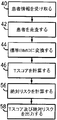
次に図4を参照すると、内蔵プログラムを図1のコンピュータ26で実行する最初の段階において、ブロック40で示すように、患者情報がコンピュータ26に入力される。この情報は、キーボード31、又はメニュー構造及びマウス35により入力することができ、更に別の患者記録システムからデータを送信することによっても入力することができる。
Referring now to FIG. 4, patient information is input to the
これらのデータは、一般的に、BMD以外の骨折のリスクに関する定量的情報を含み、典型的には、患者の年齢及び性別を含むことになる。しかしながら、本発明は更に、例えば患者の喫煙習慣(喫煙者又は非喫煙者)、患者が行う運動量、患者の運動性(例えば、日中徒歩で歩く時間、又は腕を使うことなく椅子から立ち上がることができるか否か、又は同様の尺度)、脆弱骨折に関する患者の病歴及び患者の家族の病歴、患者の椎骨に粉砕骨折があるかどうか、及び患者の股関節軸長さを含む付加的な患者情報を用いることも意図している。或いは、これらのうち最後の2つの数量は、以下に記載する走査工程により求め、医師の介入なしに入力されることもできる。 These data will generally include quantitative information regarding the risk of fractures other than BMD and will typically include the age and sex of the patient. However, the present invention further includes, for example, the patient's smoking habit (smoker or non-smoker), the amount of exercise performed by the patient, the patient's motility (eg, walking on the day, or standing up from a chair without using arms). Additional patient information including the patient's medical history of the vulnerable fracture and the patient's family history, whether the patient's vertebra has a fractured fracture, and the patient's hip axis length Is also intended to be used. Alternatively, the last two quantities of these can be determined by the scanning process described below and entered without physician intervention.
次の工程ブロック42でBMD以外の患者情報を入力した後、患者の走査を行い、骨画像を生成する。典型的には、図1に示すように、走査は、患者の股関節の周りの関心領域38、又は下部脊椎又は腰椎領域の部分の関心領域37のいずれかとされることになる。股関節の場合、関心領域38は、大腿骨頸部、転子、大腿骨骨幹部、ウォード領域、又は全大腿骨とすることができる。
In the
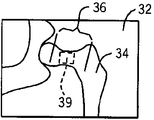
図2を参照すると、患者の大腿骨34の骨画像32の場合、患者の股関節軸長さ36の測定値が取り出され、上記のBMD以外の入力の1つとして用いられることができる。このような測定は、オペレータがカーソル制御装置35を用いて表示装置30の画像上にカーソルを位置決めすることにより行うことができ、或いはテンプレート構造等を用いて骨上に基準点を特定し、距離を数学的に計算する当技術分野で公知の自動又は半自動の処理方法により行うこともできる。
Referring to FIG. 2, in the case of a
同様のメカニズムを用いて、大腿骨34の頸部に測定領域39を位置決めし、BMD測定値を組み合わせて測定領域39全体にわたる平均骨密度を生成することになる区域を定めることができる。
A similar mechanism can be used to position the
工程ブロック44では、当技術分野で公知の技術により、測定領域39にわたる平均骨密度を標準BMD値に変換して、測定領域39の異なる定義及び異なる測定技術により生じる、異なる製造業者から入手した骨密度測定装置10間の差を補正する。
At
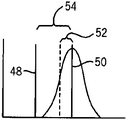
次に、工程ブロック46では、Tスコアを標準BMD値から計算する。図3を参照すると、このようなTスコアは、当技術分野では公知であり、処理過程44で補正されている、測定領域39内に見出される平均骨密度48を標準的個体の平均骨密度50と比較する。慣例により、標準的個体は、平均年齢30歳で患者と同性の個体の統計的組み合わせである。標準的個体に対する標準偏差は、標準を得るのに用いられた各個体の測定値から求めることができる。その時、Tスコアは、標準偏差52で割った間隔54で表される、平均骨密度48(患者の)と平均骨密度50(標準的個体の)との間の差である。
Next, at
オペレータに対しても出力することができるTスコアが工程ブロック56において計算された後、本発明では、絶対骨折リスクを計算する。絶対骨折リスクの計算値は、股関節骨折のリスク又は何らかの骨折のリスクとすることができ、これには、平均骨密度48(図3による)及び患者の年齢及び性別の情報(工程ブロック40よる)が用いられる。
After a T-score that can be output to the operator is calculated in
絶対骨折リスクを求める工程には、数種の公用データセットが用いられる。第1のデータセットからは、年齢で分類した各個体の規範的セットに対する平均BMD(又はその同等物)が得られる。このようなデータは、例えば、国民健康栄養試験調査(NHANES)(www.cdc.gov/nchs/nhanesを参照)のような政府委託の研究から入手可能である。この第1のデータセットは、これらの同一年齢分類の個体に対する骨折リスクを示す経験的に定められた第2のデータセットと組み合わされる。この結果が、各年齢群の平均絶対骨折リスク率である。 Several public data sets are used in the process of determining the absolute fracture risk. From the first data set, an average BMD (or equivalent) is obtained for the normative set for each individual classified by age. Such data is available, for example, from government commissioned studies such as the National Health and Nutrition Examination Survey (NHANES) (see www.cdc.gov/nchs/nhanes). This first data set is combined with an empirically determined second data set showing fracture risk for individuals of these same age classes. This result is the average absolute fracture risk rate of each age group.
第3のデータセットは、各年齢分類におけるBMDの所定の減少についての骨折の相対リスクを表す。この相対リスクは、患者のBMDと患者の年齢群に対する平均BMDと間の差に起因する相対リスクで、患者の年齢群に対する平均絶対骨折率を調整することにより患者の絶対リスクにされる。 The third data set represents the relative risk of fracture for a given decrease in BMD at each age category. This relative risk is the relative risk due to the difference between the patient's BMD and the average BMD for the patient's age group, and is made the patient's absolute risk by adjusting the average absolute fracture rate for the patient's age group.
従って、絶対骨折リスクは、個々の患者のBMD値の、患者の年齢群に対する正規のBMDからの偏差を求め、この年齢群に対する相対リスクをその年齢群の絶対骨折リスクに適用して個々の患者の絶対骨折リスクを求めることにより、個々の患者に対して計算することができる。 Therefore, the absolute fracture risk is calculated by calculating the deviation of the BMD value of an individual patient from the normal BMD for the patient's age group, and applying the relative risk for this age group to the absolute fracture risk of that age group. Can be calculated for individual patients by determining the absolute fracture risk.
これらの関係は、表の形式にした曲線の組に変換することができ、或いは当技術分野で公知の技術による明らかな等式に変換することもできる。これらのデータは、補間により滑らかにされ、連続関数を得ることができる。更に、絶対骨折の評価は、各国の相対骨折率に関する情報に基づき、種々の国に対して精度を高めることができる。付加的な調査を行うと、これらの等式又は曲線に付加的な因子を組み入れることができる。 These relationships can be converted into a set of curves in the form of a table, or can be converted into obvious equations according to techniques known in the art. These data are smoothed by interpolation, and a continuous function can be obtained. Furthermore, the evaluation of absolute fractures can improve accuracy for various countries based on information on the relative fracture rate of each country. Additional investigations can incorporate additional factors into these equations or curves.
基礎的データ及びこの方法論は、全体的に、以下の公的論文に記載されている。即ち、Marshallらの「骨塩密度の測定値により骨粗鬆による骨折の発生をどの程度予測できるかのメタ分析」Br.Med.J.312号1254〜1259頁(1996)、Kanisらの「相対リスクから求められる股関節骨折のリスク:スウェーデンの集団に行った分析」Osteoporosis Int.11号120〜127頁(2000)、Kanisらの「予測:骨粗鬆症の診断」J.Bone Miner.Res.第9巻第8号1137〜1141頁(1994)、Kanisらの「BMD及び診断閾値による骨粗鬆骨折の10年確率」J.Bone Miner.Res.16巻(補遺1)S194頁(2001)、De Laetらの「BMD及び診断閾値による骨粗鬆骨折の10年確率」J.Bone Miner.Res.第13巻第10号1587〜1593頁(2002)、Sirisらの「閉経後の女性における診断未確定の低骨塩密度の識別及び骨折の結果:全米骨粗鬆症リスク評価の結果」JAMA第286巻第22号2815〜2822頁(2001)である。 The basic data and this methodology are generally described in the following public papers: That is, Marshall et al., “A meta-analysis of the extent to which fractures due to osteoporosis can be predicted from the measured bone mineral density” Br. Med. J. et al. 312, pages 1254-1259 (1996), Kanis et al., “Risk of Hip Fractures Based on Relative Risk: Analysis Performed on Swedish Population” Osteoporosis Int. 11: 120-127 (2000), Kanis et al., “Prediction: Diagnosis of Osteoporosis” Bone Miner. Res. Vol. 9, No. 8, pp. 1137-1141 (1994), Kanis et al., “10-year probability of osteoporotic fractures by BMD and diagnostic threshold”. Bone Miner. Res. 16 (Appendix 1) S194 (2001), De Laet et al., “10-year probability of osteoporotic fractures with BMD and diagnostic threshold” Bone Miner. Res. Vol.13, No.10, pages 1587 to 1593 (2002), Siris et al., "Unidentified low bone mineral density identification and fracture results in postmenopausal women: Results of US osteoporosis risk assessment," JAMA Vol. 286, Vol. No. 22, pages 2815-2822 (2001).
これらの結果は、他の患者の入力変数との関係で知られているリスクに対する多数の乗数により修正することができる。例えば、股関節軸長さが6mm増大する(身長及び体重で調整した平均に比較して)毎に、換算係数1.6だけリスクが増大する。喫煙者の骨折に対するリスクは、非喫煙者に比較して1.3倍増大する。運動性の小さい(1日当たりの立っている時間が4時間より少ない)被検者又は腕を使うことなく椅子から立ち上がることができない被検者は、それぞれの場合で、骨折のリスクが2.0倍増大する。これら又は他の付加的なリスク因子が存在すると、絶対リスク評価は、BMD及び年齢モデルから求めたリスクに、科学文献に報告されている適切な相対危険係数を掛けることにより、更に正確にすることができる。 These results can be corrected by a number of multipliers for the risks known in relation to other patient input variables. For example, each time the hip joint axis length increases by 6 mm (compared to the average adjusted by height and weight), the risk increases by a conversion factor of 1.6. The risk for a smoker's fracture is 1.3 times greater than for a non-smoker. Subjects with low mobility (less than 4 hours of standing per day) or who cannot stand up from a chair without using their arms have a risk of fracture of 2.0 in each case. Doubles. In the presence of these or other additional risk factors, the absolute risk assessment should be made more accurate by multiplying the risk determined from the BMD and age model by the appropriate relative risk factor reported in the scientific literature. Can do.
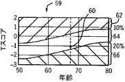
次の工程ブロック58では、絶対リスクの計算の結果が出力されることができる。図5を参照すると、グラフで示す出力において、患者の年齢を水平軸とすると、Tスコアは、グラフ59の垂直軸を形成する。工程ブロック46で計算された患者のTスコアは、患者の入力した年齢に対するプロット点60としてグラフ上にプロットされる。
In a
グラフの背景には、それぞれ低度、中度、及び高度の絶対骨折リスクを表す3つの異なる帯域62、64及び66を含む。一般的に、帯域62は低度絶対骨折リスク(好適には緑色が付される)を示し、帯域62の下方に位置する帯域64は中度絶対骨折リスク(好適には黄色が付される)を示し、また帯域62の下方に位置する帯域66は高度絶対骨折リスク(好適には赤色は付される)を示す。
The background of the graph includes three
帯域62と帯域64との間の境界線は、次の10年間における10%の骨折リスクを示し、帯域64と帯域66との間の境界線は、次の10年間における20%の骨折リスクを示す。この10%及び20%の閾値の選択は、米国コレステロール教育計画(NCEP)により定められたような成人の高度血中コレステロールの治療に用いる閾値に一致し、従って、医師には馴染み深いものである。しかしながら、骨折と骨密度との間の関係の強さは、脂質レベルと冠状動脈性心臓病との間の同様の関係より強い。
The boundary between
また、3つの帯域62、64、及び66をTスコアと位置合わせすることにより、母集団での骨粗鬆症の評価のために世界保健機構(WHO)により用意された区分にほぼ一致する患者の分類が得られる。従って、骨折リスクが著しく上昇する年齢65歳では、何らかの骨折に対する20%の10年リスクは、標準偏差が若年成人BMDより2.5又はそれ以上小さいBMDに基づくWHO分類の骨粗鬆症に一致する−2.5の大腿骨Tスコアにおいて発生する。同様に、年齢65歳での何らかの骨折に対する10%の10年リスクは、標準偏差が若年成人BMDより1と2.5との間だけ小さいBMDに基づくWHO分類の低骨質量(骨減少症)に一致する−1の大腿骨頸部Tスコアに等しい。従って、グラフの表示は、骨折リスク発生率が劇的に増大し始める年齢(65歳)でのWHOにより定められた正常、骨減少症、及び骨粗鬆症という公知の分類に一致している。しかしながら、WHO分類基準は、個体でなく母集団に対して定められたものであることを認識することが重要である。
Also, by aligning the three
帯域は、一般的に年齢と共に上昇し、任意のBMD値に対して、患者が高齢になるにつれリスクが増大することが反映されていることに留意されたい。このことは、任意の骨質量が高齢化しても一定のままである標準BMD及びTスコア値と比較されなければならない。帯域62、64及び66の特定の形状は、用いられる患者データに依存することになる。付加的なリスク因子を含む場合には、これらの帯域は、そのリスク因子によりシフトされる可能性がある。
Note that the band generally increases with age, reflecting that for any BMD value, the risk increases as the patient ages. This must be compared to standard BMD and T-score values that remain constant as any bone mass ages. The particular shape of the
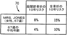
図6を参照すると、情報は更に、表の形式で与えられることができ、表70の第1の行では、第1の列に患者の氏名及び年齢、第2の列に股関節骨折の10年リスク、第3の列に何らかの骨折の10年リスクが示される。第2の行では、第1の列に患者と同年齢の基準母集団示す。第2の行の第2の列には、この母集団についての股関節骨折の10年リスクが示され、第3の列には、この母集団についての何らかの骨折の10年リスクが示される。 Referring to FIG. 6, information can further be provided in the form of a table, in the first row of table 70, the patient's name and age in the first column and the hip fracture in the second column for 10 years. Risk, the third column shows the 10-year risk of any fracture. In the second row, the first column shows a reference population of the same age as the patient. The second column of the second row shows the 10-year risk of hip fracture for this population, and the third column shows the 10-year risk of any fracture for this population.
次に図7を参照すると、図1の密度測定装置はまた、腰椎椎骨65の小柱領域に位置決めされた関心領域63からのBMDの測定に用いることができる。標準的形態計測技術を用いて、脆弱骨折を示すような破砕椎骨65’を検出することができ、該脆弱骨折は、絶対リスクの計算において上記の患者入力因子の1つとして用いることもできる。脆弱骨折が存在することは、将来の骨粗鬆症骨折の大きなリスク因子を示し、この脆弱骨折は、絶対リスクモデルに組み入れることができる。
Referring now to FIG. 7, the density measurement device of FIG. 1 can also be used to measure BMD from a region of
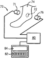
図8を参照すると、本発明は更に、超音波トランスデューサ71が患者の足74の踵骨72を通過する超音波信号を提供する超音波密度測定装置73に応用可能である。超音波信号は、検出器76で受信され、当技術分野で公知のように、コンピュータ80により処理されて音の速度(SOS)、又は超音波減衰(BUA)又はその2つの組み合わせが求められる。患者データは、付属のキーボード82を通して入力することができ、出力データは、当技術分野で公知の技術により出力表示装置に表示される。
Referring to FIG. 8, the present invention is further applicable to an ultrasonic
従って、本発明では、付加的な患者データを受け取ることにより、患者及び医師が望むような、相対リスクではなく絶対リスクの正確な測定を行う。絶対リスク評価は、真の骨折リスクが、若年個体では過大表示されるか又は高齢者では過小表示される場合があるTスコア又は相対リスク測定値よりも一層正確なリスクの表示である。 Thus, in the present invention, receiving additional patient data provides an accurate measure of absolute risk rather than relative risk as desired by patients and physicians. An absolute risk assessment is a more accurate representation of the risk of true fracture risk than a T-score or relative risk measure that may be over-represented in young individuals or under-represented in the elderly.
10 骨密度測定装置
12 患者テーブル
14 患者
16 縦軸線
18 C形腕
19 平行移動制御装置
20 X線源
22 X線検出器
24 扇形ビーム
25 ラスタパターン
26 コンピュータ
28 端末
30 表示装置
31 キーボード
32 骨画像
33 横方向走査
34 大腿骨
35 カーソル制御装置
35 マウス
36 股関節軸長さ
37 関心領域
38 関心領域(#37も参照)
39 測定領域
40 ブロック
42 ブロック(#40も参照)
44 ブロック(#42も参照)
46 ブロック(#46も参照)
48 平均骨密度
50 平均骨密度(#48も参照)
52 標準偏差
54 距離
56 ブロック(#46も参照)
58 ブロック(#56も参照)
59 グラフ
60 プロット点
63 関心領域
64 帯域(#97も参照)
65 腰椎椎骨
64 黄色を付けた帯域
66 帯域
70 テーブル
71 超音波トランスデューサ
72 踵骨
73 超音波密度測定装置
74 患者の足
76 検出器
80 コンピュータ(#26も参照)
82 付属のキーボード
84 出力表示装置
DESCRIPTION OF
39
44 blocks (see also # 42)
46 blocks (see also # 46)
48
52
58 blocks (see also # 56)
59
65
82 Attached
Claims (9)
エネルギー修正情報以外の患者情報(28)を受け取るための手段と、
前記信号及び前記患者情報を受信し、内蔵プログラム(40〜58)を実行するコンピュータ(26、80)と、
を含むコンピュータ化X線密度測定装置(10)、(73)であって、
該プログラムが、
(a)前記エネルギー源及び検出器を制御して、走査域にわたる複数の点に対するエネルギー修正信号を取得し、
(b)前記エネルギー修正信号に基づいて、前記患者の股関節を含む骨画像を生成し、
(c)前記骨画像を使用して前記患者の股関節軸長さ自動的に計算し、
(d)前記複数の点に対し、骨密度を計算し、
(e)前記骨密度及び自動的に計算した前記患者の股関節軸長さから、将来の予め定められた期間にわたる患者の骨折の絶対リスクを求め、
(f)前記骨折の絶対リスクを出力する、
ようになっていることを特徴とするコンピュータ化X線密度測定装置。 X-ray sources (20), (71) and detectors (22), (76) that can be face-to-face centered on the patient and generate a signal indicative of energy modification by the patient's bone;
Means for receiving patient information (28) other than energy correction information;
A computer (26, 80) for receiving the signal and the patient information and executing a built-in program (40-58);
A computerized X-ray density measuring device (10), (73) comprising:
The program is
(A) controlling the energy source and detector to obtain energy correction signals for a plurality of points across the scan area;
(B) generating a bone image including the patient's hip joint based on the energy correction signal;
(C) automatically calculating the hip axis length of the patient using the bone image;
( D ) calculating bone density for the plurality of points;
( E ) determining the absolute risk of patient fracture over a predetermined period in the future from the bone density and the automatically calculated hip axis length of the patient;
( F ) outputting the absolute risk of the fracture,
Computerized X-ray densitometry apparatus characterized that it is so.
前記線引きした帯域が、10%及び20%の骨折の絶対リスクを示すことを特徴とする、請求項4に記載の装置。 Every time the automatically calculated hip axis length increases by 6 mm compared to the average hip axis length adjusted by the patient's height and weight, the risk is increased by a conversion factor of 1.6,
The device according to claim 4 , characterized in that the delineated band shows an absolute risk of fracture of 10% and 20%.
前記コンピュータが前記表示装置(30)に前記骨画像を表示し、The computer displays the bone image on the display device (30);
前記股関節軸長さの自動的な計算が、オペレータがカーソル制御装置(35)を用いて前記表示装置(30)の画像上にカーソルを位置決めすることにより特定された基準点に基づいて行われる、請求項1乃至5のいずれかに記載の装置。The hip joint axis length is automatically calculated based on a reference point identified by an operator positioning the cursor on the image of the display device (30) using a cursor control device (35). The apparatus according to claim 1.
Applications Claiming Priority (1)
| Application Number | Priority Date | Filing Date | Title |
|---|---|---|---|
| US10/065,137 US6740041B2 (en) | 2002-09-19 | 2002-09-19 | Bone densitometer providing assessment of absolute fracture risk |
Publications (3)
| Publication Number | Publication Date |
|---|---|
| JP2004105738A JP2004105738A (en) | 2004-04-08 |
| JP2004105738A5 JP2004105738A5 (en) | 2008-11-20 |
| JP4366155B2 true JP4366155B2 (en) | 2009-11-18 |
Family
ID=31989985
Family Applications (1)
| Application Number | Title | Priority Date | Filing Date |
|---|---|---|---|
| JP2003325372A Expired - Lifetime JP4366155B2 (en) | 2002-09-19 | 2003-09-18 | Bone densitometer for absolute fracture risk assessment |
Country Status (2)
| Country | Link |
|---|---|
| US (1) | US6740041B2 (en) |
| JP (1) | JP4366155B2 (en) |
Families Citing this family (21)
| Publication number | Priority date | Publication date | Assignee | Title |
|---|---|---|---|---|
| WO2002071949A2 (en) * | 2001-02-28 | 2002-09-19 | Research Foundation Of State University Of New York | Method and apparatus for scanning confocal acoustic diagnostic for bone quality |
| US20050015002A1 (en) * | 2003-07-18 | 2005-01-20 | Dixon Gary S. | Integrated protocol for diagnosis, treatment, and prevention of bone mass degradation |
| US8202219B2 (en) * | 2004-02-23 | 2012-06-19 | Cyberlogic, Inc. | Ultrasonic bone assessment apparatus and method |
| US20060067471A1 (en) * | 2004-09-30 | 2006-03-30 | General Electric Company | Linear array detector system and inspection method |
| US7556045B1 (en) * | 2004-12-02 | 2009-07-07 | Chris Recknor, M.D. P.C. | System and method for osteoporosis assessment |
| US8419643B2 (en) * | 2006-09-21 | 2013-04-16 | Artann Laboratories Inc. | Ultrasonic method and apparatus for assessment of bone |
| US7804992B2 (en) * | 2006-10-02 | 2010-09-28 | Hologic, Inc. | Cardiovascular risk assessments using aortic calcification information derived from x-ray measurements taken with a dual energy x-ray densitometer |
| US7901356B2 (en) * | 2006-12-13 | 2011-03-08 | Cyberlogic, Inc. | Ultrasonic bone assessment apparatus and method |
| US9615814B2 (en) * | 2006-12-13 | 2017-04-11 | Cyberlogic, Inc. | Ultrasonic bone assessment apparatus and method |
| US7862510B2 (en) * | 2007-02-09 | 2011-01-04 | Cyberlogic, Inc. | Ultrasonic bone assessment apparatus and method |
| GB0806509D0 (en) * | 2008-04-10 | 2008-05-14 | Nordic Bioscience As | Vertebral fracture prediction |
| US8708561B2 (en) | 2009-03-20 | 2014-04-29 | Orthoscan, Inc. | Mobile imaging apparatus |
| WO2012082799A1 (en) | 2010-12-13 | 2012-06-21 | Orthoscan, Inc. | Mobile fluoroscopic imaging system |
| JP5599831B2 (en) * | 2012-02-09 | 2014-10-01 | 富士フイルム株式会社 | Method for identifying analysis target site in quantitative analysis of bone mineral, image processing apparatus and recording medium for implementing this method |
| KR101586276B1 (en) * | 2013-08-02 | 2016-01-18 | 서울대학교산학협력단 | Automated Mammographic Density Estimation and Display Method Using Prior Probability Information, System for the Method and Media Storing the Computer Program for the Method |
| US20150348259A1 (en) * | 2014-06-03 | 2015-12-03 | Carestream Health, Inc. | Quantitative method for 3-d bone mineral density visualization and monitoring |
| LT3371774T (en) * | 2015-11-05 | 2021-11-10 | Volpara Health Technologies Limited | Method for quantification of images |
| CN106510765B (en) * | 2016-11-30 | 2023-06-09 | 河北奥索电子科技有限公司 | Ultrasonic bone densitometer with full-dry calcaneal bone density ultrasonic probe |
| WO2018108849A1 (en) * | 2016-12-15 | 2018-06-21 | Koninklijke Philips N.V. | Ct imaging system and a method for a ct imaging system |
| WO2020166561A1 (en) | 2019-02-14 | 2020-08-20 | 富士フイルム株式会社 | Bone fracture risk evaluation value acquisition device, operation method therefor, and bone fracture risk evaluation value acquisition program |
| CN115279270A (en) * | 2020-03-13 | 2022-11-01 | 京瓷株式会社 | Prediction device, prediction system, control method, and control program |
Family Cites Families (10)
| Publication number | Priority date | Publication date | Assignee | Title |
|---|---|---|---|---|
| US4829549A (en) * | 1985-06-19 | 1989-05-09 | Vogel John M | Densitometer for scanning os calcis for predicting osteoporosis |
| US5840029A (en) * | 1988-05-11 | 1998-11-24 | Lunar Corporation | Imaging ultrasonic densitometer |
| US6027449A (en) * | 1988-05-11 | 2000-02-22 | Lunar Corporation | Ultrasonometer employing distensible membranes |
| US5509042A (en) * | 1991-02-13 | 1996-04-16 | Lunar Corporation | Automated determination and analysis of bone morphology |
| US6160866A (en) * | 1991-02-13 | 2000-12-12 | Lunar Corporation | Apparatus for bilateral femur measurement |
| US5228068A (en) * | 1992-09-14 | 1993-07-13 | Lunar Corporation | Device and method for automated determination and analysis of bone density and vertebral morphology |
| US6215846B1 (en) * | 1996-02-21 | 2001-04-10 | Lunar Corporation | Densitometry adapter for compact x-ray fluoroscopy machine |
| US6320931B1 (en) * | 1998-03-02 | 2001-11-20 | Image Analysis, Inc. | Automated x-ray bone densitometer |
| US6246745B1 (en) * | 1999-10-29 | 2001-06-12 | Compumed, Inc. | Method and apparatus for determining bone mineral density |
| US6385283B1 (en) * | 1999-11-24 | 2002-05-07 | Hologic, Inc. | Device and method for determining future fracture risk |
-
2002
- 2002-09-19 US US10/065,137 patent/US6740041B2/en not_active Expired - Lifetime
-
2003
- 2003-09-18 JP JP2003325372A patent/JP4366155B2/en not_active Expired - Lifetime
Also Published As
| Publication number | Publication date |
|---|---|
| US20040059223A1 (en) | 2004-03-25 |
| JP2004105738A (en) | 2004-04-08 |
| US6740041B2 (en) | 2004-05-25 |
Similar Documents
| Publication | Publication Date | Title |
|---|---|---|
| JP4366155B2 (en) | Bone densitometer for absolute fracture risk assessment | |
| Laib et al. | Ridge number density: a new parameter for in vivo bone structure analysis | |
| US7801347B2 (en) | Assessing cardiovascular and vertebral/hip fracture risk and bone condition using quantitative computed tomography and/or dual energy x-ray absorptiometry | |
| Pisani et al. | Screening and early diagnosis of osteoporosis through X-ray and ultrasound based techniques | |
| Brunader et al. | Radiologic bone assessment in the evaluation of osteoporosis | |
| US5577089A (en) | Device and method for analysis of bone morphology | |
| US8483458B2 (en) | Method and system for measuring visceral fat mass using dual energy x-ray absorptiometry | |
| JP2719444B2 (en) | Method and apparatus for automatically determining and analyzing bone morphology | |
| JP4814468B2 (en) | Apparatus and method for determining future fracture risk | |
| KR101928984B1 (en) | Method and apparatus of bone mineral density measurement | |
| KR101900122B1 (en) | Ultrasound apparatus for assessing the quality of a patient’s bone tissue | |
| US8300911B1 (en) | Methods and apparatus for measuring visceral fat mass | |
| US8295570B2 (en) | Methods and apparatus for measuring body circumference | |
| US7387439B2 (en) | X-ray beam calibration for bone mineral density assessment using mammography system | |
| KR100419573B1 (en) | Method for evaluating trabecular bone using X-ray image | |
| Ma et al. | Comparison of the spine and hip BMD assessments derived from quantitative computed tomography | |
| Faulkner | Clinical use of bone densitometry | |
| Damilakis et al. | Effect of region of interest location on ultrasound measurements of the calcaneus | |
| KR20210054925A (en) | System and Method for Extracting Region of Interest for Bone Mineral Density Calculation | |
| Sarvazyan et al. | Application of the dual-frequency ultrasonometer for osteoporosis detection | |
| Edmondston et al. | The relationship between bone mineral density, vertebral body shape and spinal curvature in the elderly thoracolumbar spine: an in vitro study | |
| US10089728B2 (en) | Radiation-image processing device and method | |
| Maricic et al. | Bone densitometry | |
| Berry | DXA scanning of the lumbar spine and proximal femur | |
| Damilakis et al. | Broadband ultrasound attenuation imaging: algorithm development and clinical assessment of a region growing technique |
Legal Events
| Date | Code | Title | Description |
|---|---|---|---|
| A621 | Written request for application examination |
Free format text: JAPANESE INTERMEDIATE CODE: A621 Effective date: 20060913 |
|
| A521 | Request for written amendment filed |
Free format text: JAPANESE INTERMEDIATE CODE: A523 Effective date: 20081006 |
|
| A131 | Notification of reasons for refusal |
Free format text: JAPANESE INTERMEDIATE CODE: A131 Effective date: 20090414 |
|
| A521 | Request for written amendment filed |
Free format text: JAPANESE INTERMEDIATE CODE: A523 Effective date: 20090710 |
|
| RD02 | Notification of acceptance of power of attorney |
Free format text: JAPANESE INTERMEDIATE CODE: A7422 Effective date: 20090710 |
|
| RD04 | Notification of resignation of power of attorney |
Free format text: JAPANESE INTERMEDIATE CODE: A7424 Effective date: 20090710 |
|
| TRDD | Decision of grant or rejection written | ||
| A01 | Written decision to grant a patent or to grant a registration (utility model) |
Free format text: JAPANESE INTERMEDIATE CODE: A01 Effective date: 20090804 |
|
| A01 | Written decision to grant a patent or to grant a registration (utility model) |
Free format text: JAPANESE INTERMEDIATE CODE: A01 |
|
| A61 | First payment of annual fees (during grant procedure) |
Free format text: JAPANESE INTERMEDIATE CODE: A61 Effective date: 20090824 |
|
| FPAY | Renewal fee payment (event date is renewal date of database) |
Free format text: PAYMENT UNTIL: 20120828 Year of fee payment: 3 |
|
| R150 | Certificate of patent or registration of utility model |
Free format text: JAPANESE INTERMEDIATE CODE: R150 Ref document number: 4366155 Country of ref document: JP Free format text: JAPANESE INTERMEDIATE CODE: R150 |
|
| FPAY | Renewal fee payment (event date is renewal date of database) |
Free format text: PAYMENT UNTIL: 20120828 Year of fee payment: 3 |
|
| FPAY | Renewal fee payment (event date is renewal date of database) |
Free format text: PAYMENT UNTIL: 20130828 Year of fee payment: 4 |
|
| R250 | Receipt of annual fees |
Free format text: JAPANESE INTERMEDIATE CODE: R250 |
|
| R250 | Receipt of annual fees |
Free format text: JAPANESE INTERMEDIATE CODE: R250 |
|
| R250 | Receipt of annual fees |
Free format text: JAPANESE INTERMEDIATE CODE: R250 |
|
| R250 | Receipt of annual fees |
Free format text: JAPANESE INTERMEDIATE CODE: R250 |
|
| R250 | Receipt of annual fees |
Free format text: JAPANESE INTERMEDIATE CODE: R250 |
|
| R250 | Receipt of annual fees |
Free format text: JAPANESE INTERMEDIATE CODE: R250 |
|
| R250 | Receipt of annual fees |
Free format text: JAPANESE INTERMEDIATE CODE: R250 |
|
| R250 | Receipt of annual fees |
Free format text: JAPANESE INTERMEDIATE CODE: R250 |
|
| R250 | Receipt of annual fees |
Free format text: JAPANESE INTERMEDIATE CODE: R250 |
|
| R250 | Receipt of annual fees |
Free format text: JAPANESE INTERMEDIATE CODE: R250 |
|
| R250 | Receipt of annual fees |
Free format text: JAPANESE INTERMEDIATE CODE: R250 |
|
| R250 | Receipt of annual fees |
Free format text: JAPANESE INTERMEDIATE CODE: R250 |
|
| EXPY | Cancellation because of completion of term |