JP4366147B2 - Scanning optical system and printer - Google Patents
Scanning optical system and printer Download PDFInfo
- Publication number
- JP4366147B2 JP4366147B2 JP2003308329A JP2003308329A JP4366147B2 JP 4366147 B2 JP4366147 B2 JP 4366147B2 JP 2003308329 A JP2003308329 A JP 2003308329A JP 2003308329 A JP2003308329 A JP 2003308329A JP 4366147 B2 JP4366147 B2 JP 4366147B2
- Authority
- JP
- Japan
- Prior art keywords
- region
- optical system
- light beam
- central region
- phase difference
- Prior art date
- Legal status (The legal status is an assumption and is not a legal conclusion. Google has not performed a legal analysis and makes no representation as to the accuracy of the status listed.)
- Expired - Fee Related
Links
- 230000003287 optical effect Effects 0.000 title claims description 103
- 238000003384 imaging method Methods 0.000 claims description 13
- 230000014509 gene expression Effects 0.000 claims description 12
- 230000010363 phase shift Effects 0.000 description 71
- 238000010586 diagram Methods 0.000 description 12
- 230000004907 flux Effects 0.000 description 9
- 230000005540 biological transmission Effects 0.000 description 5
- 230000007423 decrease Effects 0.000 description 5
- 239000011248 coating agent Substances 0.000 description 2
- 238000000576 coating method Methods 0.000 description 2
- 230000002093 peripheral effect Effects 0.000 description 2
- 239000012466 permeate Substances 0.000 description 2
- 230000003247 decreasing effect Effects 0.000 description 1
- 230000007547 defect Effects 0.000 description 1
- 230000000694 effects Effects 0.000 description 1
- 238000005530 etching Methods 0.000 description 1
- 229910052736 halogen Inorganic materials 0.000 description 1
- 150000002367 halogens Chemical class 0.000 description 1
- 238000004519 manufacturing process Methods 0.000 description 1
- 239000000463 material Substances 0.000 description 1
- 238000000465 moulding Methods 0.000 description 1
- 238000007740 vapor deposition Methods 0.000 description 1
Images

Landscapes
- Laser Beam Printer (AREA)
- Mechanical Optical Scanning Systems (AREA)
- Facsimile Scanning Arrangements (AREA)
Description
本発明は、感光ドラムの表面に静電潜像を形成するための走査光学系と、このような走査光学系が内部に組み込まれたプリンターとに、関する。 The present invention relates to a scanning optical system for forming an electrostatic latent image on the surface of a photosensitive drum, and a printer in which such a scanning optical system is incorporated.
周知のように、レーザービームプリンターやファクシミリやコピー機などの印刷装置には、走査光学系が組み込まれている。走査光学系は、画像情報に従って変調されたレーザービームを回転多面鏡によって動的に偏向するとともに、動的に偏向されたレーザービームを結像光学系によって感光ドラムの表面上に収束させることにより、感光ドラムを走査する。走査された感光ドラムの表面(走査対象面)には、複数のドットが静電潜像として描画される。 As is well known, a scanning optical system is incorporated in a printing apparatus such as a laser beam printer, a facsimile machine, or a copier. The scanning optical system dynamically deflects the laser beam modulated according to the image information by the rotating polygon mirror, and converges the dynamically deflected laser beam on the surface of the photosensitive drum by the imaging optical system, Scan the photosensitive drum. A plurality of dots are drawn as an electrostatic latent image on the surface of the scanned photosensitive drum (surface to be scanned).
一般に、走査対象面に入射するレーザービームの強度分布は、完全なガウス分布とはなっておらず、レーザービームの光路中に設けられた開口(アパーチャー)での回折現象により、メインビームの周囲にメインビームより光量の低い幾つかの光の輪(サイドローブ)を有していることが、知られている。また、このサイドローブの強度が、メインビームの中心強度の約6%を超えると、サイドローブが感光ドラムを感光させて、黒スジと呼ばれる印字不良をハーフトーン印字時に発生させることも、知られている(特許文献1参照)。但し、結像光学系が理想的な状態では、サイドローブの強度は、メインビームの中心強度の4%程度であるため、黒スジは発生しない。
ところが、結像光学系の光学面に微視的なうねりがあると、うねりの部分をレーザービームが通過した際に、サイドローブの強度が変化する。その変化によってサイドローブの強度が閾値を超えてしまうと、ハーフトーン印字時に黒スジが発生するという問題があった。 However, if the optical surface of the imaging optical system has microscopic undulations, the intensity of the side lobe changes when the laser beam passes through the undulations. If the intensity of the side lobe exceeds the threshold due to the change, there is a problem that black streaks occur during halftone printing.
そこで、本発明の課題は、結像光学系の光学面に或る程度の微視的なうねりが生じている場合でも、サイドローブの強度が閾値を超えることをできるだけ抑制することができる走査光学系と、このような走査光学系が内部に組み込まれたプリンターとを、提供することにある。 Accordingly, an object of the present invention is to provide a scanning optical that can suppress the side lobe intensity from exceeding a threshold value as much as possible even when a certain degree of microscopic undulation occurs on the optical surface of the imaging optical system. It is to provide a system and a printer in which such a scanning optical system is incorporated.
上記の課題を解決するために、本発明による走査光学系,及び、本発明によるプリンターの内部に組み込まれた走査光学系は、以下のような構成を採用した。 In order to solve the above problems, the scanning optical system according to the present invention and the scanning optical system incorporated in the printer according to the present invention employ the following configurations.
すなわち、この走査光学系は、光源から発せられた平行なレーザービームを偏向器によ
って動的に偏向するとともに、動的に偏向されたレーザービームを結像光学系によって走査対象面上にスポット光として収束させることにより、前記スポット光を前記走査対象面上で主走査方向に沿って走査させる走査光学系であって、前記光源と前記偏向器との間の光路上に、光学素子を備え、前記光学素子は、前記光源から発せられる平行なレーザービームのうちのビーム中心軸及びその近傍の光束を透過させる中央領域と、前記中央領域の外側に入射する光束の一部を透過させるとともに透過後の光束が前記中央領域を透過した光束に対して所定の第1の位相差を付与するように作用する第1外側領域と、前記中央領域及び前記第1外側領域に入射する光束を除く光束の一部を透過させるとともに透過後の光束が前記中央領域を透過した光束に対して所定の第2の位相差を付与するように作用する第2外側領域とを有し、前記各外側領域は、前記中央領域から前記主走査方向における両側に向かって順に、配置されており、前記第1の位相差は、整数をNとしたとき、(2N−1)π[rad]であるとともに、前記第2の位相差は、整数をMとしたとき、2Mπ[rad]であることを、特徴としている。
That is, this scanning optical system dynamically deflects a parallel laser beam emitted from a light source by a deflector and uses the dynamically deflected laser beam as spot light on a scanning target surface by an imaging optical system. A scanning optical system that scans the spot light along the main scanning direction on the surface to be scanned by converging, and includes an optical element on an optical path between the light source and the deflector, The optical element transmits a part of the light beam incident on the outside of the central region and a central region that transmits the light beam in the vicinity of the beam central axis of the parallel laser beams emitted from the light source, and after transmission. a first outer region which acts to impart a first phase difference given to the light flux which the light beam transmitted through the central region, incident on the central region and the first outer region And a second outer region which acts to apply a predetermined second phase difference to the light flux which the light beam after transmission is transmitted through the central region, and to reflect a portion of light flux except for the light beam that, The outer regions are sequentially arranged from the central region toward both sides in the main scanning direction, and the first phase difference is (2N−1) π [rad] where N is an integer. And the second phase difference is 2Mπ [rad] where M is an integer .
このように構成されると、第1及び第2外側領域をそれぞれ透過した後の光束の第1及び第2の位相差状態が、適宜設定され、且つ、第1及び第2外側領域の大きさが、適宜選択されていれば、走査対象面に入射するレーザービームのサイドローブの強度を、メインビームの中心強度の2%弱にまで抑えることができる。従って、サイドローブの強度が、結像光学系の光学面の微視的なうねりに因って数%程度上昇したとしても、閾値を超えることがない。その結果、ハーフトーン印字時の黒スジの発生が抑えられる。 If comprised in this way, the 1st and 2nd phase difference state of the light beam after each passing 1st and 2nd outer area | region will be set suitably, and the magnitude | size of the 1st and 2nd outer area | region will be set. However, if appropriately selected, the intensity of the side lobe of the laser beam incident on the scanning target surface can be suppressed to less than 2% of the center intensity of the main beam. Therefore, even if the intensity of the side lobe increases by about several percent due to the microscopic undulation of the optical surface of the imaging optical system, the threshold value is not exceeded. As a result, the occurrence of black streaks during halftone printing is suppressed.
なお、本発明による走査光学系及びプリンターでは、光学素子は、中央領域から外側に向かって順に第1及び第2外側領域を有していても良い。 In the scanning optical system and printer according to the present invention, the optical element may have first and second outer regions in order from the central region to the outer side.
また、本発明による走査光学系及びプリンターでは、第1外側領域が、自身を透過するレーザービームに対し、以下の条件式(1)、
cosθ≦0 ---(1)
を満たす位相差θ[rad]を付与することが好ましく、整数をNとしたとき、その位相差θがπ×(2N−1)[rad]に近くなるほど、サイドローブ低減の効果がある。
In the scanning optical system and the printer according to the present invention, the first outer region has the following conditional expression (1) with respect to the laser beam transmitted therethrough,
cosθ ≦ 0 --- (1)
It is preferable to give a phase difference θ [rad] satisfying the above. When the integer is N, the sidelobe reduction is more effective as the phase difference θ becomes closer to π × (2N−1) [rad].
また、本発明による走査光学系及びプリンターでは、第2外側領域が、自身を透過するレーザービームに対し、以下の条件式(2)、
0.9≦cosθ’ ---(2)
を満たす位相差θ’[rad]を付与することが好ましく、エネルギーの利用効率および製造時の加工容易性の観点からすると、整数をMとしたとき、その位相差θ'が2π×M[rad]であることが望ましい。
In the scanning optical system and the printer according to the present invention, the second outer region has the following conditional expression (2) with respect to the laser beam transmitted therethrough,
0.9 ≦ cosθ '--- (2)
It is preferable to provide a phase difference θ ′ [rad] satisfying the above. From the viewpoint of energy use efficiency and ease of processing during manufacturing, when the integer is M, the phase difference θ ′ is 2π × M [rad]. ] Is desirable.
また、本発明による走査光学系及びプリンターでは、光学素子は、第1及び第2外側領域を1組備えていても良いし、複数組備えていても良い。複数組備えている場合には、各第1及び第2外側領域を、中央領域から離れる方向に向かって交互に配置することができる。さらに、交互に配置する場合においては、第2外側領域が最も外側に配置されることが望ましい。 In the scanning optical system and the printer according to the present invention, the optical element may include one set of the first and second outer regions or a plurality of sets. When a plurality of sets are provided, the first and second outer regions can be alternately arranged in the direction away from the central region. Furthermore, in the case of arranging alternately, it is desirable that the second outer region is arranged on the outermost side.
ところで、各第1外側領域が、条件式(1)を満たす位相差をレーザービームに対して付与するとともに、各第2外側領域が、条件式(2)を満たす位相差をレーザービームに対して付与する場合、第1外側領域の面積の総和は、適切に設定されることが望ましい。例えば、第1外側領域のうちのレーザービームが入射する領域の面積の総和をS’とし、レーザービームにおけるビーム中心軸に直交する断面の面積をSとしたとき、以下の条件式(3)、
0.03<S’/S<0.3 ---(3)
を満足するように、設定することができる。なお、このような設定条件において、下限を下回るとサイドローブを低減させる効果が小さくなり、逆に、上限を上回るとサイドローブを効果的に低減できるものの、メインビームの中心強度の減少量が大きくなる。
By the way, each first outer region gives a phase difference satisfying conditional expression (1) to the laser beam, and each second outer region gives a phase difference satisfying conditional expression (2) to the laser beam. In the case of providing, it is desirable that the total area of the first outer region is set appropriately. For example, when the total area of the regions where the laser beam is incident in the first outer region is S ′ and the area of the cross section perpendicular to the beam central axis in the laser beam is S, the following conditional expression (3):
0.03 <S '/ S <0.3 --- (3)
Can be set to satisfy. In such setting conditions, the effect of reducing the side lobe is reduced if the lower limit is exceeded, and conversely, if the upper limit is exceeded, the side lobe can be effectively reduced, but the amount of decrease in the center intensity of the main beam is large. Become.
なお、本発明による走査光学系において、偏向器は、回転多面鏡であっても良いし、ガルバノミラーであっても良い。 In the scanning optical system according to the present invention, the deflector may be a rotary polygon mirror or a galvanometer mirror.
以上に説明したように、本発明によれば、結像光学系の光学面に或る程度の微視的なうねりが生じている場合でも、サイドローブが閾値を超えることをできるだけ抑制することができる。 As described above, according to the present invention, even when a certain degree of microscopic undulation occurs on the optical surface of the imaging optical system, it is possible to suppress the side lobe from exceeding the threshold as much as possible. it can.
以下、図面に基づいて、本発明を実施するための形態を説明する。なお、以下に説明する第1乃至第3の実施形態は、本発明による走査光学系を、レーザービームプリンターに適用した例を示すものである。 DESCRIPTION OF EMBODIMENTS Hereinafter, embodiments for carrying out the present invention will be described with reference to the drawings. The first to third embodiments described below show examples in which the scanning optical system according to the present invention is applied to a laser beam printer.
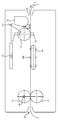
<レーザービームプリンターの概略構成>
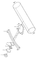
まず、このレーザービームプリンターの概略構成を、図1の側面構成図に基づいて説明する。このレーザービームプリンターは、外部のパソコン等に接続されて使用されるとともに、このパソコン等から送信されてきた印字データ(画像データを含む)を、連続紙(ファンフォールド紙)P上に印字するものである。
<Schematic configuration of laser beam printer>
First, a schematic configuration of this laser beam printer will be described based on a side configuration diagram of FIG. This laser beam printer is used while connected to an external personal computer, etc., and prints print data (including image data) transmitted from this personal computer on continuous paper (fanfold paper) P It is.
図1において、この感光ドラム12の周囲には、時計回りに、帯電部13,反射ミラー11,現像部14,及び、転写部15が順に設けられている。そして、感光ドラム12が図中時計回りに回転すると、先ず、帯電部13が感光ドラム12の表面を帯電させる。次に、反射ミラー11が、レーザースキャニングユニット(LSU)10から印字データに応じて出射された走査光(変調光)を、感光ドラム12に向けて反射し、この感光ドラム12の表面に静電潜像を形成する。次に、現像部14がこの静電潜像にトナーを付着させて、トナー像として顕像化する。次に、転写部15が、ファンフォールド紙P上にこのトナー像を転写する。
In FIG. 1, a
このファンフォールド紙Pは、レーザービームプリンターの供給口Aから排出口Bまで引き通された連続紙であり、その両側縁には、一定ピッチで送り孔(図示略)が開けられている。トラクタ16は、この送り孔に嵌合する突起16aが多数形成されたベルトコンベアであり、この突起16aによって、ファンフォールド紙Pを感光ドラム12の回転周速と同一速度で搬送する。
The fanfold paper P is a continuous paper drawn from the supply port A to the discharge port B of the laser beam printer, and feed holes (not shown) are opened at a constant pitch on both side edges. The
このトラクタ16によって搬送されるファンフォールド紙Pの下流側には、このファンフォールド紙Pを両面側から挟み込んで圧接するヒートロール17及びプレスロール18が設けられている。このヒートロール17は、その内部に発熱用のハロゲンランプ19を内蔵しており、図示せぬモータによってファンフォールド紙Pの搬送速度と同一の回転周速で回転駆動される。一方、プレスロール18は、一定圧力でヒートロール17に圧接しており、ヒートロール17の回転により回転駆動される。従って、ファンフォールド紙Pのトナー像が転写されている部分がこのヒートロール17とプレスロール18との間を通過すると、トナーが熱と圧力によって押し潰されてファンフォールド紙P上に溶着されて、トナー像が定着されるのである。
On the downstream side of the fanfold paper P conveyed by the
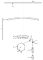
<LSUの光学構成>
次に、LSU10に内蔵されている走査光学系について、説明する。図2は、走査光学系の概略的な光学構成図である。図2に示されるように、この走査光学系は、レーザー光源1,コリメートレンズ(コリメータ)2,位相シフト素子3、開口絞り4,シリンドリカルレンズ5,ポリゴンミラー6及びfθレンズ群7を、備えている。
<Optical configuration of LSU>
Next, the scanning optical system built in the
レーザー光源1から発散光として射出されるレーザービームは、コリメートレンズ2を透過することによって断面楕円形の平行光束に変換された後、位相シフト素子3,開口絞り4及びシリンドリカルレンズ5を順に経て、等角速度で回転するポリゴンミラー6の反射面によって動的に偏向される。ポリゴンミラー6により偏向されたレーザービームは、結像光学系であるfθレンズ群7(焦点距離135.5mm)を構成する第1乃至第3レンズ7a〜7cを順に透過することにより、走査対象面S上を露光するスポット光として収束され、ポリゴンミラー6の回転に伴って感光ドラム12の表面(走査対象面)S上を主走査方向に沿って等速度に走査する。スポット光は、走査対象面S上に線状の軌跡(走査線)を描くが、走査対象面S自体が、主走査方向に直交する副走査方向へ等速度で移動されるので、走査対象面S上には、複数の走査線が等間隔に形成される。また、このように走査対象面S上で繰り返し走査されるレーザービームは、図示せぬ変調器(又はレーザー光源1そのもの)により、画像情報に従ってオンオフ変調されているので、走査対象面S上には、複数のドットからなる二次元状の画像が描画される。
The laser beam emitted as divergent light from the
なお、シリンドリカルレンズ5を透過したレーザービームは、主走査方向においては、平行光束のままポリゴンミラー6で反射され、fθレンズ群7の収束パワーによって走査対象面S上にて収束されるが、副走査方向においては、シリンドリカルレンズ5の収束パワーによってポリゴンミラー6の反射面近傍で一旦収束され、発散光としてfθレンズ群7に入射し、fθレンズ群7の収束パワーによって再び走査対象面S上に収束される。このとき、ポリゴンミラー6の反射面近傍と走査対象面Sとがfθレンズ群7によって副走査方向において光学的に共役となっているために、ポリゴンミラー6の各反射面の僅かな傾き(いわゆる「面倒れ」)による走査対象面S上の走査位置の副走査方向へのずれが、補正される。
The laser beam transmitted through the cylindrical lens 5 is reflected by the polygon mirror 6 as a parallel light beam in the main scanning direction and converged on the scanning target surface S by the convergence power of the
<位相シフト素子>
次に、位相シフト素子3について、説明する。この位相シフト素子3は、コリメートレンズ2から射出されるレーザービームの一部光束に対して位相差を付与する光学素子であり、レーザービームのビーム中心軸に対して直交するように配置される矩形の透明平板である。
<Phase shift element>
Next, the
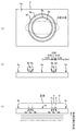
図3(a)は、位相シフト素子3の正面図である。図3(a)に示されるように、この位相シフト素子3を構成する透明平板の一側面(正面)は、その中心に位置する円形の中央領域3aと、この中央領域3aが内接する輪帯状の第1領域3bと、この第1領域3bが内接する開口円を内部中心に有する矩形の第2領域3cとに、区分されている。
FIG. 3A is a front view of the
中央領域3aは、レーザー光源1からコリメートレンズ2を介して入射するレーザービームのうちのビーム中心軸及びその近傍の光束を透過させる領域である。一方、第1及び第2領域3b,3cは、入射してくるレーザービームの一部を透過させるとともに、中央領域3aを透過する光束との間に所定の位相差をもたせるようにその光束に対して作用する領域である。
The
より具体的には、第1領域3bは、自身を透過する光束に対して所定の位相差を持たせるために、光軸方向の厚みを中央領域3aの厚みよりも僅かな量だけ増量又は減量されている。また、第2領域3cは、自身を透過する光束に対して所定の位相差を持たせるために、光軸方向の厚みを中央領域3aの厚みよりも僅かな量だけ増量又は減量され、或いは、中央領域3aの光軸方向の厚みと同じ厚みにされている。
More specifically, the
これら第1及び第2領域3b,3cにおける光軸方向の厚みの増量又は減量Δd[nm]は、その材質の屈折率をn、レーザービームの波長をλ[nm]、目的とする位相差をΔφ[rad]とすると、Δd=Δφ・λ/2π(n−1)によって決定されている。
The increase or decrease Δd [nm] of the thickness in the optical axis direction in the first and
第1の実施形態では、中央領域3aを透過した後の光束に対し、第1領域3bを透過した後の光束が持つ位相差θは、半波長(λ/2[nm])の光路長差に相当するπ[rad]に、設定されている。また、中央領域3aを透過した後の光束に対し、第2領域3cを透過した後の光束が持つ位相差θ'は、0[rad]に設定されている。なお、これらは、cosθ=-1、cosθ'=1となり、条件式(1)及び(2)を満足している。
In the first embodiment, the phase difference θ of the light beam after passing through the
従って、位相シフト素子3の側面図である図3(b)に示されるように、第1の実施形態では、第1領域3bは、光軸方向の厚みを中央領域3aの厚みよりも僅かな量だけ増されているとともに、第2領域3cは、中央領域3aの光軸方向の厚みと同じになっている。すなわち、位相シフト素子3全体は、円環体(母線が矩形である回転体)状の突出部3dが透明平板と一体に形成されたものとなっている。但し、図3(b)では、第1領域3bの光軸方向の厚みは誇張されており、実際には、位相シフト素子3の正面は殆ど平坦である。
Therefore, as shown in FIG. 3B, which is a side view of the
なお、上述した円環体状の突出部3dは、金型を用いた成型やエッチングによって透明平板とともに一体形成されても良いが、別体に形成されても良い、別体の場合には、この突出部3dは、蒸着などにより透明平板に施されたコーティング、若しくは透明平板に貼り付けられたフィルムとして、構成され得る。
In addition, although the torus-shaped
ところで、位相シフト素子3に入射してくるレーザービームの断面は、上述したように、コリメートレンズ2によって楕円形状に整形される(図3(a)の破線を参照)とともに、その長軸が主走査方向に、その短軸が副走査方向に向けられる。第1の実施形態では、位相シフト素子3に入射してくるレーザービームの断面形状における長軸の半径は、1.35mmに設定されており、その短軸の半径は、0.5mmに設定されている。また、図3(b)に示されるように、第1領域3bの径方向の幅は、0.05mmであり、その内径は、1.90mmである。このため、位相シフト素子3へ入射した光束は、中央領域3a並びに第1及び第2領域3b,3cの何れかを透過することとなる。
Incidentally, as described above, the cross section of the laser beam incident on the
図3(c)は、レーザービームが位相シフト素子3を透過する前後での波面の状態を示す概念図である。この図3(c)に示されるように、中央領域3aを透過した光束の波面を基準とすると、第1領域3bを透過した光束には、π[rad]の位相差が付与され、第2領域3cを透過した光束には、0[rad]の位相差が付与される。従って、第1の実施形態では、コリメートレンズ2からのレーザービームのうち、大部分の光束(中央領域3a及び第2領域3cに入射するの光束)は、透明平板をそのまま透過するとともに、ほんの一部の光束(第1領域3bに入射する光束)だけが、π[rad]の位相差を付与される。
FIG. 3C is a conceptual diagram showing the state of the wave front before and after the laser beam passes through the
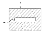
<開口絞り>
次に、開口絞り4について、説明する。この開口絞り4は、図4に示されるように、主走査方向に長手方向を向けたスリット4aが開口(アパーチャ)として穿たれている平板である。
<Aperture stop>
Next, the
<第1の実施形態の機能>
以下、以上のように構成される第1の実施形態の走査光学系によって走査対象面S上で走査されるレーザービームの強度分布を、位相シフト素子3がなかったときと、位相シフト素子3があったときと、六分の一波長(λ/6[nm])の光路差に相当するπ/3[rad]の位相差を付与するように設定された位相シフト素子が仮にあったときとで比較して説明する。
<Functions of First Embodiment>
Hereinafter, the intensity distribution of the laser beam scanned on the scanning target surface S by the scanning optical system according to the first embodiment configured as described above is obtained when there is no
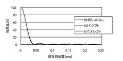
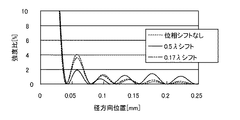
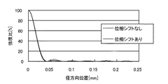
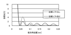
図5は、走査対象面Sに入射するレーザービームの強度分布を、そのビーム中心軸から主走査方向へ0.25mmまでの範囲において、示したグラフである。このグラフでは、各地点の強度は、ビーム中心軸上での最大強度値に対する比率によって表示されている。また、図6は、図5のグラフにおける強度比率が0%から10%までの範囲を拡大して示したグラフである。そして、これら図5及び図6では、破線によって示される曲線が、位相シフト素子3がなかったときの強度分布を示し、実線によって示される曲線が、位相シフト素子3があったときの強度分布を示し、二点鎖線によって示される曲線が、位相差をπ/ 3[rad]にするように設定された位相シフト素子が仮にあったときの強度分布を示す。
FIG. 5 is a graph showing the intensity distribution of the laser beam incident on the scanning target surface S in a range from the beam central axis to 0.25 mm in the main scanning direction. In this graph, the intensity at each point is displayed as a ratio to the maximum intensity value on the beam center axis. FIG. 6 is an enlarged graph showing the intensity ratio range from 0% to 10% in the graph of FIG. In FIGS. 5 and 6, the curve indicated by the broken line indicates the intensity distribution when the
位相シフト素子3がなかったとき(図5及び図6の破線参照)は、サイドローブの強度は、メインビームから離れるに従って徐々に弱くなっており、メインビームに隣接するサイドローブの強度は、4%強となっている。 When there is no phase shift element 3 (see the broken lines in FIGS. 5 and 6), the intensity of the side lobe gradually decreases as the distance from the main beam increases, and the intensity of the side lobe adjacent to the main beam is 4 It is slightly over%.
また、位相差をπ/ 3[rad]にするように設定された位相シフト素子が仮にあったとき(図5及び図6の二点鎖線参照)も、サイドローブの強度は、メインビームから離れるに従って徐々に弱くなっており、メインビームに隣接するサイドローブの強度は、3.5%程度となっている。 Further, when there is a phase shift element set so that the phase difference is π / 3 [rad] (see the two-dot chain line in FIGS. 5 and 6), the intensity of the side lobe is separated from the main beam. The strength of the side lobe adjacent to the main beam is about 3.5%.
これらに対し、位相シフト素子3があったとき(図5及び図6の実線参照)は、サイドローブの強度は、ほぼ平均的であり、何れも、2%弱となっている。
On the other hand, when the
従って、fθレンズ群7の各レンズ7a〜7cのレンズ面に多少の微視的なうねりがあり、サイドローブの強度が、数%程度だけ上昇したとしても、感光ドラム12に感光される強度の閾値を、超えることは少ない。
Accordingly, even if the lens surfaces of the
ところで、位相シフト素子3を正面から見たとき(図3(a))において、第1領域3bのうちのレーザービームが入射する領域の面積S'は、レーザービームの断面の面積Sに対し、適切に設定されることが望ましい。第1の実施形態では、S’は0.08であり、Sは2.12であるので、S’/Sは0.04である。従って、第1の実施形態の走査光学系は、上記条件式(3)を満足している。
By the way, when the
なお、上記の説明では、第1領域3bは、輪帯状に形成されている(図3(a)参照)が、これに限られるものではなく、例えば、矩形や多角形の環状に形成されていても良い。そのうえ、上記の説明のように、レーザービームの断面形状を円形ではなく楕円状にすることによって、第1領域3bにレーザービームが入射しない部分が存在する場合には、第1領域3bを、その部分を持たないように形成することもできる。この場合、第1領域3bは、互いに離れた幾つかの部分から構成されることとなる。
In the above description, the
また、上記の説明では、位相シフト素子3と開口絞り4とが別体であるとしたが、これらは、一体に構成されたものであっても良い。例えば、位相シフト素子3と開口絞り4とが接着されることによって一体に構成されたものであっても良いし、図7に示されるように、上記スリット4aと等価な開口が形成された透過率0%のフィルム(若しくはコーティング)を、上記位相シフト素子3における突出部3dのない側面に貼り付けたものであっても良い。
In the above description, the
さらに、上記の説明では、fθレンズ群7を結像光学系として有するいわゆる透過型の走査光学系に対して本発明を適用した例を示したが、図8に示されるようなfθミラー7’を結像光学系として有するいわゆる反射型の走査光学系に対して本発明を適用することもできる。なお、反射型の走査光学系では、透過型に比べると、結像光学系の光学面の微視的なうねりに因るサイドローブ強度の増加量が大きい。そのため、反射型の走査光学系では、ハーフトーン印字時の黒スジがより発生し易くなる。そこで、反射型の走査光学系に本発明を適用することによる、サイドローブを低減し、黒スジの発生をより少なくすることができる。
Furthermore, in the above description, an example in which the present invention is applied to a so-called transmission type scanning optical system having the
第2の実施形態は、位相シフト素子の第2領域が光束に付与する位相差が第1の実施形態のものと異なる他は、第1の実施形態と同じ構成を有する。従って、以下では、第1の実施形態との相違点のみについて、説明する。 The second embodiment has the same configuration as the first embodiment except that the phase difference imparted to the light flux by the second region of the phase shift element is different from that of the first embodiment. Therefore, only the differences from the first embodiment will be described below.
図9(a)は、第2の実施形態の位相シフト素子8の正面図であり、図9(b)は、この位相シフト素子8の側面図であり、図9(c)は、この位相シフト素子8をレーザービームが透過する前後での波面の状態を示す概念図である。
FIG. 9A is a front view of the
図9(a)に示されるように、第2の実施形態の位相シフト素子8も、第1の実施形態の位相シフト素子3と同様に、中央領域8aと、この中央領域8aが内接する輪帯状の第1領域8bと、この第1領域8bが内接する開口円を内部中心に有する矩形の第2領域8cとを、有する。
As shown in FIG. 9 (a), the
但し、第1の実施形態とは異なり、中央領域8aを透過した後の光束に対し、第2領域8cを透過した後の光束が持つ位相差θ'は、一波長(λ[nm])の光路長差に相当する−2π[rad]に設定されている。これは、cosθ'=1となり、条件式(2)を満足している。なお、中央領域8aを透過した後の光束に対し、第1領域8bを透過した後の光束が持つ位相差θは、第1の実施形態と同様に、半波長(λ/2[nm])の光路長差に相当する−π[rad]に、設定されている。よって、これは、cosθ=-1となり、条件式(1)を満足している。
However, unlike the first embodiment, the phase difference θ ′ of the light beam after passing through the
従って、図9(b)に示されるように、第2の実施形態では、第1領域8bの光軸方向の厚みは、中央領域8aの厚みよりも僅かな量Δd[nm]だけ薄くなっているとともに、第2領域8cの光軸方向の厚みは、第1領域8bの厚みが減らされている分の2倍の量2Δd[nm]だけ、中央領域8aの厚みよりも薄くなっている。つまり、位相シフト素子8全体は、段状の突出部8dが透明平板と一体に形成されたものとなっている。但し、図9(b)では、第1及び第2領域8b,8cの光軸方向の厚みは誇張されており、実際には、位相シフト素子8の正面は殆ど平坦である。
Therefore, as shown in FIG. 9B, in the second embodiment, the thickness of the
そして、図9(c)の概念図に示されるように、中央領域8aを透過した光束を基準とすると、第1領域8bを透過した光束には、半波長(λ/2[nm])の光路長差に相当する−π[rad]だけ、位相差が付与され、第2領域8cを透過した光束には、一波長(λ)の光路長差に相当する−2π[rad]だけ、位相差が付与される。従って、中央領域8aと第2領域8cを透過した光束は同位相となり、第1領域8bに入射した光束のみに、−π[rad]の位相差が付与されることになる。このため、図9の位相シフト素子8は、図3の位相シフト素子3と同等に機能することになる。すなわち、第2の実施形態の位相シフト素子8を走査光学系に用いても、図5及び図6と同じ結果が得られる。
Then, as shown in the conceptual diagram of FIG. 9C, when the light beam transmitted through the
なお、図9の位相シフト素子8も、図3の位相シフト素子3と同様に、開口絞り4と一体に構成されていても良い。また、図9の位相シフト素子8は、図8のような反射型の走査光学系に用いられても良い。さらに、位相差をつける方向が逆向きでも良い。
Note that the
第3の実施形態は、光束に位相差を付与する領域を4つ備えた位相シフト素子を用いている他は、第1の実施形態と同じ構成を有する。従って、以下では、第1の実施形態との相違点のみについて、説明する。 The third embodiment has the same configuration as that of the first embodiment, except that a phase shift element including four regions for imparting a phase difference to a light beam is used. Therefore, only the differences from the first embodiment will be described below.
図10(a)は、第3の実施形態の位相シフト素子9の正面図であり、図10(b)は、この位相シフト素子9の側面図であり、図10(c)は、この位相シフト素子9をレーザービームが透過する前後での波面の状態を示す概念図である。
FIG. 10A is a front view of the
第3の実施形態の位相シフト素子9も、光軸に対して直交するように配置される矩形の透明平板である。この位相シフト素子9を構成する透明平板の一側面(正面)は、図10(a)に示されるように、その中心に位置する円形の中央領域9aと、この中央領域9aが内接する輪帯状の第1領域9bと、この第1領域9bが内接する輪帯状の第2領域9cと、この第2領域9cが内接する輪帯状の第3領域9dと、この第3領域9dが内接する開口円を内部中心に有する矩形の第4領域9eとに、区分されている。
The
中央領域9aは、レーザー光源1からコリメートレンズ2を介して入射するレーザービームのうちのビーム中心軸及びその近傍の光束を透過させる領域である。一方、第1乃至第4領域9b〜9eは、入射してくるレーザービームの一部を透過させるとともに、中央領域9aを透過する光束との間に所定の位相差をもたせるようにその光束に対して作用する領域である。
The
第3の実施形態では、中央領域9aを透過した後の光束に対し、第1領域9b及び第3領域9dを透過した後の光束が持つ位相差θは、半波長(λ/2[nm])の光路長差に相当するπ[rad]に、設定されている。また、中央領域9aを透過した後の光束に対し、第2領域9c及び第4領域9eを透過した後の光束が持つ位相差θ'は、0[rad]に設定されている。なお、これらは、cosθ=-1、cosθ'=1となり、条件式(1)及び(2)を満足している。
In the third embodiment, the phase difference θ of the light beam after passing through the
従って、図10(b)に示されるように、第3の実施形態では、第1領域9b及び第3領域9dは、光軸方向の厚みを中央領域8aの厚みよりも僅かな量だけ増されているとともに、第2領域9c及び第4領域9eは、中央領域9aの光軸方向の厚みと同じ厚みになっている。すなわち、位相シフト素子9全体は、一方の外径が他方の内径よりも小さい2つの円環体状の突出部が透明平板と一体に形成されたものとなっている。但し、図10(b)では、第1及び第3領域9b,9dの光軸方向の厚みは誇張されており、実際には、位相シフト素子9の正面は殆ど平坦である。
Therefore, as shown in FIG. 10B, in the third embodiment, the thickness of the
ところで、位相シフト素子9に入射してくるレーザービームの断面は、コリメートレンズ2によって楕円形状に整形される(図10(a)の破線を参照)とともに、その長軸が主走査方向に、その短軸が副走査方向に向けられる。第3の実施形態では、位相シフト素子9に入射してくるレーザービームの断面形状における長軸の半径は、1.35mmに設定されており、その短軸の半径は、0.5mmに設定されている。また、図10(b)に示されるように、第1領域9bの径方向の幅は、0.02mmであり、その内径は、1.80mmである。また、第2領域9cの径方向の幅は、0.08mmであり、第3領域9dの径方向の幅は、0.03mmである。このため、位相シフト素子9へ入射した光束は、中央領域9a及び第1乃至第4領域9b〜9eの何れかを透過することとなる。
By the way, the cross section of the laser beam incident on the
そして、図10(c)に示されるように、中央領域9aを透過した光束の波面を基準とすると、第1領域9b及び第3領域9dを透過した光束には、π[rad]の位相差が付与され、第2領域9c及び第4領域9eを透過した光束には、0[rad]の位相差が付与される。従って、第3の実施形態では、コリメートレンズ2からのレーザービームのうち、大部分の光束(中央領域9a,第2領域9c及び第4領域9eに入射するの光束)は、透明平板をそのまま透過するとともに、ほんの一部の光束(第1領域9b及び第3領域9dに入射する光束)だけが、π[rad]の位相差を付与される。
As shown in FIG. 10C, when the wavefront of the light beam transmitted through the
<第3の実施形態の機能>
以下、以上のように構成される第3の実施形態の走査光学系によって走査対象面S上で走査されるレーザービームの強度分布を、位相シフト素子9がなかったときと、位相シフト素子9があったときとで比較して説明する。
<Function of Third Embodiment>
Hereinafter, the intensity distribution of the laser beam scanned on the scanning target surface S by the scanning optical system according to the third embodiment configured as described above is obtained when there is no
図11は、走査対象面Sに入射するレーザービームの強度分布を、そのビーム中心軸から主走査方向へ0.25mmまでの範囲において、示したグラフである。このグラフでは、各地点の強度は、ビーム中心軸上での最大強度値に対する比率によって表示されている。また、図12は、図11のグラフにおける強度比率が0%から10%までの範囲を拡大して示したグラフである。そして、これら図11及び図12では、破線によって示される曲線が、位相シフト素子9がなかったときの強度分布を示し、実線によって示される曲線が、位相シフト素子9があったときの強度分布を示す。
FIG. 11 is a graph showing the intensity distribution of the laser beam incident on the scanning target surface S in a range from the beam central axis to 0.25 mm in the main scanning direction. In this graph, the intensity at each point is displayed as a ratio to the maximum intensity value on the beam center axis. FIG. 12 is a graph showing the intensity ratio in the graph of FIG. 11 in an enlarged manner from 0% to 10%. 11 and 12, the curve indicated by the broken line shows the intensity distribution when the
位相シフト素子9がなかったとき(図11及び図12の破線参照)は、サイドローブの強度は、メインビームから離れるに従って徐々に弱くなっており、メインビームに隣接するサイドローブの強度は、4%強となっている。 When there is no phase shift element 9 (see the broken lines in FIGS. 11 and 12), the intensity of the side lobe gradually decreases as the distance from the main beam increases, and the intensity of the side lobe adjacent to the main beam is 4 It is slightly over%.
これに対し、位相シフト素子9があったとき(図11及び図12の実線参照)は、サイドローブの強度は、ほぼ平均的であり、何れも、2%弱となっている。
On the other hand, when the
従って、fθレンズ群7の各レンズ7a〜7cのレンズ面に多少の微視的なうねりがあり、サイドローブの強度が、数%程度だけ上昇したとしても、感光ドラム12に感光される強度の閾値を、超えることは少ない。
Accordingly, even if the lens surfaces of the
ところで、位相シフト素子3を正面から見たとき(図10(a))において、第1領域9bのうちのレーザービームが入射する領域の面積と第3領域9dのうちのレーザービームが入射する領域の面積との総和S’は、レーザービームの断面の面積Sに対し、適切に設定されることが望ましい。第3の実施形態では、S’は0.08であり、Sは2.12であるので、S’/Sは0.04である。従って、第3の実施形態の走査光学系は、上記条件式(3)を満足している。
By the way, when the
なお、図10の位相シフト素子9も、図3の位相シフト素子3と同様に、開口絞り4と一体に構成されていても良い。また、図10の位相シフト素子9は、図8のような反射型の走査光学系に用いられても良い。
Note that the
1 レーザー光源
2 コリメートレンズ
3 位相シフト素子
3a 中央領域
3b 第1領域
3c 第2領域
4 開口絞り
4a スリット(アパーチャー)
5 シリンドリカルレンズ
6 ポリゴンミラー
7 fθレンズ群
8 位相シフト素子
8a 中央領域
8b 第1領域
8c 第2領域
9 位相シフト素子
9a 中央領域
9b 第1領域
9c 第2領域
9d 第3領域
9e 第4領域
DESCRIPTION OF
DESCRIPTION OF SYMBOLS 5 Cylindrical lens 6 Polygon mirror 7 f (theta)
Claims (10)
前記光源と前記偏向器との間の光路上に、光学素子を備え、
前記光学素子は、
前記光源から発せられる平行なレーザービームのうちのビーム中心軸及びその近傍の光束を透過させる中央領域と、
前記中央領域の外側に入射する光束の一部を透過させるとともに透過後の光束が前記中央領域を透過した光束に対して所定の第1の位相差を付与するように作用する第1外側領域と、
前記中央領域及び前記第1外側領域に入射する光束を除く光束の一部を透過させるとともに透過後の光束が前記中央領域を透過した光束に対して所定の第2の位相差を付与するように作用する第2外側領域と
を有し、
前記各外側領域は、前記中央領域から前記主走査方向における両側に向かって順に、配置されており、
前記第1の位相差は、整数をNとしたとき、(2N−1)π[rad]であるとともに、
前記第2の位相差は、整数をMとしたとき、2Mπ[rad]である
ことを特徴とする走査光学系。 A parallel laser beam emitted from a light source is dynamically deflected by a deflector, and the dynamically deflected laser beam is converged as a spot light on a scanning target surface by an imaging optical system. Scanning optical system that scans along the main scanning direction on the surface to be scanned,
An optical element is provided on the optical path between the light source and the deflector,
The optical element is
A central region for transmitting a beam central axis of the parallel laser beams emitted from the light source and a light beam in the vicinity thereof; and
A first outer region that transmits a part of the light beam incident on the outside of the central region and acts so that the transmitted light beam gives a predetermined first phase difference to the light beam transmitted through the central region; ,
A part of the light beam excluding the light beam incident on the central region and the first outer region is transmitted, and the transmitted light beam gives a predetermined second phase difference to the light beam transmitted through the central region. A second outer region acting;
Each outer region is arranged in order from the central region toward both sides in the main scanning direction,
The first phase difference is (2N−1) π [rad], where N is an integer,
The scanning optical system according to claim 2, wherein the second phase difference is 2M [pi] [rad] where M is an integer .
ことを特徴とする請求項1記載の走査光学系。 The first outer area includes a scanning optical system according to claim 1, characterized in that adjacent thereto on the outside of the central region.
ことを特徴とする請求項1又は2記載の走査光学系。 The second outer region, according to claim 1 or 2 scanning optical system according to, characterized in that adjacent to this on the outside of the first outer region.
ことを特徴とする請求項1、2又は3記載の走査光学系。 The optical element, according to claim 1, 2 or 3 scanning optical system according to characterized in that it comprises a plurality of sets of said first and second outer region.
ことを特徴とする請求項4記載の走査光学系。 5. The scanning optical system according to claim 4 , wherein the first and second outer regions are alternately arranged in a direction away from the central region.
ことを特徴とする請求項1乃至5の何れかに記載の走査光学系。 Between regions to be imparted to the light beam the same as each other phase difference among the respective outer area, at symmetrical positions on both sides sandwiching the central region, according to any one of claims 1 to 5, characterized in that it is arranged Scanning optical system.
0.03<(S’/S)<0.3 ---(3)
を満足する
ことを特徴とする請求項1乃至6の何れかに記載の走査光学系。 When the total area of the regions where the laser beam is incident in the first outer region is S ′ and the area of the cross section perpendicular to the beam central axis in the laser beam is S, the following conditional expression (3) ,
0.03 <(S '/ S) <0.3 --- (3)
The scanning optical system according to claim 1, wherein:
ことを特徴とする請求項1乃至7の何れかに記載の走査光学系。 The imaging optical system, the scanning optical system according to any one of claims 1 to 7, characterized in that an optical system comprising a reflecting surface.
ことを特徴とする請求項1乃至8の何れかに記載の走査光学系。 Said optical element has a shielding portion as an aperture stop, in the opening portion, the scanning optical system according to any one of claims 1 to 8, characterized in that the central region and the respective outer regions, with .
前記光源と前記偏向器との間の光路上に、光学素子を備え、
前記光学素子は、
前記光源から発せられる平行なレーザービームのうちのビーム中心軸及びその近傍の光束を透過させる中央領域と、
前記中央領域の外側に入射する光束の一部を透過させるとともに透過後の光束が前記中央領域を透過した光束に対して所定の第1の位相差を付与するように作用する第1外側領域と、
前記中央領域及び前記第1外側領域に入射する光束を除く光束の一部を透過させるとともに透過後の光束が前記中央領域を透過した光束に対して所定の第2の位相差を付与するように作用する第2外側領域と
を有し、
前記各外側領域は、前記中央領域から前記主走査方向における両側に向かって順に、配置されており、
前記第1の位相差は、整数をNとしたとき、(2N−1)π[rad]であるとともに、
前記第2の位相差は、整数をMとしたとき、2Mπ[rad]である
ことを特徴とするプリンター。 A parallel laser beam emitted from a light source is dynamically deflected by a deflector, and the dynamically deflected laser beam is converged as a spot light on a scanning target surface by an imaging optical system. A printer comprising a scanning optical system that scans along the main scanning direction on the surface to be scanned,
An optical element is provided on the optical path between the light source and the deflector,
The optical element is
A central region for transmitting a beam central axis of the parallel laser beams emitted from the light source and a light beam in the vicinity thereof; and
A first outer region that transmits a part of the light beam incident on the outside of the central region and acts so that the transmitted light beam gives a predetermined first phase difference to the light beam transmitted through the central region; ,
A part of the light beam excluding the light beam incident on the central region and the first outer region is transmitted, and the transmitted light beam gives a predetermined second phase difference to the light beam transmitted through the central region. A second outer region acting;
Each outer region is arranged in order from the central region toward both sides in the main scanning direction,
The first phase difference is (2N−1) π [rad], where N is an integer,
The printer, wherein the second phase difference is 2M [pi] [rad] where M is an integer .
Priority Applications (1)
| Application Number | Priority Date | Filing Date | Title |
|---|---|---|---|
| JP2003308329A JP4366147B2 (en) | 2002-09-03 | 2003-09-01 | Scanning optical system and printer |
Applications Claiming Priority (2)
| Application Number | Priority Date | Filing Date | Title |
|---|---|---|---|
| JP2002258085 | 2002-09-03 | ||
| JP2003308329A JP4366147B2 (en) | 2002-09-03 | 2003-09-01 | Scanning optical system and printer |
Publications (2)
| Publication Number | Publication Date |
|---|---|
| JP2004118182A JP2004118182A (en) | 2004-04-15 |
| JP4366147B2 true JP4366147B2 (en) | 2009-11-18 |
Family
ID=32301432
Family Applications (1)
| Application Number | Title | Priority Date | Filing Date |
|---|---|---|---|
| JP2003308329A Expired - Fee Related JP4366147B2 (en) | 2002-09-03 | 2003-09-01 | Scanning optical system and printer |
Country Status (1)
| Country | Link |
|---|---|
| JP (1) | JP4366147B2 (en) |
Families Citing this family (3)
| Publication number | Priority date | Publication date | Assignee | Title |
|---|---|---|---|---|
| JP2005296412A (en) | 2004-04-13 | 2005-10-27 | Olympus Corp | Endoscopic treatment apparatus |
| WO2010016142A1 (en) * | 2008-08-08 | 2010-02-11 | ナルックス株式会社 | Phase shifting plate and optical system provided with phase shifting plate |
| JP5105253B2 (en) * | 2008-11-25 | 2012-12-26 | 株式会社リコー | Optical scanning apparatus, image forming apparatus, and multicolor image forming apparatus |
-
2003
- 2003-09-01 JP JP2003308329A patent/JP4366147B2/en not_active Expired - Fee Related
Also Published As
| Publication number | Publication date |
|---|---|
| JP2004118182A (en) | 2004-04-15 |
Similar Documents
| Publication | Publication Date | Title |
|---|---|---|
| JP4842747B2 (en) | Optical scanning apparatus, image forming apparatus, and color image forming apparatus | |
| JP4612842B2 (en) | Optical scanning device | |
| JP4850358B2 (en) | Scanning optical device and image forming apparatus using the same | |
| JP4650526B2 (en) | Optical scanning device | |
| JP2025015560A (en) | Optical scanner | |
| US7791632B2 (en) | Optical scanning device and image forming apparatus using the same | |
| US8310517B2 (en) | Optical scanning device and image forming apparatus | |
| US20090046343A1 (en) | Optical scanner configured so a principal ray of an incident beam from a light source to a deflector and a principal ray of a scanning beam from the deflector to a scanned surface travel on opposite sides of an optical axis of optical element(s) having transmissive surfaces both concave toward the deflector in sub-scanning section, and image forming apparatus using the same | |
| US6496293B2 (en) | Optical scanning device, scanning optical system, optical scanning method and image forming apparatus | |
| JP4566398B2 (en) | Optical scanning device, multi-beam scanning device, and image forming apparatus | |
| US7042608B2 (en) | Scanning optical system | |
| US7550712B2 (en) | Optical scanning system with reduced spherical aberration and image forming apparatus using the same | |
| JP4366147B2 (en) | Scanning optical system and printer | |
| US6977781B2 (en) | Scanning optical system | |
| JP4381116B2 (en) | Scanning optical system and printer | |
| US7019768B2 (en) | Scanning optical system | |
| JP4412948B2 (en) | Scanning optical system and printer | |
| US7355773B2 (en) | Optical scanning apparatus and image forming apparatus using same | |
| JP4612767B2 (en) | Scanning optical system and image forming apparatus using the scanning optical system | |
| JP2005017896A (en) | Optical scanning device and image forming apparatus using the same | |
| JP4489852B2 (en) | Exposure apparatus and image forming apparatus | |
| JP4323652B2 (en) | Optical scanning device and image forming apparatus using the same | |
| JP4551569B2 (en) | Optical scanning device and image forming apparatus using the same | |
| JP4378416B2 (en) | Scanning optical device and image forming apparatus using the same | |
| JP2004109588A (en) | Multibeam laser emission unit and image forming device |
Legal Events
| Date | Code | Title | Description |
|---|---|---|---|
| A521 | Written amendment |
Free format text: JAPANESE INTERMEDIATE CODE: A523 Effective date: 20030905 |
|
| A621 | Written request for application examination |
Free format text: JAPANESE INTERMEDIATE CODE: A621 Effective date: 20050915 |
|
| A711 | Notification of change in applicant |
Free format text: JAPANESE INTERMEDIATE CODE: A712 Effective date: 20080425 |
|
| A977 | Report on retrieval |
Free format text: JAPANESE INTERMEDIATE CODE: A971007 Effective date: 20081104 |
|
| A131 | Notification of reasons for refusal |
Free format text: JAPANESE INTERMEDIATE CODE: A131 Effective date: 20081111 |
|
| A521 | Written amendment |
Free format text: JAPANESE INTERMEDIATE CODE: A523 Effective date: 20090107 |
|
| TRDD | Decision of grant or rejection written | ||
| A01 | Written decision to grant a patent or to grant a registration (utility model) |
Free format text: JAPANESE INTERMEDIATE CODE: A01 Effective date: 20090811 |
|
| A01 | Written decision to grant a patent or to grant a registration (utility model) |
Free format text: JAPANESE INTERMEDIATE CODE: A01 |
|
| A61 | First payment of annual fees (during grant procedure) |
Free format text: JAPANESE INTERMEDIATE CODE: A61 Effective date: 20090824 |
|
| FPAY | Renewal fee payment (event date is renewal date of database) |
Free format text: PAYMENT UNTIL: 20120828 Year of fee payment: 3 |
|
| R150 | Certificate of patent or registration of utility model |
Free format text: JAPANESE INTERMEDIATE CODE: R150 |
|
| FPAY | Renewal fee payment (event date is renewal date of database) |
Free format text: PAYMENT UNTIL: 20130828 Year of fee payment: 4 |
|
| LAPS | Cancellation because of no payment of annual fees |