JP4365978B2 - Packet communication system and base station in packet communication system - Google Patents
Packet communication system and base station in packet communication system Download PDFInfo
- Publication number
- JP4365978B2 JP4365978B2 JP2000073334A JP2000073334A JP4365978B2 JP 4365978 B2 JP4365978 B2 JP 4365978B2 JP 2000073334 A JP2000073334 A JP 2000073334A JP 2000073334 A JP2000073334 A JP 2000073334A JP 4365978 B2 JP4365978 B2 JP 4365978B2
- Authority
- JP
- Japan
- Prior art keywords
- base station
- mobile station
- packet data
- station
- soft handoff
- Prior art date
- Legal status (The legal status is an assumption and is not a legal conclusion. Google has not performed a legal analysis and makes no representation as to the accuracy of the status listed.)
- Expired - Fee Related
Links
Images


Description
【0001】
【発明の属する技術分野】
本発明は、パケット通信システム及びパケット通信システムにおける基地局に関する。
【0002】
【従来の技術】
移動体通信システムにおいて、ある基地局が統括するエリア内を移動中の移動局が、隣接する他の基地局が統括するエリアへ移動する際、通信障害の発生なしに2つのエリアの境界を越えるためのソフトハンドオフ技術は極めて重要な技術であり、注力されている。
特に、CDMA方式を用いた移動体通信システムにおいて、送信電力制御やRAKE受信等、種々の技術が開示されている。
これに反して、パケット通信方式でのソフトハンドオフ技術の技術開発は、あまり進んでいない。
【0003】
【発明が解決しようとする課題】
パケット通信方式では、以下に記す解決すべき大きな課題が残されているため、上記の通りソフトハンドオフ技術の技術開発があまり進んでいない。
即ち、ある基地局の統括するエリア内を移動中の移動局が隣接する他の基地局の統括するエリアへ移動する際、ある基地局で交信中の移動局の数量と、隣接する他の基地局で交信中の移動局の数量とは、異なる場合が多い。この場合に、移動中の移動局は、それぞれの基地局から受けとる有効なパケットデータを異なったタイミングで受信してしまう。従って、移動局は、受け取った有効なパケットデータを選択合成できなくなる、という解決すべき大きな課題が残されていた。
【0004】
【課題を解決するための手段】
本発明は以下の構成を採用する。
〈構成1〉 複数個の基地局と前記基地局を制御してソフトハンドオフを実行する基地局制御装置とを有するパケット通信システムであって、前記基地局制御装置は、移動局が第一の基地局が統括するエリアから該第一の基地局が統括するエリアと第二の基地局が統括するエリアとの重複部分に移動し該移動局がソフトハンドオフへ移行したことを検知すると、前記移動局宛てのパケットデータを前記第一の基地局と前記第二の基地局の双方へ重複して送出し、前記第一の基地局は、前記ソフトハンドオフ移行前に前記基地局制御装置から送られてきた前記移動局宛てのパケットデータについては前記ソフトハンドオフ移行後であっても前記移動局に無線送信し、前記ソフトハンドオフ移行後に前記基地局制御装置から送られてきた前記移動局宛てのパケットデータについては第1記憶部に格納し前記移動局への無線送信は行わず、前記ソフトハンドオフの完了後に前記第1記憶部に記憶した前記移動局宛てのパケットデータを破棄し、前記第二の基地局は、前記ソフトハンドオフ移行後に前記基地局制御装置から送られてきた前記移動局宛てのパケットデータについては第2記憶部に格納し該パケットの前記移動局への無線送信は行わず、前記ソフトハンドオフの完了後に前記第2記憶部に記憶した前記移動局宛てのパケットデータを前記移動局に無線送信することを特徴とするパケット通信システム。
〈構成2〉 複数の基地局を制御してソフトハンドオフを実行する基地局制御装置に接続する第一の基地局であって、移動局が第一の基地局が統括するエリアから該第一の基地局が統括するエリアと第二の基地局が統括するエリアとの重複部分に移動し該移動局がソフトハンドオフへ移行したことを検知した前記基地局制御装置が前記第一の基地局と前記第二の基地局との双方に送信した前記移動局宛てのパケットデータを記憶する記憶手段と、前記ソフトハンドオフ移行前に前記基地局制御装置から送られてきた前記移動局宛てのパケットデータについては前記ソフトハンドオフ移行後であっても前記移動局に無線送信し、前記ソフトハンドオフ移行後に前記基地局制御装置から送られてきた前記移動局宛てのパケットデータについては前記記憶手段に格納し前記移動局への無線送信しない、送信手段と、前記ソフトハンドオフの完了後に前記記憶手段に記憶した前記移動局宛てのパケットデータを破棄する破棄手段と、を有することを特徴とする第一の基地局。
【0005】
【発明の実施の形態】
以下、本発明の実施の形態を具体例を用いて説明する。
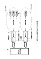
図1は、本発明による通信方式のシステム構成図である。
図1より、本発明による通信方式のシステムは、基地局1と、基地局2と、エリア7と、エリア8と、基地局制御装置9と、移動局A、移動局B、移動局C、移動局Dとを備える。
更に、基地局1には記憶部3と移動局管理テーブル5が配置され、基地局2には記憶部4と移動局管理テーブル6が配置されている。
【0006】
基地局1と、基地局2とは、ATM回線(通常有線回線)を介してパケットデータを受け入れて宛先移動局毎に所定のフレームを構成する。この所定のフレームを予め定められている所定の順番に従って電磁波に変換して自己が統括する無線エリアに放射する部分である。ここでは説明の都合上2個のみ記載してあるが、その個数はシステムによって大きく異なる。
又、自己が統括する無線エリア内に位置する移動局から電磁波に変換された所定のフレームを受け入れて電気信号に変換したあとパケットデータに分解して所定の順番に従ってATM回線へ送出する部分でもある。
【0007】
記憶部3と、記憶部4とは、基地局1と、基地局2との内部にそれぞれ配置されるメモリ部分である。ソフトハンドオフ中に当該移動局に送出すべき所定のフレームを一時格納しておく部分である。
移動局管理テーブル5と、移動局管理テーブル6とは、基地局1と、基地局2との内部にそれぞれ配置される管理テーブルである。基地局1と基地局2が、それぞれ統括する後に説明するエリア7とエリア8内に位置する移動局を管理するテーブルである。又、複数の移動局へ送出する所定のフレームの送出順番を管理する部分でもある。
【0008】
エリア7とエリア8は、上記基地局1と、基地局2とのそれぞれが、統括する無線エリアである。
移動局Aと、移動局Bと、移動局Cと、移動局Dとは、基地局1、基地局2が統括するエリア7、エリア8との内部に位置して上記基地局1、基地局2と交信して上記所定のフレームを受信する部分である。図1上では、移動局Aと、移動局Bと、移動局Cとが基地局2と交信中であり、移動局Dと基地局1とが交信中である。
【0009】
基地局制御装置9は、上記基地局1と、基地局2とを制御してソフトハンドオフを実行する部分である。
即ち、基地局制御装置9は、一例として図1における移動局Dが基地局1のエリア7と基地局2のエリア8との境界(重複部分)に移動して来たことを検知した時移動局D宛てのパケットデータをATM回線を介して基地局1と基地局2の双方へ重複して送出する部分である。又、移動局Dがエリア7又はエリア8の何れか一方のエリアへの移動を完了したことを検知したとき、上記移動局D宛てのパケットデータを、移動局Dが移動完了したエリアを統括する基地局のみに送出させる部分でもある。
【0010】
次に本発明による通信方式の動作について説明する。
本発明による通信方式の全体について説明する前に、最初に、この通信方式の基本になる単一の基地局と複数の移動局間の通信方式について説明する。
図2は、基本システム説明図である。
図2は、基地局2の統括するエリア8内に位置する移動局A、移動局B、移動局C、移動局Dが、基地局2と交信している状態を表している。
【0011】
図3は、基本動作説明図である。
(a)は、ATM回線を介して基地局2(図2)が受信するパケットデータを表している。
(b)は、基地局2(図2)が、受信したパケットデータから宛先移動局向けのフレームを構成して無線回線に送出した状態を表している。
(c)は、エリア8(図2)内に位置する移動局の局名と各移動局へ所定のフレームを送出するための所定の順番を定める移動局管理テーブルを表している。
(d)は、上記(a)、(b)、(c)共通の時間軸(横軸)上での時刻を表している。
以下に、時刻T0〜T10まで時系列的に本発明の基本動作について説明する。
【0012】
動作説明の前提条件を以下の如く定める。
前提条件1
(a)におけるA1(1)〜D1(3)の、それぞれをATM回線から送られてくるATMセル(パケットデータ)とする。ここでA1(1)とは、移動局A宛ての第1フレームの一番目のパケットデータを意味する。同様にD1(3)とは、移動局D宛ての第1フレームの三番目のパケットデータを意味する。即ち、最初の記号A、B、C、D、は、宛先移動局名であり、1、2、3、4、…はフレームの順番であり、(1)、(2)、(3)はフレーム内でのパケットデータの順番である。所定のフレームはATMセル(パケットデータ)3個によって構成されるものとする。
前提条件2
最初にエリア8(図2)内で、移動局A、移動局B、移動局Cが交信していたが、途中時刻T5で移動局Dが交信を開始し、次に時刻T7で移動局B交信を停止するものとする。
【0013】
時刻T0
基地局2(図2)は、エリア8(図2)内に位置する移動局A(図2)、移動局B(図2)、移動局C(図2)を移動局管理テーブル6(図2)に登録する。同様にフレーム送出順番をA→B→Cの順番に設定する(c)。
【0014】
時刻T1
基地局2(図2)は、移動局管理テーブル6(図2)に登録されているフレーム送出順番A→B→Cに従って、最初に移動局A宛てのパケットデータをスキャンする。しかしこの時点で基地局2(図2)は、A1(1)、A1(2)、C1(1)の3個のパケットデータを受け入れているが(a)、A1(3)を受け入れていないのでフレームPKTA1を構成できない。従って移動局A宛てのフレームを送出できない。次に移動局B宛てのパケットデータをスキャンするが、同様にフレーム構成できないので移動局B宛てのフレームを送出できない。全く同様に移動局C宛てのパケットデータをスキャンするが、同様にフレーム構成できないので移動局C宛てのフレームも送出できない(b)。
【0015】
時刻T2
基地局2(図2)は、移動局A宛てのパケットデータをスキャンする。この時点で基地局2(図2)は、A1(1)、A1(2)、C1(1)、A1(3)、C1(2)、A2(1)の6個のパケットデータを受け入れており、フレームPKTA1を構成するA1(1)、A1(2)、A1(3)の有効データを所持している。そこで、基地局2(図2)はフレームPKTA1を構成して電磁波に変換して移動局A宛てに送出する(b)。同時に後に続くフレームで移動局B宛てのパケットデータをスキャンする設定にする。
【0016】
時刻T3
基地局2(図2)は、移動局B宛てのパケットデータをスキャンする。しかしこの時点で基地局2(図2)は、フレームPKTB1を構成するB1(2)、B1(3)の有効データを所持していない。従って移動局B宛てのフレームを送出できない。次に所定の順番に従って移動局C宛てのパケットデータをスキャンする。この時点で基地局2(図2)はフレームPKTC1を構成するC1(1)、C1(2)、C1(3)の有効データを所持している。そこで基地局2(図2)はフレームPKTC1を構成して電磁波に変換して移動局C宛てに送出する(b)。同時に後に続くフレームで移動局A宛てのパケットデータをスキャンする設定にする。
【0017】
時刻T4
基地局2(図2)は、移動局A宛てのパケットデータをスキャンする。この時点で基地局2(図2)はフレームPKTA2を構成するA2(1)、A2(2)、A2(3)の有効データを所持している。そこで基地局2(図2)はフレームPKTA2を構成して電磁波に変換して移動局A宛てに送出する(b)。同時に後に続くフレームで移動局B宛てのパケットデータをスキャンする設定にする。
【0018】
時刻T5
基地局2(図2)は、移動局B宛てのパケットデータをスキャンする。この時点で基地局2(図2)はフレームPKTB1を構成するB1(1)、B1(2)、B1(3)の有効データを所持している。そこで基地局2(図2)はフレームPKTB1を構成して電磁波に変換して移動局B宛てに送出する(b)。同時に後に続くフレームで移動局C宛てのパケットデータをスキャンする設定にする。この時上記前提条件2より移動局Dが交信を開始する。基地局2(図2)は、移動局管理テーブル6(図2)の最後に移動局Dを追加する(c)。
【0019】
時刻T6
基地局2(図2)は、移動局C宛てのパケットデータをスキャンする。この時点で基地局2(図2)はフレームPKTC2を構成するC2(1)、C2(2)、C2(3)の有効データを所持している。そこで基地局2(図2)はフレームPKTC2を構成して電磁波に変換して移動局C宛てに送出する(b)。同時に後に続くフレームで移動局D宛てのパケットデータをスキャンする設定にする。
【0020】
時刻T7
基地局2(図2)は、移動局D宛てのパケットデータをスキャンする。この時点で基地局2(図2)はフレームPKTD2を構成するD1(1)、D1(2)、D1(3)の有効データを所持していない。従って移動局D宛てのフレームを送出できない。次に所定の順番に従って移動局A宛てのパケットデータをスキャンする。この時点で基地局2(図2)はフレームPKTA3を構成するA3(1)、A3(2)、A3(3)の有効データを所持している。そこで基地局2(図2)はフレームPKTA3を構成して電磁波に変換して移動局A宛てに送出する(b)。同時に後に続くフレームで移動局B宛てのパケットデータをスキャンする設定にする。
この時上記前提条件2より移動局Bが交信を停止する。基地局2(図2)は、移動局管理テーブル6(図2)から移動局Bを削除する(c)。
【0021】
時刻T8
基地局2(図2)は、本来移動局B宛てのパケットデータをスキャンする筈である。ところが移動局管理テーブル6(図2)から移動局Bは削除されているので(c)次の順番である移動局C宛てのパケットデータをスキャンする。この時点で基地局2(図2)はフレームPKTC3を構成するC3(1)、C3(2)、C(3)の有効データを所持していない。従って移動局C宛てのフレームを送出できない。次に所定の順番に従って移動局D宛てのパケットデータをスキャンする。この時点で基地局2(図2)はフレームPKTD1を構成するD1(1)、D1(2)、D1(3)の有効データを所持している。そこで基地局2(図2)はフレームPKTD1を構成して電磁波に変換して移動局D宛てに送出する(b)。同時に後に続くフレームで移動局A宛てのパケットデータをスキャンする設定にする。
【0022】
時刻T9
基地局2(図2)は、移動局A宛てのパケットデータをスキャンする。この時点で基地局2(図2)はフレームPKTA4を構成するA4(1)、A4(2)、A4(3)の有効データを所持している。そこで基地局2(図2)はフレームPKTA4を構成して電磁波に変換して移動局A宛てに送出する(b)。同時に後に続くフレームで移動局B宛てのパケットデータをスキャンする設定にする。
【0023】
時刻T10
基地局2(図2)は、送出可能なパケットデータを蓄積していないため無線回線へのデータ送出を停止する。
以上で本発明による通信方式の基本動作についての説明を終了する。
次に本発明による通信方式におけるソフトハンドオフ時の動作について説明する。
【0024】
図4は、本発明の動作説明図である。
(a)は、ATM回線を介して基地局1(図1)が受信するパケットデータを表している。
(b)は、ATM回線を介して基地局2(図1)が受信するパケットデータを表している。
(c)は、移動局Dと基地局1又は基地局2との交信状態を表している。
(d)は、基地局1(図1)が、受信したパケットデータから宛先移動局向けのフレームを構成して無線回線に送出した状態を表している。
(e)は、基地局2(図1)が、受信したパケットデータから宛先移動局向けのフレームを構成して無線回線に送出した状態を表している。
(f)は、上記(a)、(b)、(c)、(d)、(e)共通の時間軸(横軸)上での時刻を表している。
以下に、時刻T1〜T4まで時系列的に本発明のソフトハンドオフ時の動作について説明する。
【0025】
動作説明の前提条件を以下の如く定める。
前提条件1
(a)、(b)におけるA1(1)〜D5(3)の、それぞれをATM回線から送られてくるATMセル(パケットデータ)とする。ここでA1(1)とは、移動局A宛ての第1フレームの一番目のパケットデータを意味する。同様にD4(3)とは、移動局D宛ての第4フレームの三番目のパケットデータを意味する。即ち、最初の記号A、B、C、D、は、宛先移動局名であり、1、2、3、4、…はフレームの順番であり、(1)、(2)、(3)はフレーム内でのパケットデータの順番である。所定のフレームはATMセル(パケットデータ)3個によって構成されるものとする。
前提条件2
エリア8(図1)内に最初に移動局A、移動局B、移動局Cが位置していたが、途中で移動局Dがこれに進入するものとする。
【0026】
時刻T1
移動局D(図1)は、基地局1(図1)が統括するエリア7(図1)内に位置して、基地局1(図1)と交信中の状態である(c)。この時基地局制御装置9(図1)は、移動局D(図1)宛てのパケットデータを基地局1(図1)に対してのみ送出する(a)。又基地局1(図1)は、移動局D(図1)宛ての有効データが蓄積される毎にフレーム構成して電磁波に変換して移動局D(図1)宛てに送出する。この状態は移動局D(図1)がエリア7(図1)内部に位置して、エリア7(図1)と隣接するエリア8(図1)との境界(エリアの重複部分)に近づくまで(時刻T2)継続する。
【0027】
時刻T2
移動局D(図1)が、エリア7(図1)と隣接するエリア8(図1)との境界(エリアの重複部分)に入った状態である。基地局1(図1)、及び基地局2(図1)と移動局D(図1)はソフトハンドオフに移行する。基地局制御装置9(図1)は、ソフトハンドオフ移行を検出した時、移動局D(図1)宛てのパケットデータを基地局1(図1)及び基地局2(図1)の双方に送出する((a)及び(b))。この状態を2ウェイ通信状態と定義する。この時基地局1(図1)は、移動局D(図1)を移動局管理テーブル5(図1)から削除し、以後2ウェイ通信状態の継続中は、移動局D(図1)宛てのパケットデータを無線回線に送出しない。但し2ウェイ通信状態に移行直前のパケットデータは、無線回線に送出される((d)のPKTD2が相当する)。この移動局D(図1)宛てのパケットデータは、基地局1(図1)の記憶部3(図1)に格納される。即ち、(a)の、D3(1)、D3(2)、D3(3)、D4(1)、D4(2)、D4(3)が格納される。基地局2(図1)は、2ウェイ通信状態の時、移動局D(図1)を移動局管理テーブル6(図1)に追加せずにパケットデータを蓄積していく。
【0028】
時刻T3
基地局2(図1)は、移動局A、移動局B、移動局C、移動局D、宛てのパケットデータを受け入れるが、移動局A、移動局B、移動局C宛てのフレームのみ無線回線に送出する。移動局D宛てのパケットデータは、基地局2(図1)の記憶部4(図1)に格納される。
【0029】
時刻T4
移動局D(図1)が、エリア7(図1)と隣接するエリア8(図1)との境界を越えて完全にエリア8(図1)に移動し、ソフトハンドオフを完了した状態である(c)。基地局制御装置9(図1)は、ソフトハンドオフ完了を検出した時、移動局D(図1)宛てのパケットデータを基地局2(図1)のみに送出し基地局1(図1)への送出を停止する((a)及び(b))。この時基地局1(図1)は、移動局D(図1)との交信が終了したと判断して記憶部3(図1)に格納されている移動局D(図1)宛てのパケットデータを廃棄する。
基地局2(図1)は、移動局D(図1)を移動局管理テーブル6(図1)に追加する。以後上記本発明の基本動作に従って、2ウェイ通信状態の時に記憶部4(図1)に格納された移動局D(図1)宛てのパケットデータを所定の順番に従って順次無線回線へ送出する。
【0030】
以上説明した動作によって基地局と移動局間で交信されるパケットデータの順序を正確に守ることができ、簡易的に基地局間でパケットデータの同期が取れた状態とほぼ等しくなる。
又、一般にパケット通信のタイムアウト処理の時間よりもソフトハンドオフに要する時間のほうが十分に小さいと考えられるので、ソフトハンドオフ中に無線回線上のパケットデータを停止してしまうことは特に問題ないと考えられる。
【0031】
【発明の効果】
以上説明したように、本発明によるパケット通信方式を採用することによって、ある基地局の統括するエリア内を移動中の移動局が隣接する他の基地局の統括するエリアへ移動する際、ある基地局で交信中の移動局の数量と、隣接する他の基地局で交信中の移動局の数量とが異なっていても、ソフトハンドオフ期間において各基地局から当該移動局への無線送信を制御することにより、それぞれの基地局から受けとる有効なパケットデータを異なったタイミングで受信してしまうことなく、実質的に基地局間でパケットデータの同期が取れた状態でソフトハンドオフを実行することができる。
【図面の簡単な説明】
【図1】本発明による通信方式のシステム構成図である。
【図2】基本システム説明図である。
【図3】基本動作説明図である。
【図4】本発明の動作説明図である。
【符号の説明】
1,2 基地局
3,4 記憶部
5,6 移動局管理テーブル
7,8 エリア
9 基地局制御装置
A,B,C,D 移動局[0001]
BACKGROUND OF THE INVENTION
The present invention relates to a packet communication system and a base station in the packet communication system .
[0002]
[Prior art]
In a mobile communication system, when a mobile station moving within an area controlled by a certain base station moves to an area controlled by another adjacent base station, it crosses the boundary between the two areas without causing a communication failure. Therefore, soft handoff technology is extremely important technology and is being focused on.
In particular, various techniques such as transmission power control and RAKE reception have been disclosed in a mobile communication system using a CDMA system.
On the other hand, technical development of soft handoff technology in the packet communication system has not progressed much.
[0003]
[Problems to be solved by the invention]
In the packet communication system, since the following major problems to be solved remain, technical development of the soft handoff technology has not progressed much as described above.
That is, when a mobile station moving within an area controlled by a base station moves to an area controlled by another adjacent base station, the number of mobile stations communicating with the base station and other adjacent base stations In many cases, the number of mobile stations in communication with a station is different. In this case, the moving mobile station receives valid packet data received from each base station at different timings. Accordingly, there remains a big problem to be solved that the mobile station cannot selectively combine received effective packet data.
[0004]
[Means for Solving the Problems]
The present invention employs the following configuration.
<
<
[0005]
DETAILED DESCRIPTION OF THE INVENTION
Hereinafter, embodiments of the present invention will be described using specific examples.
FIG. 1 is a system configuration diagram of a communication system according to the present invention.
From FIG. 1, the communication system according to the present invention includes a
Further, a
[0006]
The
It is also a part that receives a predetermined frame converted into electromagnetic waves from a mobile station located in a radio area managed by itself, converts it into an electric signal, decomposes it into packet data, and sends it to an ATM line in a predetermined order. .
[0007]
The
The mobile station management table 5 and the mobile station management table 6 are management tables arranged inside the
[0008]
Area 7 and area 8 are wireless areas managed by the
The mobile station A, the mobile station B, the mobile station C, and the mobile station D are located within the area 7 and the area 8 that the
[0009]
The base station control device 9 is a part that controls the
That is, the base station controller 9 moves when it detects that the mobile station D in FIG. 1 has moved to the boundary (overlapping part) between the area 7 of the
[0010]
Next, the operation of the communication system according to the present invention will be described.
Before describing the overall communication system according to the present invention, first, a communication system between a single base station and a plurality of mobile stations, which is the basis of this communication system, will be described.
FIG. 2 is an explanatory diagram of the basic system.
FIG. 2 shows a state in which the mobile station A, the mobile station B, the mobile station C, and the mobile station D located in the area 8 supervised by the
[0011]
FIG. 3 is an explanatory diagram of the basic operation.
(A) represents packet data received by the base station 2 (FIG. 2) via the ATM line.
FIG. 2B shows a state in which the base station 2 (FIG. 2) constructs a frame for the destination mobile station from the received packet data and sends it to the wireless line.
(C) represents a mobile station management table that determines the station names of mobile stations located in the area 8 (FIG. 2) and a predetermined order for transmitting a predetermined frame to each mobile station.
(D) represents the time on the above-mentioned (a), (b), (c) common time axis (horizontal axis).
Hereinafter, the basic operation of the present invention will be described in time series from time T0 to time T10.
[0012]
Preconditions for explaining the operation are defined as follows.
Each of A1 (1) to D1 (3) in (a) is assumed to be an ATM cell (packet data) sent from the ATM line. Here, A1 (1) means the first packet data of the first frame addressed to mobile station A. Similarly, D1 (3) means the third packet data of the first frame addressed to the mobile station D. That is, the first symbols A, B, C, D are destination mobile station names, 1, 2, 3, 4,... Are the frame order, and (1), (2), (3) are This is the order of packet data within a frame. It is assumed that the predetermined frame is composed of three ATM cells (packet data).
Initially, mobile station A, mobile station B, and mobile station C communicated in area 8 (FIG. 2), but mobile station D started communication at time T5, and then mobile station B at time T7. Communication shall be suspended.
[0013]
Time T0
The base station 2 (FIG. 2) transmits the mobile station A (FIG. 2), the mobile station B (FIG. 2), and the mobile station C (FIG. 2) located in the area 8 (FIG. 2) to the mobile station management table 6 (FIG. 2). Register in 2). Similarly, the frame transmission order is set in the order of A → B → C (c).
[0014]
Time T1
The base station 2 (FIG. 2) first scans the packet data addressed to the mobile station A according to the frame transmission order A → B → C registered in the mobile station management table 6 (FIG. 2). However, at this point, the base station 2 (FIG. 2) has accepted three packet data of A1 (1), A1 (2), and C1 (1) (a) but not A1 (3). Therefore, the frame PKTA1 cannot be constructed. Therefore, a frame addressed to mobile station A cannot be transmitted. Next, the packet data addressed to the mobile station B is scanned, but the frame addressed to the mobile station B cannot be transmitted because the frame cannot be similarly constructed. The packet data addressed to the mobile station C is scanned in exactly the same way, but the frame addressed to the mobile station C cannot be transmitted because the frame cannot be similarly configured (b).
[0015]
Time T2
The base station 2 (FIG. 2) scans packet data addressed to the mobile station A. At this point, the base station 2 (FIG. 2) accepts six packet data of A1 (1), A1 (2), C1 (1), A1 (3), C1 (2), and A2 (1). And possess valid data of A1 (1), A1 (2), and A1 (3) constituting the frame PKTA1. Therefore, the base station 2 (FIG. 2) configures the frame PKTA1, converts it into an electromagnetic wave, and sends it to the mobile station A (b). At the same time, the setting is made to scan the packet data addressed to the mobile station B in the subsequent frame.
[0016]
Time T3
The base station 2 (FIG. 2) scans packet data addressed to the mobile station B. However, at this time, the base station 2 (FIG. 2) does not have valid data of B1 (2) and B1 (3) constituting the frame PKTB1. Therefore, the frame addressed to the mobile station B cannot be transmitted. Next, the packet data addressed to the mobile station C is scanned according to a predetermined order. At this time, the base station 2 (FIG. 2) possesses valid data of C1 (1), C1 (2), and C1 (3) constituting the frame PKTC1. Therefore, the base station 2 (FIG. 2) configures the frame PKTC1, converts it into an electromagnetic wave, and sends it to the mobile station C (b). At the same time, the setting is made so that packet data addressed to mobile station A is scanned in subsequent frames.
[0017]
Time T4
The base station 2 (FIG. 2) scans packet data addressed to the mobile station A. At this time, the base station 2 (FIG. 2) possesses valid data of A2 (1), A2 (2), and A2 (3) constituting the frame PKTA2. Therefore, the base station 2 (FIG. 2) constitutes a frame PKTA2, converts it into an electromagnetic wave, and sends it to the mobile station A (b). At the same time, the setting is made to scan the packet data addressed to the mobile station B in the subsequent frame.
[0018]
Time T5
The base station 2 (FIG. 2) scans packet data addressed to the mobile station B. At this time, the base station 2 (FIG. 2) possesses valid data of B1 (1), B1 (2), and B1 (3) constituting the frame PKTB1. Therefore, the base station 2 (FIG. 2) configures the frame PKTB1, converts it to electromagnetic waves, and sends it to the mobile station B (b). At the same time, the setting is made to scan the packet data addressed to the mobile station C in the subsequent frame. At this time, the mobile station D starts communication from the
[0019]
Time T6
The base station 2 (FIG. 2) scans packet data addressed to the mobile station C. At this time, the base station 2 (FIG. 2) possesses valid data of C2 (1), C2 (2), and C2 (3) constituting the frame PKTC2. Therefore, the base station 2 (FIG. 2) configures the frame PKTC2, converts it into electromagnetic waves, and sends it to the mobile station C (b). At the same time, the setting is made to scan packet data addressed to the mobile station D in the subsequent frame.
[0020]
Time T7
The base station 2 (FIG. 2) scans packet data addressed to the mobile station D. At this time, the base station 2 (FIG. 2) does not possess valid data of D1 (1), D1 (2), and D1 (3) that constitute the frame PKTD2. Therefore, the frame addressed to the mobile station D cannot be transmitted. Next, the packet data addressed to the mobile station A is scanned according to a predetermined order. At this time, the base station 2 (FIG. 2) possesses valid data of A3 (1), A3 (2), and A3 (3) constituting the frame PKTA3. Therefore, the base station 2 (FIG. 2) forms a frame PKTA3, converts it into an electromagnetic wave, and sends it to the mobile station A (b). At the same time, the setting is made to scan the packet data addressed to the mobile station B in the subsequent frame.
At this time, the mobile station B stops communication based on the
[0021]
Time T8
The base station 2 (FIG. 2) is supposed to scan packet data originally addressed to the mobile station B. However, since the mobile station B is deleted from the mobile station management table 6 (FIG. 2), the packet data addressed to the mobile station C in the next order is scanned. At this time, the base station 2 (FIG. 2) does not possess valid data of C3 (1), C3 (2), and C (3) that constitute the frame PKTC3. Therefore, the frame addressed to the mobile station C cannot be transmitted. Next, the packet data addressed to the mobile station D is scanned according to a predetermined order. At this time, the base station 2 (FIG. 2) possesses valid data of D1 (1), D1 (2), and D1 (3) constituting the frame PKTD1. Therefore, the base station 2 (FIG. 2) constitutes the frame PKTD1, converts it into electromagnetic waves, and sends it to the mobile station D (b). At the same time, the setting is made so that packet data addressed to mobile station A is scanned in subsequent frames.
[0022]
Time T9
The base station 2 (FIG. 2) scans packet data addressed to the mobile station A. At this time, the base station 2 (FIG. 2) possesses valid data of A4 (1), A4 (2), and A4 (3) constituting the frame PKTA4. Therefore, the base station 2 (FIG. 2) forms a frame PKTA4, converts it into an electromagnetic wave, and sends it to the mobile station A (b). At the same time, the setting is made to scan packet data addressed to mobile station B in the subsequent frame.
[0023]
Time T10
Since the base station 2 (FIG. 2) does not store packet data that can be sent, the
This is the end of the description of the basic operation of the communication method according to the present invention.
Next, the operation at the time of soft handoff in the communication system according to the present invention will be described.
[0024]
FIG. 4 is a diagram for explaining the operation of the present invention.
(A) represents packet data received by the base station 1 (FIG. 1) via the ATM line.
(B) represents packet data received by the base station 2 (FIG. 1) via the ATM line.
(C) represents a communication state between the mobile station D and the
FIG. 1D shows a state in which the base station 1 (FIG. 1) forms a frame for the destination mobile station from the received packet data and sends it to the wireless line.
(E) shows a state in which the base station 2 (FIG. 1) constructs a frame for the destination mobile station from the received packet data and sends it to the wireless line.
(F) represents the time on the common time axis (horizontal axis) (a), (b), (c), (d), (e).
Hereinafter, the operation at the time of soft handoff according to the present invention will be described in time series from time T1 to T4.
[0025]
Preconditions for explaining the operation are defined as follows.
Each of A1 (1) to D5 (3 ) in (a) and (b) is assumed to be an ATM cell (packet data) sent from the ATM line. Here, A1 (1) means the first packet data of the first frame addressed to mobile station A. Similarly, D4 (3) means the third packet data of the fourth frame addressed to the mobile station D. That is, the first symbols A, B, C, D are destination mobile station names, 1, 2, 3, 4,... Are the frame order, and (1), (2), (3) are This is the order of packet data within a frame. It is assumed that the predetermined frame is composed of three ATM cells (packet data).
The mobile station A, the mobile station B, and the mobile station C are initially located in the area 8 (FIG. 1), but it is assumed that the mobile station D enters this halfway.
[0026]
Time T1
The mobile station D (FIG. 1) is located in the area 7 (FIG. 1) managed by the base station 1 (FIG. 1) and is in communication with the base station 1 (FIG. 1) (c). At this time, the base station controller 9 (FIG. 1) transmits packet data addressed to the mobile station D (FIG. 1) only to the base station 1 (FIG. 1) (a). The base station 1 (FIG. 1) constructs a frame every time valid data addressed to the mobile station D (FIG. 1) is accumulated, converts it into an electromagnetic wave, and sends it to the mobile station D (FIG. 1). In this state, the mobile station D (FIG. 1) is located inside the area 7 (FIG. 1) and approaches the boundary (area overlap) between the area 7 (FIG. 1) and the adjacent area 8 (FIG. 1). (Time T2) Continue.
[0027]
Time T2
The mobile station D (FIG. 1) is in a state where it enters the boundary (area overlap) between the area 7 (FIG. 1) and the adjacent area 8 (FIG. 1). Base station 1 (FIG. 1), base station 2 (FIG. 1), and mobile station D (FIG. 1) transition to soft handoff. When the base station controller 9 (FIG. 1) detects a soft handoff transition, it sends packet data addressed to the mobile station D (FIG. 1) to both the base station 1 (FIG. 1) and the base station 2 (FIG. 1). ((A) and (b)). This state is defined as a 2-way communication state. At this time, the base station 1 (FIG. 1) deletes the mobile station D (FIG. 1) from the mobile station management table 5 (FIG. 1), and then continues to the mobile station D (FIG. 1) while the two-way communication state continues. Packet data is not sent to the wireless line. However, the packet data immediately before the transition to the 2-way communication state is transmitted to the wireless line (corresponding to PKTD2 in (d)). The packet data addressed to the mobile station D (FIG. 1) is stored in the storage unit 3 (FIG. 1) of the base station 1 (FIG. 1). That is, D3 (1), D3 (2), D3 (3), D4 (1), D4 (2), and D4 (3) of (a) are stored. The base station 2 (FIG. 1) accumulates packet data without adding the mobile station D (FIG. 1) to the mobile station management table 6 (FIG. 1) in the two-way communication state.
[0028]
Time T3
The base station 2 (FIG. 1) accepts packet data addressed to the mobile station A, mobile station B, mobile station C, mobile station D, but only the frame addressed to the mobile station A, mobile station B, mobile station C is a radio channel. To send. Packet data addressed to the mobile station D is stored in the storage unit 4 (FIG. 1) of the base station 2 (FIG. 1).
[0029]
Time T4
The mobile station D (FIG. 1) has completely moved to the area 8 (FIG. 1) across the boundary between the area 7 (FIG. 1) and the adjacent area 8 (FIG. 1), and has completed the soft handoff. (C). When the base station controller 9 (FIG. 1) detects the completion of the soft handoff, the base station controller 9 (FIG. 1) sends only the packet data addressed to the mobile station D (FIG. 1) to the base station 2 (FIG. 1) and sends it to the base station 1 (FIG. 1). Is stopped ((a) and (b)). At this time, the base station 1 (FIG. 1) determines that the communication with the mobile station D (FIG. 1) has ended, and the packet addressed to the mobile station D (FIG. 1) stored in the storage unit 3 (FIG. 1). Discard the data.
The base station 2 (FIG. 1) adds the mobile station D (FIG. 1) to the mobile station management table 6 (FIG. 1). Thereafter, in accordance with the basic operation of the present invention, the packet data addressed to the mobile station D (FIG. 1) stored in the storage unit 4 (FIG. 1) is sequentially transmitted to the radio line in a predetermined order in the two-way communication state.
[0030]
By the operation described above, the order of packet data exchanged between the base station and the mobile station can be accurately followed, and it is almost equal to a state where the packet data is simply synchronized between the base stations.
Also, since it is generally considered that the time required for soft handoff is sufficiently smaller than the time for timeout processing of packet communication, it is considered that there is no particular problem in stopping packet data on a wireless line during soft handoff. .
[0031]
【The invention's effect】
As described above, by adopting the packet communication system according to the present invention, when a mobile station moving within an area controlled by a certain base station moves to an area controlled by another adjacent base station, Controls radio transmission from each base station to the mobile station during the soft handoff period even if the number of mobile stations communicating with the station differs from the number of mobile stations communicating with other adjacent base stations Thus , the soft handoff can be executed in a state where the packet data is substantially synchronized between the base stations without receiving valid packet data received from the respective base stations at different timings.
[Brief description of the drawings]
FIG. 1 is a system configuration diagram of a communication system according to the present invention.
FIG. 2 is an explanatory diagram of a basic system.
FIG. 3 is a diagram illustrating basic operations.
FIG. 4 is an operation explanatory diagram of the present invention.
[Explanation of symbols]
1, 2
Claims (3)
前記基地局制御装置は、移動局が第一の基地局が統括するエリアから該第一の基地局が統括するエリアと第二の基地局が統括するエリアとの重複部分に移動し該移動局がソフトハンドオフへ移行したことを検知すると、前記移動局宛てのパケットデータを前記第一の基地局と前記第二の基地局の双方へ重複して送出し、
前記第一の基地局は、前記ソフトハンドオフ移行前に前記基地局制御装置から送られてきた前記移動局宛てのパケットデータについては前記ソフトハンドオフ移行後であっても前記移動局に無線送信し、前記ソフトハンドオフ移行後に前記基地局制御装置から送られてきた前記移動局宛てのパケットデータについては第1記憶部に格納し前記移動局への無線送信は行わず、前記ソフトハンドオフの完了後に前記第1記憶部に記憶した前記移動局宛てのパケットデータを破棄し、
前記第二の基地局は、前記ソフトハンドオフ移行後に前記基地局制御装置から送られてきた前記移動局宛てのパケットデータについては第2記憶部に格納し該パケットの前記移動局への無線送信は行わず、前記ソフトハンドオフの完了後に前記第2記憶部に記憶した前記移動局宛てのパケットデータを前記移動局に無線送信する
ことを特徴とするパケット通信システム。A packet communication system having a plurality of base stations and a base station control device that performs soft handoff by controlling the base stations,
Said base station controller, a mobile station moves to the overlapping portion of the area of the area and a second base station that said first base station from the area in which the first base station is responsible to oversee to oversee the mobile station There soft when the hand detecting the migrated it to off, sending duplicate packet data addressed to the mobile station to both of said second base station and the first base station,
The first base station wirelessly transmits to the mobile station packet data addressed to the mobile station sent from the base station controller before the soft handoff transition, even after the soft handoff transition, The packet data addressed to the mobile station transmitted from the base station controller after the transition to the soft handoff is stored in the first storage unit and is not wirelessly transmitted to the mobile station. After the soft handoff is completed, the second data is transmitted. 1 discard the packet data addressed to the mobile station stored in the storage unit;
The second base station stores packet data addressed to the mobile station transmitted from the base station controller after the soft handoff transition in the second storage unit, and wireless transmission of the packet to the mobile station is not performed. The packet communication system , wherein the packet data addressed to the mobile station stored in the second storage unit is wirelessly transmitted to the mobile station after completion of the soft handoff .
移動局が第一の基地局が統括するエリアから該第一の基地局が統括するエリアと第二の基地局が統括するエリアとの重複部分に移動し該移動局がソフトハンドオフへ移行したことを検知した前記基地局制御装置が前記第一の基地局と前記第二の基地局との双方に送信した前記移動局宛てのパケットデータを記憶する記憶手段と、
前記ソフトハンドオフ移行前に前記基地局制御装置から送られてきた前記移動局宛てのパケットデータについては前記ソフトハンドオフ移行後であっても前記移動局に無線送信し、前記ソフトハンドオフ移行後に前記基地局制御装置から送られてきた前記移動局宛てのパケットデータについては前記記憶手段に格納し前記移動局への無線送信しない、送信手段と、
前記ソフトハンドオフの完了後に前記記憶手段に記憶した前記移動局宛てのパケットデータを破棄する破棄手段と、
を有することを特徴とする第一の基地局。A first base station connected to a base station controller that performs soft handoff by controlling a plurality of base stations,
Be moved the mobile station has transitioned to the soft handoff to the overlapping portion of the area from the area where the mobile station is the first base station is responsible an area for supervising the said first base station the second base station is responsible Storage means for storing packet data addressed to the mobile station transmitted to both the first base station and the second base station by the base station control device that has detected
Packet data addressed to the mobile station sent from the base station controller before the transition to the soft handoff is wirelessly transmitted to the mobile station even after the transition to the soft handoff. After the transition to the soft handoff, the base station Packet data addressed to the mobile station sent from the control device is stored in the storage means and is not wirelessly transmitted to the mobile station, and transmission means,
Discarding means for discarding packet data addressed to the mobile station stored in the storage means after completion of the soft handoff ;
A first base station characterized by comprising:
前記第一の基地局が統括するエリアに位置し前記基地局制御装置からのパケットデータを送信する対象となる移動局を管理する管理手段を有し、
前記管理手段は、前記第一の基地局が統括するエリアと第二の基地局が統括するエリアとの重複部分に移動した移動局を管理対象外とし、
前記第一の基地局は、前記管理対象外の移動局宛てのパケットデータの送信を中止する
ことを特徴とする請求項2に記載の第一の基地局。further,
And a management means for managing a mobile station for which the first base station transmits packet data from the position pre SL base station controller to the area to oversee,
The management means excludes a mobile station that has moved to an overlapping portion of an area controlled by the first base station and an area controlled by a second base station,
3. The first base station according to claim 2, wherein the first base station stops transmission of packet data addressed to the mobile station not subject to management. 4.
Priority Applications (1)
| Application Number | Priority Date | Filing Date | Title |
|---|---|---|---|
| JP2000073334A JP4365978B2 (en) | 2000-03-16 | 2000-03-16 | Packet communication system and base station in packet communication system |
Applications Claiming Priority (1)
| Application Number | Priority Date | Filing Date | Title |
|---|---|---|---|
| JP2000073334A JP4365978B2 (en) | 2000-03-16 | 2000-03-16 | Packet communication system and base station in packet communication system |
Publications (3)
| Publication Number | Publication Date |
|---|---|
| JP2001268614A JP2001268614A (en) | 2001-09-28 |
| JP2001268614A5 JP2001268614A5 (en) | 2007-05-24 |
| JP4365978B2 true JP4365978B2 (en) | 2009-11-18 |
Family
ID=18591590
Family Applications (1)
| Application Number | Title | Priority Date | Filing Date |
|---|---|---|---|
| JP2000073334A Expired - Fee Related JP4365978B2 (en) | 2000-03-16 | 2000-03-16 | Packet communication system and base station in packet communication system |
Country Status (1)
| Country | Link |
|---|---|
| JP (1) | JP4365978B2 (en) |
Families Citing this family (5)
| Publication number | Priority date | Publication date | Assignee | Title |
|---|---|---|---|---|
| WO2003041341A1 (en) * | 2001-11-05 | 2003-05-15 | Matsushita Electric Industrial Co., Ltd. | Server apparatus and terminal apparatus used in video transmission system |
| JP4544403B2 (en) * | 2004-03-31 | 2010-09-15 | 日本電気株式会社 | Radio base station apparatus and control method thereof |
| JP4597065B2 (en) * | 2006-02-15 | 2010-12-15 | 株式会社エヌ・ティ・ティ・ドコモ | Method for compensating for signal loss during handover and packet switch |
| WO2008053511A1 (en) * | 2006-10-27 | 2008-05-08 | Fujitsu Limited | Handover method and base station |
| KR100879985B1 (en) | 2007-02-12 | 2009-01-23 | 삼성전자주식회사 | Method of Lossless Mobile IP Packet Delivery and System thereof |
-
2000
- 2000-03-16 JP JP2000073334A patent/JP4365978B2/en not_active Expired - Fee Related
Also Published As
| Publication number | Publication date |
|---|---|
| JP2001268614A (en) | 2001-09-28 |
Similar Documents
| Publication | Publication Date | Title |
|---|---|---|
| CN100442862C (en) | Data chain transmitting control method, mobile communication system, data chain transmitting controller, base station, mobile station and its controller | |
| EP0851631B1 (en) | System and method for providing seamless handover in a wireless computer network | |
| JP5038399B2 (en) | Method and apparatus for controlling energy deployment of sensor network nodes | |
| KR102116062B1 (en) | Wireless audio output device | |
| US20040023651A1 (en) | Network supporting roaming, sleeping terminals | |
| CN1947359B (en) | Mobile communication system and mobile communication method | |
| US20130208640A1 (en) | Updating method and apparatus of sleep mode operation | |
| EP1861937A1 (en) | Method of executing scanning in broadband wireless access system | |
| EP2713644A1 (en) | Method of enhancing handover by using a group handover over a wireless connection and devices therefor | |
| JP2006093945A (en) | Radio lan handover method and radio lan apparatus | |
| JP3766346B2 (en) | Data link transmission control method, mobile communication system, and data link transmission control device | |
| CN1980412B (en) | Communication method and communication system | |
| CN104821859A (en) | Method and equipment for processing data on packet data convergence protocol layer | |
| US20100098024A1 (en) | Base station and wireless communication system | |
| JP4365978B2 (en) | Packet communication system and base station in packet communication system | |
| CN102781051B (en) | Wireless communications method | |
| JP2009522844A (en) | Initializing the wireless communication network | |
| CN112492648B (en) | Data packet loss processing method, system and terminal | |
| WO2000004733A1 (en) | Method of switching busy line in mobile communication network | |
| JP2000115059A (en) | Cell flow synchronization establishment system for radio atm access system | |
| JP4344341B2 (en) | Data link transmission control method, mobile communication system, and data link transmission control device | |
| JP2024508557A (en) | Communication route switching method, device and terminal | |
| JP2001292089A (en) | Wireless repeater and wireless communication system | |
| JP3931668B2 (en) | Base station control apparatus and method for preventing redundancy processing of diversity handover thereof | |
| US20040156320A1 (en) | Method for operating a network with wireless transmission of data and subscriber for said network |
Legal Events
| Date | Code | Title | Description |
|---|---|---|---|
| A711 | Notification of change in applicant |
Free format text: JAPANESE INTERMEDIATE CODE: A711 Effective date: 20060728 |
|
| RD03 | Notification of appointment of power of attorney |
Free format text: JAPANESE INTERMEDIATE CODE: A7423 Effective date: 20061024 |
|
| A521 | Written amendment |
Free format text: JAPANESE INTERMEDIATE CODE: A523 Effective date: 20070315 |
|
| A621 | Written request for application examination |
Free format text: JAPANESE INTERMEDIATE CODE: A621 Effective date: 20070315 |
|
| A131 | Notification of reasons for refusal |
Free format text: JAPANESE INTERMEDIATE CODE: A131 Effective date: 20090507 |
|
| A521 | Written amendment |
Free format text: JAPANESE INTERMEDIATE CODE: A523 Effective date: 20090706 |
|
| TRDD | Decision of grant or rejection written | ||
| A01 | Written decision to grant a patent or to grant a registration (utility model) |
Free format text: JAPANESE INTERMEDIATE CODE: A01 Effective date: 20090803 |
|
| A01 | Written decision to grant a patent or to grant a registration (utility model) |
Free format text: JAPANESE INTERMEDIATE CODE: A01 |
|
| A61 | First payment of annual fees (during grant procedure) |
Free format text: JAPANESE INTERMEDIATE CODE: A61 Effective date: 20090824 |
|
| FPAY | Renewal fee payment (event date is renewal date of database) |
Free format text: PAYMENT UNTIL: 20120828 Year of fee payment: 3 |
|
| R150 | Certificate of patent or registration of utility model |
Free format text: JAPANESE INTERMEDIATE CODE: R150 |
|
| FPAY | Renewal fee payment (event date is renewal date of database) |
Free format text: PAYMENT UNTIL: 20120828 Year of fee payment: 3 |
|
| FPAY | Renewal fee payment (event date is renewal date of database) |
Free format text: PAYMENT UNTIL: 20130828 Year of fee payment: 4 |
|
| LAPS | Cancellation because of no payment of annual fees |