JP4365063B2 - Multi-user detector adapted to variable spreading factor - Google Patents
Multi-user detector adapted to variable spreading factor Download PDFInfo
- Publication number
- JP4365063B2 JP4365063B2 JP2001525863A JP2001525863A JP4365063B2 JP 4365063 B2 JP4365063 B2 JP 4365063B2 JP 2001525863 A JP2001525863 A JP 2001525863A JP 2001525863 A JP2001525863 A JP 2001525863A JP 4365063 B2 JP4365063 B2 JP 4365063B2
- Authority
- JP
- Japan
- Prior art keywords
- group
- data
- spreading factor
- receiver
- matrix
- Prior art date
- Legal status (The legal status is an assumption and is not a legal conclusion. Google has not performed a legal analysis and makes no representation as to the accuracy of the status listed.)
- Expired - Fee Related
Links
Images


Classifications
-
- H—ELECTRICITY
- H04—ELECTRIC COMMUNICATION TECHNIQUE
- H04B—TRANSMISSION
- H04B1/00—Details of transmission systems, not covered by a single one of groups H04B3/00 - H04B13/00; Details of transmission systems not characterised by the medium used for transmission
- H04B1/69—Spread spectrum techniques
- H04B1/707—Spread spectrum techniques using direct sequence modulation
- H04B1/7097—Interference-related aspects
- H04B1/7103—Interference-related aspects the interference being multiple access interference
- H04B1/7105—Joint detection techniques, e.g. linear detectors
- H04B1/71052—Joint detection techniques, e.g. linear detectors using decorrelation matrix
-
- H—ELECTRICITY
- H04—ELECTRIC COMMUNICATION TECHNIQUE
- H04B—TRANSMISSION
- H04B1/00—Details of transmission systems, not covered by a single one of groups H04B3/00 - H04B13/00; Details of transmission systems not characterised by the medium used for transmission
- H04B1/69—Spread spectrum techniques
- H04B1/707—Spread spectrum techniques using direct sequence modulation
- H04B1/709—Correlator structure
- H04B1/7093—Matched filter type
-
- H—ELECTRICITY
- H04—ELECTRIC COMMUNICATION TECHNIQUE
- H04B—TRANSMISSION
- H04B2201/00—Indexing scheme relating to details of transmission systems not covered by a single group of H04B3/00 - H04B13/00
- H04B2201/69—Orthogonal indexing scheme relating to spread spectrum techniques in general
- H04B2201/707—Orthogonal indexing scheme relating to spread spectrum techniques in general relating to direct sequence modulation
- H04B2201/70703—Orthogonal indexing scheme relating to spread spectrum techniques in general relating to direct sequence modulation using multiple or variable rates
- H04B2201/70705—Rate detection
Landscapes
- Computer Networks & Wireless Communication (AREA)
- Signal Processing (AREA)
- Engineering & Computer Science (AREA)
- Physics & Mathematics (AREA)
- Mathematical Physics (AREA)
- Mobile Radio Communication Systems (AREA)
- Cable Transmission Systems, Equalization Of Radio And Reduction Of Echo (AREA)
- Burglar Alarm Systems (AREA)
- Fire-Detection Mechanisms (AREA)
- Particle Accelerators (AREA)
- Circuits Of Receivers In General (AREA)
- Eye Examination Apparatus (AREA)
- Measuring Pulse, Heart Rate, Blood Pressure Or Blood Flow (AREA)
- Radio Relay Systems (AREA)
- Fire Alarms (AREA)
- Financial Or Insurance-Related Operations Such As Payment And Settlement (AREA)
- Push-Button Switches (AREA)
- Measurement Of The Respiration, Hearing Ability, Form, And Blood Characteristics Of Living Organisms (AREA)
- Rear-View Mirror Devices That Are Mounted On The Exterior Of The Vehicle (AREA)
- Stereo-Broadcasting Methods (AREA)
- Complex Calculations (AREA)
- Measurement Of Radiation (AREA)
- Apparatus For Radiation Diagnosis (AREA)
Abstract
Description
【0001】
(発明の分野)
本発明は、概括的には多元接続デジタル通信システムに関する。さらに詳しくは、本発明は互いに異なる拡散率を有する複数のユーザから同時にデータを受信するマルチユーザ検出器システムとその方法とに関する。
【0002】
(関連技術の説明)
多元接続通信システムは、複数のユーザが同一の通信媒体にアクセスして、情報を送信または受信することを可能にする。この媒体は、たとえばローカルエリアネットワークLANのネットワークケーブル,在来の電話システムの銅線または無線通信のための無線インタフェースによって構成される。
【0003】
従来技術による多元接続通信システムを図1に示す。通信媒体は通信チャネルと呼ばれる。周波数分割多元接続FDMA,時分割多元接続TDMA,キャリアセンス多元接続CSMA,符号分割多元接続CDMAその他の通信技術により、2カ所以上のユーザに同一の通信媒体へのアクセスが可能になる。これらの技術を組み合わせて、種々の複合多元接続の手法を構成することができる。たとえば、第3世代W−CDMA技術標準案の時分割複信TDDモードは、TDMAとCDMAとを組み合わせたものである。
【0004】
従来技術によるCDMA通信システムの一例を図2に示す。CDMAとは、送信すべき信号を擬似雑音信号で変調することにより帯域を広げて(スペクトラム拡散)データを送信する通信技術である。送信すべきデータ信号は、数百万ヘルツにわたる1つの周波数帯域に分散するわずか数千ヘルツの帯域幅を有する。その通信チャネルをK個の互いに別々のサブチャネルが同時並行に用いる。各サブチャネルにとっては、それ以外のすべてのサブチャネルは見かけ上干渉になる。
【0005】
図示のとおり、ある帯域幅の一つのサブチャネルを特有の拡散符号、すなわち広帯域幅の擬似雑音(pn)系列発生器で生成した所定のパターンを繰り返す特有の拡散符号と混合する。これらユーザ特有の拡散符号は、拡散符号相互間の相互相関を零に近くするために、通常は疑似直交符号にする。pn系列で変調してデジタルスペクトラム拡散信号を発生する。次に、搬送波信号をそのデジタルスペクトラム拡散信号で変調し、送信媒体経由で送信する。受信機はその送信信号を復調して、上記デジタルスペクトラム拡散信号を抽出する。送信されてきたデータは、送信側と一致したpn系列との相関をとって再生する。拡散符号が互いに直交する場合は、受信信号は特定の拡散符号に関連する特定のユーザ信号との間で相関を示し、上記特定の拡散符号に関連する所望のユーザ信号のみを強調し、それ以外のすべてのユーザに関連する他の信号は強調しない。
【0006】
拡散符号の各値はチップと呼ばれ、データ速度以上のチップ速度を有する。チップ速度とサブチャネルデータ速度との比を拡散率(spreading factor)と呼ぶ。
【0007】
データ信号のとり得る値の範囲を広げるために、三つ以上の2進値を表すシンボルを用いる。3値シンボルおよび4値シンボルは、それぞれ三値と四値をとる。シンボルの考え方により、各シンボルのビット内容が独自のパルス形状を決定するので、情報伝達量をより大きくすることができる。使用シンボル数に応じて、同数の独自のパルスまたは波形が存在する。送信源における情報をシンボルに変換し、そのシンボルで変調を施してサブチャネル経由で送信し、送信先で復調する。
【0008】
CDMAシステムにおける拡散符号は、所望のサブチャネルとそれ以外のすべてのサブチャネルとの間の干渉を最小限に抑えるよう選ばれる。従って、所望のサブチャネルを復調するための標準的な手法は、それ以外のすべてのサブチャネルを、通信媒体に現れる干渉と同様の干渉として扱う手法であった。この信号処理に適合するように設計した受信機は単独ユーザ用整合フィルタ受信機およびレーキ受信機である。
【0009】
互いに異なるサブチャネルは互いに何らかの形で干渉し合うので、別の手法として、すべてのサブチャネルを受信機において復調する手法がある。この受信機は、同時並行に送信中のユーザ各々に関する復号化アルゴリズムを並行して実行することにより、それらユーザ全部を受信できる。この手法をマルチユーザ検出と呼ぶ。マルチユーザ検出は、単独ユーザ受信機に比べて性能を大幅に向上させることができる。
【0010】
図3を参照すると、マルチユーザ検出器を用いた従来技術によるCDMA受信機のシステムブロック図が示してある。当業者には明らかなとおり、この受信機は、無線周波数RFダウンコンバージョンおよび無線周波数チャネルのための関連フィルタ処理,アナログ−デジタル変換または特定の通信媒体のための光信号復調などの機能を備え得る。受信機の出力は、すべての活性状態のサブチャネルの合成拡散信号を含むアナログまたはデジタルの処理済み信号である。マルチユーザ検出器はマルチユーザ検出を行い、各々の活性状態のサブチャネルに対応する複数の信号を出力する。サブチャネルの総数のすべて、あるいはそれよりも少ない数のサブチャネルを処理することができる。
【0011】
最も好ましいマルチユーザ検出器は、数多くの複素演算を実行する計算集中型装置であり、それを経済的に実現することは困難である。費用を最小限に抑えるために、最適の検出器の性能に近い妥協案として、計算の複雑性を軽減した線形検出器などの次善のマルチユーザ検出器が開発されている。線形検出器は、相関解除装置、最小二乗平均誤差MMSE検出器および零強制ブロック線形等化器ZF−BLEを含む。
【0012】
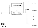
同期式または非同期式CDMA通信のための従来技術による線形マルチユーザ検出器のシステムブロック図を図4に示す。通信媒体特定受信機(図3に示す)から出力されるデータをサブチャネル推算装置、すなわちそれぞれのサブチャネル経由で送信される各シンボルのインパルス応答を推算するサブチャネル推算装置に供給する。線形検出器は、このインパルス応答推算値とサブチャネルの拡散符号とを用いてそのサブチャネルのデータを復調する。このデータをそれぞれのユーザ対応のサブチャネルデータ処理ブロックに出力する。
【0013】
実際のシステムにおいてK個のサブチャネルユーザを同時並行的に検出するためには、線形マルチユーザ検出器手法は、固定ゲートアレイ、マイクロプロセッサ、デジタルシグナルプロセッサDSPなどの形で実働化する。固定論理システムは処理速度を上げることを可能にするが、マイクロプロセッサ駆動システムではプログラミングの融通性が得られる。マルチユーザ検出を受け持ついずれの手段も、一連の数学的演算を実行する。この機能を説明するために、以下の変数で線形マルチユーザ検出器の構造と動作とを定義するのが通常である:
K=システム内の活性状態のユーザ/送信機の総数
Nc=データブロック内のチップ数。拡散率を変えた場合のすべてのユーザに共通の尺度としてチップ数が必要になる。チップ数は許容最大拡散率で割り切れる。同期式CDMAの場合、最大拡散率のユーザからのシンボルがデータのブロックを構成し得る。従って、Ncを最大拡散率と等しくなるまで減ずることができる
W=通信チャネルインパルス応答の長さをチップで表した値。一般にシステムの予め定められたパラメータである
Q(k)=ユーザkの拡散率。拡散率は、ユーザのデータのシンボルを拡散するのに用いるチップ数に等しい。システムには拡散率は既知であり、被受信データから推算する必要はない
Ns (k)=ユーザkが送ったシンボルの総数。Ns (k)=Nc/Q(k)

d(k)=ユーザkが送ったデータ(情報)。このデータは、ベクトルの形式で表され、一つのベクトルは一つの添字変数により示されるデータのアレイである。以下のベクトル演算および行列演算のために、すべてのベクトルは行ベクトルとして定義する。d(k)のn番目の要素は、k番目のユーザにより送信されるn番目のシンボルである
h(k)=ユーザkのサブチャネルが受けるインパルス応答をベクトルで表したもの。この量を受信機で推算する必要がある。サブチャネルのインパルス応答の受信機による推算値をh(k)と称する。ベクトルh(k)の要素は、通常は複素数であり、そのサブチャネルにより導入される振幅および位相の変動を表す
v(k)=ベクトルとして表したユーザkの拡散符号を線形マルチユーザ検出のために特定のシンボルを拡散する拡散符号の部分を含むベクトルとして考えると有用である。従って、ベクトルv(k,n)は、k番目のユーザにより送信されるn番目の符号の拡散に用いる拡散符号である。数学的には、これは(n-1)Q(k)+1≦i≦nQ(k)についてvi(k,n)=vi(k)と定義され、他のすべてのiに関して0となる。ただしiはベクトル要素のインデックスである
r(k)=ユーザkのデータを表すベクトルで、拡散系列v(k)により拡散され、そのユーザのサブチャネルh(k)経由で送信されてきたもの。ベクトルr(k)は、データのブロックが到着する期間中に実行されるチャネル観測結果を表す。ベクトルr(k)のi番目の要素は次の式で定義できる:
【式1】
【0014】
【式2】
【0015】
【0016】
図5は、従来技術による線形マルチユーザ検出器のシステムおよび方法を示す。サブチャネルインパルス応答推算値ベクトルh(k)と拡散符号v(k)とを用いて、各ユーザkについてのシステム送信応答行列を形成する。一つの行列は、二つの添字変数により表示した数のブロックであり、第1の添字変数を行インデックスとし、第2の添字変数を列インデックスとして長方形のグリッド状に配列する。
【0017】
ユーザkのシステム送信応答行列は、通常はA(k)で示す。第i行第n列の要素はAi,n (k)で示し、次のとおり定義する:
【式3】
【0018】
【0019】
A(k)の列は、次の形式をとる:
【式4】
【0020】
【式5】
【0021】
【式6】
【0022】
【0023】
各ユーザについてのシステム送信行列が形成されると、すべてのユーザについてのシステム送信行列を結合することによって総システム送信応答行列を次のとおり形成できる。
【0024】
【式7】
【0025】
![]()
【0026】
式4,5,6,7により組み立てた仮定の慣用マルチユーザ検出器についての総システム送信応答行列の一例は次のようになる:
【式8】
【0027】
【0028】
受信データrは、総システム送信応答行列A、すなわちyで示した整合フィルタ出力のベクトルを形成するための一連の整合フィルタ応答を表す総システム送信応答行列Aを用いて処理する。この整合フィルタ演算は、次のように定義される:
【式9】
【0029】
【0030】
零強制ブロック線形等化器(ZF−BLE)受信機は、O=AHAで特定される目的行列を有する線形受信機である。最小二乗平均誤差ブロック線形等化器(MMSE−BLE)受信機は、O=AHA+σ2Iで特定され目的行列を有する線形受信機である。ここで、σ2は受信データベクトルrのシンボルの各々に存在する雑音の分散であり、行列Iは単位行列と呼ばれる。単位行列は、正方形で対称形であり、その主対角線に1が、残りには0が配置された構成を有する。単位行列の大きさは、線形代数の法則に従い加算演算が有効になるよう選ぶ。
【0031】
相関解除装置(相関解除受信機)については、チャネル応答h(k)を無視し、拡散符号およびそれら符号の相互相関(干渉)特性のみを考慮することによって、行列Aを簡略化する。通常Rと呼ばれる相互相関行列は、一般に相関解除型の受信機について構築される。この行列は、上記のAの定義(すなわち各サブチャネルのチャネル応答がインパルス応答である)において、W=1およびhi (k)=1と仮定することにより構築することができる。これで相互相関行列Rは、ZF−BLE受信機について定義される目的行列Oとなる。相関解除装置は、より複雑なマルチユーザ検出受信機のサブプロセスとして働くことが多い。目的行列が生成されると、マルチユーザ検出器はO−1と示される形に行列を反転させる。
【0032】
次に目的行列の逆数に整合フィルタ出力ベクトルyを乗算して、データベクトルdの推算値、すなわちd(推算値)=O−1yを得る。目的行列の反転は、複雑で演算集中的なプロセスである。このプロセスを実行するために必要な演算の数は、行列Oの大きさの3乗の形で増加する。大半の非同期式CDMA受信機については、Oの大きさはきわめて大きくなり、そのために反転のプロセスは実行不可能となる。
【0033】
この制約を克服し、このシステムを実際に実現可能にするために、コレスキー(Cholesky)による数値法を用いる。コレスキー分解は、行列Oが帯行列の場合は、その行列Oを反転する際の演算の複雑度を大幅に軽減することができる。
【0034】
帯行列は、主対角軸から離れたいくつかの対角線上のみに非零値を含む正方行列である。少なくとも一つの非零要素を有する主対角線に隣接する非零対角線の数を帯域幅と呼ぶ。したがって、対称行列Mは、帯域幅pが:
【式10】
すべてのj>i+pについてmij=0
【0035】
の場合、帯行列であると言われる。ここで、mijは、Mの要素であり、iは行インデックス、jは列インデックスである。大きさがnで帯域幅pの帯行列については、コレスキー分解により、目的行列Oの反転に必要な数値演算の回数を行列の大きさの3乗から、帯域幅の2乗と行列の大きさとの積np2まで減らすことができる。
【0036】
上述のとおり、ZF−BLE受信機についての目的行列はO=AHAである。数値的な複雑さを説明するために、式6に示す総システム応答行列Aの目的行列Oは:
【式11】
【0037】
【0038】
図5に示す慣用の受信機において構築される目的行列Oは帯行列ではない。従って、行列Oを反転する際の演算の複雑性を軽減するためにコレスキー分解を効果的に用いることはできない。しかし、従来技術は、すべてのユーザが互いに等しい拡散率で送信する場合、目的行列Oの計算に先立ち総システム送信応答行列Aの再配列を実行して行列Oを帯行列に変えることができると開示している。このプロセスについてのシステムブロック図を図6に示す。
【0039】
行列Aの列再配列を計算するプロセスは、追加の情報なしにこの再配列を実行する。再配列により、行列を反転する際の演算上の複雑性を軽減する。検出手順が完了すると、ユーザベクトルdが計算され、逆向きの再配列プロセスが実行されて、ベクトルdのスクランブルを解除し、その元の形式に戻して更なる処理を行う。
【0040】
通常のCDMAシステムにおいては、再配列ずみの目的行列の帯域幅は、その元の大きさの少なくとも10倍小さい。従って、再配列ずみの総システム応答行列に基づいて目的行列でコレスキー分解を実行すると、処理時間が少なくとも100倍は節約される。しかし、従来技術は、活性状態のユーザ相互間で互いに異なる拡散率を用いた場合の再配列法は検討対象としていない。
【0041】
IEEE
Transactions on Vehicular Technology 第45巻第2号(1996年5月号)第276−287頁所載のKleinほか著の論文「符号分割多元接続チャネルにおけるマルチユーザ検出のための零強制および最小二乗平均誤差等化」はマルチユーザ検出の手法を開示している。それらの手法は零強制等化器にシステム応答行列を用い、データ再生のために最小二乗平均誤差等化を用いている。
【0042】
パーソナル、屋内および移動無線通信に関するIEEE国際シンポジウム論文集XX,XX,第3巻(1998年)第1340−1345頁所載のKarimiほか著の論文「近似コレスキー因数分解を用いたブロック利用共同検出への新規で効率的な解法」は近似コレスキー因数を用いた零強制線形等化器を開示している。このコレスキー因数はシステム応答行列を用いて導き出される。
【0043】
従って、互いに異なる拡散率を用いるときに反転ステップの数を軽減する方法を決定する必要がある。
【0044】
【発明の概要】
【0045】
本発明は、互いに異なる拡散率を有する同期式または非同期式のCDMAサブチャネルを演算の複雑性を軽減した形で検出し復号化するマルチユーザ検出器に関する。本発明のマルチユーザ検出器はZF−BLEやMMSEや相関解除検出器などコレスキー分解を利用する検出器と互換性をもち、数値演算を最小限に抑える。本システムおよび方法は、個々のユーザの応答特性を表すシステム送信応答行列の列を、受信データのあるブロックについての複数の整合フィルタ応答を表す総システム送信応答帯行列に配列する。本発明は、コレスキー分解との組合せにより並行整合フィルタ処理に先立つ所要の数学的演算の回数を減らす。
【0046】
したがって、本発明の目的は、各ユーザが互いに異なる拡散率を用いる場合に演算の複雑性を軽減してCDMAインタフェース経由送信中の複数のユーザを検出することである。
【0047】
本発明のもう一つの目的は、すべてのCDMAサブチャネル相互間で同一の拡散率を要することなくマルチユーザ検出器に既存の線形検出器を用いることである。
【0048】
本発明のさらにもう一つの目的は、反転前の複数の整合フィルタを表す行列の帯域幅を効率的に制限することである。
【0049】
本システムおよび方法の上記以外の目的および利点は、好適な実施例の詳細な説明を参照することにより当業者には明白になろう。
【0050】
【好適な実施例の説明】
【0051】
全図を通じて同じ構成要素を同じ参照番号で示した図面を参照して実施例を説明する。
【0052】
図7は、共用CDMAチャネル経由で送信を行う複数のユーザからの信号を受信ののち検出する本発明のマルチユーザ検出器17を示す。マルチユーザ検出器17は、種々のベクトル演算および行列演算を実行する複数の補助メモリ付きのプロセッサを備える。本発明の代替実施例は、種々のプロセッサの機能を実行する固定ゲートアレイおよびDSPを備える。また、検出器17は、ベクトルh(k)としてモデル化した個々のk個のサブチャネルインパルス応答推算値を入力して、サブチャネル自身のシンボルに起因する符号間干渉ISIとすべての受信データ信号について他のユーザのサブチャネルからのシンボルに起因する多重アクセス干渉MAIとを修正する第1の入力19と、離散的時間ブロック内に送信される全ユーザkからのデータを各ユーザのサブチャネルからの合成データを含む入力ベクトルrの形で入力する第2の入力21と、受信チャネルデータrから各ユーザkに関するユーザデータd(k)を出力ベクトルの形で出力する出力23とを備える。ユーザの総数Kと各ユーザk(k=1,2,3...K)についての拡散率Q(k)41は推算により既知である。
【0053】
合成ユーザデータrから特定のユーザについてのユーザデータd(k)を得るには、そのユーザデータを整合フィルタ25などによりフィルタ処理しなければならない。整合フィルタ25が送信前の信号を表すレベルの出力を生成するには、拡散ずみのパルス形状およびユーザサブチャネルのインパルス応答の組み合わせの複素共役値であるインパルス特性を必要とすることは当業者には認識されよう。フィルタ25への入力信号のうち所定の応答特性に一致しない入力信号は、より低い出力を生ずる。
【0054】
個々のサブチャネルkのインパルス応答推算値h(k)が第1のメモリ27に入力され、そこで同じユーザの拡散符号29(式3)と合成されてそのユーザについてのシステム送信応答推算値行列A(k)が生成される。本発明17の配列プロセッサ33は、すべての行列An (k)列の再配置を実行する。配列法99によると、各サブチャネルシステム送信応答行列A(k)は線形受信機に通常該当する式4で定義される列構造を備える必要がある。システム送信応答行列A(k)が式4に定義される形式でない場合は、配列プロセッサ33は式4で定義される構成に上記列をまず再配列する。本発明17では、システム送信応答行列A(k)全部を式7で定義される総システム送信応答行列Aに連結する必要はない。
【0055】
配列プロセッサ33は、図8に示す(一つの行列について)第1行のずれo(k) Tnおよび最下行のずれo(k) Bnを定義する各ベクトルbn (k)の台(式4)から零値要素の数に関する各システム送信応答行列A(1),A(2),A(3)...A(k)列を調べる。上述のとおり、各システム送信応答行列A(k)は、同数の行を有し、列数のみが変わる。図9に示すとおり、配列プロセッサ33は、それぞれの第1行のずれo( k) Tnおよび最下行のずれo(k) Bnに基づき、各システム送信応答行列A(k)の各列についてのインデックス値niを割り当てる。すなわち、第1行のずれが最小で最下行のずれが最大となる列から、第1行のずれが最大で最下行のずれが最小となる列までの昇順に割り当てる。
【0056】
一つの列が他の列よりも大きい第1行ずれおよび最下行ずれを有する二つの列が存在する場合であって、第1行ずれ相互間の差が最下行ずれ相互間の差よりも大きい場合は、第1行ずれの小さいほうの列に小さいほうのインデックスniを割り当てる。最下行ずれ相互間の差が第1行ずれ相互間の差よりも大きい場合は、最下行ずれの大きいほうの列に小さいほうのインデックスniを割り当てる。第1行ずれ相互間の差と最下行ずれ相互間の差とが等しい場合は、2つの列のいずれかに小さいほうのインデックスniを割り当てることもできる。配列プロセッサ33は、割り当てずみのインデックスniの順序に総システム送信応答行列A'を形成する。列インデックスniはメモリ33内に保持され、スクランブル解除プロセス45の期間中に用いられる。例として、式8に説明し図示した総システム送信応答行列A(1),A(2)を用いて、本発明17の配列法99が、以下に示す総システム送信応答行列Aを生成する。
【0057】
【式12】
【0058】
【0059】
上述の配列法99の実施例では、各システム送信応答行列A(1),A(2),A(3)...A(k)を調べ、第1行のずれo(k) Tnおよび最下行のずれo(k) Bnに付き各列を一つおきの列と比較する。各システム送信応答行列A(k)の特別の構成が与えられると、すなわち、各行列の列を左から右への進行に伴い第1行のずれが増加し最下行のずれが減少する順序に配列すると(式8,行列A(1)およびA(2)参照)、各システム送信応答行列A(k)を直接的に調べる必要なしに代替方法199を実行することができる。
【0060】
代替方法199を図10Aおよび図10Bに示す。互いに等しい拡散率を有するユーザに対応する(ステップ201)すべてのシステム送信応答行列A(k)をグループ化する(ステップ203)。各拡散率群gについて、全システム送信応答行列A(1),A(2),A(3)...A(k)からの列のすべてを格納できるプロセッサ33内に、メモリを割り当てる。拡散率群gは、拡散率の昇順に配列する。
【0061】
本発明199の性能を表すシステム例は、次のように割り当てた四つの互いに異なる拡散率Q(k)を有する七つのユーザを含む:
ユーザ1(Q(1))=8,ユーザ2(Q(2))=8,ユーザ3(Q(3))=8,ユーザ4(Q(4))=32,ユーザ5(Q(5))=16,ユーザ6(Q(6))=16,ユーザ7(Q(7))=4
本発明17のシステムおよび方法199を用いると、システム送信応答行列A(k)は、次のとおり拡散率群にグループ化される:
群1(拡散率4)A(7)
群2(拡散率8)A(1),A(2),A(3)
群3(拡散率16)A(5),A(6),
群4(拡散率32)A(4)
個々の拡散率群gは、少なくとも1つのシステム送信応答行列A(k)を含む。ここで、各行列A(k)には1からL(g)まで任意のインデックスを付ける。各拡散率群gには、拡散率の大きさの昇順にインデックスを付ける。
【0062】
各拡散率群の中では、関連のシステム送信応答行列A(k)の列を共通の拡散率群送信応答行列AG (g)に組み立てる。ここで、g=1,2,3,...Gである(ステップ205)。図11に示すとおり、方法199はインデックス1のシステム送信応答行列の第1列をAG (g)の第1空白列に複製し、インデックス2のシステム送信応答行列の第1列をAG (g)の第2空白列に複製し、それぞれの拡散率群g内の残りのシステム送信応答行列全部について第1列すべてを複製するまで上記複製を続ける。方法199は、それぞれの拡散率群AG (g)の各行列A(k)について第2列、第3列などの複製を進める。
【0063】
拡散率群g内のすべての行列は拡散率が互いに同じであるので同数の列を有する。従って、構築された拡散率群送信応答行列AG (g)は、一つの関連システム送信応答行列A(k)内の列数のL(g)倍の列を有することになる。互いに等しい拡散率については、群毎に各システム送信応答行列に適用される配列方法は総システム送信応答行列Aを構築する従来技術と同様である。
【0064】
可変拡散率を許容する総システム送信応答行列A'を構築するには、最小拡散率の拡散率群送信応答行列AG (g)を第1列すなわちAG (g)の第1列から始めてA'の第1割当列までメモリ33a内に順次複製する(ステップ207)。最小拡散率の拡散率群送信応答行列AG (g)が最大列数を有する。それ以外の拡散率の拡散率群送信応答行列の列はこの基底行列A'に挿入される。
【0065】
システム拡散率が相互に整数倍の関係にある場合(ステップ209)は、プロセッサ33は、任意の順序で残りの拡散率群送信行列AG (g)を考慮することにより(ステップ209)、総システム送信行列A'を構築する(ステップ211)。各拡散率群送信行列AG (g)について、プロセッサ33は、列配置基準インデックスmを導く:
【式13】
【0066】
【0067】
列配置インデックスmを用いるために、最小拡散率の拡散率群行列を構成するシステム送信応答行列の総数L(1)を用いてA'の中の基準位置を導く(ステップ215)。
【0068】
【式14】
【0069】
【式15】
L(g) x (n-1) +1〜L(g) x n
【0070】
プロセッサ33は、式15で定義される列集合をAG (g)から複製し、それを図12の式14で定義される基準位置を有するAG (1)の列の後で基底行列A'内に挿入する(ステップ219)。検討中の拡散率群行列の残りの列も同様に複製され基底行列A'内に挿入される。一つの拡散率群行列のすべての列を配置すると、プロセッサ33は次の拡散率群行列AG (g)を選択し(ステップ223)、上記の方法を実行する。式13、14および15により、残りの拡散率群送信行列AG (g)からi番目の列を類似の台を有するm番目の列の後でA'内に配置することができる(ステップ225)。
【0071】
システム拡散率が相互に整数の関係にない場合は、式13の右辺は整数にならない。その場合、プロセッサ33は式13の解をその値よりも大きい最寄りの整数、あるいはそれより小さい最寄りの整数に切り上げまたは切り下げる(ステップ213)。切上げ/切下げる方向がシステム全体の性能に及ぼす影響は無視できる程度である。残りの群システム送信行列AG (g)を検討する順序は、システム性能に多少影響する。拡散率に関する推測ができる場合は、それを用いて最適の順序を予め選ぶことができる。
【0072】
上述の配列法を用いると、拡散率が互いに整数倍の関係にある場合については、次式で制約される行列帯域幅Bを得ることができる:
【式16】
【0073】
【0074】
本発明17がもたらす改良は送信シンボルの数の増加とともにさらに高く評価される。システムが16,000チップ(第1のユーザに対して800シンボル、第2のユーザに対して400シンボル)を送ると、行列AHAの帯域幅は約800となる。配列法99を用いて総システム応答行列Aを生成すると、A’HA’の帯域幅は4に留まる。すなわち、帯域幅(式16)が送信シンボル数に左右されないからである。目的行列Oのすべての要素を導いたあと反転41を実行する。行列の反転の複雑性はその帯域幅の2乗に比例するので、本発明17は演算の複雑性を約(800/4)2=2002=40,000分の1に低減する。
【0075】
総システム送信応答行列A'は整合フィルタ25に応答特性を与える。システム応答行列A'の各列は、特定のシンボルの応答特性を表すベクトルである。受信データベクトルrが整合フィルタ25に入力され、そこで総システム送信応答行列A'の各応答特性と整合されて、整合フィルタ出力ベクトルyを生成する。出力ベクトルyの各要素は、所定のユーザが送信する特定のシンボルの予備推算値に対応する。整合フィルタ25の出力ベクトルyを反転した目的行列Oと共に乗算器43に加える。整合フィルタ25の出力ベクトルyおよび反転された目的行列Oの両方を乗算し、ユーザデータベクトルdを生ずる。ユーザデータベクトルdは、離散的時間ブロックの期間中にすべてのユーザが送信したすべてのデータを含む。目的行列Oおよび整合フィルタ25の出力は、総システム応答行列A'に基づくので、ユーザデータベクトルdはスクランブル解除しなければならない。スクランブル解除のプロセス149は、配列方法99,199の逆である。
【0076】
スクランブル解除器45は、配列方法99または199の実行中に実施される列の再割当に基づき、ユーザデータベクトルdの各要素を再配列する。データベクトルdの要素は、総送信応答行列Aにより決まる順序と同じ1,9,2,3,10,4,5,11,6,7,12,8が縦に転置された順序である。スクランブル解除器45は、同じ大きさのメモリ領域を割り当て、各ベクトル要素を順次式にすなわち1〜12の順に割り当てる。ユーザデータベクトルdのスクランブル解除したあと(149)、ユーザデータを出力(23)してさらに処理する。
【0077】
本発明を好適な実施例と関連づけて上に述べてきたが、添付の請求項に示した本発明の範囲内の上記以外の変形も当業者には自明であろう。
【図面の簡単な説明】
【0078】
【図1】 従来技術による多元接続通信システムの簡略化したブロック図。
【図2】 従来技術によるCDMA通信システムの簡略化したブロック図。
【図3】 マルチユーザ検出を行う従来技術によるCDMA受信機の簡略化したブロック図。
【図4】 従来技術によるマルチユーザ検出器の簡略化したブロック図。
【図5】 従来技術による線形マルチユーザ検出器のブロック図。
【図6】 コレスキー分解を用いた従来技術による線形マルチユーザ検出器のブロック図。
【図7】 本発明の線形マルチユーザ検出器のブロック図。
【図8】 システム送信応答行列A(k)の第1列と最下列のずれを示す図。
【図9】 行列の列インデックス値割当てを示す図。
【図10A】 本発明を実行する代替の方法の流れ図。
【図10B】 本発明を実行する代替の方法の流れ図。
【図11】 拡散率群行列AG (g)を構築するステップを示す図。
【図12】 本発明によるA'行列の構築のステップを示す図。
【符号の説明】
【0079】
19 チャネルインパルス応答推算値h(1),・・・h(k)を入力する
21 受信ベクトルrを入力する
23 ユーザデータd(k)を出力する
25 AHによりrを整合フィルタ処理し、整合フィルタ出力のベクトルであるyを生成する
27 システム応答行列A(n) (k)を構築する
29 拡散符号
31 総システム送信行列Aを構築する
33 再配列プロセッサ
37 Aの列を再配列する
39 A'に基づき目的行列Oを形成する
41 Oを反転する
41 拡散率Q(k)
43 yにOの逆数を乗算して、推算されたユーザデータベクトルdを生成する
45 ユーザデータベクトルdのスクランブルを解除し、適切なユーザに出力する
201 開始
203 システム送信応答行列を互いに等しい拡散率に従ってグループ化する
205 すべての拡散率群について拡散率群行列AG (g)を組み立てる
207 最小拡散率群行列を用いて基底A'行列を形成する
209 残りの拡散率行列から検討対象の行列を選択する
211 列配置基準を導く(式13)
213 基準が整数?
215 端数切り上げ/切り下げ
217 基準位置を導く(式14)
219 基準位置列後の検討対象の拡散率群行列から列集合を導く
221 すべての列を検討対象の拡散率行列から複製した?
223 すべての拡散率行列を処理した?
225 終了[0001]
(Field of Invention)
The present invention relates generally to multiple access digital communication systems. More particularly, the present invention relates to a multi-user detector system and method for simultaneously receiving data from a plurality of users having different spreading factors.
[0002]
(Description of related technology)
A multiple access communication system allows multiple users to access the same communication medium to send or receive information. This medium is constituted, for example, by a network cable of a local area network LAN, a copper wire of a conventional telephone system or a wireless interface for wireless communication.
[0003]
A multiple access communication system according to the prior art is shown in FIG. The communication medium is called a communication channel. Frequency division multiple access FDMA, time division multiple access TDMA, carrier sense multiple access CSMA, code division multiple access CDMA, and other communication technologies allow two or more users to access the same communication medium. These techniques can be combined to form various complex multiple access techniques. For example, the time division duplex TDD mode of the third generation W-CDMA technology standard proposal is a combination of TDMA and CDMA.
[0004]
An example of a prior art CDMA communication system is shown in FIG. CDMA is a communication technique for transmitting data by expanding a band (spread spectrum) by modulating a signal to be transmitted with a pseudo-noise signal. The data signal to be transmitted has a bandwidth of only a few thousand hertz distributed over one frequency band spanning millions of hertz. The communication channel is used in parallel by K different subchannels. For each subchannel, all other subchannels appear to be interference.
[0005]
As shown in the figure, one subchannel of a certain bandwidth is mixed with a specific spreading code, that is, a specific spreading code that repeats a predetermined pattern generated by a wide bandwidth pseudo-noise (pn) sequence generator. These user-specific spreading codes are usually quasi-orthogonal codes in order to make cross-correlation between spreading codes close to zero. Modulate with a pn sequence to generate a digital spread spectrum signal. Next, the carrier wave signal is modulated with the digital spread spectrum signal and transmitted via a transmission medium. The receiver demodulates the transmission signal and extracts the digital spread spectrum signal. The transmitted data is reproduced by correlating with the pn sequence that matches the transmission side. If the spreading codes are orthogonal to each other, the received signal shows a correlation with a specific user signal related to the specific spreading code, emphasizes only the desired user signal related to the specific spreading code, and otherwise Other signals associated with all users are not highlighted.
[0006]
Each value of the spreading code is called a chip and has a chip speed equal to or higher than the data speed. The ratio between the chip rate and the subchannel data rate is called the spreading factor.
[0007]
In order to widen the range of possible values of the data signal, symbols representing three or more binary values are used. The ternary symbol and the quaternary symbol take a ternary value and a quaternary value, respectively. Since the bit content of each symbol determines a unique pulse shape based on the concept of symbols, the amount of information transmission can be further increased. Depending on the number of symbols used, there are the same number of unique pulses or waveforms. Information at the transmission source is converted into symbols, modulated with the symbols, transmitted via the subchannel, and demodulated at the transmission destination.
[0008]
The spreading code in a CDMA system is chosen to minimize interference between the desired subchannel and all other subchannels. Therefore, the standard method for demodulating a desired subchannel is a method in which all other subchannels are treated as interference similar to interference appearing in the communication medium. Receivers designed to be compatible with this signal processing are single-user matched filter receivers and rake receivers.
[0009]
Since different subchannels interfere with each other in some way, another method is to demodulate all subchannels at the receiver. The receiver can receive all of the users by executing in parallel the decoding algorithm for each of the users being transmitted in parallel. This method is called multiuser detection. Multi-user detection can greatly improve performance compared to a single user receiver.
[0010]
Referring to FIG. 3, a system block diagram of a prior art CDMA receiver using a multiuser detector is shown. As will be apparent to those skilled in the art, the receiver may include functions such as radio frequency RF down-conversion and associated filtering for radio frequency channels, analog-to-digital conversion or optical signal demodulation for a particular communication medium. . The output of the receiver is an analog or digital processed signal containing the combined spread signal of all active subchannels. The multi-user detector performs multi-user detection and outputs a plurality of signals corresponding to each active subchannel. All or a smaller number of subchannels can be processed.
[0011]
The most preferred multi-user detector is a computationally intensive device that performs many complex operations, which is difficult to implement economically. In order to minimize costs, suboptimal multi-user detectors such as linear detectors with reduced computational complexity have been developed as a compromise close to optimal detector performance. The linear detector includes a decorrelator, a least mean square error MMSE detector, and a zero forced block linear equalizer ZF-BLE.
[0012]
A system block diagram of a prior art linear multiuser detector for synchronous or asynchronous CDMA communication is shown in FIG. Data output from the communication medium specific receiver (shown in FIG. 3) is supplied to a subchannel estimation device, that is, a subchannel estimation device that estimates an impulse response of each symbol transmitted via each subchannel. The linear detector demodulates the subchannel data using the impulse response estimated value and the subchannel spreading code. This data is output to the subchannel data processing block corresponding to each user.
[0013]
In order to detect K subchannel users in parallel in a real system, the linear multiuser detector approach is implemented in the form of a fixed gate array, a microprocessor, a digital signal processor DSP, etc. While fixed logic systems allow for increased processing speeds, microprocessor-driven systems offer programming flexibility. Any means responsible for multi-user detection performs a series of mathematical operations. To illustrate this functionality, it is common to define the structure and operation of a linear multiuser detector with the following variables:
K = total number of active users / transmitters in the system
Nc= Number of chips in the data block. The number of chips is necessary as a common measure for all users when the spreading factor is changed. The number of chips is divisible by the maximum allowable spreading factor. In the case of synchronous CDMA, symbols from users with the highest spreading factor may constitute a block of data. Therefore, NcCan be reduced to be equal to the maximum diffusivity
W = a value representing the length of the communication channel impulse response in chips. Generally a predetermined parameter of the system
Q(K)= Spreading factor of user k. The spreading factor is equal to the number of chips used to spread the user data symbols. The system has a known spreading factor and does not need to be estimated from received data
Ns (K)= Total number of symbols sent by user k. Ns (K)= Nc/ Q(K)
d(K)= Data (information) sent by user k. This data is represented in the form of a vector, where one vector is an array of data indicated by one subscript variable. For the following vector and matrix operations, all vectors are defined as row vectors. d(K)The n th element of is the n th symbol transmitted by the k th user
h(K)= The vector representing the impulse response received by the subchannel of user k. This amount needs to be estimated at the receiver. The estimated value of the subchannel impulse response by the receiver is h.(K)Called. Vector h(K)The elements of are usually complex and represent the amplitude and phase variations introduced by that subchannel
v(K)= It is useful to think of the spreading code of user k expressed as a vector as a vector containing the portion of the spreading code that spreads a particular symbol for linear multiuser detection. Therefore, the vector v(K, n)Is a spreading code used for spreading the nth code transmitted by the kth user. Mathematically, this is (n-1) Q(K)+ 1 ≦ i ≦ nQ(K)About vi(K, n)= Vi(K)And is 0 for all other i. Where i is the index of the vector element
r(K)= Vector representing user k's data, spreading sequence v(K)The user's subchannel h(K)What has been sent via. Vector r(K)Represents the channel observations performed during the period when the block of data arrives. Vector r(K)The i th element of can be defined as:
[Formula 1]
[0014]
[Formula 2]
[0015]
[0016]
FIG. 5 illustrates a prior art linear multiuser detector system and method. Subchannel impulse response estimation value vector h(K)And spreading code v(K)Are used to form a system transmission response matrix for each user k. One matrix is the number of blocks indicated by two subscript variables, and is arranged in a rectangular grid with the first subscript variable as a row index and the second subscript variable as a column index.
[0017]
The system transmission response matrix of user k is usually A(K)It shows with. The element in the i-th row and the n-th column is Ai, n (K)And define it as follows:
[Formula 3]
[0018]
[0019]
A(K)The sequence of takes the following form:
[Formula 4]
[0020]
[Formula 5]
[0021]
[Formula 6]
[0022]
[0023]
Once the system transmission matrix for each user is formed, the total system transmission response matrix can be formed as follows by combining the system transmission matrices for all users:
[0024]
[Formula 7]
[0025]
![]()
[0026]
An example of the total system transmission response matrix for a hypothetical conventional multiuser detector constructed according to
[Formula 8]
[0027]
[0028]
The received data r is processed using a total system transmission response matrix A, that is, a total system transmission response matrix A representing a series of matched filter responses to form a vector of matched filter outputs denoted y. This matched filter operation is defined as follows:
[Formula 9]
[0029]
[0030]
Zero forced block linear equalizer (ZF-BLE) receiver is O = AHA linear receiver having an objective matrix specified by A. The least mean square error block linear equalizer (MMSE-BLE) receiver is O = AHA + σ2A linear receiver identified by I and having an objective matrix. Where σ2Is the variance of noise present in each symbol of the received data vector r, and the matrix I is called a unit matrix. The unit matrix is square and symmetrical, and has a configuration in which 1 is arranged on the main diagonal and 0 is arranged in the rest. The size of the identity matrix is chosen so that the addition operation is valid according to the laws of linear algebra.
[0031]
For the decorrelation device (decorrelation receiver), the channel response h(K)And the matrix A is simplified by considering only the spreading codes and the cross-correlation (interference) characteristics of those codes. A cross-correlation matrix, usually called R, is generally constructed for a decorrelation type receiver. This matrix is W = 1 and h in the definition of A above (ie, the channel response of each subchannel is an impulse response).i (K)Can be constructed by assuming = 1. Thus, the cross-correlation matrix R becomes the objective matrix O defined for the ZF-BLE receiver. The decorrelator often serves as a sub-process for more complex multi-user detection receivers. Once the objective matrix is generated, the multiuser detector is O-1Invert the matrix to the form
[0032]
Next, the reciprocal of the objective matrix is multiplied by the matched filter output vector y, and the estimated value of the data vector d, that is, d (estimated value) = O-1get y. Inversion of the objective matrix is a complex and computationally intensive process. The number of operations required to perform this process increases in the form of the cube of the size of the matrix O. For most asynchronous CDMA receivers, the magnitude of O becomes very large, which makes the inversion process infeasible.
[0033]
In order to overcome this limitation and make this system practically feasible, a numerical method by Cholesky is used. In the case of the Cholesky decomposition, when the matrix O is a band matrix, the computational complexity when the matrix O is inverted can be greatly reduced.
[0034]
A band matrix is a square matrix containing non-zero values only on some diagonals away from the main diagonal axis. The number of non-zero diagonals adjacent to the main diagonal having at least one non-zero element is called bandwidth. Thus, the symmetric matrix M has a bandwidth p:
[Formula 10]
M for all j> i + pij= 0
[0035]
Is said to be a banded matrix. Where mijAre elements of M, i is a row index, and j is a column index. For a band matrix of size n and bandwidth p, the number of numerical operations required for inversion of the target matrix O is changed from the cube of the matrix size to the square of the bandwidth and the matrix size by Cholesky decomposition. Product np2Can be reduced to.
[0036]
As mentioned above, the objective matrix for ZF-BLE receiver is O = AHA. To explain the numerical complexity, the objective matrix O of the total system response matrix A shown in Equation 6 is:
[Formula 11]
[0037]
[0038]
The objective matrix O constructed in the conventional receiver shown in FIG. 5 is not a band matrix. Therefore, Cholesky decomposition cannot be used effectively in order to reduce the complexity of the operation when inverting the matrix O. However, according to the conventional technique, when all users transmit with the same spreading factor, the rearrangement of the total system transmission response matrix A can be performed prior to the calculation of the target matrix O to change the matrix O into a band matrix. Disclosure. A system block diagram for this process is shown in FIG.
[0039]
The process of calculating the column rearrangement of matrix A performs this rearrangement without additional information. Reordering reduces the computational complexity of inverting the matrix. When the detection procedure is complete, the user vector d is calculated and a reverse reordering process is performed to unscramble the vector d and return it to its original form for further processing.
[0040]
In a typical CDMA system, the bandwidth of the rearranged target matrix is at least 10 times smaller than its original size. Therefore, performing Cholesky decomposition on the target matrix based on the rearranged total system response matrix saves processing time by at least 100 times. However, the conventional technique does not consider the rearrangement method in the case where different diffusion rates are used between users in the active state.
[0041]
IEEE
Transactions on Vehicular Technology, Vol. 45, No. 2 (May 1996), pages 276-287, Klein et al. “Equalization” discloses a technique for multi-user detection. These methods use a system response matrix for a zero-forced equalizer and use least mean square error equalization for data recovery.
[0042]
IEEE International Symposium on Personal, Indoor and Mobile Radio Communications XX, XX, Volume 3 (1998), pages 1340-1345, paper by Karimi et al. A new and efficient solution to "discloses a zero-forced linear equalizer using approximate Cholesky factors. This Cholesky factor is derived using the system response matrix.
[0043]
Therefore, it is necessary to determine a method for reducing the number of inversion steps when using different diffusion rates.
[0044]
SUMMARY OF THE INVENTION
[0045]
The present invention relates to a multi-user detector that detects and decodes synchronous or asynchronous CDMA subchannels having different spreading factors with reduced computational complexity. The multi-user detector of the present invention is compatible with detectors that use Cholesky decomposition, such as ZF-BLE, MMSE, and de-correlation detectors, and minimizes numerical operations. The system and method arranges the columns of the system transmission response matrix representing the response characteristics of individual users into a total system transmission response band matrix representing a plurality of matched filter responses for a block of received data. The present invention reduces the number of mathematical operations required prior to parallel matched filter processing in combination with Cholesky decomposition.
[0046]
Accordingly, an object of the present invention is to detect a plurality of users who are transmitting via a CDMA interface while reducing the complexity of calculation when each user uses a different spreading factor.
[0047]
Another object of the present invention is to use existing linear detectors for multi-user detectors without requiring the same spreading factor between all CDMA subchannels.
[0048]
Yet another object of the present invention is to efficiently limit the bandwidth of a matrix representing a plurality of matched filters before inversion.
[0049]
Other objects and advantages of the present system and method will become apparent to those skilled in the art upon reference to the detailed description of the preferred embodiment.
[0050]
DESCRIPTION OF PREFERRED EMBODIMENTS
[0051]
Embodiments will be described with reference to the drawings, in which the same constituent elements are designated by the same reference numerals throughout the drawings.
[0052]
FIG. 7 shows a
[0053]
User data d for a specific user from the synthesized user data r(K)To obtain the user data, the user data must be filtered by the matched
[0054]
Impulse response estimate h for each subchannel k(K)Is input to the
[0055]
The
[0056]
There are two columns with a first row shift and a bottom row shift where one column is larger than the other columns, and the difference between the first row shifts is greater than the difference between the bottom row shifts The smaller index n in the smaller column of the first row shiftiAssign. If the difference between the bottom row deviations is greater than the difference between the first row deviations, the smaller index n in the column with the largest bottom row deviation.iAssign. If the difference between the first row shifts and the difference between the bottom row shifts are equal, the smaller index n in one of the two columnsiCan also be assigned. The
[0057]
[Formula 12]
[0058]
[0059]
In the above-described example of the array method 99, each system transmission response matrix A(1), A(2), A(3). . . A(K)Check the first line o(K) TnAnd bottom line shift o(K) BnCompare each column with every other column. Each system transmission response matrix A(K)That is, if the columns of each matrix are arranged in the order in which the shift of the first row increases and the shift of the bottom row decreases with progression from left to right (Equation 8, matrix A(1)And A(2)See), each system transmission response matrix A(K)Alternative method 199 can be performed without the need to look up directly.
[0060]
An
[0061]
An example system representing the performance of the
User 1 (Q(1)) = 8, User 2 (Q(2)) = 8, User 3 (Q(3)) = 8, user 4 (Q(4)) = 32, user 5 (Q(5)) = 16, user 6 (Q(6)) = 16, user 7 (Q(7)) = 4
Using the system and
Group 1 (diffusivity 4) A(7)
Group 2 (diffusivity 8) A(1), A(2), A(3)
Group 3 (diffusivity 16) A(5), A(6),
Group 4 (diffusivity 32) A(4)
Each spreading factor group g is composed of at least one system transmission response matrix A(K)including. Where each
[0062]
Within each spreading factor group, the associated system transmission response matrix A(K)Is a common spreading factor group transmission response matrix AG (G)Assemble. Here, g = 1, 2, 3,... G (step 205). As shown in FIG. 11, the
[0063]
Since all the matrices in the spreading factor group g have the same spreading factor, they have the same number of columns. Therefore, the constructed spreading factor group transmission response matrix AG (G)Is one related system transmission response matrix A(K)L of the number of columns in(G)Will have double columns. For spreading factors that are equal to each other, the arrangement method applied to each system transmission response matrix for each group is the same as in the prior art for constructing the total system transmission response matrix A.
[0064]
To construct a total system transmission response matrix A ′ that allows a variable spreading factor, a spreading factor group transmission response matrix A with a minimum spreading factorG (G)In the first column, AG (G)Are replicated sequentially in the memory 33a from the first column to the first assigned column of A ′ (step 207). Spreading factor group transmission response matrix A with minimum spreading factorG (G)Has the maximum number of columns. The columns of the spreading factor group transmission response matrix with other spreading factors are inserted into this base matrix A ′.
[0065]
When the system spreading factor is an integer multiple of each other (step 209), the
[Formula 13]
[0066]
[0067]
In order to use the column arrangement index m, the total number L of system transmission response matrices constituting the spreading factor group matrix of the minimum spreading factor(1)Is used to derive the reference position in A ′ (step 215).
[0068]
[Formula 14]
[0069]
[Formula 15]
L(G) x (n-1) +1 to L(G) x n
[0070]
The
[0071]
If the system spreading factors are not in an integer relationship with each other, the right side of
[0072]
Using the arrangement method described above, the matrix bandwidth B constrained by the following equation can be obtained for spreading factors that are integer multiples of each other:
[Formula 16]
[0073]
[0074]
The improvement brought about by the
[0075]
The total system transmission response matrix A ′ gives response characteristics to the matched
[0076]
The descrambling
[0077]
While the invention has been described above in connection with a preferred embodiment, other modifications within the scope of the invention as set forth in the appended claims will be apparent to those skilled in the art.
[Brief description of the drawings]
[0078]
FIG. 1 is a simplified block diagram of a multiple access communication system according to the prior art.
FIG. 2 is a simplified block diagram of a CDMA communication system according to the prior art.
FIG. 3 is a simplified block diagram of a prior art CDMA receiver that performs multi-user detection.
FIG. 4 is a simplified block diagram of a multi-user detector according to the prior art.
FIG. 5 is a block diagram of a linear multiuser detector according to the prior art.
FIG. 6 is a block diagram of a prior art linear multiuser detector using Cholesky decomposition.
FIG. 7 is a block diagram of a linear multiuser detector of the present invention.
FIG. 8 System transmission response matrix A(K)The figure which shows the shift | offset | difference of the 1st row | line and the lowest row of.
FIG. 9 is a diagram showing column index value assignment of a matrix.
FIG. 10A is a flow diagram of an alternative method of implementing the invention.
FIG. 10B is a flow diagram of an alternative method of implementing the invention.
FIG. 11: Spreading factor group matrix AG (G)The figure which shows the step which builds.
FIG. 12 is a diagram showing steps for constructing an A ′ matrix according to the present invention.
[Explanation of symbols]
[0079]
19 Channel impulse response estimate h(1), ... h(K)Enter
21 Input receive vector r
23 User data d(K)Output
25 AHTo match-filter r and generate a matched-filter output vector y
27 System Response Matrix A(N) (K)Build
29 Spreading code
31 Construct total system transmission matrix A
33 Rearrangement processor
Rearrange the 37 A row
39 Form object matrix O based on A '
Invert 41 O
41 Diffusivity Q(K)
43 Multiply y by the reciprocal of O to generate the estimated user data vector d
45 Unscramble user data vector d and output to appropriate user
201 start
203 Group system transmission response matrices according to equal spreading factor
205 Spreading factor matrix A for all spreading factorsG (G)Assemble
207 Form basis A ′ matrix using minimum diffusivity group matrix
209 Select the matrix to be examined from the remaining spreading factor matrices
211 Deriving column placement criteria (Equation 13)
213 Is the standard an integer?
215 Round up / down
217 Deriving the reference position (Formula 14)
219 Deriving column set from spreading factor group matrix to be examined after reference position sequence
221 Did all columns replicate from the diffusivity matrix under consideration?
223 Have you processed all the diffusivity matrices?
225 End
Claims (30)
前記システム応答行列を互いに対応のデータ信号について同じ拡散率を有するグループにグループ化する過程(203)と、
前記グループの各々につき、そのグループの中のシステム応答行列すべての列を含むグループ応答行列を構築する過程(205)と、
最低拡散率を有するグループを除外した前記グループの各々につき、そのグループの列を最低拡散率グループに順次的に挿入して総システム応答行列とする過程(209−223)と、
前記受信したデータ信号および前記総システム応答行列を用いて前記データ信号のデータを算定する過程(25、41、43、45、23)と
を含むことを特徴とする方法。A method for reproducing a plurality of data signals transmitted in a wireless code division multiple access communication system, i.e., data signals having different spreading factors, receiving the plurality of data signals (21) and receiving the received data In the data signal reproduction method, an impulse response is calculated for each of the signals (19), and for each of the data signals, a system response matrix is derived using the impulse response of the data signal and the spreading code (29) of the data signal (27). ,
Grouping (203) the system response matrix into groups having the same spreading factor for corresponding data signals;
Constructing (205) a group response matrix for each of the groups, including a column of all system response matrices in the group;
For each of the groups excluding the group having the lowest spreading factor, a step of sequentially inserting the group column into the lowest spreading factor group to obtain a total system response matrix (209-223);
Calculating the data signal using the received data signal and the total system response matrix (25, 41, 43, 45, 23).
前記システム応答行列を互いに対応のデータ信号について同じ拡散率を有するグループにグループ化する手段(33)と、
前記グループの各々につき、そのグループの中のシステム応答行列すべての列を含むグループ応答行列を構築する手段(33)と、
最低拡散率を有するグループを除外した前記グループの各々につき、そのグループの列を最低拡散率グループに順次的に挿入して総システム応答行列とする手段(33)と、
前記受信したデータ信号および前記総システム応答行列を用いて前記データ信号のデータを算定する手段(33)と
を含むことを特徴とする受信機。A receiver for reproducing a plurality of data signals transmitted in a wireless code division multiple access communication system, that is, a data signal having a spreading factor different from each other, receiving the plurality of data signals, and receiving the received data signals In a receiver that calculates an impulse response for each and derives a system response matrix using the impulse response of the data signal and the spreading code of the data signal for each of the data signals,
Means (33) for grouping said system response matrices into groups having the same spreading factor for mutually corresponding data signals;
Means (33) for constructing a group response matrix comprising for each of said groups all columns of the system response matrix in that group;
Means (33) for each of the groups excluding the group with the lowest spreading factor to form a total system response matrix by sequentially inserting the columns of the group into the lowest spreading factor group;
Means (33) for calculating data of said data signal using said received data signal and said total system response matrix.
前記システム応答行列を互いに対応のデータ信号について同じ拡散率を有するグループにグループ化し、前記グループの各々につきそのグループの中のシステム応答行列すべての列を含むグループ応答行列を構築し、最低拡散率を有するグループを除外した前記グループの各々につきそのグループの列を最低拡散率グループに順次的に挿入して総システム応答行列とする再配列プロセッサ(33)を含み、
前記受信したデータ信号および前記総システム応答行列を用いて前記データ信号のデータを算定する
ことを特徴とする受信機。A receiver for reproducing a plurality of data signals transmitted in a wireless code division multiple access communication system, that is, a data signal having a spreading factor different from each other, receiving the plurality of data signals (21) and receiving them For each data signal, the impulse response is calculated by the channel estimator (19), and for each data signal, the linear data detector uses the impulse response of the data signal and the spreading code (29) of the data signal to obtain a system response matrix. (27) In the receiver,
Grouping the system response matrix into groups having the same spreading factor for data signals corresponding to each other, constructing a group response matrix including columns of all system response matrices in the group for each of the groups, and setting the lowest spreading factor to Including a rearrangement processor (33) for each of the groups excluding having a group that is sequentially inserted into the lowest spreading factor group to form a total system response matrix;
A receiver for calculating data of the data signal using the received data signal and the total system response matrix.
Applications Claiming Priority (3)
| Application Number | Priority Date | Filing Date | Title |
|---|---|---|---|
| US15498599P | 1999-09-21 | 1999-09-21 | |
| US60/154,985 | 1999-09-21 | ||
| PCT/US2000/002621 WO2001022610A1 (en) | 1999-09-21 | 2000-02-02 | Multiuser detector for variable spreading factors |
Related Child Applications (1)
| Application Number | Title | Priority Date | Filing Date |
|---|---|---|---|
| JP2007223219A Division JP2008017520A (en) | 1999-09-21 | 2007-08-29 | Multiuser detector for variable spreaing factors |
Publications (3)
| Publication Number | Publication Date |
|---|---|
| JP2003510884A JP2003510884A (en) | 2003-03-18 |
| JP2003510884A5 JP2003510884A5 (en) | 2005-09-02 |
| JP4365063B2 true JP4365063B2 (en) | 2009-11-18 |
Family
ID=22553662
Family Applications (2)
| Application Number | Title | Priority Date | Filing Date |
|---|---|---|---|
| JP2001525863A Expired - Fee Related JP4365063B2 (en) | 1999-09-21 | 2000-02-02 | Multi-user detector adapted to variable spreading factor |
| JP2007223219A Pending JP2008017520A (en) | 1999-09-21 | 2007-08-29 | Multiuser detector for variable spreaing factors |
Family Applications After (1)
| Application Number | Title | Priority Date | Filing Date |
|---|---|---|---|
| JP2007223219A Pending JP2008017520A (en) | 1999-09-21 | 2007-08-29 | Multiuser detector for variable spreaing factors |
Country Status (19)
| Country | Link |
|---|---|
| US (2) | US7136369B2 (en) |
| EP (1) | EP1214796B1 (en) |
| JP (2) | JP4365063B2 (en) |
| KR (3) | KR20050039883A (en) |
| CN (3) | CN1201499C (en) |
| AT (1) | ATE287149T1 (en) |
| AU (1) | AU2636500A (en) |
| BR (1) | BR0014206A (en) |
| CA (1) | CA2385082C (en) |
| DE (2) | DE60017424T2 (en) |
| DK (1) | DK1214796T3 (en) |
| ES (1) | ES2234566T3 (en) |
| HK (1) | HK1046338B (en) |
| IL (4) | IL148607A0 (en) |
| MX (1) | MXPA02002819A (en) |
| NO (2) | NO325841B1 (en) |
| SG (1) | SG152901A1 (en) |
| TW (1) | TW493321B (en) |
| WO (1) | WO2001022610A1 (en) |
Cited By (1)
| Publication number | Priority date | Publication date | Assignee | Title |
|---|---|---|---|---|
| JP2008017520A (en) * | 1999-09-21 | 2008-01-24 | Interdigital Technol Corp | Multiuser detector for variable spreaing factors |
Families Citing this family (39)
| Publication number | Priority date | Publication date | Assignee | Title |
|---|---|---|---|---|
| US6714527B2 (en) | 1999-09-21 | 2004-03-30 | Interdigital Techology Corporation | Multiuser detector for variable spreading factors |
| KR100383594B1 (en) * | 2001-06-01 | 2003-05-14 | 삼성전자주식회사 | Method and apparatus for downlink joint detector in communication system |
| GB2380371A (en) | 2001-10-01 | 2003-04-02 | Ipwireless Inc | Method and arrangement for use in a single user detector for a CDMA multi-path system using a finite impulse response filter |
| US20040004945A1 (en) * | 2001-10-22 | 2004-01-08 | Peter Monsen | Multiple access network and method for digital radio systems |
| US6741653B2 (en) | 2002-07-01 | 2004-05-25 | Interdigital Technology Corporation | Data detection for codes with non-uniform spreading factors |
| MXPA05000828A (en) * | 2002-07-19 | 2005-04-19 | Interdigital Tech Corp | Groupwise successive interference cancellation for block transmission with reception diversity. |
| KR100557102B1 (en) * | 2002-09-07 | 2006-03-03 | 삼성전자주식회사 | Device and method for joint detection receiver which use orthogonal codes with a variable in communication system |
| CN1170389C (en) * | 2002-11-13 | 2004-10-06 | 大唐移动通信设备有限公司 | Method for using long subzone codes in combined detection system |
| CN1186950C (en) | 2002-11-13 | 2005-01-26 | 大唐移动通信设备有限公司 | Demodulating method for customer with variable spectra expanding coefficient |
| EP1563625A4 (en) * | 2002-11-19 | 2009-12-16 | Bae Systems Information | Bandwidth efficient wirless network modem |
| ATE372609T1 (en) * | 2003-01-10 | 2007-09-15 | Interdigital Tech Corp | GENERALIZED TWO-STAGE DATA ESTIMATION |
| US8064494B2 (en) * | 2003-05-28 | 2011-11-22 | Qualcomm Incorporated | Last finger polling for rake receivers |
| CN100433603C (en) * | 2003-06-24 | 2008-11-12 | 华为技术有限公司 | A multi-user detecting method in CDMA communication system |
| EP1636709B1 (en) * | 2003-06-25 | 2016-05-25 | Collision Communications, Inc. | Windowed multiuser detection |
| US7236546B2 (en) | 2003-09-10 | 2007-06-26 | Bae Systems Information And Electronic Systems Integration Inc. | Pipelined turbo multiuser detection |
| US8503328B2 (en) | 2004-09-01 | 2013-08-06 | Qualcomm Incorporated | Methods and apparatus for transmission of configuration information in a wireless communication network |
| GB2418327A (en) * | 2004-09-17 | 2006-03-22 | Toshiba Res Europ Ltd | Common channel interference cancellation in a CDMA system |
| US7610025B2 (en) | 2005-03-29 | 2009-10-27 | Qualcomm Incorporated | Antenna array pattern distortion mitigation |
| CN101170527B (en) * | 2006-10-24 | 2010-07-14 | 中兴通讯股份有限公司 | A MLSE simplification detection method and its device based on MMSE |
| GB2463872B (en) * | 2008-09-24 | 2012-04-18 | Toshiba Res Europ Ltd | A MMSE equaliser |
| US9130638B2 (en) | 2011-05-26 | 2015-09-08 | Cohere Technologies, Inc. | Modulation and equalization in an orthonormal time-frequency shifting communications system |
| US8879378B2 (en) * | 2010-05-28 | 2014-11-04 | Selim Shlomo Rakib | Orthonormal time-frequency shifting and spectral shaping communications method |
| US9071285B2 (en) | 2011-05-26 | 2015-06-30 | Cohere Technologies, Inc. | Modulation and equalization in an orthonormal time-frequency shifting communications system |
| CN104067562B (en) * | 2011-11-11 | 2017-12-15 | 柏思科技有限公司 | Agreement for second layer Multi net voting link tunnel |
| US10044841B2 (en) | 2011-11-11 | 2018-08-07 | Pismo Labs Technology Limited | Methods and systems for creating protocol header for embedded layer two packets |
| US10411843B2 (en) | 2012-06-25 | 2019-09-10 | Cohere Technologies, Inc. | Orthogonal time frequency space communication system compatible with OFDM |
| US10469215B2 (en) | 2012-06-25 | 2019-11-05 | Cohere Technologies, Inc. | Orthogonal time frequency space modulation system for the Internet of Things |
| US9148804B2 (en) | 2012-11-07 | 2015-09-29 | Massachusetts Institute Of Technology | Method and apparatus for making optimal use of an asymmetric interference channel in wireless communication systems |
| US10091798B2 (en) | 2012-11-07 | 2018-10-02 | Massachusetts Institute Of Technology | Cognitive radio method and apparatus for achieving ad hoc interference multiple access wireless communication |
| US9693361B2 (en) | 2012-11-07 | 2017-06-27 | Massachusetts Institute Of Technology | Cognitive radio method and apparatus for achieving ad hoc interference multiple access wireless communication |
| US9693351B2 (en) | 2012-11-07 | 2017-06-27 | Massachusetts Institute Of Technology | Method and apparatus for rate determination in a radio frequency system |
| US9998199B2 (en) | 2013-03-14 | 2018-06-12 | Massachusetts Institute Of Technology | Method and apparatus for smart adaptive dynamic range multiuser detection radio receiver |
| US9699665B2 (en) | 2014-06-16 | 2017-07-04 | Massachusetts Institute Of Technology | Cognitive radio method and apparatus for achieving ad hoc interference multiple access wireless communication |
| US10299281B2 (en) | 2014-06-16 | 2019-05-21 | Massachusetts Institute Of Technology | Cognitive radio method and apparatus for achieving ad hoc interference multiple access wireless communication |
| US10159004B2 (en) | 2014-11-03 | 2018-12-18 | Massachusetts Institute Of Technology | Message fractionation and physical layer channel assignment for multiuser detection-enabled wireless communication among adaptive interference |
| US10574317B2 (en) | 2015-06-18 | 2020-02-25 | Cohere Technologies, Inc. | System and method for providing wireless communication services using configurable broadband infrastructure shared among multiple network operators |
| US11522600B1 (en) | 2018-08-01 | 2022-12-06 | Cohere Technologies, Inc. | Airborne RF-head system |
| US11637613B1 (en) | 2019-05-21 | 2023-04-25 | Massachusetts Institute Of Technology | Method and apparatus for determining a receiver beam in a co-existence cognitive radio |
| US11005507B2 (en) | 2019-06-14 | 2021-05-11 | Massachusetts Institute Of Technology | Targeted ratio of signal power to interference plus noise power for enhancement of a multi-user detection receiver |
Family Cites Families (25)
| Publication number | Priority date | Publication date | Assignee | Title |
|---|---|---|---|---|
| US5151919A (en) * | 1990-12-17 | 1992-09-29 | Ericsson-Ge Mobile Communications Holding Inc. | Cdma subtractive demodulation |
| US5204874A (en) * | 1991-08-28 | 1993-04-20 | Motorola, Inc. | Method and apparatus for using orthogonal coding in a communication system |
| ZA965340B (en) * | 1995-06-30 | 1997-01-27 | Interdigital Tech Corp | Code division multiple access (cdma) communication system |
| EP0767543A3 (en) | 1995-10-06 | 2000-07-26 | Siemens Aktiengesellschaft | Code division multiplex communication with interference suppression |
| FI100041B (en) * | 1995-12-29 | 1997-08-29 | Nokia Telecommunications Oy | Procedure for estimating signal and noise quality as well as receivers |
| DE19616829C1 (en) * | 1996-04-26 | 1997-04-24 | Siemens Ag | Radio transfer system for digital signals between several subscriber terminals and base station |
| BR9812816A (en) * | 1997-09-15 | 2000-08-08 | Adaptive Telecom Inc | Processes for wireless communication, and to efficiently determine a space channel of the mobile unit in a wireless communication system at the base station, and cdma base station |
| KR19990052334A (en) * | 1997-12-22 | 1999-07-05 | 서평원 | Multiuser Detection Apparatus and Method of Direct Diffusion Code Division Multiple Access System |
| US6339612B1 (en) * | 1998-02-09 | 2002-01-15 | Motorola, Inc. | Method and apparatus for joint detection of data in a direct sequence spread spectrum communications system |
| US6307867B1 (en) * | 1998-05-14 | 2001-10-23 | Telefonaktiebolaget Lm Ericsson (Publ) | Data transmission over a communications link with variable transmission rates |
| US6463097B1 (en) * | 1998-10-16 | 2002-10-08 | Koninklijke Philips Electronics N.V. | Rate detection in direct sequence code division multiple access systems |
| DE19852571C1 (en) | 1998-11-13 | 2000-06-21 | Siemens Ag | Method for data transmission in a radio communication system with CDMA subscriber separation and variable spreading factors |
| US6775260B1 (en) * | 1999-02-25 | 2004-08-10 | Texas Instruments Incorporated | Space time transmit diversity for TDD/WCDMA systems |
| FR2793363B1 (en) * | 1999-05-04 | 2001-07-06 | France Telecom | METHOD OF JOINT DETECTION OF A SET OF CDMA CODES |
| JP3485498B2 (en) | 1999-06-28 | 2004-01-13 | 株式会社ケンウッド | CDMA receiver and path search method therefor |
| US6831944B1 (en) * | 1999-09-14 | 2004-12-14 | Interdigital Technology Corporation | Reduced computation in joint detection |
| US6714527B2 (en) * | 1999-09-21 | 2004-03-30 | Interdigital Techology Corporation | Multiuser detector for variable spreading factors |
| BR0014206A (en) | 1999-09-21 | 2002-05-21 | Interdigital Tech Corp | Methods for assembly in a processor of a response matrix, and detection in a cdma communication received from a plurality of data communications, and, multi-user detector |
| JP2001111456A (en) | 1999-10-06 | 2001-04-20 | Nec Corp | Cdma receiver and cdma receiving method |
| IT1314346B1 (en) | 1999-12-30 | 2002-12-09 | Telit Mobile Terminals Spa | METHOD AND DEVICE FOR THE GENERATION OF ORTHOGONAL CODES WITH VARIABLE SPREADING FACTOR OR RULES OF HADAMARD MATRICIDES FOR |
| JP3424748B2 (en) | 2000-05-25 | 2003-07-07 | 日本電気株式会社 | CDMA receiver and rate matching processing method |
| JP2001358613A (en) * | 2000-06-14 | 2001-12-26 | Fujitsu Ltd | Cdma receiver |
| EP1305884A2 (en) * | 2000-08-04 | 2003-05-02 | TELEFONAKTIEBOLAGET LM ERICSSON (publ) | Spreading factor detector |
| FR2825856B1 (en) * | 2001-06-06 | 2003-09-12 | Nortel Networks Ltd | SIGNAL PROCESSING METHOD AND DEVICE IN A SPREAD SPECTRUM RADIO COMMUNICATION RECEIVER |
| CN101438524B (en) * | 2006-05-12 | 2012-08-22 | 北京清深技术开发中心有限公司 | Multi-address encode method for packet time, space and frequency |
-
2000
- 2000-02-02 BR BR0014206-9A patent/BR0014206A/en active Search and Examination
- 2000-02-02 DK DK00904639T patent/DK1214796T3/en active
- 2000-02-02 KR KR1020057005372A patent/KR20050039883A/en active IP Right Grant
- 2000-02-02 CN CNB00813216XA patent/CN1201499C/en not_active Expired - Fee Related
- 2000-02-02 ES ES00904639T patent/ES2234566T3/en not_active Expired - Lifetime
- 2000-02-02 MX MXPA02002819A patent/MXPA02002819A/en not_active IP Right Cessation
- 2000-02-02 KR KR10-2004-7015491A patent/KR100493750B1/en not_active IP Right Cessation
- 2000-02-02 WO PCT/US2000/002621 patent/WO2001022610A1/en active Application Filing
- 2000-02-02 CN CNB2005100551908A patent/CN100425010C/en not_active Expired - Fee Related
- 2000-02-02 CN CNA2006101007785A patent/CN1897473A/en active Pending
- 2000-02-02 DE DE60017424T patent/DE60017424T2/en not_active Expired - Lifetime
- 2000-02-02 JP JP2001525863A patent/JP4365063B2/en not_active Expired - Fee Related
- 2000-02-02 DE DE1214796T patent/DE1214796T1/en active Pending
- 2000-02-02 KR KR10-2002-7003726A patent/KR100495758B1/en not_active IP Right Cessation
- 2000-02-02 CA CA002385082A patent/CA2385082C/en not_active Expired - Fee Related
- 2000-02-02 IL IL14860700A patent/IL148607A0/en active IP Right Grant
- 2000-02-02 EP EP00904639A patent/EP1214796B1/en not_active Expired - Lifetime
- 2000-02-02 AU AU26365/00A patent/AU2636500A/en not_active Abandoned
- 2000-02-02 SG SG200405574-5A patent/SG152901A1/en unknown
- 2000-02-02 AT AT00904639T patent/ATE287149T1/en not_active IP Right Cessation
- 2000-09-16 TW TW089119049A patent/TW493321B/en not_active IP Right Cessation
-
2002
- 2002-03-11 IL IL148607A patent/IL148607A/en not_active IP Right Cessation
- 2002-03-15 NO NO20021307A patent/NO325841B1/en not_active IP Right Cessation
- 2002-03-19 US US10/100,997 patent/US7136369B2/en not_active Expired - Fee Related
- 2002-09-24 HK HK02106961.0A patent/HK1046338B/en not_active IP Right Cessation
-
2006
- 2006-10-27 US US11/588,454 patent/US7778232B2/en not_active Expired - Fee Related
-
2007
- 2007-03-22 IL IL182118A patent/IL182118A/en not_active IP Right Cessation
- 2007-08-29 JP JP2007223219A patent/JP2008017520A/en active Pending
-
2008
- 2008-03-11 NO NO20081291A patent/NO20081291L/en not_active Application Discontinuation
- 2008-11-26 IL IL195539A patent/IL195539A/en not_active IP Right Cessation
Cited By (1)
| Publication number | Priority date | Publication date | Assignee | Title |
|---|---|---|---|---|
| JP2008017520A (en) * | 1999-09-21 | 2008-01-24 | Interdigital Technol Corp | Multiuser detector for variable spreaing factors |
Also Published As
Similar Documents
| Publication | Publication Date | Title |
|---|---|---|
| JP4365063B2 (en) | Multi-user detector adapted to variable spreading factor | |
| US8116220B2 (en) | Method for receiving communication signals having differing spreading factors | |
| US6724809B2 (en) | Parallel interference cancellation receiver for multiuser detection of CDMA signals | |
| EP1513266A1 (en) | Multiuser detector for variable spreading factors | |
| CA2617242C (en) | Multiuser detector for variable spreading factors |
Legal Events
| Date | Code | Title | Description |
|---|---|---|---|
| A621 | Written request for application examination |
Free format text: JAPANESE INTERMEDIATE CODE: A621 Effective date: 20070117 |
|
| A521 | Request for written amendment filed |
Free format text: JAPANESE INTERMEDIATE CODE: A821 Effective date: 20070620 |
|
| RD02 | Notification of acceptance of power of attorney |
Free format text: JAPANESE INTERMEDIATE CODE: A7422 Effective date: 20070620 |
|
| RD04 | Notification of resignation of power of attorney |
Free format text: JAPANESE INTERMEDIATE CODE: A7424 Effective date: 20070702 |
|
| A977 | Report on retrieval |
Free format text: JAPANESE INTERMEDIATE CODE: A971007 Effective date: 20090710 |
|
| TRDD | Decision of grant or rejection written | ||
| A01 | Written decision to grant a patent or to grant a registration (utility model) |
Free format text: JAPANESE INTERMEDIATE CODE: A01 Effective date: 20090724 |
|
| A01 | Written decision to grant a patent or to grant a registration (utility model) |
Free format text: JAPANESE INTERMEDIATE CODE: A01 |
|
| A61 | First payment of annual fees (during grant procedure) |
Free format text: JAPANESE INTERMEDIATE CODE: A61 Effective date: 20090820 |
|
| FPAY | Renewal fee payment (event date is renewal date of database) |
Free format text: PAYMENT UNTIL: 20120828 Year of fee payment: 3 |
|
| R150 | Certificate of patent or registration of utility model |
Free format text: JAPANESE INTERMEDIATE CODE: R150 |
|
| FPAY | Renewal fee payment (event date is renewal date of database) |
Free format text: PAYMENT UNTIL: 20130828 Year of fee payment: 4 |
|
| R250 | Receipt of annual fees |
Free format text: JAPANESE INTERMEDIATE CODE: R250 |
|
| LAPS | Cancellation because of no payment of annual fees |