JP4364443B2 - Charge-based defibrillation method and apparatus - Google Patents
Charge-based defibrillation method and apparatus Download PDFInfo
- Publication number
- JP4364443B2 JP4364443B2 JP2001010183A JP2001010183A JP4364443B2 JP 4364443 B2 JP4364443 B2 JP 4364443B2 JP 2001010183 A JP2001010183 A JP 2001010183A JP 2001010183 A JP2001010183 A JP 2001010183A JP 4364443 B2 JP4364443 B2 JP 4364443B2
- Authority
- JP
- Japan
- Prior art keywords
- patient
- waveform
- charge
- voltage
- current
- Prior art date
- Legal status (The legal status is an assumption and is not a legal conclusion. Google has not performed a legal analysis and makes no representation as to the accuracy of the status listed.)
- Expired - Fee Related
Links
Images


Classifications
-
- A—HUMAN NECESSITIES
- A61—MEDICAL OR VETERINARY SCIENCE; HYGIENE
- A61N—ELECTROTHERAPY; MAGNETOTHERAPY; RADIATION THERAPY; ULTRASOUND THERAPY
- A61N1/00—Electrotherapy; Circuits therefor
- A61N1/18—Applying electric currents by contact electrodes
- A61N1/32—Applying electric currents by contact electrodes alternating or intermittent currents
- A61N1/38—Applying electric currents by contact electrodes alternating or intermittent currents for producing shock effects
- A61N1/39—Heart defibrillators
- A61N1/3925—Monitoring; Protecting
- A61N1/3937—Monitoring output parameters
-
- A—HUMAN NECESSITIES
- A61—MEDICAL OR VETERINARY SCIENCE; HYGIENE
- A61N—ELECTROTHERAPY; MAGNETOTHERAPY; RADIATION THERAPY; ULTRASOUND THERAPY
- A61N1/00—Electrotherapy; Circuits therefor
- A61N1/18—Applying electric currents by contact electrodes
- A61N1/32—Applying electric currents by contact electrodes alternating or intermittent currents
- A61N1/38—Applying electric currents by contact electrodes alternating or intermittent currents for producing shock effects
- A61N1/39—Heart defibrillators
- A61N1/3906—Heart defibrillators characterised by the form of the shockwave
- A61N1/3912—Output circuitry therefor, e.g. switches
Landscapes
- Health & Medical Sciences (AREA)
- Cardiology (AREA)
- Heart & Thoracic Surgery (AREA)
- Engineering & Computer Science (AREA)
- Biomedical Technology (AREA)
- Nuclear Medicine, Radiotherapy & Molecular Imaging (AREA)
- Radiology & Medical Imaging (AREA)
- Life Sciences & Earth Sciences (AREA)
- Animal Behavior & Ethology (AREA)
- General Health & Medical Sciences (AREA)
- Public Health (AREA)
- Veterinary Medicine (AREA)
- Electrotherapy Devices (AREA)
Description
【0001】
【発明の属する技術分野】
本発明は一般に除細動器に関し、特に可変波形を提供する除細動器に関する。
【0002】
【従来の技術】
外部型除細動器は、心拍停止状態にある患者の胸部に一般に「パドル」又は「パッド」と呼ばれる2つ以上の電極を介して強度の高い電気ショックを加えるために用いられる装置である。
【0003】
除細動の初期の試みがうまくいかない場合には、一般に更に1回又は2回以上の試みがなされる。しかし、除細動の反復的な試行は(特に強度レベルを増大させつつ実施される場合には)、心臓その他の身体組織に損傷を及ぼす可能性が高くなる。損傷のしきい値レベルはうまく定量化されないが、有効な除細動レベルと損傷を与える除細動レベルとの間に大きな差はないと思われる。また、除細動処置の繰り返しに伴う遅延により患者の状態を悪化させる可能性がある。例えば、前に試みた蘇生法に反応して代謝平衡失調及び低酸素症が生じる可能性がある。更に、これらの状態が生じると、一般に患者に除細動を施すのが困難になり、除細動が達成されても、うまく回復する見込みが低下する。従って、様々な波形パラメータを早期に最適に選択することが、上首尾の成果を挙げる可能性を高めるのに重要である。
【0004】
除細動処置の安全及び成功を決定する上で重要と考えられる1組の波形パラメータは、除細動波形の形状を決定するものである。一般に、様々な形状の波形が利用されてきた。除細動器には単相(単一極性)電圧パルスを用いるものがある。また、2相(正と負の両極性)パルスを用いるものもある。単相又は2相パルスは、減衰正弦波形、切頭(truncated)指数波形、定「傾斜」波形(開始電圧と終了電圧との差の測度、初期電圧と最終電圧との差を初期電圧で除算した値として表現される場合が多い)、及びこうした形の組み合わせ等とすることが可能である。直線パルスのような他の多くの波形も可能である。更に、波形の形状は、その振幅若しくは持続時間、又はその構成部分の1つ又は2つ以上の振幅又は持続時間を変更することにより調整することが可能である。移植型除細動器及び外部型除細動器の両方により供給される除細動波形にとって最適の形状であるとみなされるものを決定する従来の手法が、Kroll等に対する米国特許第5,431,686号、Mehra等に対する米国特許第4,953,551号、及びWinstromに対する米国特許第4,800,883号に記載されている。
【0005】
波形形状の選択はまた、除細動器が移植されるのか外部にあるのかによりも左右される。除細動器が移植される場合には、患者に固有の電気特性及び総合的な生理機能を調べて、波形をその特定の患者の必要に合わせることが可能である。これに対し、外部の除細動器は、一般に生理的特性が異なる多くの患者に適用することを意図したものである。更に、患者は、最適な効果が得られるように、例えば電極と患者の間に施される接触により決まる、様々な波形を必要とする可能性がある。従って、外部型除細動器は、平均的な患者に対して最適な効果が得られるよう設計することが可能である。代替的には、患者の生理機能の評価、電極と患者の間に施された電気的接続、電気療法的放電の動作及び影響に関する新たな知識、又は他の要素により決まる様々な波形を供給することができるように設計することも可能である。
【0006】
幾つかの要素を利用して除細動波形のパラメータが決定されてきた。即ち、現在用いられている多くの除細動器は、一般にジュールを尺度とする1つ又は2つ以上の特定の量のエネルギーを患者の心臓に供給するように設計されている。外部型除細動器の場合、実施上の考慮事項が、エネルギーベースの除細動法を重視する一因になった。特に、エネルギーは電力レベルで比較的制御しやすい量であり、パルス幅は経胸腔的除細動に必要である。
【0007】
外部型除細動器に適用可能なAmerican Heart Associationのガイドラインには、最初に放電を施して200ジュールの総エネルギーを患者に供給し、2回目の放電を施して200〜300ジュールを供給し、3回目の放電を施して360ジュールを供給するように示唆されている。これらのガイドラインに従い、多くの従来の外部型除細動器は、典型的な経胸腔インピーダンス(例えば50オーム)を想定して、それらの量のエネルギーを患者に供給するよう設計されている。他の除細動器は、患者毎に経胸腔インピーダンスの変動性を考慮したものである。一般に、これらの除細動器は、患者の経胸腔インピーダンスを測定して、放電コンデンサ又は他のエネルギー蓄積素子に蓄えられるエネルギー量を調整し、これにより患者の心臓に適用される所望のエネルギー量を達成する。これら従来の除細動器には、経胸腔インピーダンス及び供給されるエネルギー量の関数として除細動波形の形状を変化させるものもある。上述その他の従来のエネルギーに基づく手法の原理については、Lermanに対する米国特許第4,771,781号、Gliner等に対する米国特許第5,620,470号、Cameron等に対する米国特許第5,607,454号、及び国際特許出願PCT/US98/07669(PCT国際公開番号WO98/47563)といった多くの情報源に記載されている。
【0008】
Lermanの特許には、除細動放電が患者に供給される電流に基づいて決定される、別のタイプの従来の設計について記載されている。即ち、Lermanは、オペレータにより予め選択されたピーク電流量を患者に供給するために必要とされるエネルギーレベルを計算する方法について述べている。選択されたピーク除細動電流と共に、患者の測定された経胸腔抵抗を利用して、除細動器の放電コンデンサに印加される電荷が制御される。放電時には、選択されたレベルのピーク電流が患者に加えられる。Charbonnier等に対する米国特許第4,840,177号には、エネルギー蓄積素子の放電時に所望の電流が患者に流入するように該エネルギー蓄積素子の充電レベルを決定する方法の記載もある。上述その他の従来の電流ベースの設計では、とりわけ、過剰な量のエネルギー供給により加えられる可能性のある損傷を制限又は回避しようとしている。例えば、経胸腔抵抗が小さい状況では、患者に対する放電エネルギー量の特定の選択により、経胸腔抵抗が大きかった場合よりも多くの電流が加えられることになる。従って、所望の除細動を達成するのがエネルギー自体ではなく電流の供給であるという理論に基づいて、抵抗の小さい患者に放電されるエネルギーは、抵抗の大きい患者に対する場合よりも小さくなるように選択することが可能である。従って、想定される治療上の恩恵は、損傷を及ぼす可能性が少ないと考えられるエネルギーレベルに患者をさらす場合に達成される。所望のエネルギー、電流、及び/又は形状といった動作上のパラメータに基づいて除細動放電パラメータを決定する他の様々な従来の技法については、上述のPCT公開第98/47563号において言及され、論述されている。
【0009】
【発明が解決しようとする課題】
電流に基づく除細動器は、実施可能なものであるが、一般に、指定された電流を考え得る広範囲の経胸腔インピーダンスにわたって供給するために、広範囲のエネルギー及び電力にわたって動作しなければならない。これらの要件は、従来の電流に基づく除細動器の設計を複雑にする場合が多い。更に、電流の供給自体が除細動を達成するメカニズムであることは明らかではない(Charbonnierによる「External Defibrillators and Emergency External Pacemakers」(Procedings of the IEEE,vol.84, number 3の487〜499頁、特に491〜493頁)を参照されたい)。ある時点までは、電流パルスが長くなると、有効であることが必要とされるピーク電流が減少する。このため、本発明者は、除細動は電流自体ではなく電荷の蓄積(所定時間に渡る電流(current over time))の結果として達成することが可能になるという結論に達した。細胞レベルでの除細動メカニズムとして既知のものから、この見解を更に支援することになる推論を下すことが可能である。心筋組織の細胞壁は、人体の他の細胞と同様に、キャパシタンスを備えている。除細動は、細胞の脱分極と不応期の導入により達成されるものと考えられている(Jones等による「Cellular Excitation with High-Frequency Chopped Defibrillator Waveforms」(Proceedings of the 16th Annual International Conference of the IEEE Engineering in Medicine and Biology Society,(IEEE,1994)の17〜18頁を参照されたい)。本発明者は、除細動は、細胞壁の両側間に電位差を生じさせることにより達成可能となり、この電位差は、加えられる電流又はエネルギーレベル自体ではなく供給される電荷量により決まるものであるとの結論に達した。
【0010】
【課題を解決するための手段】
従って、本発明の一実施態様では、患者に対して所望の量の電荷を供給するための方法が開示される。ここで、「所望の」という用語は、本発明の装置又は方法の目的が、特定の量、即ち適用量の電荷を患者に供給することにあることを表している。
【0011】
本方法の実施態様によりは、所望の電荷が予め決定されるものがある。こ個で、「予め」という用語は、本発明の実施例によりは除細動器のオペレータが所望の電荷を選択しない場合もあるということを表している。即ち、電荷のデフォルト値が所望の値であると想定される。例示の実施態様に従って後述するように、このデフォルト値は、所望の値の電荷が患者の心臓に供給されるように、持続時間、振幅、形状、及びその他の波形パラメータを決定するマイクロプロセッサによりアクセス可能なメモリ位置に格納することが可能である。デフォルト値は、ファームウェア中に格納することもできるし、又はハードウェア構成要素のコンフィギュレーション及び/又は値により決定することも可能である。
【0012】
場合によりは、オペレータは、所定の値又はデフォルト値とは異なる量の電荷を供給することを所望することがあり得る。こうした場合、所望量の電荷を本明細書では「オペレータにより選択された」電荷と称する。オペレータがある電荷量の選択を所望する可能性のある理由には、デフォルト値を適用しても、所望の治療効果が得られないとか、新たな研究又は経験により、デフォルト値が、患者の所定の特性(例えば体重)に鑑みてもはや最良の選択でないことが明らかになった等の理由がある。デフォルト値が、例えば、新たな研究又は経験により変化する可能性があるという点は除外されない。こうした場合、ソフトウェア又はファームウェアの値を変更するとか、又はハードウェア構成要素を変更するといった既知の技法に従って、再プログラミングすることが可能である。
【0013】
この方法には、意図する波形パラメータを少なくとも部分的に所望の量の電荷に基づいて決定するステップが含まれる。該意図する波形パラメータは、少なくとも部分的に1つ又は2つ以上の患者インピーダンスに基づくものとすることも可能である。波形パラメータには、波形の形状、持続時間、又は振幅を含めることが可能である。更に詳細に後述するように、これらの波形パラメータは様々な方法で決定することが可能である。ここで、「決定」という言葉は、パラメータが計算される(例えば、所定時間に渡る所望の量の電流(即ち電荷)が所定のインピーダンスの患者に供給されるよう必要とされる直線電圧パルスの振幅及び/又は持続時間を計算する)ことを表している。「決定」という言葉はまた、特定のインピーダンスを有する患者に加えられた場合に所望の電荷をもたらすことになる波形のパラメータを選択し、検索し、又は他の任意の方法で識別するために用いることが可能な他のあらゆる既知の技法を適用することを意味することも可能である。更に詳細に後述する他の技法の幾つかの例には、ルックアップテーブル又は探索及び比較技法を使用して、例えばコンピュータメモリに格納されている適当なモデル波形のテンプレートを見出すことが含まれる。
【0014】
本方法には、意図する波形パラメータに基づいて、適用される除細動波形を生成するステップも含まれている。即ち、波形は、意図する波形パラメータに従って、患者に適用するために生成される。しかし、実施例によりは、これら2つの機能を組み合わせて、除細動波形の決定及び生成処理が組み合わされた単一の機能とすることが可能である。例えば、オペレータは、2つの充電されたコンデンサの一方を選択し(又は単一のコンデンサに充電される2つの電圧の一方を選択し)、該選択されたコンデンサ(又は選択された電圧)を患者に対して放電させる、電子機械式スイッチを使用することが可能である。この単純化された例では、意図する波形の「決定」は、コンデンサ(想定されるインピーダンスの患者に2つの所望の量の電荷の一方を供給するように予め決定することが可能なもの)を選択することにより達成され、波形の「生成」は、選択されたコンデンサが患者に対して放電することを可能にすることにより達成される。より単純な例であっても、想定されるインピーダンスの患者に所望の量の電荷を供給することになる所定の(例えば予め計算された)電圧に基づいて1つのコンデンサ又は電圧を利用することが可能である。
【0015】
実施形態によりは、本方法のもう1つのステップとして、適用される除細動波形を患者に患者に電気的に結合する。このステップは、一般に、オペレータが患者に電極を取り付けることにより実施可能である。また、電極が既に患者に取り付けられている場合には、このステップは、オペレータが、とりわけ、除細動器から患者への電気的な回路を完成させるよう患者絶縁リレーを閉じるアクティベータを起動させた際に、達成することが可能になる。
【0016】
患者が2つ以上のインピーダンス値を有するものと想定し又は決定することが可能である。この状況は幾つかの理由から生じる可能性がある。例えば、患者インピーダンス値は、例えば平均患者インピーダンス値に基づいて、予め想定し又は推定する(即ち決定する)ことが可能である。また、オペレータは、2つ又は3つ以上の所定の値のうちの1つから患者インピーダンス値を選択することが可能である。外部型除細動器の場合には、これらの値の推定又は選択は、経胸腔インピーダンスの典型的な値に関する様々な仮定を反映させることが可能である。例えば、その値は、50オーム、80オーム、又はある患者集団(patient population)の生理機能をより正確に表すものとみなすことが可能な別の値になるように選択することが可能である。2つ以上の患者インピーダンス値が存在する可能性のあるもう1つの理由は、外部型除細動器の場合に、電極と患者との間における接続の電気的特性が、除細動波形の適用中に、又は同波形が適用される毎に、変化する可能性があるという点である。この変化は、例えば、パドルの圧力又は配置の変化から生じる可能性がある。また、患者の生理機能が、除細動放電の適用その他の理由から変化する可能性がある。
【0017】
患者インピーダンス値の変動の更に別の理由は、外部型除細動器及び移植型除細動器に適用可能な環境の差である。明らかに、経胸腔患者インピーダンス値は、除細動波形が心臓に直接適用される移植型除細動器に与えられる患者インピーダンス値とは異なることになる。このため、外部式の除細動を伴う方法を実施する場合には患者インピーダンスは経胸腔インピーダンスであり、内部式の除細動を伴う実施例では患者インピーダンスは心臓のインピーダンスである。
【0018】
更に、患者インピーダンス値の変動が、特定の患者のインピーダンスを1回又は2回以上測定する結果として生じる可能性がある。従って、実施態様によりは、本発明の方法は、患者インピーダンス値の少なくとも1つを決定するステップを含むものとなる。この決定は様々な方法で行うことが可能である。ある技法によれば、適用される除細動波形を患者に対して電気的に結合する前に、患者のインピーダンスを表す値が検知される。もう1つの技法によれば、適用される除細動波形の患者に対する電気的結合を開始するのとほぼ同時に、患者のインピーダンスを表す値が検知される。この技法はまた、(もしあれば)検知された値に基づき意図する波形パラメータに対する調整を決定することも含まれる。この調整の目的は、所望の量の電荷を患者に適用することにある。このため、適用される除細動波形は、該決定に基づいて調整される。
【0019】
本方法はまた、適用される除細動波形の患者に対する電気的結合中に、患者の1つ又は2つ以上のインピーダンスを表す1つ又は2つ以上の値を検知し、少なくとも部分的に該検知された1つ又は2つ以上の値に基づいて、意図する波形パラメータに対する調整を(もしあれば)決定する、という各ステップを含むことも可能である。適用される除細動波形は、該決定に基づいて調整される。除細動波形を適用する間に、かかる調整の幾つかを実施することが可能である。例えば、患者に対する除細動放電の開始直後に、患者のインピーダンスが初期検知値から変化したことを検知することが可能である。適用される除細動波形は、それに応じて調整される。これに続いて、同じ除細動放電中に、患者のインピーダンスが再び変化したことを検知する可能性があり、このため、適用される除細動波形が再調整される。上述のように、これらの調整は、患者インピーダンスの変化にもかかわらず所望の量の電荷が患者に適用されるように実施される。
【0020】
実施態様によりは、本発明の方法は、適用される除細動波形の患者に対する電気的結合中に、意図する波形パラメータと適用される除細動波形の適用される波形パラメータとを比較することを含むものとなる。この方法は、意図する波形パラメータと実際の波形パラメータとの差がしきい値に達した際に、該意図する波形パラメータと一致するように、適用される除細動波形の適用される波形パラメータを調整することを含む。また、実施態様によりは、意図する波形パラメータの決定は、形状、位相、相転移のタイミング、最長持続時間、最短持続時間、最高電圧、最低電圧、最大電流、最小電流、最大エネルギー、最小エネルギー、最大電力、及び最小電力といったパラメータのうちの任意のパラメータの決定を含むことが可能である。もちろん、これらの意図する波形パラメータは、単なる例示に過ぎないものであり、波形を記述し、指定し、モデル化し、又は別様に表すための他の任意のパラメータを、本発明による波形パラメータとして用いることも可能である。
【0021】
本発明の様々な実施態様で適用される除細動波形は、1組の電圧値を含むことが可能である。この波形は、例えば、単相電圧パルス、2相電圧パルス等を含むことが可能である。本発明の様々な実施態様で適用される除細動波形はまた、1組の電流値を含むことが可能である。
【0022】
実施態様によりは、本発明は、所望の量の電荷を患者に供給するための方法を含むものとなる。所望の量の電荷は、予め決めておくこと、又はオペレータにより選択することが可能なものである。この方法は、患者への電気的結合により所定時間にわたり電流を供給し、所望の量の電荷が供給された際に電流供給を中止する、という各ステップを含む。実施態様によりは、所定時間にわたり電流を供給するステップが、電流波形の意図する波形パラメータを決定することを含むものとなる。この決定は、例示的なパラメータであってそれに限定されることのないパラメータ、即ち、1つ又は2つ以上の患者インピーダンス値、所望の量の電荷、形状、位相、相転移のタイミング、最長持続時間、最短持続時間、最高電圧、最低電圧、最大電流、最小電流、最大エネルギー、最小エネルギー、最大電力、及び最小電力のうちの任意の1つ又は2つ以上に基づいて行うことが可能である。
【0023】
本発明は、実施態様によりは、所望の量の電荷を患者に供給するための方法となる。この方法は、患者のインピーダンスを決定し、該患者インピーダンスと患者に供給される所望の量の電荷とに基づいてエネルギー蓄積素子の充電電圧を決定し、該充電電圧までエネルギー蓄積素子を充電し、該充電された電圧を放電要求に応じて電極に印加する、という各ステップを含むものとなる。この方法はまた、充電電圧の放電により患者に供給される電流の流量を決定するステップを含むことが可能である。更に、時間と共に供給される電流の流量に基づき、患者に供給される電荷の供給量を決定し、該電荷の供給量が電荷の所望の量に等しくなるまで患者に対する充電電圧の放電を継続する、という各ステップを含むことも可能である。
【0024】
更に別の実施態様では、本発明は、エネルギー蓄積素子から患者に所望の量の電荷を供給するための除細動器となる。該除細動器は、少なくとも1つの患者インピーダンスと患者に供給されるべき所望の量の電荷とに基づいてエネルギー蓄積素子の充電電圧を決定する電荷供給プロセッサを含む。除細動器はまた、電荷供給プロセッサにより決定された充電電圧までエネルギー蓄積素子を充電する適用波形生成器を備えている。除細動器は更に、患者インピーダンスを求めるための少なくとも1つのセンサを含むことも可能である。適用波形生成器は、放電コマンドに応じて患者に充電電圧を放電することも可能である。また、除細動器には、患者への充電電圧の放電中に、充電電圧の放電により患者に供給される電流の瞬時量を測定するフィードバックプロセッサを含むことも可能である。本発明のこの実施態様では、電荷供給プロセッサは更に、時間の経過と共に供給される電流の流量に基づいて患者に供給される電荷の供給量を決定し、該電荷の供給量が所望の電荷量にほぼ等しくなったときを判定する。また、本発明のこの実施態様では、供給された電荷量が所望の電荷量にほぼ等しいと電荷供給プロセッサが判定したことに応じて、適用波形生成器による患者への充電電圧の放電が停止する。
【0025】
電荷供給プロセッサは、例示的かつ非制限的な波形パラメータ、即ち、形状、位相、相転移のタイミング、最長持続時間、最短持続時間、最高電圧、最低電圧、最大電流、最小電流、最大エネルギー、最小エネルギー、最大電力、及び最小電力のうちから選択される1つ又は2つ以上の意図する波形パラメータを決定することも可能である。また、適用波形生成器は、1つ又は2つ以上の意図する波形パラメータに応じて患者に対する充電電圧の放電を決定する。
【0026】
本発明の更に別の実施態様では、患者に所望の量の電荷を供給するための除細動器が開示されている。この除細動器は、所望の量の電荷に少なくとも部分的に基づいて1つ又は2つ以上の意図する波形パラメータを決定する電荷供給プロセッサを含む。該除細動器はまた、1つ又は2つ以上の意図する波形パラメータに基づいて、適用される除細動波形を生成する、適用波形生成器を備えることも可能である。
【0027】
本発明の更に別の実施態様では、患者に対して所望の量の電荷を供給するための除細動器が開示される。該除細動器は、患者に対する電気的な結合を介して時間の経過と共に電流を供給し、時間経過に応じた電流の流量により所望の量の電荷に達したことが明らかになった際に電流の供給を停止する、電荷により決定される(charge-determined:以下「電荷決定式」と称す)波形生成器を含むものとなる。
【0028】
本発明の上記の特徴及び実施態様は、必ずしも互いに包括的あるいは排他的なものではなく、本発明の実施態様と同一態様で提示されるか該実施態様に関連して提示されるかにかかわらず本発明と相反することのない別様の考え得る任意の態様で組み合わせることが可能なものである。1つの態様に関する説明は、その他の態様に対する制限を意図したものではない。また、本書中の他の部分で説明されている1つ又は2つ以上のあらゆる機能、ステップ、動作、又は技法は、代替的な実施態様で、課題を解決するための手段に記載した1つ又は2つ以上の機能、ステップ、動作、又は技法と組み合わせることが可能なものである。よって、上記の各実施態様は、本発明を例示するものであって本発明を制限するものではない。
【0029】
【発明の実施の形態】
次に、除細動器105と呼ばれる例示の除細動器に関連して、本発明の特性及びその基本となる方法及びアーキテクチャについて更に詳述することにする。例証のため、除細動器105は一般に外部型除細動器であると仮定する。しかし、本発明は、この例証となる実施態様に制限されるものではない。例えば、本発明は、移植型除細動器その他の電気療法装置として実施することも可能である。
【0030】
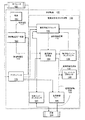
図1は、除細動器105の機能ブロック図である。同図に示すように、除細動器105は、電源155、除細動電圧生成器160、及びアクティベータ170を備えており、その全ては既知の除細動器の構成要素である。本発明によれば、除細動器105は電荷決定式波形生成器100も備えている。
【0031】
電源155は、外部又は内部型除細動器に用いるのに適した様々な既知の電源のうち任意のものとすることが可能である。電源155は、除細動電圧162を生成するために除細動電圧生成器160により既知の技法に従って処理される電源電圧157を供給する。後述のように、除細動電圧162は、電荷決定式波形生成器100の構成要素に供給される。除細動電圧生成器160は、アクティベータ170により起動させられる。除細動電圧生成器160により生成される高エネルギーのため、また、除細動器105の偶発的な放電による患者又はオペレータに対する危険正のために、生成器160は、一般に患者に除細動を施すためにその使用が必要になるまで非活動状態に維持される。次いで、アクティベータ170が、オペレータ150により使用可能にされる。外部型除細動器の場合、オペレータ150は、一般に人間であるが、マシンとすることも可能である。また、内部除細動器の場合には、オペレータ150は一般に装置であり、該装置は、心室細動その他の電気療法の作用を受けやすい考え得る他の異常な心臓活動を検出し、アクティベータ170を使用可能にして、内部除細動器を自動的に起動させるものである。アクティベータ170は、一般に、既知のスイッチ、リレー、論理回路及び素子、及び/又は、他の素子を含む、さまざな既知の装置のうちの任意のものとすることが可能である。例示の実施態様の場合、後述するように、アクティベータ170により電荷決定式波形生成器100の構成要素が起動される。
電荷決定式波形生成器100
電荷決定式波形生成器100は、患者190に適用される適用除細動波形122を生成する。「電荷決定式(charge-determined)」という用語は、所望の量の電荷を患者の心臓に適用するように波形122が決定されることを意味している。図1において、適用除細動波形122は、後述する患者絶縁リレー185、及び患者190の胸部に取り付けられた電極(不図示)を介して患者190に適用される。
【0032】
図1に示す例証となる実施態様の場合、電荷決定式波形生成器100の2つの主な機能が、電荷供給プロセッサ110及び適用波形生成器120により表されている。電荷供給プロセッサ110は、少なくとも部分的に、1つ又は2つ以上の患者インピーダンス値、及び患者への適用が所望される電荷量に基づいて、波形制御信号112を生成する。次いで、制御信号112の制御下で、適用波形生成器120は、患者に所望の量の電荷を適用する適用除細動波形122を生成する。電荷決定式波形生成器100の他の機能要素として、動作時(operational)インピーダンスセンサ130、フィードバックプロセッサ140、及び初期インピーダンスセンサ180があるが、これらは何れも既知の除細動器の構成要素である。係る構成要素については、電荷供給プロセッサ110に関するより詳細に説明した後に、適用波形生成器120の動作に関連して説明することにする。
電荷供給プロセッサ110
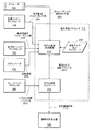
図2は、電荷供給プロセッサ110の機能ブロック図である。既述のように、電荷供給プロセッサ110は、多数の因子に基づいて波形制御信号112を生成する(該因子のうちの幾つかが所望の波形パラメータとすることが可能なものとなる)。ここで開示する例証となる実施態様では、それらの因子には、1つ又は2つ以上の患者インピーダンス、及び患者への適用が所望される電荷量が含まれる。電荷供給プロセッサ110は、これらの因子に基づいて意図する波形パラメータ264を決定するモデル波形決定装置210、及び意図する波形パラメータ264に基づいて適用波形生成器120へ波形制御信号112を送るモデル波形コントローラ215を備えている。
【0033】
決定装置210及びコントローラ215の機能は、様々な既知の又は将来のマイクロプロセッサ又はそれと同様の装置により実施することが可能である。かかる装置は、該装置の記憶装置若しくは該装置に関連する記憶装置に格納されたソフトウェアにより、又は、ファームウェア、ハードウェア、又はその任意の組み合わせの制御下で実行されるプログラムにより、制御されるものとなる。例えば、決定装置210及びコントローラ215の機能は、関連するROMを備えたIntel 80196(商標)マイクロプロセッサにより実施可能である。もちろん、決定装置210及びコントローラ215により実施される機能は、単一の機能要素(例えば、関連するメモリを備えた単一のマイクロプロセッサ)により実施されるものとして説明することが可能である。電荷供給プロセッサ110の機能は、ただ単に例示の便宜上及び分かりやすくするためだけに、2つの機能要素(210,215)により実施されるものとして説明している。
【0034】
上述のように、意図する波形パラメータ264を決定するために決定装置210により用いられる因子は、患者の心臓に適用される所望の電荷量、患者のインピーダンスを表す1つ又は2つ以上の値、及び振幅及び持続時間を含む波形形状を含むことが可能である。これらの因子の幾つか又は全ては、図2に「オペレータにより選択された値252」(以下「オペレータ選択値」と称す)で示すように、オペレータ150により指定されることが可能なものである。また、これらの因子の一部又は全ては、波形データ及びテンプレート212で示すように予め決定しておくことが可能である。この予め決定された情報は、マイクロプロセッサのレジスタ、ROM、マイクロプロセッサによるアクセスが可能な別の記憶装置、専用の電気回路に記憶させ、又は、データを記憶するための他のあらゆる既知の又は将来の技法に従って記憶することが可能である。更に、患者インピーダンス値は、例えば、初期インピーダンスセンサ135又は動作時インピーダンスセンサ130により測定することも可能である。これらの測定値は、それぞれ、初期患者インピーダンス値254及び動作時患者インピーダンス値256により表される。次に、これら考え得る情報源のそれぞれについて詳述することにする。
【0035】
オペレータ選択値252は、様々な既知の技法の任意の1つを用いてオペレータ150により選択することが可能である。例えば、上述のように、オペレータ150は、スイッチ、ダイヤル、又は所定の値を選択するための他の電気機械式装置を操作したり、表示装置(不図示)を用いたグラフィカルユーザインターフェイス等の入力装置を利用して値を供給したり、これらの技法の組み合わせを利用するといったことが可能である。オペレータ選択値252は、既知の技法を利用して、マイクロプロセッサのレジスタ、ROM、又はマイクロプロセッサによるアクセスが可能な別の記憶装置に記憶させることが可能である。これらの記憶された値は、次いで、例示する決定装置210のマイクロプロセッサにより、後述するように、意図する波形パラメータ264を決定するために用いられる。
【0036】
場合によりは、オペレータ選択値252により、意図する波形パラメータ264を完全に決定することが可能である。かかる場合には、モデル波形決定装置210の機能は、単にオペレータ150により選択された値をモデル波形コントローラ215に渡すことのみとなる。例えば、オペレータ150は、振幅が750ボルトで持続時間が10ミリ秒の直線電圧パルスを利用して、50オームの抵抗に相当する想定インピーダンスを有する患者に、0.15クーロンの電荷を適用したいと指定することが可能である(0.15クーロン=750ボルト/50オーム×10ミリ秒)。これらの選択は、患者に所望の量の電荷を適用するための電圧波形を完全に記述するものとなる。従って、モデル波形決定装置210において計算又は他の決定を行う必要がない。他の例では、患者に供給される電荷(時間と共に供給される電流量に基づいてオペレータ150により計算され、又は別様に決定される)が所望の電荷量にほぼ等しくなるように、オペレータ150が、異なる振幅又は持続時間を選択し、又は正弦波形等を選択することが可能である。
【0037】
しかし、より一般的には、オペレータ150は、前述の例の全ての値を指定するわけではない。例えば、オペレータ150は、単に患者に0.15クーロンの電荷を適用したいということしか指定しないことも可能である。オペレータ150は、多数の典型的な除細動の適用例で良好な結果が得られることが認められている場合にその値を選択することができる。この場合、モデル波形決定装置210は、患者に所望の電荷を供給するのに必要とされる、波形パラメータ262の追加値(即ち、患者インピーダンス及び波形形状並びに振幅及び持続時間)を決定する。決定装置210は、上述の他の情報源(即ち、波形データ及びテンプレート212、初期インピーダンスセンサ135、及び/又は動作時インピーダンスセンサ130)の1つ又は2つ以上を利用して、かかる決定を行う。
【0038】
例えば、既知の技法によるソフトウェア、ファームウェア、及び/又はハードウェアの制御下で、決定装置210は、初期インピーダンスセンサ135を起動させる。該初期インピーダンスセンサ135は、初期患者インピーダンス254(例証のため50オームに相当するものと仮定する)を既知の態様で提供する。また、決定装置210は、2相直線波形といった多くの考え得る波形形状の1つを選択する。これらの様々な形状は、データ及びテンプレート212の波形テンプレートに適宜格納することが可能であり、当業者に周知の技法に従って決定装置210により読み出すことが可能である。この選択は、好ましい波形形状の所定の順序に基づいて行うことが可能である。例えば、2相直線波形は、一般に、特定の範囲内、又はオペレータ150により指定されたパルス持続時間及び/又は振幅の範囲内における、所望の変化の値にとって最も有効なものであることが、研究及び/又は経験により明らかとなっている。また、異なる所望の電荷といった他の要素をオペレータ150が指定した場合、又は初期患者インピーダンス値254が特定の波形形状を用いた際に過度の電流を適用させてしまうものである場合等には、別の波形形状がより有効及び/又は安全なものとなることが、研究及び/又は経験により明らかとなっている。
【0039】
波形形状パラメータ(即ち2相直線等)が決定されると、決定装置210は、所望の電荷が患者に供給されるように、振幅及び持続時間パラメータを決定する。例えば、ここでは、例証のため、所定の形状が持続時間10ミリ秒の単相直線パルスであると仮定する。また、例証のため、パルスが電圧パルスであると仮定する(ただしこれに限定されるものではない)。既述のように、初期患者インピーダンス値254は50オームの電気抵抗に相当すると最初の例証で仮定されている。
【0040】
ある実施態様では、決定装置210は、電荷が、瞬時電流(この例の場合、電圧を抵抗で割った値)を時間で積分したものに等しくなるという関係を適用することにより、この例証となる電圧パルスの振幅を決定する。従って、この例では、決定装置210は、0.15クーロンの所望の電荷が、750ボルトの定振幅を有する10ミリ秒にわたる直線電圧パルスにより達成されるものと決定する(0.15クーロン=(750ボルト/50オーム)×10ミリ秒)。この決定は、ソフトウェア、ファームウェア、ハードウェア、又はそれらの任意の組み合わせを用いて実施されるプログラムの制御下で決定装置210により実施される既知の計算技法に従って行われる。同様に、オペレータ選択値252に、電圧振幅が750ボルトでなければならないという要件が含まれている場合には、決定装置210は、所望の0.15クーロンの供給を実現するためにパルス持続時間が10ミリ秒であると算定することになる。別の例において、初期患者インピーダンス値254が100オームの電気抵抗に相当する場合には、明らかに、決定装置210は、電圧パルスの振幅が10ミリ秒の持続時間にわたる1500ボルトであると決定する。他の実施例では、決定装置210は、ルックアップテーブル、探索及び比較技法、又は他の既知の技法を用いて、意図する波形パラメータの上述その他の決定を行う。例えば、波形データ及びテンプレート212におけるデータテーブル(不図示)によって、所望の電荷により索引付けされた様々な波形のパルス振幅及び持続時間に関するオプションを提供することが可能である。このため、0.15クーロンの索引変数を使用して、決定装置210は、1500ボルトの直線電圧パルスに関して患者インピーダンス値が100オームの場合に100ミリ秒の持続時間値をテーブルから抽出することができる。
【0041】
当業者者には今や明らかなように、決定装置210は、供給されるべき所望の電荷のオペレータ選択値及び/又は所定の値、患者インピーダンス、波形の形状、持続時間、振幅、及びその他のパラメータの様々な組み合わせを同様に処理することが可能である。即ち、決定装置210は、電荷が所定時間にわたる電流に等しいという一般的な関係、及び電流が印加電圧を患者インピーダンスで除算した値に等しいといったような他の周知の電気的な関係を利用して、上記の値のうちの1つ又は2つ以上を他の値が与えられた際に決定する。
【0042】
決定装置210はまた、モデル除細動波形の振幅、持続時間、又はその他の形状の態様に関連した様々な因子を表すデータ及びテンプレート212中のデータにアクセスすることが可能である。例えば、大電流、過度の瞬時エネルギー又は総エネルギー、及び/又は他の因子が心臓組織に損傷を与えることによって除細動の成功率が低下することが、研究又は経験により明らかとなっている。別の例として、持続時間が過剰なパルスも、除細動の成功率を低下させるものとなり得る。これらの因子は、所定のデータとしてデータ及びテンプレート212に格納すること、及び/又はデータの表現、格納、及び読み出しに関する既知の技法に従ってオペレータが入力又は調整することが可能である。例えば、持続時間が10ミリ秒の直線パルスを用いて、100オームに相当するインピーダンスを有する患者に、0.2クーロンを供給することが所望される場合には、2000ボルトのパルス振幅(20アンペアの電流)を決定装置210より決定することが可能である。しかし、決定装置210は、探索及び比較技法といった様々な既知の技法の任意の1つを利用し、データ及びテンプレート212を参考にして、20アンペアが直線パルスに用いるには過剰な電流であると判定することが可能である。よって、既知のプログラミング技法によるソフトウェア、ファームウェア、及び/又はハードウェアの制御下で、決定装置210は、パルス持続時間を20マイクロ秒まで延長すると共に電圧振幅を1000ボルトまで低下させることにより、異なる波形パラメータを使用して同じ所望量の電荷を達成することが可能となる。しかし、決定装置210は、データ及びテンプレート212を同様に参考にして20ミリ秒の持続時間が過剰であると判定した場合に、別の波形形状を選択すること、及び/又は、選択された所望の電荷量が安全に達成できないものであることをオペレータ150に示すことが可能である。
【0043】
同様に、決定装置210は、初期インピーダンスセンサ135及び/又は動作時インピーダンスセンサ130により得られる情報に基づいて、意図する波形パラメータ264の様々なパラメータを決定及び/又は調整することが可能である。既述のように、初期インピーダンスセンサ135は、除細動波形を適用する前に、患者のインピーダンスを表す初期患者インピーダンス値254を検知する。例えば、決定装置210は、アクティベータ170による起動時に、センサ135に制御信号を送り、患者に少量の電流を放電して患者の初期インピーダンスを検知するように命じることが可能である。また、動作時インピーダンスセンサ130は、電流、電圧、又はその他の値の瞬時、ピーク、平均、又はその他の測度といった、適用波形生成器120の様々な動作パラメータを測定することにより、動作時患者インピーダンスを測定することが可能である。既知の技法を利用すると、これらの測定により、適用除細動波形122が最初に適用されるとき(即ち波形の適用とほぼ同時)、及び/又は該波形の適用期間の一部又は全てにわたり、患者インピーダンスが表示される。
【0044】
上述のように、患者インピーダンスは、初期の所定の値又はオペレータ選択値と初期インピーダンスセンサ135により検知された値との間、初期インピーダンスセンサ135により検知された値と動作時インピーダンスセンサ130により検知された値との間、及び/又は適用除細動波形122の適用中に動作時インピーダンスセンサ130により検知される個々の値の間で、変化する可能性がある。決定装置210は、患者インピーダンスに関する新しい情報に鑑みて所望の供給電荷量を維持するために、意図する波形パラメータ264に調整を加える。例えば、患者のインピーダンスが、10ミリ秒のパルスの中途で、50オームの抵抗に相当する初期値から100オームに相当する値へと変化したことが検知された場合には、決定装置210は、その患者インピーダンスの変化が検出された際に電圧振幅を750ボルトから1500ボルトへと調整することが可能である。このようして、所望の0.15クーロンの電荷供給が維持される。
【0045】
コントローラ215は、意図する波形パラメータ264に基づいて、適用波形生成器120に波形制御信号112を供給して、該適用波形生成器120が適用除細動波形122を生成できるようにする。上述のように、コントローラ215の機能は、決定装置210に含まれるものとして説明することが可能であるが、分かりやすくするため、この説明においては切り離されている。
【0046】
フィードバックプロセッサ140は、適用除細動波形122が、意図する波形パラメータ112に一致するか否かに関するフィードバックを、既知の技法を用いてコントローラ215に提供する。より詳細には、コントローラ215は、1つ又は2つ以上の意図する波形パラメータ112の標識とフィードバックプロセッサ140により提供されるシステム性能(システム性能パラメータ262として示す)の標識とを比較する。例えば、コントローラ215は、意図する波形パラメータ112の電圧値とフィードバックプロセッサ140により供給される適用除細動波形122の対応する電圧値の標識とを比較する。これらの振幅間には差が存在し得る。即ち、波形基準パラメータと対応するシステム性能パラメータとの間に差が存在する可能性がある。この差を便宜上誤差値と称することにする。実施例によっては、誤差値が存在する場合に、コントローラ215は、適用波形生成器120に対する波形制御信号112を変化させて、実際の値を所望の値に一致させる。例えば、後述する例示の実施態様に関して、コントローラ215は、適用波形生成器120のステップアップ又はステップダウンコンバータに対する波形制御信号112を調整することが可能である。誤差値がしきい値を超えた後に訂正動作を行うことが必要となる場合もある。従って、コントローラ215は、誤差値を監視し、誤差値が許容可能なレベルになるまで訂正動作を行う。
適用波形生成器120
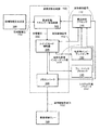
図3は、上述のように意図する波形パラメータ264に基づいて適用除細動波形122を生成する適用波形生成器120を示す機能ブロック図である。該適用波形生成器120は、可変除細動波形を生成する様々な装置の任意の1つとすることが可能なものである。本書で用いる「可変」という言葉は、振幅、持続時間、又は形状の1つ又は2つ以上を変更することにより波形を調整することが可能であることを意味している。上述の所望の電荷量、患者インピーダンス、及びその他のパラメータが予め決定されており、調整可能でない場合には、この調整能力は必要とされない。かかる特殊な場合には、適用波形生成器120は、単に所定の適用除細動波形122を生成できるものであればよく、電荷供給プロセッサ110の機能は、その所定の波形を記述するデータを単に供給することに制限されることになる。しかし、より一般的には、適用除細動波形122が、意図する波形パラメータ264の変化(例えば患者に供給される所望の電荷量のオペレータ150による様々な選択によるもの)を反映することが可能となるよう適用波形生成器120が可変波形を生成することが可能であることは有利である。例えば、振幅が750ボルトで持続時間が10ミリ秒の直線電圧パルスを利用して、50オームの抵抗に相当するインピーダンスを有する患者に0.15クーロンを供給することが所望される場合を再度想定する。この場合、適用波形生成器120は、コントローラ215からの波形制御信号112に応じて前記振幅及び持続時間を有するパルスを生成することが可能であるべきである。また、適用波形生成器120は、オペレータ150が患者に0.2クーロンを供給することが望ましいと決定した場合に1000ボルトで10ミリ秒のパルスを生成することが可能であるべきである。
【0047】
便宜上及び例証のためだけに、以下では、適用波形生成器120は、発明者としてDaniel F.Mulhauserの名前が挙げられている、ヒューレットパッカード社に譲渡され、1998年11月13日に提出された、出願番号が09/191,662の「Method and Apparatus for Providing Variable Defibrillation Waveforms Using Switch-Mode Amplification」と題する米国特許出願(以下、Mulhauser出願と称す)に記載のスイッチモード(switch-mode)増幅器を備えているものと仮定する。しかし、本発明は適用波形生成器120に関するこの例示の実施態様に制限されるものではないことが理解されよう。
【0048】
図3に示すように、適用波形生成器120は、急速放電エネルギー蓄積装置320、スイッチモード増幅器325、及び2相コンバータ330を備えている。急速放電エネルギー蓄積装置320は、除細動電圧生成器160から供給されるエネルギーを蓄積して充電電圧322を形成する。一般に、外部型除細動器に関する例示の実施態様の場合、急速放電エネルギー蓄積装置320は、除細動器に用いられる様々な既知のエネルギー記憶装置の任意の1つ(例えば約30〜200マイクロファラッドの範囲内のキャパシタンスを有すると共に数千ボルトのオーダの充電電圧を保持することが可能な薄膜コンデンサ)とすることが可能である。既知の除細動器の急速放電エネルギー蓄積装置に関する他の例証となる多くの例のうちの1つでは、急速放電エネルギー蓄積装置320は、直列に構成された幾つかの閃光電球用アルミニウム電解コンデンサを備えることが可能である。急速放電エネルギー蓄積装置320は、除細動に適した電荷を蓄積すると共に急速に放電することが可能なものであれば、多くの既知の装置又は今後開発されることになる装置のうちのどれが利用されるかは本発明にとって重要ではない。
【0049】
図4は、スイッチモード増幅器325の一実施態様を示す機能ブロック図である。スイッチモード増幅器325は、単なる例証のためのものであって、多くの代替的な実施態様が可能であり、どの実施態様を用いるかは本発明にとって重要ではない。スイッチモード増幅器325は、ステップアップコンバータ420、ステップダウンコンバータ410、及び出力エネルギー蓄積装置430を備えている。スイッチモード増幅器325の代替実施例は、ステップダウンコンバータ420及び/又は出力エネルギー蓄積装置430を含む必要のないものとなる。ステップアップコンバータ420(又は代替実施態様における別のタイプの増幅器)の機能は、充電電圧322を選択的に増幅させることである。実施態様によっては、ステップアップコンバータ420及びステップダウンコンバータ410の一方又は両方が、装置430等の出力エネルギー蓄積装置を含むことが可能である。このため、ステップアップコンバータ420又はステップダウンコンバータ410に対する今後の言及に関し、それらが1つ又は2つ以上の出力エネルギー蓄積装置を含むことも可能であり、また該装置を共用装置とすることも可能である。明瞭化及び例証を目的として、以下では、出力エネルギー蓄積装置430について別個に言及することもある。
【0050】
ステップダウンコンバータ410は、充電電圧322を選択的に低下させてステップダウン電圧412を生成する。この選択的な低下は、制御信号ライン402を介して伝送されるコントローラ215からの制御信号に応じて実施される。ステップアップコンバータ420は、ステップダウン電圧412を受容し、該電圧を選択的に増幅して増幅電圧422を生成する。この選択的な増幅は、制御信号ライン404を介したコントローラ215からの制御信号に応じて実施される。出力エネルギー蓄積装置430は、増幅電圧422を受容し、該電圧をフィルタリングして出力電圧432を提供し、該電圧が2相コンバータ330に提供される。制御信号ライン402,404は、図1及び図2における波形制御信号112を提供するものとなる。
【0051】
次に、図5の簡素化された回路図及び図6に示す波形に関してスイッチモード増幅器325の動作について更に詳述する。図5は、2相コンバータ330及び患者絶縁リレーmidori185を含む図4のスイッチモード増幅器の一実施例に関する回路図である。図5の例証となる回路は主たるトポロジのみを表すよう簡素化されていることが理解されよう。このため、構成要素又は接続で省略されているものがあるが、かかる省略部分は当業者には明白であろう。例えば、トランジスタスイッチに対する制御信号は示しておらず、明瞭化のため、単純なスイッチ記号を使用してトランジスタスイッチ素子を表している。
【0052】
図4の機能要素と図5の回路要素との対応は次の通りである。急速放電エネルギー蓄積装置320は、図5の回路ではコンデンサ510により実施されている。出力エネルギー記憶装置430は出力コンデンサ560により実施されている。ステップダウンコンバータ410は、バック(buck)トランジスタ(以下、バックスイッチと称す)515、バック(buck)ダイオード520、インダクタ530、及びコンデンサ560により実施されている。ステップアップコンバータ420は、ブーストトランジスタ(以下、ブーストスイッチと称す)540、ブーストダイオード550、インダクタ530、及び、コンデンサ560により実施されている。従って、この実施例では、インダクタ530及びコンデンサ560は、ステップダウンコンバータ410及びステップアップコンバータ420により共用され、これによりスイッチモード増幅器325の実施に要する構成要素の数が有利に減少する。2相コンバータ330は、スイッチ570,572,574,576から構成されるHブリッジにより実施される。負荷抵抗580は、患者インピーダンスを表している。この表現は、例証のために単純化したものであり、患者インピーダンスは、容量及び/又は誘導成分を含むことが可能であり、また、より一般的には複雑な抵抗属性及びリアクタンス属性を含む可能性がある、ということが理解されよう。患者絶縁リレー185は、スイッチ582,584(様々な電気又は機械式スイッチの任意のものとすることが可能)により実施される。
【0053】
図5に示すように、除細動電圧生成器160は、コンデンサ510の一方の側の電源ノード505に除細動電圧162を供給される。該コンデンサ510の他方の側は、共通電圧500に接続されている。便宜上、共通電圧500は、接地されているものと仮定するが、そうする必要はない。バックスイッチ515は、電源ノード505に接続された第1のノード516と、コントローラ215からの制御信号ライン402に接続された制御ノード518とを有している。該バックスイッチ515はまた、インダクタ530の入力ノード531に接続されると共にバックダイオード520の出力ノード521に接続された第2のノードも有している。バックダイオード520は、共通電圧500に接続された入力ノード522を有している。インダクタ530は、ブーストスイッチ540の第1のノード543及びブーストダイオード550の入力ノード551に接続された出力ノード532を有している。ブーストスイッチ540は、共通電圧500に接続された第2のノード542、及び制御信号ライン404を介してコントローラ215に接続された制御ノード541も備えている。ブーストダイオード550は、コンデンサ560の第1のノード561、及びスイッチ570,572から構成されるHブリッジの2つの脚に接続された出力ノード552を備えている。コンデンサ560は、共通電圧500に接続された共通ノード562を備えている。Hブリッジの他の2つの脚は、スイッチ574,576から構成される。明らかに、Hブリッジの反対側の脚におけるスイッチ570,576が閉じ、スイッチ572,574が開いている場合に、患者絶縁リレースイッチ582,584が閉じているものと仮定すると、電流は、スイッチ570、負荷抵抗580、及びスイッチ576を通って、共通ノード(即ち共通電圧500に接続されたノード)に流れる。同じ仮定の下で、Hブリッジの反対側の脚におけるスイッチ572,574が閉じ、スイッチ570,576が開いている場合、電流は、スイッチ572、負荷抵抗580、及びスイッチ574を通って共通ノードへと流れる。
【0054】
上述のように、バックスイッチ515又はブーストスイッチ540は、絶縁ゲートバイポーラトランジスタ、電界効果トランジスタ、若しくはその他の既知の固体装置、又は現在開発中か今後開発されることになる同様のデバイスにより実施することが可能である。バックダイオード520又はブーストダイオード550は、適正に同期がとられたトランジスタスイッチにより実施可能である。Hブリッジスイッチ570,572,574,576も、同様に、絶縁ゲートバイポーラトランジスタ、電界効果トランジスタ、シリコン制御整流素子、又はその他の既知の固体装置、あるいは今後開発されることになる同様のデバイスにより実施可能である。これらのスイッチ又はダイオードの何れも、単一の構成要素に限定する必要はなく、例えば、電圧及び電流を共用するため適正に抑制及び制御された、絶縁ゲートバイポーラトランジスタ又はダイオードの直列又は並列の組み合わせを含むことが可能である。かかる組み合わせの設計及び利用については当業者に周知のところである。
【0055】
図6は、共通の時間軸に沿って位置合わせされた、図5の回路の選択された回路素子に対する制御信号、及びその結果として生じる電流及び電圧波形の例証となる実施態様をグラフで表したものである。この共通の時間軸は、時間線600により表されている。例証のため、時間ライン600で示す初期時間601に先立って、オペレータ150が、アクティベータ170を起動させて、除細動電圧生成器160が、充電電圧322を生成するよう急速放電エネルギー蓄積装置320を充電させているものと仮定する。また、例証のため、初期時間601に先立ち、やはり、オペレータ150によるアクティベータ170の起動に応じて、該アクティベータ170が初期インピーダンスセンサ180をイネーブルにしているものと仮定する。
【0056】
制御信号605は、Hブリッジスイッチ570,576の状態を制御する。例証となるこの例では、制御信号605は、初期時間601から後続時間603にわたりスイッチ570,576に印加される制御電圧が低レベル状態にあることを示す電圧波形であるが、これは、それらのスイッチが開かれていることを示すために例示的に想定したものである。例えば、電圧レベル606はゼロボルトとすることが可能である。時間603において、制御信号605の電圧レベルは、正電圧607、例えば5ボルトまで上昇する。この高レベル電圧状態は、スイッチ570,576が閉じられることを示すために想定されたものである。本例において、これらの電圧レベルは任意に選択することが可能であり、2レベルの電圧以外からなる信号を利用することが可能であり、より一般的には、多種多様な制御信号を利用してスイッチを開閉させることが可能である、ということが理解されよう。人間の心臓のクロナキシー(chronaxie)時間に一致する例証となる一実施形態では、時間603は約6ミリ秒とすることが可能である。当業者には明らかなように、スイッチ570,576がオンになるのとほぼ同時にHブリッジスイッチ572,574をオフにすることにより、2相変換が達成される。このため、該例証となるこの実施形態では、制御信号610は、初期高レベル電圧611(例えば5ボルト)で示すようにスイッチ572,574が当初は閉じていることを示している。時間603で、これらのスイッチが低レベル電圧612で示すように開かれる。
【0057】
制御信号605,610は、例証となる実施態様ではコントローラ215により生成され、このため波形制御信号112の様々な側面を呈するものとなる。様々な既知のタイミング回路、装置、又は技法の任意のものを利用して、かかる信号を生成することが可能である。また、代替的な実施態様では、Hブリッジ又は2相コンバータに対する2相制御信号をコントローラ215により生成する必要がない。この場合、該2相制御信号は、除細動器105の2相コンバータ330その他の構成要素に含まれるタイミング回路又は装置により提供することが可能である。更に、制御信号605,610は、タイミング要素に基づく必要もなく、増幅器325の任意の構成要素における電圧が所定のレベルに達し又は該レベルと交差するといった他の事象によりトリガすることも可能である。
【0058】
時間601と時間603との間の期間中に電流がスイッチ572,574を流れると、図5に示すように、負荷抵抗580の両端間に「正」電圧と任意に呼ばれるものが生成される。このため、適用除細動波形122(この例ではパドルを介して患者に適用される電圧波形)は、その時間期間中に正相(positive phase)を有するものとなる。明らかに、適用除細動波形122は、時間603の後に負相を有するものとなる。これは、電流が負荷抵抗580を逆方向に流れるからである。
【0059】
例証となる実施態様のバック(buck)制御信号620は、制御ライン402を介してコントローラ215によりバックスイッチ515の制御ノード518に印加される電圧である。図示の実施態様では、バックスイッチ515は(ブーストスイッチ540と同様に)スイッチの働きをする。例証のため、制御信号620が図6の電圧621(例えば5ボルト)のように高レベル状態にある場合にバックスイッチ515が閉じているものと仮定する。バック制御信号620が電圧622のように低レベル状態になると、バックスイッチ515が開く。バック制御信号620(及び後述のブースト制御信号640)により表される結果的に生じるパルス幅変調を図6に固定周波数として示す。しかし、当業者には明らかなように、一定のオン/オフ時間、及び可変周波数変調、又は、ヒステリシス制御といった、代替技法を利用することも可能である。
【0060】
図6の時間ライン600で示す初期時間610から後続時間602までの時間期間は、バックスイッチ515が、バック制御信号620のパルスに従って間欠的に開閉される期間である。しかし、時間601から時間602までのブースト制御信号640の部分により示すように、ブーストスイッチ540は常に開いている。このため、この時間期間は「バック相(buck phase)」と呼ぶことが可能である。この例証となる例におけるバック相の持続時間を任意に約4.8ミリ秒と仮定する。当業者には明らかなように、バック制御信号620の各オンパルス中に、電流がインダクタ530を通って出力コンデンサ560に流れる。その電流が図6にインダクタ電流波形660として表されている。この例証となる例の場合、インダクタ電流波形660は、電流レベル663により表される低レベルから電流レベル664により表される高レベルへと変化する。中間電流レベル662も示されている。例証となる実施態様におけるこれらの電流レベルに関する一般的な値は、電流レベル663が18アンペア、電流レベル662が20アンペア、電流レベル664が22アンペアである。明瞭化のため、これらの電流レベルは、時間軸の全長にわたって描かれておらず、単に時間軸の開始部に示されているだけである。明らかに、インダクタ530を通る電流は、バックスイッチ515が閉じている間に増大し、バックスイッチ515が開いてダイオード520が導通している間に減少し、これにより三角波形が生成される。
【0061】
コントローラ215は、制御信号620のパルス幅(又はパルス幅変調又は周波数変調又はヒステリシス制御の代替実施例における他のパラメータ)を調整して、インダクタ530、スイッチ572、負荷抵抗580、及びスイッチ574を通って共通ノードへ流れる電流を制御する。明らかに、出力コンデンサ560は、高周波パルス出力のフィルタリングを提供するものとなる。例えば、制御信号620について上述の時間期間に関して、患者抵抗が通常の典型的な約50オームである場合、出力コンデンサ560は、例えば、約0.5〜5マイクロファラッドのキャパシタンスを有する薄膜コンデンサとすることが可能である。
【0062】
特定の動作モードでは、出力コンデンサ560はまた、除細動器の作動直前に、患者回路(スイッチ582,584及び負荷抵抗580を通る回路)に適用される漏れ電流を有利に最小限に抑えるものとなる。この動作モードでは、出力コンデンサ560は、急速放電エネルギー蓄積装置320が充電するのと同時には充電しない。即ち、出力コンデンサ560は、除細動器が作動する際に充電する。このため、バックトランジスタ515からの漏れ電流は典型的には、出力コンデンサ560に危険な電荷(即ち、患者絶縁リレーにアークを生じさせるのに十分な大きさの電荷、又はリレーが誤って閉じた際に患者又はオペレータに危険を及ぼすことになる電荷)を蓄積するための十分な時間を有さないことになる。
【0063】
上述のように、コントローラ215は、増幅器325の様々な位置における電流の流量(又は電圧レベル)を測定することにより測定することが可能な患者インピーダンスの標識に部分的に基づいてバックスイッチ515を選択的にオン/オフする。例えば、電流センサは、ブーストスイッチ540を通る電流を測定するために、図5に示すように回路分枝506に配置することが可能である。同様に、電流センサは、任意のスイッチ又はダイオード分枝において、又はその他の任意の回路分枝において、ポイント501(インダクタ530を流れる電流を測定するため)、ポイント503(出力電流を測定するため)といった位置に配置することが可能である。当業者には、電流及び/又は電圧センサの配置に適した位置が明らかであろう。図1ないし図4のフィードバックプロセッサ140は、この患者インピーダンスの標識を検知してその測度をコントローラ215に提供する機能を表している。図4の接続ライン424は、センサがステップアップコンバータ420に(回路分枝506等において)配置される実施例を表している。接続ライン414は、センサが、ステップダウンコンバータ410内に配置される代替実施例を表している。接続ライン416は、センサが出力エネルギー蓄積装置430と2相コンバータ330との間に(ポイント503等において)配置されるもう1つの実施例を表している。ライン424,414,416は、代替実施例において、それらの任意の1つ又は任意の組み合わせを用いることが可能であることを表すために、点線で示されている。
【0064】
図6から明らかなように、連続した鋸歯状のインダクタ電流波形660の振幅は、バック相において減衰する。これは、急速放電エネルギー蓄積装置320が放電するからである。このため、充電電圧322が低下して出力電圧に近づく。この期間中に、負荷抵抗580の両端間の電圧は、制御信号620の周波数の選択に起因して、出力コンデンサ560(例えば1〜5マイクロファラッド)、インダクタ530、及び負荷抵抗580(例えば50オームとすることが可能な患者に依存する値)により表されるLRC回路の時定数と比較してほぼ一定となる。当業者には既知のように、ノード507における平均電圧は、バックスイッチ515のデューティサイクルに充電電圧322(時間と共に減衰するもの)の時間平均値を乗算した値に等しい。該デューティサイクルは、「バックスイッチ515が閉じている時間」対「定周波数パルス幅変調信号620の周期」の比である。
【0065】
従って、バック相においてデューティサイクルを変化させることにより(即ち充電電圧322の低下時に増大させることにより)、ノード502の電圧を電圧681のようなほぼ一定のレベルに維持することが可能になる。典型的な除細動器の用途では、電圧681は、例えば約1,000ボルトとすることが可能である。出力電圧波形680において、電圧681は、基準電圧683(この例証となる例の場合には0ボルトと仮定されている)に関連して示されている。ステップダウン変換のため、電圧681は、充電電圧322の初期値未満とすることが可能である。また、ステップアップ変換に先立つステップダウン変換により、何れかの変換ステージが動作しなければならないデューティサイクルの範囲が縮小される。
【0066】
充電電圧322が減衰するにつれて、鋸歯状のインダクタ電流波形660の振幅は、適用除細動波形122の入力電圧322と出力電圧とが等しくなるまで、連続的に減衰していく。次いで、コントローラ215は、ブーストスイッチ540が非ゼロのデューティサイクルを有することを意味する「ブースト相」を開始する。同時に、バックスイッチ515は、完全にオンの状態を維持する。図6の例証となる実施態様の場合、バック相からブースト相へのこの遷移は、時間ライン600で示すように、時間602において生じる。ブースト相では、コントローラ215は、ブーストスイッチ540のデューティサイクルをゼロから次第に大きい値へと増大させる。即ち、図6のブースト制御信号640に関し、ブーストスイッチ540は、例証となる例の場合、正のパルス641から始まって間欠的にオンになる。バック制御信号620に関して明らかなように、バックスイッチ515はブースト相でオンになる。このため、一度に1つのコンバータしか動作しないが、代替実施例の場合にはそうする必要はない。
【0067】
ブースト相において、ブースト回路の動作により、ノード502の電圧がノード508に生じる電圧よりも(ステップアップコンバータ420への入力に対応して)高くなる。この増幅が生じるのは、ブーストスイッチ540が閉じた際にインダクタ530にエネルギーが蓄積され、即ち、インダクタ530に電流が流れるようブーストスイッチ540がアースへの電流経路を形成するからである。ブーストスイッチ540が開くと、誘導電流が、強制的にブーストダイオード550を介して出力コンデンサ560に送り込まれ、そこからHブリッジ及び負荷抵抗580へと流れることになる。ブーストスイッチ540が開いているこの時間中に、インダクタ530の両端間における誘導電圧は、ノード531に関して測定されたように、ノード532ではより高い正の値になる。このため、インダクタ530は、電流の流量を維持する際に、ノード502における電圧を、ノード508における電圧レベルを超えて上昇させることになる。ブースト相において、負荷抵抗508の両端間における電圧は、充電電圧322に比1/(1−デューティサイクル)を乗算した値に比例する。このため、コントローラ215は、制御信号ライン402,404を介してバックスイッチ515及びブーストスイッチ540にそれぞれ適用されるデューティサイクルを変更することにより、負荷抵抗580の両端間における電圧を選択的に維持又は上昇させることが可能である。Hブリッジをバックステージ及びブーストステージの組み合わせに縦続接続することにより、負荷抵抗580の両端間における位相を変化させることが可能である。かかる位相のスイッチが、図6の時間603に示されており、その結果として、負荷抵抗580の両端間における電圧が、符号681で示す正のレベルから、それと等しい絶対値を有する符号682で示す負のレベルへとスイッチされる。
【0068】
波形690は、負荷抵抗580を通る電流を例示している。負荷抵抗580は、例証のため、純粋な抵抗と仮定されるので、明らかに、電流波形690の形状は、電圧波形680の形状と同じになる。実際には、この例証となる仮定が厳密に正確でない可能性があるため、波形680,690は僅かに異なる可能性がある。負荷抵抗580の抵抗が50オームで、その両端間における電圧が上述の通りであると仮定すると、電流波形690は、時間603まで、基準レベル693(0アンペア)に対して正のレベル691(20アンペア)に維持される。時間603で、移相が生じ、負荷抵抗580を通る電流が、負のレベル692(−20アンペア)で示されている。
【0069】
図7及び図8は、本発明の態様に従って所望の量の電荷を患者に供給するための方法の例証となる例を示す単純化されたフローチャートである。次に、図1及び図2の除細動器105の機能要素に関連して、これらの方法の説明を行うことにする。
【0070】
図7を参照する。ステップ710で、患者の心臓に供給される所望の電荷が決定される。モデル波形決定装置210の動作に関連して上述したように、所望の電荷を予め決定することが可能である。即ち、波形データ及びテンプレート212に記憶されたデフォルト値を利用することが可能であり、またオペレータが選択することも可能である。ステップ715に示すように、1つ又は2つ以上の意図する波形パラメータを予め決定し、又はオペレータにより選択することが可能である。これらのパラメータは(もしあれば)識別される。例えば、決定装置210に関連して上述したように、オペレータ150は、直線、単相、電圧パルスとなるように波形形状を選択している可能性がある。別の例として、波形の持続時間が20ミリ秒よりも長くならないように予め選択されている可能性がある。
【0071】
ステップ720では、患者のインピーダンスが決定される。該1つ又は2つ以上の値は、測定し、予め決定し、及び/又はオペレータにより選択することが可能なものである。例えば、センサ130,135に関連して上述したように、それらの値を測定することが可能である。波形データ及びテンプレート212に記憶されているデータに関する場合のように前記値を予め決定することも可能であり、又はオペレータにより選択された値を波形データ及びテンプレート212に格納し、又はユーザにより選択されたデータを獲得し操作するための既知の技法に従って別様に処理することも可能である。
【0072】
ステップ725に示すように、ステップ710で決定された所望の電荷、ステップ720で決定された患者インピーダンス、及びステップ715に関して上述した予め決定され及び/又はオペレータにより選択されたあらゆる波形パラメータに基づいて、1組の意図する波形パラメータが決定される。図2に示す例証となる実施態様を参照すると、このステップはモデル波形決定装置210により行われ、その結果として意図する波形パラメータ264が生成される。適用除細動波形(例えば符号122)は、意図する波形パラメータに基づいて適用波形生成器120により生成することが可能である(ステップ730)。この適用除細動波形が患者に適用することが可能なものである(ステップ735)。
【0073】
更に、ステップ740に示すように、センサ(例えば符号130,135)を使用して、患者インピーダンスを表す値を検知することが可能であり、又はセンサ又はプロセッサ(例えば符号140)を使用して、適用除細動波形の適用中に、患者に流入する電流を測定することも可能である。判定ブロック745で、電流及び/又はインピーダンスが期待通りである(例えば適用除細動波形が意図する波形パラメータにより指定され、供給される電荷量が期待通りである)場合には、ステップ755で、患者に供給された電荷を決定することが可能である。期待通りでない場合には、ステップ750で、その新たな測定値に基づいて、所望の電荷を供給するために、意図する波形パラメータ及び/又は適用除細動波形を調整することが可能である。電荷決定式波形生成器100は、所望の電荷が患者に供給されたか否かを判定することが可能である(判定ブロック760)。所望の電荷が患者に供給された場合には、電荷決定式波形生成器100は、患者に対する電流の流入を停止する(ステップ765)。また所望の電荷が患者に供給されていない場合には、電荷決定式波形生成器100は、電流が患者に流入し続ける際に、患者インピーダンス及び/又は電流の監視を続行する(判定ブロック760及びステップ740)。
【0074】
図8は、本発明の別の態様に関する方法を示す単純化されたフローチャートである。ステップ810で患者のインピーダンスが決定される(例えばユーザにより選択し、予め決定し、又は測定することが可能である)。この例の場合、該ステップは、患者に除細動波形を適用する前に実施されるが、他の実施例ではそうする必要はない。この例示の方法では、電荷決定式波形生成器100は、コンデンサが適当な電気的結合を介して患者に放電した際に所望の(例えば、ユーザにより選択された又は所定の)電荷が患者に供給されるように、コンデンサ(別の実施例では別の種類のエネルギー蓄積装置又は電圧/電流源とすることが可能である)の充電電圧を決定する(ステップ815)。コンデンサは、該充電電圧まで充電される(ステップ820)。次いで、該充電電圧が、コンデンサから患者へと放電される(ステップ825)。本例示の実施例のように、実施例によっては、患者に流入する電流を測定することも可能である(ステップ830)。時間と共に患者に流入する電流を計算し又は別様に決定することにより(ステップ835)、患者に供給される電荷が決定される。(判定ブロック840で)所望の電荷が供給された場合には、患者への電流の流入が停止される(ステップ845)。(判定ブロック840で)所望の電荷が供給されていなければ、患者に流入する電流が引き続き測定され供給される(ステップ830)。
【0075】
これで、本発明の様々な態様の説明を終えるが、当業者には明らかなように、以上の説明は、ただ単に例証のためのものであって、制限を加えるものではなく、単なる例として示されただけである。例えば、本発明によれば、例示の実施態様の様々な機能要素間において機能を分散するための他の多くの方法が可能になる。代替実施態様において、任意の構成要素の機能を様々なやり方で実施することが可能である。従って、本発明に基づいて、制御信号を生成し、事象又はタイミング情報を検出して、制御信号を起動又は終了し、フィードバックを施し、又はこれに応答する等の、数多くの変形例が企図される。本発明に関連して本明細書に解説の機能を実施することが可能な、回路トポロジ及び回路素子の実行可能である変形例が多数存在する。
【0076】
決定装置210及びコントローラ215の機能は、多種多様な既知の技法に従って実施可能である。例えば、個別又は集積電子構成要素により、又はマイクロプロセッサにより実施することが可能である。更に、決定装置210及びコントローラ215に関連して上述の機能を組み合わせることも可能であるし、又は本発明の他の各種機能素子間において、これらの機能の一部又は全てを分散することも可能である。例えば、2相コンバータ330に対する制御は、コントローラ215から制御信号ラインを介してではなく、コンバータ330と一体化された回路により実施することが可能である。蓄積されたエネルギーの消散は、独立したダンプ抵抗で生じさせることが可能であり、又は適正に制御される場合にはインダクタで生じさせることが可能性である。図7及び図8に示す方法ステップも、単なる例証のためのものである。かかるステップ及び/又は決定要素は、代替実施態様では、組み合わせることも、分割することも、他の順序又はシーケンスで実施することも、並行して実施することも、又は別様に再構成することも可能である。また、代替実施態様では、追加のステップ及び/決定要素を加えることも可能である。特許請求の範囲により規定される本発明及びその等価物の範囲内に含まれる数多くの他の実施態様及びその修正実施態様が企図されている。
【0077】
以下においては、本発明の種々の構成要件の組み合わせからなる例示的な実施態様を示す。
1.患者に所望の量の電荷を供給するための方法であって、
(1)電気的結合を介して時間の経過と共に患者に電流を供給し(730,735,825)、
(2)前記時間の経過と共に供給される電流が所望の電荷量に等しくなった際に患者への電流供給を停止する(760,765,840,845)、
という各ステップを含む、患者に所望の量の電荷を供給するための方法。
2.前記ステップ(1)が、1つ又は2つ以上の患者インピーダンス値を決定するステップ(720)を含む、前項1に記載の方法。
3.前記ステップ(1)が、電流の波形の1つ又は2つ以上のパラメータを決定するステップ(725)を含む、前項1に記載の方法。
4.前記波形の前記1つ又は2つ以上のパラメータが、形状、位相、相転移のタイミング、最長持続時間、最短持続時間、最高電圧、最低電圧、最大電流、最小電流、最大エネルギー、最小エネルギー、最大電力、及び最小電力からなるグループから選択される(715)、前項3に記載の方法。
5.所望の量の電荷を患者に供給するための除細動器であって、
前記所望の電荷量に少なくとも部分的に基づいて1つ又は2つ以上の意図する波形パラメータ(264)を決定するよう構成され配置された電荷供給プロセッサ(110)を備えている、除細動器。
6.前記1つ又は2つ以上の意図する波形パラメータのうちの1つ又は2つ以上に基づいて適用除細動波形(122)を生成するよう構成され配置された適用波形生成器(120)を更に備えている、前項5に記載の除細動器。
7.前記1つ又は2つ以上の意図する波形パラメータ(264)が、形状、位相、相転移のタイミング、最長持続時間、最短持続時間、最高電圧、最低電圧、最大電流、最小電流、最大エネルギー、最小エネルギー、最大電力、及び最小電力からなるグループから選択される、前項5に記載の除細動器。
8.前記電荷供給プロセッサ(110)が、1つ又は2つ以上の患者インピーダンスに少なくとも部分的に基づいて1つ又は2つ以上の意図する波形パラメータ(264)を決定するよう構成され配置されている、前項5に記載の除細動器。
9.前記患者インピーダンスの少なくとも1つを決定するよう構成され配置された少なくとも1つのセンサ(130,180)を更に備えている、前項8に記載の除細動器。
10.前記電荷供給プロセッサが前記1つ又は2つ以上の意図する波形パラメータを決定する前に、前記少なくとも1つのセンサのうちの第1のセンサ(180)が前記患者のインピーダンスを表す値を検知する、前項9に記載の除細動器。
【図面の簡単な説明】
【図1】本発明による電荷決定式波形生成器を含む除細動器の一実施態様を示す機能ブロック図である。
【図2】図1の電荷決定式波形生成器の電荷供給プロセッサの一実施態様を示す機能ブロック図である。
【図3】図1の電荷決定式波形生成器の適用波形生成器の一実施態様を示す機能ブロック図である。
【図4】図3の適用波形生成器のスイッチモード増幅器の一実施態様を示す機能ブロック図である。
【図5】図3の適用波形生成器の2相コンバータ及び図1の電荷決定式波形生成器の患者絶縁リレーを含む、図4のスイッチモード増幅器の一実施態様を簡素化して示す回路図である。
【図6】図5の回路の選択された回路要素への制御信号、及び、該回路要素から結果的に生じる電流及び電圧波形の例証となる実施態様を、共通の時間軸に沿って位置合わせして示すグラフである。
【図7】本発明に従って患者に所望量の電荷を供給するための方法の一実施態様を簡素化して示すフローチャートである。
【図8】本発明に従って患者に所望量の電荷を供給するための方法のもう1つの実施態様を簡素化して示すフローチャートである。
【符号の説明】
110 電荷供給プロセッサ
120 適用波形プロセッサ
122 除細動波形
130 センサ
180 センサ
264 波形パラメータ[0001]
BACKGROUND OF THE INVENTION
The present invention relates generally to defibrillators, and more particularly to a defibrillator that provides a variable waveform.
[0002]
[Prior art]
An external defibrillator is a device used to apply a strong electrical shock to two or more electrodes, commonly referred to as “paddles” or “pads”, on the chest of a patient who is in cardiac arrest.
[0003]
If the initial attempt at defibrillation is unsuccessful, one or more additional attempts are generally made. However, repetitive trials of defibrillation (especially when performed with increasing intensity levels) are more likely to damage the heart and other body tissues. Although the threshold level of damage is not well quantified, there appears to be no significant difference between effective defibrillation levels and damaging defibrillation levels. Also, the patient's condition may be exacerbated by delays associated with repeated defibrillation procedures. For example, metabolic imbalance and hypoxia can occur in response to previously attempted resuscitation. In addition, when these conditions occur, it is generally difficult to defibrillate the patient, and even if defibrillation is achieved, the likelihood of successful recovery is reduced. Therefore, selecting various waveform parameters optimally at an early stage is important to increase the possibility of successful results.
[0004]
A set of waveform parameters that are considered important in determining the safety and success of a defibrillation procedure determines the shape of the defibrillation waveform. In general, various shapes of waveforms have been used. Some defibrillators use single-phase (single polarity) voltage pulses. Some use bi-phase (both positive and negative) pulses. Single-phase or two-phase pulses are a damped sinusoidal waveform, truncated exponential waveform, constant “slope” waveform (a measure of the difference between the start and end voltages, the difference between the initial and final voltages divided by the initial voltage In many cases, it is expressed as a combination of these shapes. Many other waveforms are possible, such as linear pulses. Furthermore, the shape of the waveform can be adjusted by changing its amplitude or duration, or one or more amplitudes or durations of its components. US Pat.No. 5,431,686 to Kroll et al. Describes a conventional approach to determining what is considered the optimal shape for a defibrillation waveform supplied by both an implantable defibrillator and an external defibrillator. U.S. Pat. No. 4,953,551 to Mehra et al. And U.S. Pat. No. 4,800,883 to Winstrom.
[0005]
The selection of the waveform shape also depends on whether the defibrillator is implanted or external. When a defibrillator is implanted, the patient's unique electrical characteristics and overall physiology can be examined to tailor the waveform to the needs of that particular patient. In contrast, external defibrillators are generally intended to be applied to many patients with different physiological characteristics. In addition, the patient may require different waveforms, for example depending on the contact made between the electrode and the patient, for optimal effect. Thus, external defibrillators can be designed to provide optimal effects for the average patient. Alternatively, it provides an assessment of patient physiology, electrical connections made between the electrode and patient, new knowledge about the behavior and effects of electrotherapeutic discharge, or various waveforms depending on other factors It is also possible to design so that it can.
[0006]
Several factors have been used to determine defibrillation waveform parameters. That is, many defibrillators currently in use are designed to deliver one or more specific amounts of energy, typically measured in joules, to the patient's heart. In the case of external defibrillators, implementation considerations contributed to the importance of energy-based defibrillation methods. In particular, energy is an amount that is relatively easy to control at power levels, and pulse width is required for transthoracic defibrillation.
[0007]
The American Heart Association guidelines applicable to external defibrillators include a first discharge to supply 200 joules of total energy to the patient, a second discharge to supply 200 to 300 joules, It has been suggested that a third discharge should be applied to provide 360 joules. In accordance with these guidelines, many conventional external defibrillators are designed to deliver those amounts of energy to a patient assuming a typical transthoracic impedance (eg, 50 ohms). Other defibrillators account for transthoracic impedance variability from patient to patient. In general, these defibrillators measure the patient's transthoracic impedance and adjust the amount of energy stored in a discharge capacitor or other energy storage element, thereby the desired amount of energy applied to the patient's heart. To achieve. Some of these conventional defibrillators change the shape of the defibrillation waveform as a function of transthoracic impedance and the amount of energy supplied. The principles of the above and other conventional energy based approaches are described in US Pat. No. 4,771,781 to Lerman, US Pat. No. 5,620,470 to Gliner et al., US Pat. No. 5,607,454 to Cameron et al., And International Patent Application PCT / US98 / 07669 ( It is described in many information sources such as PCT International Publication Number WO98 / 47563).
[0008]
The Lerman patent describes another type of conventional design where the defibrillation discharge is determined based on the current delivered to the patient. That is, Lerman describes a method for calculating the energy level required to deliver a peak current amount preselected by the operator to the patient. Along with the selected peak defibrillation current, the measured transthoracic resistance of the patient is used to control the charge applied to the defibrillator discharge capacitor. Upon discharge, a selected level of peak current is applied to the patient. U.S. Pat. No. 4,840,177 to Charbonnier et al. Also describes a method for determining the charge level of an energy storage element such that a desired current flows into the patient when the energy storage element is discharged. The other conventional current-based designs described above attempt to limit or avoid, among other things, damage that can be caused by excessive amounts of energy supply. For example, in situations where transthoracic resistance is low, a particular selection of the amount of discharge energy for the patient will result in more current being applied than if transthoracic resistance was high. Thus, based on the theory that it is the supply of current rather than the energy itself that achieves the desired defibrillation so that the energy discharged to the low resistance patient is less than that for the high resistance patient. It is possible to select. Thus, the envisaged therapeutic benefit is achieved when the patient is exposed to an energy level that is considered less likely to cause damage. Various other conventional techniques for determining defibrillation discharge parameters based on operational parameters such as desired energy, current, and / or shape are mentioned and discussed in the above-mentioned PCT Publication No. 98/47563. Has been.
[0009]
[Problems to be solved by the invention]
Current-based defibrillators are feasible, but generally must operate over a wide range of energy and power to deliver a specified current over a wide range of possible transthoracic impedances. These requirements often complicate the design of conventional current based defibrillators. Furthermore, it is not clear that the current supply itself is a mechanism for achieving defibrillation (Charbonnier's “External Defibrillators and Emergency External Pacemakers” ( Procedings of the IEEE , Vol. 84, number 3, pages 487-499, especially pages 491-493). Up to a point in time, the longer the current pulse, the lower the peak current that needs to be effective. For this reason, the inventors have come to the conclusion that defibrillation can be achieved as a result of charge accumulation (current over time) rather than the current itself. From what is known as a defibrillation mechanism at the cellular level, it is possible to make inferences that will further support this view. The cell wall of the myocardial tissue has capacitance like other cells in the human body. Defibrillation is thought to be achieved by depolarizing cells and introducing a refractory period (“Cellular Excitation with High-Frequency Chopped Defibrillator Waveforms” by Jones et al.) Proceedings of the 16th Annual International Conference of the IEEE Engineering in Medicine and Biology Society , (IEEE, 1994), pages 17-18). The inventor believes that defibrillation can be achieved by creating a potential difference across the cell wall, which is determined by the amount of charge supplied rather than the applied current or energy level itself. The conclusion has been reached.
[0010]
[Means for Solving the Problems]
Accordingly, in one embodiment of the present invention, a method for providing a desired amount of charge to a patient is disclosed. Here, the term “desired” indicates that the purpose of the device or method of the present invention is to deliver a specific amount, ie, an applied amount of charge, to the patient.
[0011]
In some embodiments of the method, the desired charge is predetermined. In this regard, the term “preliminarily” indicates that in some embodiments of the present invention, the defibrillator operator may not select the desired charge. That is, it is assumed that the default value of the charge is a desired value. This default value is accessed by a microprocessor that determines the duration, amplitude, shape, and other waveform parameters so that the desired value of charge is delivered to the patient's heart, as described below in accordance with the illustrative embodiment. It is possible to store in possible memory locations. The default value can be stored in firmware or can be determined by the configuration and / or value of the hardware component.
[0012]
In some cases, the operator may desire to supply an amount of charge that is different from a predetermined or default value. In such cases, the desired amount of charge is referred to herein as the “operator selected” charge. The reason why the operator may want to select a certain amount of charge is that applying the default value does not produce the desired therapeutic effect, or that the new value is determined by the new study or experience. There are reasons such as it became clear that it was no longer the best choice in view of the characteristics (for example, weight). It is not excluded that the default value may change due to new research or experience, for example. In such cases, reprogramming can be performed according to known techniques, such as changing software or firmware values, or changing hardware components.
[0013]
The method includes determining an intended waveform parameter based at least in part on a desired amount of charge. The intended waveform parameter may also be based at least in part on one or more patient impedances. Waveform parameters can include the shape, duration, or amplitude of the waveform. As will be described in more detail below, these waveform parameters can be determined in various ways. Here, the term “determining” means that a parameter is calculated (eg, a linear voltage pulse required to deliver a desired amount of current (ie, charge) over a predetermined time to a patient of a predetermined impedance. Calculating amplitude and / or duration). The term “determining” is also used to select, search for, or identify in any other way the waveform parameters that will result in the desired charge when applied to a patient with a particular impedance. It can also mean applying any other known technique that is possible. Some examples of other techniques described in more detail below include using look-up tables or search and comparison techniques to find suitable model waveform templates, eg, stored in computer memory.
[0014]
The method also includes generating an applied defibrillation waveform based on the intended waveform parameter. That is, the waveform is generated for application to the patient according to the intended waveform parameters. However, in some embodiments, these two functions can be combined into a single function that combines the defibrillation waveform determination and generation process. For example, the operator selects one of two charged capacitors (or selects one of two voltages charged to a single capacitor) and selects the selected capacitor (or selected voltage) for the patient. It is possible to use an electromechanical switch that discharges against. In this simplified example, the “determining” of the intended waveform is a capacitor (which can be predetermined to deliver one of two desired amounts of charge to a patient of the assumed impedance). This is accomplished by selecting and “generating” the waveform is accomplished by allowing the selected capacitor to discharge to the patient. Even a simpler example may utilize a single capacitor or voltage based on a predetermined (eg pre-calculated) voltage that will deliver a desired amount of charge to a patient of expected impedance. Is possible.
[0015]
In some embodiments, as another step of the method, the applied defibrillation waveform is electrically coupled to the patient to the patient. This step can generally be performed by the operator attaching electrodes to the patient. Also, if the electrode is already attached to the patient, this step will cause the operator to activate an activator that closes the patient isolation relay to complete the electrical circuit from the defibrillator to the patient, among other things. Can be achieved.
[0016]
It is possible to assume or determine that the patient has more than one impedance value. This situation can arise for several reasons. For example, the patient impedance value can be assumed or estimated (i.e., determined) in advance based on, for example, an average patient impedance value. The operator can also select the patient impedance value from one of two or more predetermined values. In the case of an external defibrillator, the estimation or selection of these values can reflect various assumptions about typical values of transthoracic impedance. For example, the value can be selected to be 50 ohms, 80 ohms, or another value that can be considered more accurately representing the physiology of a patient population. Another reason that there may be more than one patient impedance value is that, in the case of an external defibrillator, the electrical characteristics of the connection between the electrode and the patient are dependent on the application of the defibrillation waveform. It may change during or every time the same waveform is applied. This change can result, for example, from changes in paddle pressure or placement. Also, the patient's physiology may change due to the application of defibrillation discharge and other reasons.
[0017]
Yet another reason for variations in patient impedance values is the environmental differences applicable to external defibrillators and implantable defibrillators. Obviously, the transthoracic patient impedance value will be different from the patient impedance value applied to an implantable defibrillator where the defibrillation waveform is applied directly to the heart. Thus, when performing methods involving external defibrillation, the patient impedance is transthoracic impedance, and in embodiments involving internal defibrillation, the patient impedance is cardiac impedance.
[0018]
Furthermore, variations in patient impedance values may occur as a result of measuring the impedance of a particular patient one or more times. Thus, in some embodiments, the method of the present invention includes determining at least one of the patient impedance values. This determination can be made in various ways. According to one technique, a value representing the patient's impedance is sensed prior to electrically coupling the applied defibrillation waveform to the patient. According to another technique, a value representing the impedance of the patient is sensed at about the same time as the electrical coupling of the applied defibrillation waveform to the patient is initiated. The technique also includes determining an adjustment to the intended waveform parameter based on the sensed value (if any). The purpose of this adjustment is to apply the desired amount of charge to the patient. Thus, the applied defibrillation waveform is adjusted based on the determination.
[0019]
The method also detects one or more values representing one or more impedances of the patient during electrical coupling of the applied defibrillation waveform to the patient, at least in part. It is also possible to include the steps of determining an adjustment (if any) to the intended waveform parameter based on the sensed value or values. The applied defibrillation waveform is adjusted based on the determination. Some of these adjustments can be performed while applying the defibrillation waveform. For example, it is possible to detect that the impedance of the patient has changed from the initial detection value immediately after the start of the defibrillation discharge for the patient. The applied defibrillation waveform is adjusted accordingly. Following this, during the same defibrillation discharge, it may detect that the patient's impedance has changed again, so the applied defibrillation waveform is readjusted. As described above, these adjustments are performed such that a desired amount of charge is applied to the patient despite changes in patient impedance.
[0020]
In some embodiments, the method of the present invention compares the intended waveform parameter to the applied waveform parameter of the applied defibrillation waveform during electrical coupling of the applied defibrillation waveform to the patient. Will be included. In this method, when the difference between the intended waveform parameter and the actual waveform parameter reaches a threshold value, the applied waveform parameter of the applied defibrillation waveform is matched with the intended waveform parameter. Including adjusting. Also, in some implementations, the determination of the intended waveform parameter can be shape, phase, phase transition timing, longest duration, shortest duration, highest voltage, lowest voltage, maximum current, minimum current, maximum energy, minimum energy, The determination of any of the parameters such as maximum power and minimum power can be included. Of course, these intended waveform parameters are merely exemplary, and any other parameter for describing, specifying, modeling, or otherwise representing the waveform may be used as a waveform parameter according to the present invention. It is also possible to use it.
[0021]
A defibrillation waveform applied in various embodiments of the present invention can include a set of voltage values. This waveform can include, for example, a single phase voltage pulse, a two phase voltage pulse, and the like. The defibrillation waveform applied in various embodiments of the present invention can also include a set of current values.
[0022]
In some embodiments, the present invention includes a method for delivering a desired amount of charge to a patient. The desired amount of charge can be predetermined or selected by the operator. The method includes the steps of providing a current for a predetermined time by electrical coupling to the patient and stopping the current supply when a desired amount of charge has been delivered. In some implementations, supplying the current over a predetermined time period includes determining an intended waveform parameter of the current waveform. This determination is an exemplary parameter and is not limited to: one or more patient impedance values, desired amount of charge, shape, phase, timing of phase transition, longest duration Can be based on any one or more of time, minimum duration, maximum voltage, minimum voltage, maximum current, minimum current, maximum energy, minimum energy, maximum power, and minimum power .
[0023]
The present invention, in some embodiments, provides a method for delivering a desired amount of charge to a patient. The method determines a patient impedance, determines a charge voltage of the energy storage element based on the patient impedance and a desired amount of charge delivered to the patient, charges the energy storage element to the charge voltage, Each step includes applying the charged voltage to the electrode in response to a discharge request. The method can also include determining a flow rate of current supplied to the patient by discharging the charging voltage. In addition, based on the flow rate of the current supplied over time, the amount of charge delivered to the patient is determined and the discharge of the charging voltage to the patient is continued until the amount of charge delivered equals the desired amount of charge. It is also possible to include each step of.
[0024]
In yet another embodiment, the present invention provides a defibrillator for delivering a desired amount of charge from an energy storage element to a patient. The defibrillator includes a charge supply processor that determines a charging voltage for the energy storage element based on at least one patient impedance and a desired amount of charge to be delivered to the patient. The defibrillator also includes an applied waveform generator that charges the energy storage element to a charging voltage determined by the charge supply processor. The defibrillator can further include at least one sensor for determining patient impedance. The applied waveform generator can also discharge the charging voltage to the patient in response to a discharge command. The defibrillator can also include a feedback processor that measures the instantaneous amount of current supplied to the patient by discharging the charging voltage during discharging of the charging voltage to the patient. In this embodiment of the invention, the charge delivery processor further determines the amount of charge delivered to the patient based on the flow rate of the current delivered over time, the charge delivery being a desired charge amount. Is determined to be approximately equal to. Also, in this embodiment of the invention, the discharge of the charging voltage to the patient by the applied waveform generator stops in response to the charge supply processor determining that the amount of charge supplied is approximately equal to the desired amount of charge. .
[0025]
The charge supply processor is an exemplary and non-limiting waveform parameter: shape, phase, phase transition timing, longest duration, shortest duration, highest voltage, lowest voltage, maximum current, minimum current, maximum energy, minimum It is also possible to determine one or more intended waveform parameters selected from energy, maximum power, and minimum power. The applied waveform generator also determines the discharge of the charging voltage for the patient in response to one or more intended waveform parameters.
[0026]
In yet another embodiment of the present invention, a defibrillator for delivering a desired amount of charge to a patient is disclosed. The defibrillator includes a charge supply processor that determines one or more intended waveform parameters based at least in part on a desired amount of charge. The defibrillator may also include an applied waveform generator that generates an applied defibrillation waveform based on one or more intended waveform parameters.
[0027]
In yet another embodiment of the present invention, a defibrillator is disclosed for providing a desired amount of charge to a patient. The defibrillator supplies current over time via electrical coupling to the patient, and when it becomes clear that the desired amount of charge has been reached by the flow of current over time. It includes a waveform generator that stops supply of current and is determined by charge (hereinafter referred to as “charge determination formula”).
[0028]
The above features and embodiments of the present invention are not necessarily inclusive or exclusive of each other, regardless of whether they are presented in the same manner or in relation to the embodiments of the present invention. The present invention can be combined in any other possible mode that does not conflict with the present invention. The description relating to one aspect is not intended to be a limitation on the other aspects. In addition, any one or more of the functions, steps, operations, or techniques described in other parts of this document are alternative implementations and are described in the means for solving a problem. Or it can be combined with two or more functions, steps, operations or techniques. Accordingly, each of the above embodiments is illustrative of the present invention and is not intended to limit the present invention.
[0029]
DETAILED DESCRIPTION OF THE INVENTION
The characteristics of the present invention and its underlying method and architecture will now be described in further detail in connection with an exemplary defibrillator, referred to as defibrillator 105. For purposes of illustration, assume that defibrillator 105 is generally an external defibrillator. However, the invention is not limited to this illustrative embodiment. For example, the present invention can be implemented as an implantable defibrillator or other electrotherapy device.
[0030]
FIG. 1 is a functional block diagram of the defibrillator 105. As shown in the figure, the defibrillator 105 includes a
[0031]
The
Charge-determined waveform generator 100
The charge deterministic waveform generator 100 generates an applied
[0032]
In the illustrative embodiment shown in FIG. 1, two main functions of the charge determining waveform generator 100 are represented by the
FIG. 2 is a functional block diagram of the
[0033]
The functions of
[0034]
As described above, the factors used by the
[0035]
The
[0036]
In some cases, the
[0037]
More generally, however, the
[0038]
For example, the
[0039]
Once the waveform shape parameter (ie, a two-phase line, etc.) is determined, the
[0040]
In one embodiment, the
[0041]
As will now be apparent to those skilled in the art, the
[0042]
The
[0043]
Similarly, the
[0044]
As described above, the patient impedance is detected by the
[0045]
The
[0046]
The
FIG. 3 is a functional block diagram illustrating an applied
[0047]
For convenience and illustrative purposes only, in the following, the applied
[0048]
As shown in FIG. 3, the applied
[0049]
FIG. 4 is a functional block diagram illustrating one embodiment of the
[0050]
The step down
[0051]
The operation of the
[0052]
The correspondence between the functional elements in FIG. 4 and the circuit elements in FIG. 5 is as follows. The rapid discharge
[0053]
As shown in FIG. 5, the
[0054]
As noted above, the
[0055]
FIG. 6 graphically illustrates an exemplary embodiment of control signals for selected circuit elements of the circuit of FIG. 5 and the resulting current and voltage waveforms, aligned along a common time axis. Is. This common time axis is represented by a
[0056]
A
[0057]
The control signals 605, 610 are generated by the
[0058]
If current flows through the switches 572,574 during the period between
[0059]
In the illustrated embodiment, the
[0060]
The time period from the
[0061]
[0062]
In certain operating modes, the
[0063]
As described above, the
[0064]
As is apparent from FIG. 6, the amplitude of the continuous sawtooth inductor
[0065]
Therefore, by changing the duty cycle in the back phase (ie, increasing when the charging
[0066]
As the charging
[0067]
In the boost phase, the operation of the boost circuit causes the voltage at
[0068]
[0069]
7 and 8 are simplified flowcharts illustrating an illustrative example of a method for delivering a desired amount of charge to a patient in accordance with aspects of the present invention. These methods will now be described in relation to the functional elements of the defibrillator 105 of FIGS.
[0070]
Please refer to FIG. At
[0071]
In
[0072]
As shown in
[0073]
Further, as shown in
[0074]
FIG. 8 is a simplified flow chart illustrating a method for another aspect of the present invention. In
[0075]
This concludes the description of the various aspects of the present invention. As will be apparent to those skilled in the art, the above description is merely illustrative and not limiting. It has only been shown. For example, the present invention allows many other ways to distribute functionality among the various functional elements of an exemplary embodiment. In alternative embodiments, the function of any component can be implemented in a variety of ways. Thus, many variations are contemplated in accordance with the present invention, such as generating control signals, detecting event or timing information, activating or terminating control signals, providing feedback, or responding to them. The There are many feasible variations of circuit topologies and circuit elements that can perform the functions described herein in connection with the present invention.
[0076]
The functions of the
[0077]
In the following, exemplary embodiments consisting of combinations of various constituents of the present invention are shown.
1. A method for providing a desired amount of charge to a patient comprising:
(1) supplying current to the patient over time via electrical coupling (730,735,825),
(2) The current supply to the patient is stopped when the current supplied with the passage of time becomes equal to the desired amount of charge (760,765,840,845),
A method for delivering a desired amount of charge to a patient.
2. The method of claim 1, wherein step (1) includes determining (720) one or more patient impedance values.
3. The method of claim 1, wherein said step (1) comprises determining (725) one or more parameters of a current waveform.
4). The one or more parameters of the waveform are: shape, phase, phase transition timing, longest duration, shortest duration, maximum voltage, minimum voltage, maximum current, minimum current, maximum energy, minimum energy, maximum 4. The method of item 3, wherein the method is selected from the group consisting of power and minimum power (715).
5. A defibrillator for delivering a desired amount of charge to a patient,
A defibrillator comprising a charge supply processor (110) configured and arranged to determine one or more intended waveform parameters (264) based at least in part on the desired amount of charge .
6). An applied waveform generator (120) configured and arranged to generate an applied defibrillation waveform (122) based on one or more of the one or more intended waveform parameters; 6. The defibrillator according to item 5, which is provided.
7). The one or more intended waveform parameters (264) include shape, phase, phase transition timing, longest duration, shortest duration, maximum voltage, minimum voltage, maximum current, minimum current, maximum energy, minimum 6. The defibrillator according to item 5, which is selected from the group consisting of energy, maximum power, and minimum power.
8). The charge delivery processor (110) is configured and arranged to determine one or more intended waveform parameters (264) based at least in part on one or more patient impedances; 6. The defibrillator according to item 5 above.
9. The defibrillator of claim 8, further comprising at least one sensor (130,180) configured and arranged to determine at least one of the patient impedances.
Ten. A first sensor (180) of the at least one sensor senses a value representative of the patient's impedance before the charge delivery processor determines the one or more intended waveform parameters; 10. The defibrillator according to the preceding item 9.
[Brief description of the drawings]
FIG. 1 is a functional block diagram illustrating one embodiment of a defibrillator including a charge-determined waveform generator according to the present invention.
2 is a functional block diagram illustrating one embodiment of a charge supply processor of the charge determining waveform generator of FIG.
FIG. 3 is a functional block diagram showing an embodiment of an applied waveform generator of the charge determining waveform generator of FIG. 1;
4 is a functional block diagram illustrating one embodiment of a switch mode amplifier of the applied waveform generator of FIG. 3. FIG.
FIG. 5 is a circuit diagram illustrating a simplified implementation of the switch mode amplifier of FIG. 4 including the two-phase converter of the applied waveform generator of FIG. 3 and the patient isolation relay of the charge-determined waveform generator of FIG. is there.
6 aligns control signals to selected circuit elements of the circuit of FIG. 5 and exemplary embodiments of current and voltage waveforms resulting from the circuit elements along a common time axis. It is a graph shown.
FIG. 7 is a simplified flowchart illustrating one embodiment of a method for delivering a desired amount of charge to a patient in accordance with the present invention.
FIG. 8 is a simplified flowchart illustrating another embodiment of a method for delivering a desired amount of charge to a patient in accordance with the present invention.
[Explanation of symbols]
110 charge supply processor
120 Applicable waveform processor
122 Defibrillation waveform
130 sensors
180 sensors
264 Waveform parameters
Claims (4)
前記所望の電荷量に少なくとも部分的に基づいて1つ又は2つ以上の意図する波形パラメータを決定するよう構成され配置された電荷供給プロセッサを備え、
前記1つ又は2つ以上の意図する波形パラメータのうちの1つ又は2つ以上に基づいて適用除細動波形を生成するよう構成され配置された適用波形生成器を更に備え、
前記電荷供給プロセッサが、1つ又は2つ以上の患者インピーダンスに少なくとも部分的に基づいて1つ又は2つ以上の意図する波形パラメータを決定するよう構成され配置されている、除細動器。A defibrillator for delivering a desired amount of charge to a patient,
A charge supply processor configured and arranged to determine one or more intended waveform parameters based at least in part on the desired amount of charge;
An applied waveform generator configured and arranged to generate an applied defibrillation waveform based on one or more of the one or more intended waveform parameters;
A defibrillator wherein the charge delivery processor is configured and arranged to determine one or more intended waveform parameters based at least in part on one or more patient impedances.
Applications Claiming Priority (2)
| Application Number | Priority Date | Filing Date | Title |
|---|---|---|---|
| US09/484,983 US6647290B2 (en) | 2000-01-18 | 2000-01-18 | Charge-based defibrillation method and apparatus |
| US09/484983 | 2000-01-18 |
Related Child Applications (1)
| Application Number | Title | Priority Date | Filing Date |
|---|---|---|---|
| JP2009097569A Division JP2009154008A (en) | 2000-01-18 | 2009-04-14 | Charge-based defibrillation method and apparatus |
Publications (3)
| Publication Number | Publication Date |
|---|---|
| JP2001218855A JP2001218855A (en) | 2001-08-14 |
| JP2001218855A5 JP2001218855A5 (en) | 2008-03-06 |
| JP4364443B2 true JP4364443B2 (en) | 2009-11-18 |
Family
ID=23926458
Family Applications (2)
| Application Number | Title | Priority Date | Filing Date |
|---|---|---|---|
| JP2001010183A Expired - Fee Related JP4364443B2 (en) | 2000-01-18 | 2001-01-18 | Charge-based defibrillation method and apparatus |
| JP2009097569A Pending JP2009154008A (en) | 2000-01-18 | 2009-04-14 | Charge-based defibrillation method and apparatus |
Family Applications After (1)
| Application Number | Title | Priority Date | Filing Date |
|---|---|---|---|
| JP2009097569A Pending JP2009154008A (en) | 2000-01-18 | 2009-04-14 | Charge-based defibrillation method and apparatus |
Country Status (4)
| Country | Link |
|---|---|
| US (1) | US6647290B2 (en) |
| EP (1) | EP1118353B1 (en) |
| JP (2) | JP4364443B2 (en) |
| DE (1) | DE60032448T2 (en) |
Families Citing this family (37)
| Publication number | Priority date | Publication date | Assignee | Title |
|---|---|---|---|---|
| WO2003047685A2 (en) * | 2001-12-03 | 2003-06-12 | Medtronic, Inc. | Control of arbitrary waveforms for constant delivered energy |
| FR2834218A1 (en) * | 2001-12-28 | 2003-07-04 | Schiller Medical | METHOD AND DEVICE FOR ADJUSTING DEFIBRILLATION ENERGY IN RELATION TO THE TRANSTHORACIC RESISTANCE OF A PATIENT |
| US8417327B2 (en) * | 2002-06-20 | 2013-04-09 | Physio-Control, Inc. | Variable frequency impedance measurement |
| US20040088011A1 (en) * | 2002-10-31 | 2004-05-06 | Koninklijke Philips Electronics N.V. | Defibrillation circuit that can compensate for a variation in a patient parameter and related defibrillator and method |
| JP4889939B2 (en) * | 2003-11-13 | 2012-03-07 | ゾール メディカル コーポレイション | Transthoracic defibrillator |
| US20050107833A1 (en) | 2003-11-13 | 2005-05-19 | Freeman Gary A. | Multi-path transthoracic defibrillation and cardioversion |
| US7224575B2 (en) | 2004-07-16 | 2007-05-29 | Cardiac Pacemakers, Inc. | Method and apparatus for high voltage aluminum capacitor design |
| US20060122657A1 (en) * | 2004-12-04 | 2006-06-08 | Jeffrey Deal | Programmable voltage-waveform-generating battery power source for implantable medical use |
| US8140165B2 (en) | 2005-01-28 | 2012-03-20 | Encore Medical Asset Corporation | Independent protection system for an electrical muscle stimulation apparatus and method of using same |
| EP1866029A1 (en) * | 2005-03-29 | 2007-12-19 | Koninklijke Philips Electronics N.V. | Defibrillator with impedance-compensated energy delivery |
| US7398122B1 (en) * | 2005-04-07 | 2008-07-08 | Pacesetter, Inc. | Self adjusting optimal waveforms |
| ES2599064T3 (en) | 2005-04-19 | 2017-01-31 | Compex Technologies, Inc. | Electrical stimulation device |
| US7821766B2 (en) * | 2007-04-19 | 2010-10-26 | Taser International, Inc. | Systems and methods for pulse delivery |
| US8753334B2 (en) | 2006-05-10 | 2014-06-17 | Covidien Ag | System and method for reducing leakage current in an electrosurgical generator |
| US8170662B2 (en) * | 2006-08-03 | 2012-05-01 | Cardiac Pacemakers, Inc. | Method and apparatus for charging partitioned capacitors |
| US8761875B2 (en) * | 2006-08-03 | 2014-06-24 | Cardiac Pacemakers, Inc. | Method and apparatus for selectable energy storage partitioned capacitor |
| US8154853B2 (en) * | 2006-08-03 | 2012-04-10 | Cardiac Pacemakers, Inc. | Method and apparatus for partitioned capacitor |
| US8620438B1 (en) | 2007-02-13 | 2013-12-31 | Encore Medical Asset Corporation | Method and apparatus for applying neuromuscular electrical stimulation |
| US20090207770A1 (en) * | 2008-02-14 | 2009-08-20 | Fayfield Robert T | Apparatus and method for power management of wirelessly networked devices |
| US8447413B2 (en) * | 2008-04-29 | 2013-05-21 | Medtronic, Inc. | Configuring stimulation therapy using stimulation intensity |
| AR078688A1 (en) | 2009-02-25 | 2011-11-30 | Andrade Eduardo Javier | CONTROL PROVISION FOR THE GENERATION OF DEFIBRILLATION WAVES, AUTOMATICALLY COMPENSATED LOAD, WITHOUT PATIENT IMPEDANCE MEASUREMENT |
| US20100217344A1 (en) * | 2009-02-25 | 2010-08-26 | Gustavo Ernesto Carranza | Control system to generate defibrillation waves of automatically compensated charge without measurement of the impedance of the patient |
| US9764147B2 (en) * | 2009-04-24 | 2017-09-19 | Medtronic, Inc. | Charge-based stimulation intensity programming with pulse amplitude and width adjusted according to a function |
| EP2575962B1 (en) * | 2010-06-04 | 2015-04-01 | University Health Network | Electrical stimulation device |
| JP5709110B2 (en) * | 2010-06-07 | 2015-04-30 | 国立大学法人電気通信大学 | Electrical stimulator |
| EP2477329A1 (en) * | 2011-01-12 | 2012-07-18 | BIOTRONIK SE & Co. KG | Defibrillator having specialized output waveforms |
| TWI446944B (en) * | 2011-05-13 | 2014-08-01 | Univ Nat Chiao Tung | Bioelectrical current stimulator with adaptive loading consideration |
| BE1020076A3 (en) * | 2011-07-15 | 2013-04-02 | Care Medical Services Q | METHOD AND A COMPOSITION FOR GENERATING SIGNAL FORMS FOR Wound healing by electro stimulation. |
| US9126055B2 (en) | 2012-04-20 | 2015-09-08 | Cardiac Science Corporation | AED faster time to shock method and device |
| US9295850B2 (en) * | 2012-04-24 | 2016-03-29 | Medtronic, Inc. | Charge-balancing during electrical stimulation |
| JP2017506148A (en) | 2014-02-24 | 2017-03-02 | エレメント サイエンス, インクElement Science, Inc | External defibrillator |
| CN113559415B (en) | 2015-08-26 | 2024-06-21 | 元素科学公司 | Wearable external defibrillator |
| US11607555B2 (en) | 2016-12-12 | 2023-03-21 | Avive Solutions, Inc. | Defibrillator discharge control |
| US10946207B2 (en) | 2017-05-27 | 2021-03-16 | West Affum Holdings Corp. | Defibrillation waveforms for a wearable cardiac defibrillator |
| CN112839585A (en) | 2018-10-10 | 2021-05-25 | 元素科学公司 | Wearable device with disposable and reusable components |
| CN116075336A (en) * | 2020-05-26 | 2023-05-05 | Zoll医疗公司 | Electrotherapy waveform and pulse generation and delivery systems and methods |
| WO2024075820A1 (en) * | 2022-10-05 | 2024-04-11 | 株式会社オンラインマスター | Automated external defibrillator |
Family Cites Families (17)
| Publication number | Priority date | Publication date | Assignee | Title |
|---|---|---|---|---|
| US4800883A (en) | 1986-04-02 | 1989-01-31 | Intermedics, Inc. | Apparatus for generating multiphasic defibrillation pulse waveform |
| US4771781A (en) | 1986-10-03 | 1988-09-20 | Lerman Bruce B | Current-based defibrillating method |
| US4953551A (en) | 1987-01-14 | 1990-09-04 | Medtronic, Inc. | Method of defibrillating a heart |
| US4840177A (en) | 1987-11-03 | 1989-06-20 | Hewlett-Packard Company | Current-based defibrillator |
| US5111813A (en) * | 1990-05-18 | 1992-05-12 | Hewlett-Packard Company | Defibrillation employing an impedance-corrected delivered energy |
| US5431686A (en) | 1992-02-18 | 1995-07-11 | Angeion Corporation | Method for optimal pulse defibrillation using an implantable defibrillator |
| US5243975A (en) * | 1991-07-31 | 1993-09-14 | Physio-Control Corporation | Defibrillator with user-interactive screen display |
| US5593427A (en) | 1993-08-06 | 1997-01-14 | Heartstream, Inc. | Electrotherapy method |
| US5607454A (en) * | 1993-08-06 | 1997-03-04 | Heartstream, Inc. | Electrotherapy method and apparatus |
| US5540724A (en) * | 1995-02-03 | 1996-07-30 | Intermedics, Inc. | Cardiac cardioverter/defibrillator with in vivo impedance estimation |
| EP0888149B1 (en) * | 1996-03-01 | 2005-07-27 | Koninklijke Philips Electronics N.V. | Electrotherapy apparatus |
| US5800462A (en) * | 1996-12-18 | 1998-09-01 | Zmd Corporation | Electrotherapy circuit for producing therapeutic discharge waveform based on high-current sensing pulse |
| US5904706A (en) * | 1996-12-18 | 1999-05-18 | Zmd Corporation | Method and apparatus for producing electrotherapy current waveform with ripple |
| AU7107698A (en) * | 1997-04-08 | 1998-10-30 | Survivlink Corporation | Aami specification optimized truncated exponential waveform |
| US5999852A (en) | 1997-04-18 | 1999-12-07 | Physio-Control Manufacturing Corporation | Defibrillator method and apparatus |
| US6208896B1 (en) * | 1998-11-13 | 2001-03-27 | Agilent Technologies, Inc. | Method and apparatus for providing variable defibrillation waveforms using switch-mode amplification |
| US6208898B1 (en) * | 1999-03-25 | 2001-03-27 | Agilent Technologies, Inc. | Impedance estimation with dynamic waveform control in an electrotherapy apparatus |
-
2000
- 2000-01-18 US US09/484,983 patent/US6647290B2/en not_active Expired - Fee Related
- 2000-12-22 DE DE60032448T patent/DE60032448T2/en not_active Expired - Lifetime
- 2000-12-22 EP EP00128449A patent/EP1118353B1/en not_active Expired - Lifetime
-
2001
- 2001-01-18 JP JP2001010183A patent/JP4364443B2/en not_active Expired - Fee Related
-
2009
- 2009-04-14 JP JP2009097569A patent/JP2009154008A/en active Pending
Also Published As
| Publication number | Publication date |
|---|---|
| EP1118353A2 (en) | 2001-07-25 |
| EP1118353B1 (en) | 2006-12-20 |
| DE60032448T2 (en) | 2007-10-11 |
| JP2009154008A (en) | 2009-07-16 |
| JP2001218855A (en) | 2001-08-14 |
| US20030074025A1 (en) | 2003-04-17 |
| DE60032448D1 (en) | 2007-02-01 |
| EP1118353A3 (en) | 2004-02-04 |
| US6647290B2 (en) | 2003-11-11 |
Similar Documents
| Publication | Publication Date | Title |
|---|---|---|
| JP4364443B2 (en) | Charge-based defibrillation method and apparatus | |
| US6208896B1 (en) | Method and apparatus for providing variable defibrillation waveforms using switch-mode amplification | |
| US5999852A (en) | Defibrillator method and apparatus | |
| US6980856B2 (en) | Circuit for performing external pacing and biphasic defibrillation | |
| US6241751B1 (en) | Defibrillator with impedance-compensated energy delivery | |
| US7200434B2 (en) | Control of arbitrary waveforms for constant delivered energy | |
| US6405081B1 (en) | Damped biphasic energy delivery circuit for a defibrillator | |
| JP4108758B2 (en) | Current waveform of electrotherapy | |
| JP2000288100A (en) | Method and device for electric medical treatment executing dynamic waveform control based on impedance estimation | |
| JP2007515983A (en) | Compensation of cardiac shunt currents in defibrillators. | |
| US7174208B2 (en) | Slow rise defibrillation waveforms to minimize stored energy for a pulse modulated circuit and maximize charge transfer to myocardial membrane | |
| EP0956095B1 (en) | Hochenergiedefibrillator mit stromkontrollschaltung | |
| US5904706A (en) | Method and apparatus for producing electrotherapy current waveform with ripple | |
| US5800463A (en) | Electrotherapy circuit having controlled peak current | |
| JP2005512697A (en) | Method and apparatus for supplying defibrillation and pacing energy from a single power source | |
| JP2010194318A6 (en) | Control system for generating defibrillation waveforms of charges | |
| JP2010194318A (en) | Control system for producing defibrillation wave form of electric charge |
Legal Events
| Date | Code | Title | Description |
|---|---|---|---|
| A521 | Request for written amendment filed |
Free format text: JAPANESE INTERMEDIATE CODE: A523 Effective date: 20080117 |
|
| A621 | Written request for application examination |
Free format text: JAPANESE INTERMEDIATE CODE: A621 Effective date: 20080117 |
|
| A131 | Notification of reasons for refusal |
Free format text: JAPANESE INTERMEDIATE CODE: A131 Effective date: 20080318 |
|
| A521 | Request for written amendment filed |
Free format text: JAPANESE INTERMEDIATE CODE: A523 Effective date: 20080618 |
|
| A131 | Notification of reasons for refusal |
Free format text: JAPANESE INTERMEDIATE CODE: A131 Effective date: 20080812 |
|
| A521 | Request for written amendment filed |
Free format text: JAPANESE INTERMEDIATE CODE: A523 Effective date: 20081111 |
|
| A02 | Decision of refusal |
Free format text: JAPANESE INTERMEDIATE CODE: A02 Effective date: 20081216 |
|
| A521 | Request for written amendment filed |
Free format text: JAPANESE INTERMEDIATE CODE: A523 Effective date: 20090316 |
|
| A911 | Transfer to examiner for re-examination before appeal (zenchi) |
Free format text: JAPANESE INTERMEDIATE CODE: A911 Effective date: 20090422 |
|
| A131 | Notification of reasons for refusal |
Free format text: JAPANESE INTERMEDIATE CODE: A131 Effective date: 20090630 |
|
| A521 | Request for written amendment filed |
Free format text: JAPANESE INTERMEDIATE CODE: A523 Effective date: 20090709 |
|
| TRDD | Decision of grant or rejection written | ||
| A01 | Written decision to grant a patent or to grant a registration (utility model) |
Free format text: JAPANESE INTERMEDIATE CODE: A01 Effective date: 20090804 |
|
| A01 | Written decision to grant a patent or to grant a registration (utility model) |
Free format text: JAPANESE INTERMEDIATE CODE: A01 |
|
| A61 | First payment of annual fees (during grant procedure) |
Free format text: JAPANESE INTERMEDIATE CODE: A61 Effective date: 20090819 |
|
| FPAY | Renewal fee payment (event date is renewal date of database) |
Free format text: PAYMENT UNTIL: 20120828 Year of fee payment: 3 |
|
| R150 | Certificate of patent or registration of utility model |
Free format text: JAPANESE INTERMEDIATE CODE: R150 |
|
| LAPS | Cancellation because of no payment of annual fees |