JP4363249B2 - Disc cartridge - Google Patents
Disc cartridge Download PDFInfo
- Publication number
- JP4363249B2 JP4363249B2 JP2004140475A JP2004140475A JP4363249B2 JP 4363249 B2 JP4363249 B2 JP 4363249B2 JP 2004140475 A JP2004140475 A JP 2004140475A JP 2004140475 A JP2004140475 A JP 2004140475A JP 4363249 B2 JP4363249 B2 JP 4363249B2
- Authority
- JP
- Japan
- Prior art keywords
- outer peripheral
- disk
- cartridge
- disc
- forming wall
- Prior art date
- Legal status (The legal status is an assumption and is not a legal conclusion. Google has not performed a legal analysis and makes no representation as to the accuracy of the status listed.)
- Expired - Fee Related
Links
- 230000002093 peripheral effect Effects 0.000 claims description 97
- 238000003860 storage Methods 0.000 claims description 72
- 238000003780 insertion Methods 0.000 claims description 13
- 230000037431 insertion Effects 0.000 claims description 13
- 229920003002 synthetic resin Polymers 0.000 claims description 5
- 239000000057 synthetic resin Substances 0.000 claims description 5
- 230000003287 optical effect Effects 0.000 description 41
- 230000008878 coupling Effects 0.000 description 30
- 238000010168 coupling process Methods 0.000 description 30
- 238000005859 coupling reaction Methods 0.000 description 30
- 238000003466 welding Methods 0.000 description 28
- 230000015572 biosynthetic process Effects 0.000 description 9
- 238000005452 bending Methods 0.000 description 5
- 238000005520 cutting process Methods 0.000 description 2
- 238000006073 displacement reaction Methods 0.000 description 2
- 239000000463 material Substances 0.000 description 2
- 238000002844 melting Methods 0.000 description 2
- 230000008018 melting Effects 0.000 description 2
- 238000000465 moulding Methods 0.000 description 2
- 229920000122 acrylonitrile butadiene styrene Polymers 0.000 description 1
- 230000001771 impaired effect Effects 0.000 description 1
- 238000005304 joining Methods 0.000 description 1
- 239000002184 metal Substances 0.000 description 1
- 238000000034 method Methods 0.000 description 1
- 229920005668 polycarbonate resin Polymers 0.000 description 1
- 239000004431 polycarbonate resin Substances 0.000 description 1
- 238000004080 punching Methods 0.000 description 1
- 239000000758 substrate Substances 0.000 description 1
Images


Classifications
-
- G—PHYSICS
- G11—INFORMATION STORAGE
- G11B—INFORMATION STORAGE BASED ON RELATIVE MOVEMENT BETWEEN RECORD CARRIER AND TRANSDUCER
- G11B23/00—Record carriers not specific to the method of recording or reproducing; Accessories, e.g. containers, specially adapted for co-operation with the recording or reproducing apparatus ; Intermediate mediums; Apparatus or processes specially adapted for their manufacture
- G11B23/02—Containers; Storing means both adapted to cooperate with the recording or reproducing means
- G11B23/03—Containers for flat record carriers
- G11B23/0301—Details
- G11B23/0308—Shutters
Description
本発明は、情報記録媒体として用いられる光ディスク等のディスク状記録媒体(ディスク)を収納したディスクカートリッジに関する。 The present invention relates to a disk cartridge containing a disk- shaped recording medium (disk) such as an optical disk used as an information recording medium.
従来、光ディスク等のディスクを回転可能に収納し、ディスクを収納したままの状態で記録及び/又は再生装置に装着されるディスクカートリッジが広く用いられている。この種のディスクカートリッジは、ディスクをカートリッジ本体に収納することにより、ディスクの保護を図り、記録及び/又は再生装置への装脱を容易に行うことを可能としている。 Conventionally, rotatably housing the disc such as an optical disc, the disc cartridge mounted on the recording and / or reproducing apparatus in a state accommodating the disk has been widely used. This kind of disc cartridge, by accommodating the disc to the cartridge body, aims to protect the disk, it is made possible to easily perform the loading and unloading of the recording and / or reproducing apparatus.
この種のディスクカートリッジは、ディスクをカートリッジ本体に収納したままの状態で記録及び/又は再生装置に装着可能とすることから、カートリッジ本体には、ディスクを回転操作するためのディスク回転駆動機構を構成するターンテーブルを臨ませるためのディスク駆動用開口部と、ディスクの信号記録領域の一部を内外周に亘って外方に臨ませる記録及び/又は再生用開口部が設けられている。 This kind of disc cartridge, since to be attached to the recording and / or reproducing apparatus in a state accommodating a disk in the cartridge body, the cartridge body, the disk rotation drive mechanism for rotating the disk and the disk drive opening for face the turntable constituting the recording and / or reproducing apertures causes exposed to outside across the inner and outer peripheral portions of the signal recording area of the disc is provided with .
また、この種のディスクカートリッジにおいて、ディスクを収納するカートリッジ本体には、合成樹脂を成型して形成した上下一対のハーフを突き合わせ結合して一体化したものが広く用いられている。 Further, in this kind of disc cartridge, the cartridge body housing the disk, formed by integrating a synthetic resin molded form with upper and lower butt pair of half bound to it is widely used.
ところで、ディスクカートリッジにおいて、カートリッジ本体を構成する下ハーフ側には、ディスク駆動用開口部及び記録及び/又は再生用開口部が設けられ、さらに、ディスク記録及び/又は再生装置側に設けられた装着位置を位置決めする位置決めピンが係合する位置決め孔が設けられている。そして、上下ハーフの外周囲には、互いに突き合わせられて、カートリッジ本体の外周壁を構成する外周壁形成壁が形成され、さらに、外周壁形成壁の内周側には、互いに突き合わせられてディスク収納部を構成する円弧状の収納部形成壁が連続し、若しくは不連続に形成されている。 By the way, in the disk cartridge, a disk drive opening and a recording and / or reproducing opening are provided on the lower half side constituting the cartridge body, and further, a mounting provided on the disk recording and / or reproducing apparatus side. A positioning hole for engaging a positioning pin for positioning the position is provided. The outer periphery of the upper and lower halves are abutted against each other to form an outer peripheral wall forming wall that constitutes the outer peripheral wall of the cartridge body. Further, the inner peripheral side of the outer peripheral wall forming wall is abutted against each other to store the disc The arc-shaped storage portion forming wall constituting the portion is formed continuously or discontinuously.
上下ハーフを結合してカートリッジ本体を構成するためには、駆動用開口部や位置決め孔が形成された下ハーフに対し、上ハーフを正確に位置決めして突き合わせ結合することが要求される。すなわち、下ハーフと上ハーフの突き合わせ結合がずれてしまうと、収納部形成壁の突き合わせ部や外周壁形成壁の突き合わせ部にずれが生じてしまう。収納部形成壁の突き合わせ部にずれが生じてしまうと、ディスク収納部内に段差が発生するなどし、ディスク収納部に収納したディスクを損傷させてしまうおそれがある。また、外周壁形成壁の突き合わせ部にずれを生ずると、ディスクカートリッジの外観を損ねてしまうばかりか、ディスク記録及び/又は再生装置に対し円滑な装脱を行うことができなくなるおそれもある。 In order to connect the upper and lower halves to form the cartridge body, it is required that the upper half is accurately positioned and butt-coupled to the lower half in which the driving opening and the positioning hole are formed. That is, if the butt coupling of the lower half and the upper half is shifted, a shift occurs in the butted portion of the storage portion forming wall and the butted portion of the outer peripheral wall forming wall. When deviation occurs in the abutted portion of the housing section forming wall, and the like level difference is generated in the disc storage portion, which may possibly damage the disc housed in the disc housing section. Further, if the abutting portion of the outer peripheral wall forming wall is displaced, not only the appearance of the disc cartridge is impaired, but there is a possibility that the disc recording and / or reproducing apparatus cannot be smoothly attached and detached.
そこで、上下ハーフを互いに位置決めして結合するようにしたディスクカートリッジとして、特開2000−26054公報(特許文献1)に記載されたものがある。 Therefore, there is a disk cartridge described in Japanese Patent Laid-Open No. 2000-26054 (Patent Document 1) as a disk cartridge in which the upper and lower halves are positioned and coupled to each other.
ところで、最近提案されているディスクカートリッジにおいては、収納するディスクの高記録密度化に伴いディスクの小型化も図られている。このようなディスクを収納するディスクカートリッジにあっては、カートリッジ自体も小型化が図られている。 Incidentally, in the disc cartridge has been recently proposed, it is also reduced size of the disk with the recording density of the disk to be stored. Such in the disk cartridge containing a disk, the cartridge itself downsizing is achieved.
ディスクの小型化に伴って小型化が図られたディスクカートリッジにあっては、上下ハーフを突き合わせ結合するための結合手段を自在な位置に設けることができない。その結果、上下ハーフを高精度に位置決めして結合することが困難な状態にある。上下ハーフを高精度に位置決めして結合することが困難であるため、高精度に寸法精度は維持されたディスクカートリッジを得ることができなくなってしまう。また、上下ハーフを確実に結合することが困難となり、収納したディスクの確実な保護を図ることができなくなるおそれもある。 In the disc cartridge miniaturization has been achieved in accordance with the size of the disk, can not be provided coupling means for coupling butt upper and lower halves to freely position. As a result, it is difficult to position and connect the upper and lower halves with high accuracy. Since it is difficult to position and connect the upper and lower halves with high accuracy, it becomes impossible to obtain a disk cartridge with high dimensional accuracy maintained. In addition, it is difficult to reliably bind the upper and lower halves, it is not possible to achieve a reliable protection of the storage the disk you it also.
さらに、記録及び/又は再生用開口部を開閉するシャッタ部材を設けたディスクカートリッジにあっては、上下ハーフの確実な結合が図られていないと、シャッタ部材の一部が上下ハーフに当接するなどしてしまい安定した移動ができなくなってしまう。 Further, in a disc cartridge provided with a shutter member that opens and closes a recording and / or reproducing opening, if the upper and lower halves are not securely coupled, a part of the shutter member comes into contact with the upper and lower halves. It will be impossible to move stably.
本発明の目的は、ディスクの小径化に伴って小型化が図られても上下ハーフの確実な結合を図ることができるディスクカートリッジを提供することにある。 An object of the present invention is to provide a disc cartridge be downsized along with the diameter of the disk is achieved it is possible to reliably bond the upper and lower halves.
本発明の他の目的は、上下ハーフの確実な結合を図り、カートリッジ本体に収納したディスクの確実な保護を図ることができるディスクカートリッジを提供することにある。 Another object of the present invention, achieving a secure coupling of the upper and lower half, is to provide a disk cartridge in which it is possible to ensure protection of disk housed in the cartridge body.
本発明のさらに他の目的は、上下ハーフの確実な結合を図り、カートリッジ本体に設けた記録及び/又は再生用開口部を開閉するシャッタ部材の安定した移動を実現し、確実に記録及び/又は再生用開口部を開閉することができるディスクカートリッジを提供することにある。 Still another object of the present invention is to achieve reliable coupling of the upper and lower halves, realize stable movement of the shutter member that opens and closes the recording and / or reproducing opening provided in the cartridge body, and reliably records and / or An object of the present invention is to provide a disc cartridge capable of opening and closing a reproduction opening.
本発明のさらに他の目的は、記録及び/又は再生装置への挿入端側を、収納したディスクの外形形状に対応する半円状の円弧状部としたカートリッジ本体を高精度に構成することを可能とするディスクカートリッジを提供することにある。 Still another object of the present invention is to constitute the insertion end side into the recording and / or reproducing apparatus, the cartridge body has a semicircular shape like an arc of a circle corresponding to the accommodated disk outline shape with high precision It is an object of the present invention to provide a disc cartridge that enables the above-mentioned.
上述のような目的を達成するために提案される本発明に係るディスクカートリッジは、合成樹脂製の上下一対のハーフを突き合わせ結合したカートリッジ本体の内部に構成したディスク収納部にディスクを回転自在に収納してなる。ディスクカートリッジは、カートリッジ本体が、ディスク記録及び/又は再生装置への挿入端側がディスクの回転中心から所定の半径とされてディスク収納部の一部を構成するほぼ半円状の円弧状部とされるとともに、この円弧状部と対向する背面側が挿入端側よりも半径の大きな湾曲部として形成される。ディスクカートリッジは、カートリッジ本体を構成する上ハーフが、外周縁に沿って全域に亘り上端縁に多数個の係合部を設けた外周壁形成壁が形成され、湾曲部を構成する側の外周壁形成壁の内側に位置する内面に円弧状部を構成する側の外周壁形成壁に連続して全体で環状壁を構成するディスクの回転中心からの半径が等しい半円状の収納部形成壁が形成され、この収納部形成壁と外周壁形成壁との間の領域内面に湾曲部の両側に位置して第1の位置決め係合部と第2の位置決め係合部とが形成されるとともに円弧状部を構成する外周壁形成壁に設けた係合部のほぼ中央位置に位置する係合部が第3の位置決め係合部として構成してなる。ディスクカートリッジは、カートリッジ本体を構成する下ハーフが、外周縁に沿って上端縁に上ハーフ側の係合部と相対係合される複数個の係合部を設けた外周壁形成壁が形成され、中央部にディスクを回転操作するディスク回転駆動機構の少なくとも一部が臨むディスク駆動用開口部が形成されるとともに、円弧状部と湾曲部に連続する相対向する互いに平行な側面の一方側に外周壁形成壁を開放しかつディスク駆動用開口部との間に連設部を介してディスクの一部を内外周に亘って外方に臨ませる記録及び/又は再生用開口部が設けられ、湾曲部を構成する側の外周壁形成壁の内側に位置する内面に円弧状部を構成する一方側の外周壁形成壁から記録及び/又は再生用開口部の開口縁までの間において全体で一部を切り欠いた環状壁を構成するディスクの回転中心からの半径が等しい半円状の収納部形成壁が形成され、この収納部形成壁と外周壁形成壁との間の領域内面に湾曲部の両側に位置し上ハーフ側の第1の位置決め係合部と第2の位置決め係合部と相対係合される第1の位置決め係合部と第2の位置決め係合部とが形成されるとともに円弧状部を構成する外周壁形成壁に設けた係合部のほぼ中央位置に位置する係合部が上ハーフ側の第3の位置決め係合部と相対係合される第3の位置決め係合部として構成され、収納部形成壁の記録及び/又は再生用開口部側の端部近傍の側面に上ハーフに相対して形成した突き合わせ片と突き合わされる突き合わせ片を一体に形成してなる。 The disc cartridge according to the present invention proposed to achieve the above-described object is a disc cartridge that is rotatably housed in a disc housing portion configured inside a cartridge body in which a pair of upper and lower halves made of synthetic resin are butted and joined. Do it. The disc cartridge has a substantially semicircular arc-shaped portion in which the cartridge main body has a predetermined radius from the disc rotation center at the insertion end side to the disc recording and / or reproducing apparatus and forms a part of the disc storage portion. In addition, the back side facing the arcuate part is formed as a curved part having a larger radius than the insertion end side. In the disk cartridge, the upper half constituting the cartridge body is formed with an outer peripheral wall forming wall having a plurality of engaging portions at the upper end edge along the entire outer peripheral edge, and the outer peripheral wall on the side constituting the curved portion A semicircular storage portion forming wall having an equal radius from the center of rotation of the disk constituting the annular wall as a whole is continuous with the outer peripheral wall forming wall on the side forming the arc-shaped portion on the inner surface located inside the forming wall. A first positioning engagement portion and a second positioning engagement portion are formed on the inner surface of the region between the storage portion forming wall and the outer peripheral wall forming wall so as to be positioned on both sides of the curved portion, An engaging portion located at a substantially central position of the engaging portion provided on the outer peripheral wall forming wall constituting the arc-shaped portion is configured as a third positioning engaging portion. The disk cartridge has an outer peripheral wall forming wall in which a lower half constituting the cartridge body is provided with a plurality of engaging portions that are engaged with an engaging portion on the upper half side along the outer peripheral edge at the upper end edge. In addition, a disk drive opening is formed at the center of the disk rotation drive mechanism for rotating the disk. The disk drive opening is formed on one side of mutually parallel side surfaces that are continuous with the arcuate portion and the curved portion. A recording and / or reproducing opening is provided to open the outer peripheral wall forming wall and allow a part of the disk to face outward over the inner and outer circumferences through a continuous portion between the disk driving opening and the disk drive opening. The entire area between the outer peripheral wall forming wall forming one of the arcuate portions and the opening edge of the recording and / or reproducing opening is formed on the inner surface of the outer peripheral wall forming wall on the side forming the curved portion. An annular wall with a notch A semicircular storage portion forming wall having the same radius from the rotation center of the disk to be formed is formed, and is located on both sides of the curved portion on the inner surface of the region between the storage portion forming wall and the outer peripheral wall forming wall. An outer peripheral wall in which a first positioning engagement portion and a second positioning engagement portion that are relatively engaged with the first positioning engagement portion and the second positioning engagement portion are formed and that forms an arcuate portion The engaging portion located at substantially the center position of the engaging portion provided on the forming wall is configured as a third positioning engaging portion that is relatively engaged with the third positioning engaging portion on the upper half side to form a storage portion. A butt piece to be abutted with a butt piece formed opposite to the upper half is integrally formed on the side surface of the wall near the end on the recording and / or reproducing opening side.
ディスクカートリッジは、上ハーフと下ハーフとを、それぞれの第1の位置決め係合部乃至第3の位置決め係合部により互いに位置決めして組み合わすことによりそれぞれの外周壁形成壁と収納部形成壁が突き合わされて外周壁に囲まれて内部にディスクを回転自在に収納するカートリッジ本体が構成される。ディスクカートリッジは、上ハーフと下ハーフが、外周壁形成壁と収納部形成壁に設けられて相対係合した係合部を溶着するとともに、記録及び/又は再生用開口部の近傍位置において突き合わせ片を溶着することにより一体化されてカートリッジ本体が構成される。In the disk cartridge, the upper half and the lower half are positioned and combined with each other by the first to third positioning engagement portions, so that the outer peripheral wall forming wall and the storage portion forming wall are combined. A cartridge main body is configured that is abutted and surrounded by an outer peripheral wall and rotatably accommodates a disk. In the disk cartridge, the upper half and the lower half are provided on the outer peripheral wall forming wall and the housing portion forming wall and welded to each other and engaged with each other, and the butted piece is located near the recording and / or reproducing opening. Are integrated to form a cartridge main body.
ディスクカートリッジは、カートリッジ本体に、さらに、記録及び/又は再生用開口部を開閉するシャッタ部材が移動可能に取り付けられ、記録及び/又は再生用開口部の一方の側のシャッタ部材が移動する領域内に位置して上下ハーフが溶着されている。 In the disk cartridge, a shutter member for opening and closing the recording and / or reproducing opening is movably attached to the cartridge main body , and the shutter member on one side of the recording and / or reproducing opening is moved. The upper and lower halves are welded.
本発明に係るディスクカートリッジは、上ハーフと下ハーフとがそれぞれの第1の位置決め係合部乃至第3の位置決め係合部により互いに位置決めして組み合わることによりそれぞれの外周壁形成壁と収納部形成壁が精密に突き合わされ、これら外周壁形成壁と収納部形成壁に設けられて相対係合した係合部を溶着するとともに、記録及び/又は再生用開口部の近傍位置において突き合わせ片を溶着することにより一体化されてカートリッジ本体を構成することにより、ディスク収納部が高精度に形成されて収納するディスクの確実な保護を図ることができる。 In the disk cartridge according to the present invention, the upper half and the lower half are positioned and combined with each other by the first positioning engagement portion to the third positioning engagement portion. The forming wall is precisely abutted, and the engaging portions provided on the outer peripheral wall forming wall and the storage portion forming wall are engaged with each other, and the abutting piece is welded at a position near the recording and / or reproducing opening. As a result, the cartridge main body is integrated so that the disk storage portion can be formed with high accuracy and the disk to be stored can be reliably protected.
また、本発明に係るディスクカートリッジは、記録及び/又は再生用開口部の近傍位置において突き合わせ片を溶着して上ハーフと下ハーフを一体化することにより、記録及び/又は再生用開口部の近傍が強固に結合される。 Also, the disc cartridge according to the present invention has a recording and / or reproducing opening in the vicinity of the recording and / or reproducing opening by welding the butt piece and integrating the upper half and the lower half. It is firmly bonded.
さらに、本発明に係るディスクカートリッジは、記録及び/又は再生用開口部の一方の側のシャッタ部材が移動する領域内で上下ハーフが溶着されているので、シャッタ部材が移動する範囲で上下ハーフを確実に結合でき、シャッタ部材の安定した移動を保証することができる。 Furthermore, the disk cartridge according to the present invention has the upper and lower halves welded in the region where the shutter member on one side of the recording and / or reproducing opening moves, so that the upper and lower halves are moved within the range in which the shutter member moves. As a result, the shutter member can be securely connected and stable movement of the shutter member can be ensured.
以下、本発明に係るディスクカートリッジを図面を参照して具体的に的に説明する。 Hereinafter, a disk cartridge according to the present invention will be specifically described with reference to the drawings.
本発明に係るディスクカートリッジ1は、ディスクとして、例えば、光ディスク2を回転可能に収納したものであって、図1及び図2に示すように、上下一対のハーフ3,4を突き合わせ結合したカートリッジ本体5を備え、このカートリッジ本体5内に光ディスク2を回転可能に収納している。
The
本発明に係るディスクカートリッジ1は、例えばテレビジョンゲームを実行するプログラムデータやビデオデータが記録された光ディスク2を収納したものであり、しかも、極めて小型に構成されている。このディスクカートリッジ1は、例えば、直径を60mm程度とする小径の光ディスク2を収納したものであって、片手の掌に収納し得る程度の大きさに形成されている。
The
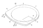
このディスクカートリッジ1を構成するカートリッジ本体5は、図1乃至図3に示すように、このディスクカートリッジ1が装脱されるディスク記録及び/又は再生装置への挿入端側となる一側面である前面側を円弧状部7として形成している。この円弧状部7は、図3に示すように、カートリッジ本体5のディスク収納部6に収納された光ディスク2の中心を中心P0として半径R1を一定にしたほぼ半円の円弧状に形成されている。すなわち、円弧状部7は、カートリッジ本体5に収納された光ディスク2の半円に相当する部分と対向するような半円として形成されている。
As shown in FIGS. 1 to 3, the cartridge
カートリッジ本体5の円弧状部7に連続する相対向する側面は、互いに平行な側面8,9として形成され、円弧状部7と対向する背面側は、なだらかに湾曲して連続した湾曲部10として形成されている。すなわち、カートリッジ本体5の背面側は、カートリッジ本体5の前面側に構成された半円状の円弧状部7より大きな半径、すなわち、円弧状部7より曲率が小さい湾曲部10とされている。
Opposite side surfaces that are continuous with the arc-
本発明に係るディスクカートリッジ1は、挿入端側となる一の側面である前面を他の面に比し大きく湾曲したほぼ半円の円弧状部7としているので、カートリッジ挿脱口を介してスロットイン方式により装脱が行われるディスク記録及び/又は再生装置へ挿入への挿入を容易に判別できる。特に、掌内に収納できる程度に小型化したディスクカートリッジ1にあっては、手で握った感覚でも挿入方向の識別を行うことができるので、誤挿入を防止して正確にディスク記録及び/又は再生装置に装着することも可能となる。しかも、このディスクカートリッジ1は、後述するように、スロットイン方式のディスク記録及び/又は再生装置へ挿入操作が容易となるばかりか、確実な挿入操作を実現できる。
In the
本発明に係るディスクカートリッジ1は、挿入端側をほぼ半円の円弧状部7とし、さらに加えて円弧状部7と対向する背面も湾曲部10としているので、収納する光ディスク2に対し一層の小型化が実現されている。
The
ここで、互いに突き合わせ結合されてカートリッジ本体5を構成する上下ハーフ3,4を具体的に説明する。
Here, the upper and
ここで用いられる上下ハーフ3,4は、ポリカーボネート樹脂やABS樹脂等の合成樹脂材料をモールド成型して形成される。
The upper and
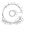
カートリッジ本体5の下面側を構成する下ハーフ4の中央部には、図4及び図5に示すように、カートリッジ本体5に収納した光ディスク2の中心部に形成したセンター穴11及びその周縁を外方に臨ませる円形のディスク駆動用開口部12が形成されている。このディスク駆動用開口部12には、ディスクカートリッジ1が装着されるディスク記録及び/又は再生装置側に設けられたディスク回転駆動機構の一部を構成する例えばターンテーブルが進入する。ディスクカートリッジ1に収納された光ディスク2は、ディスク駆動用開口部12を介してカートリッジ本体5内に進入するターンテーブルに装着されて回転駆動される。
As shown in FIGS. 4 and 5, the center hole 11 formed at the center of the
また、下ハーフ4には、図2乃至図5に示すように、記録及び/又は再生用開口部を構成するヘッド部用開口部13が形成されている。ヘッド部用開口部13は、カートリッジ本体5の一方の側面8側に位置し、ディスク駆動用開口部12に近接した位置から側面8に亘って矩形状に形成されている。すなわち、ヘッド部用開口部13は、カートリッジ本体5に収納された光ディスク2の信号記録領域の一部を内外周に亘って外方に臨ませる足る大きさの矩形状に形成されている。ここで、ヘッド部用開口部13は、図4に示すように、一方の側面8に位置するカートリッジ本体5の外周縁側を開放して形成されている。このように、ヘッド部用開口部13のカートリッジ本体5の外周縁側が開放されることにより、光ディスク2の最外周位置までヘッド部の走査領域とすることができるので、光ディスク2の信号記録領域を大きくでき、光ディスク2の記録容量を大きくすることができる。また、ヘッド部用開口部13は、ディスク駆動用開口部12に連続することなく、図4及び図5に示すようにディスク駆動用開口部12との間に連設部14を残して形成されているので、下ハーフ4の機械的強度を維持することができる。
Further, as shown in FIGS. 2 to 5, the
下ハーフ4に突き合わせ結合されてカートリッジ本体5の上面側を構成する上ハーフ3の光ディスク2と対向する面は、図1に示すように、開口部等が設けられることなく平坦な面とされている。
The surface facing the
そして、上下ハーフ3,4の突き合わせ面側の外周囲には、互いに突き合わせ結合されることによってカートリッジ本体5の外周壁15を構成する外周壁形成壁16,17が立ち上がり形成されている。各外周壁形成壁16,17は、図5及び図6に示すように、上下ハーフ3,4の外周縁に沿って形成されている。各外周壁形成壁16,17のうち、上下ハーフ3,4の半円の円弧状部7を構成する領域に位置する部分の突き合わせ面側には、相対係合する複数の係合凹部18と係合突部19とが形成されている。これら係合凹部18及び係合突部19は、円弧状部7の最も突出した左右方向の中央位置に一対設け、これら係合凹部18及び係合突部19を中心にして左右に対称に2組ずつ設けられている。
Outer peripheral
ここで、係合凹部18は、上ハーフ3側に設けられ、係合突部19は、下ハーフ4側に設けられる。係合凹部18は、図7に示すように、上ハーフ3側の外周壁形成壁16の内周面側を切り欠くことによって形成されている。また、係合突部19は、下ハーフ4側の外周壁形成壁17の先端部に突設されている。そして、係合突部19の先端部には、図7に示すように、上下ハーフ3,4を結合するための溶着部を構成する溶着用リブ20が突設されている。
Here, the
なお、上下ハーフ3,4の湾曲部10を構成する領域に位置する外周壁形成壁16,17の先端部側にも、図8に示すように、相対係合する係合凹部21及び係合突部22が形成されている。係合凹部21は、上ハーフ3側に設けられて、係合突部22は、下ハーフ4側に設けられている。そして、係合凹部21は、上ハーフ3側の外周壁形成壁16の内周面側を切り欠くことによって形成され、係合突部22は、下ハーフ4側の外周壁形成壁17の先端部に突設されている。そして、係合突部22の先端部には、図8に示すように、上下ハーフ3,4を結合するための溶着部を構成する溶着用リブ23が突設されている。溶着用リブ23は、図5に示すように、係合突部22の先端に適宜間隔を隔て複数設けられている。
In addition, as shown in FIG. 8, the
各外周壁形成壁16,17は、係合凹部18,21と係合突部19,22とを相対係合して突き合わせ、次いで、溶着用リブ20,23を溶融することにより、図9及び図10に示すように、互いに溶着されてカートリッジ本体5の外周壁15を構成する。外周壁形成壁16,17の溶着は、溶着用リブ20,23に超音波を印加し、これら溶着用リブ20,23を溶融することによって行われる。
The outer peripheral
また、上下ハーフ3,4の相対向する内面側であって、カートリッジ本体5の背面側の湾曲部10を構成する側に位置して、互いに突き合わされて円形のディスク収納部6の一部を構成する収納部形成壁24,25が形成されている。これら収納部形成壁24,25は、図5及び図6に示すように、カートリッジ本体5の前面側の円弧状部7を構成する外周壁形成壁16,17に一連に連続してこのカートリッジ本体5に収納される光ディスク2の外周を囲む円形のディスク収納部6の一部を構成するように、カートリッジ本体5の湾曲部10を構成する外周壁15を構成する外周壁形成壁16,17の内方側に位置して形成されている。
Further, the inner and
本発明に係るディスクカートリッジ1は、カートリッジ本体5の外周壁15の一部を利用してディスク収納部6を構成するようにしているので、収納する光ディスク2に対し一層の小型化を図ることができる。
In the
ディスク収納部6を構成する収納部形成壁24,25とカートリッジ本体5の前面側の円弧状部7を構成する外周壁形成壁16,17は、ディスク収納部6に収納された光ディスク2の外周囲を囲むように形成されているので、ディスク収納部6に収納された光ディスク2の収納位置を規制するとともに、ディスク収納部6への異物の進入を防止して光ディスク2の保護を図るディスク保護壁としても機能する。
The storage
さらに、本発明に係るディスクカートリッジ1において、カートリッジ本体5を構成する上下ハーフ3,4は、外周縁側から収納部形成壁24,25側に偏倚した内方側の位置であって、ヘッド部用開口部13の一方の側に近接した部分が溶着されて一体化される。
Further, in the
すなわち、図5に示すように、下ハーフ4に形成した収納部形成壁25のヘッド部用開口部13の一側に臨む一端部側の突き当て面に先端先細り状とした溶着用リブ26が設けられている。
That is, as shown in FIG. 5, the
さらに、図5及び図11に示すように、下ハーフ4の収納部形成壁25とカートリッジ本体5の湾曲部10を構成する背面側の外周壁形成壁17により囲まれた左右の領域のうち、ヘッド部用開口部13が形成された側に位置する一方の領域内に位置して、筒状の結合ピン27が形成されている。この結合ピン27の先端面には、先端先細り状とした溶着用リブ28が突設されてる。
Further, as shown in FIGS. 5 and 11, of the left and right regions surrounded by the housing
さらにまた、下ハーフ4の結合ピン27が形成された領域内であって、収納部形成壁25に設けた溶着用リブ26と結合ピン27との間に位置して、図5及び図11に示すように、L字状の突き合わせ片29が設けられている。この突き合わせて片29の先端面にも、先端先細り状とした溶着用リブ30が突設されてる。また、突き合わせ片29は、収納部形成壁25の外周面側に連結して形成されているので、収納部形成壁25の強度を向上することができる。ところで、小型のディスクカートリッジ1においては、カートリッジ自体の小型化を図るため、カートリッジ本体5を構成する要素も肉薄に形成される。その結果、収納部形成壁25も肉薄に形成されるが、この収納部形成壁25を外周面側から支持するように突き合わせ片29が形成されることにより、収納部形成壁25の機械的強度を向上し高精度に形成できる。特に、収納部形成壁25のヘッド部用開口部13に臨む側は、開放された状態にあるので、肉薄に形成されることにより容易に撓み変形してしまうが、突き合わせ片29により支持されることにより、撓み変形が防止でき、上ハーフ3側の収納部形成壁24と突き合わせるときに正確な位置合わせを行うことができる。
Further, in the region where the
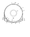
一方、下ハーフ4と突き合わせ結合される上ハーフ3側には、図6及び図12に示すように、下ハーフ4に設けた結合ピン27の先端部が当接結合される結合受けピン31が形成されている。さらに、上ハーフ3には、図6及び図12に示すように、下ハーフ4側に設けた突き合わせ片29と突き合わせ結合される突き合わせ結合片32が形成されている。この突き合わせ結合片32も突き合わせ片29と同様に、収納部形成壁24の外周面側に連結して形成されているので、肉薄に形成される収納部形成壁24の機械的強度を向上し高精度に形成できる。この収納部形成壁24においても、ヘッド部用開口部13に臨む側は、開放された状態にあるので、肉薄に形成されることにより容易に撓み変形してしまうが、突き合わせ結合片32により支持されることにより、撓み変形が防止でき、下ハーフ4側の収納部形成壁25と突き合わせるときに正確な位置合わせが可能となる。
On the other hand, as shown in FIGS. 6 and 12, on the side of the
なお、下ハーフ4の収納部形成壁25側に形成した溶着用リブ26が溶着される上ハーフ3側の収納部形成壁24の先端面は平坦な面とされている。
In addition, the front end surface of the storage
上ハーフ3側に形成される結合受けピン31及び突き合わせ結合片32は、下ハーフ4側の結合ピン27及び突き合わせ片29と結合されるものであり、上ハーフ3の収納部形成壁24とカートリッジ本体5の湾曲部10を構成する背面側の外周壁形成壁16により囲まれた左右の領域のうち、ヘッド部用開口部13側に位置する一方の領域内に位置して形成される。
また、下ハーフ4の上ハーフ3と対向する内面側には、図5及び図11に示すように、ディスク駆動用開口部12を囲むようにして、リング状のディスク支持突部33が形成されている。また、上ハーフ4の下ハーフ4と対向する内面側にも、図6に示すように、リング状のディスク支持突部34が形成されている。このディスク支持突部34は、下ハーフ4側のディスク支持突部33に対向する位置に設けられる。これらディスク支持突部33,34は、ディスク収納部6に収納された光ディスク2の内周側の非信号記録領域を支持し、信号記録領域が直接上下ハーフ3,4の内面に接触することを防止し、光ディスク2の保護を図るようにしている。
Further, as shown in FIGS. 5 and 11, a ring-shaped
なお、上ハーフ3側に形成されるディスク支持突部34は、下ハーフ4側のディスク支持突部33よりやや小径に形成されている。
The
さらに、下ハーフ4には、このディスクカートリッジ1をディスク記録及び/又は再生装置に装着したとき、装置側に設けた位置決めピンが係合する第1及び第2の位置決め孔35,36が設けられている。これら位置決め孔35,36は、図3及び図4に示すように、湾曲部10を構成する背面側の両側に位置して設けられる。すなわち、第1及び第2の位置決め孔35,36は、図5に示すように、収納部形成壁25とカートリッジ本体5の湾曲部10を構成する背面側の外周壁形成壁17により囲まれた左右の各領域にそれぞれ設けられている。なお、第2の位置決め孔36は、位置決めピンの係合位置を調整するため、図3及び図4に示すように、カートリッジ本体5の各側面8,9に亘る幅方向を長径とする長孔として形成されている。
Further, the
そして、下ハーフ4の内面側には、図5及び図11に示すように、第1の位置決め孔35を囲むようにして筒状の第1の係合突部37が突設され、第2の位置決め孔36を囲むようにして筒状の突き当て突部38が突設されている。さらに、収納部形成壁25と外周壁形成壁17とに囲まれた領域のうち第2の位置決め孔36が設けられた領域内に位置して第2の係合突部39が突設されている。この第2の係合突部39も、筒状に形成されている。
As shown in FIGS. 5 and 11, a cylindrical first engaging
ところで、第2の係合突部39は、図5に示すように、第2の位置決め孔36が設けられる位置よりカートリッジ本体5の他方の側面9を構成する外周壁形成壁17側に位置して形成されている。すなわち、第2の係合突部39は、図5に示すように、第1の位置決め部を構成する第1の係合突部37に対し、第2の位置決め孔36よりさらに離間した位置に設けられている。
By the way, as shown in FIG. 5, the second engaging
ここで、第1の係合突部37は、上下ハーフ3,4の突き合わせ位置を位置決めする第1の位置決め部を構成し、第2の係合突部39は、第2の位置決め部を構成する。
Here, the
一方、上ハーフ3の内面側には、図6に示すように、下ハーフ4に設けた第1の係合突部37と相対係合する第1の係合受け部40が設けられるとともに、突き当て突部38に突き当てられる筒状の支持突部41が設けられ、さらに、第2の係合突部39と相対係合する第2の係合受け部42とが設けられている。
On the other hand, on the inner surface side of the
なお、下ハーフ4側の第1及び第2の係合突部37,39は、図11に示すように、外周壁形成壁17の先端より突出する高さに形成されることにより、各外周壁形成壁16,17を突き合わせて上下ハーフ3,4を結合したとき、外周壁形成壁16と等しい高さに形成された上ハーフ3側の第1及び第2の係合受け部40,42に係合される。
The first and second engaging
ところで、上ハーフ3側に設けられる第1の係合受け部40及び結合受けピン31は、図6に示すように、収納部形成壁24とカートリッジ本体5の湾曲部10を構成する背面側の外周壁形成壁16により囲まれた左右の各領域にそれぞれ設けられている。そして、第2の係合受け部42は、支持突部41が設けられた領域内に位置し、図6に示すように、支持突部41が設けられる位置よりカートリッジ本体5の他方の側面9を構成する外周壁形成壁16側に位置して形成されている。
By the way, the first
ここで、下ハーフ4側の第1の係合突部37と上ハーフ3側の第1の係合受け部40は、相対係合されたとき、上下ハーフ3,4の突き合わせ基準位置を構成する。すなわち、上ハーフ3は、下ハーフ4に設けた第1の係合突部37を係合基準位置として下ハーフ4に結合される。したがって、第1の係合突部37と第1の係合受け部40とは、図13に示すように、互いに密嵌するような径をもって形成されている。すなわち、筒状の第1の係合突部37の外径と、第1の係合突部37の先端部が係合する第1の係合受け部40の内周径とは、ほぼ等しい径とされている。
Here, when the
なお、第1の係合受け部40の内部には、図12及び図13に示すように、第1の係合突部37の先端部が当接する当接段部43が形成されている。第1の係合突部37は、先端部を当接段部43に当接させて第1の係合受け部40に係合される。第1の係合受け部40は、内部に当接段部43を形成しているので、上ハーフ3の平面側に位置する基部側の肉厚を厚くでき、機械的な強度を大きくすることができる。
As shown in FIGS. 12 and 13, a
また、第2の係合受け部42は、カートリッジ本体5の各側面8,9に亘る図6中矢印X1方向の幅方向を長径とした楕円形に形成され、第1の係合突部37と第1の係合受け部40とを基準として上下ハーフ3,4を突き合わせたとき、第2の係合突部39の幅方向の係合位置を調整可能としている。
Further, the second
なお、第1及び第2の係合突部37,39は、図11に示すように、外周壁形成壁17の先端より突出する高さに形成されることにより、各外周壁形成壁16,17を突き合わせて上下ハーフ3,4を結合したとき、外周壁形成壁16と等しい高さに形成された第1及び第2の係合受け部40,42に係合する。
As shown in FIG. 11, the first and second engaging
上述のように構成された上下ハーフ3,4を突き合わせ結合してカートリッジ本体5を形成するには、下ハーフ4を位置決め治具に位置決め支持し、図13に示すように、下ハーフ4側の第1の係合突部37に上ハーフ3側の第1の係合受け部40を相対係合するとともに、下ハーフ4側の第2の係合突部39に上ハーフ3側の第2の係合受け部42を相対係合し、さらに、図9に示すように下ハーフ4側の複数の係合突部19に上ハーフ3側の複数の係合凹部18をそれぞれ相対係合して互いの外周壁形成壁16,17が突き合わせられる。
To form the
ところで、上ハーフ3側の係合凹部18が相対係合する下ハーフ4側の係合突部19のうち、円弧状部7の最も突出した中央位置に設けられた係合突部19Aは、上下ハーフ3,4を突き合わせ結合するとき、円弧状部7の円弧に沿う図14中矢印X2方向の位置決めを図る第3の位置決め部として機能するように形成されている。すなわち、第3の位置決め部を構成する係合突部19Aは、上ハーフ3側の係合凹部18と相対係合したとき、間隙が小さくなるように形成されている。すなわち、第3の位置決め部を構成する係合突部19Aとこの係合突部19に係合する係合凹部18Aとは、図15に拡大して示すように、相対係合したときの間隙D1が小さくなるように精度良く形成される。すなわち、この係合突部19Aと、この係合突部19に係合する係合凹部18Aは、互いに密接して係合し得るように、ほぼ同一の幅W1,W2をもって形成されている。このように、第3の位置決め部を構成する係合突部19Aに相対する係合凹部18Aが密接して係合するので、上下ハーフ3,4は、円弧状部7の円弧に沿う方向の位置決めが図られて結合される。
Meanwhile, among the engaging
なお、係合突部19Aと係合凹部18Aは、逆の関係で設けるようにしてもよい。すなわち、上ハーフ3側に係合突部19Aを設け、下ハーフ4側に係合凹部18Aを設けるようにしてもよい。この場合には、下ハーフ4側の係合凹部18Aが第3の位置決め部を構成する。
Incidentally, the engaging
上述のように、上下ハーフ3,4は、第1の係合突部37と第1の係合受け部40を突き合わせ基準位置として突き合わせられる。そして、第2の係合突部39と第2の係合受け部42とが相対係合することにより、図14中矢印X1方向の幅方向と直交する矢印Y1方向のカートリッジ本体5の前後方向に位置決めが図られ、さらに、第3の位置決め部を構成する一対の係合凹部18Aと係合突部19Aが相対係合することにより、記録及び/又は再生装置への挿入端側となる円弧状部7側の突き合わせ位置の位置決めが図られる。
As described above, the upper and
このように上下ハーフ3,4が位置決めされて突き合わせられるとき、上下ハーフ3,4に設けた収納部形成壁24,25が突き合わせられ、さらに、上ハーフ3に設けた結合受けピン31と下ハーフ4に設けた結合ピン27とが突き合わせられ、さらに、上ハーフ3に設けた突き合わせ結合片32に下ハーフ4に設けた突き合わせ片29とが突き合わせられる。
When the upper and
互いに位置決めが図られて突き合わせられた上下ハーフ3,4は、超音波溶着装置を用いて、下ハーフ4側の外周壁形成壁17に形成した係合突部19の先端部に設けられた溶着用リブ20、収納部形成壁25に設けた溶着用リブ26、結合ピン27の先端面に形成した溶着用リブ28、突き合わせ片29の先端面に設けた溶着用リブ30に超音波を印加して溶融することにより、各溶着用リブ20,28,30が溶融され、上下ハーフ3,4に形成した外周壁形成壁16,17が結合され、収納部形成壁24,25の一部が結合し、さらに、互いに突き合わせられた結合ピン27と結合受けピン31との間が結合され、突き合わせ片29と突き合わせ結合片32との間が結合されて一体化されてカートリッジ本体5を構成する。
The upper and
なお、収納部形成壁24,25との間を結合する溶着用リブ26、結合ピン27と結合受けピン31との間を結合する溶着用リブ28、突き合わせ片29と突き合わせ結合片32との間を結合する溶着用リブ30は、上述の例を逆に設けるようにしてもよい。
In addition, the
上述したように、本発明において、上下ハーフ3,4は、カートリッジ本体5の湾曲部10とされた背面側の両側に設けられた第1及び第2の位置決め部と、前面側の円弧状部7の中央部に設けられた第3の位置決め部の3点で位置決めがされて突き合わせ結合されてなるので、上下ハーフ3,4の位置ずれを小さくしてカートリッジ本体5を高精度に形成できる。特に、第1〜第3の位置決め部は、カートリッジ本体5の外周側に位置し、互いの位置間を大きく隔て配置されているので、上下ハーフ3,4の位置ずれを一層小さくしてカートリッジ本体5を高精度に形成できる。その結果、このカートリッジ本体5を用いたディスクカートリッジ1は、高精度なものとなり、記録及び/又は再生装置への装脱も円滑に行うことが可能となるばかりか、外観も良好なものとなる。
As described above, in the present invention, the upper and
また、本発明に係るディスクカートリッジ1は、下ハーフ4側の第2の位置決め部を構成する第2の係合突部39を第1の係合突部37に対し大きく離間して設けるようにしているので、上下ハーフ3,4の突き合わせ位置の位置ずれの発生を一層小さくすることができる。特に、第1の係合突部37と第2の係合突部39との間に位置する第2の位置決め孔36の周囲に設けられた突き当て突部38と筒状の支持突部41との当接位置のずれを小さくし、確実な突き合わせを実現することができる。
Further, in the
さらに、本発明に係るディスクカートリッジ1においては、上下ハーフ3,4が位置ずれの発生を抑えて結合されるので、上下ハーフ3,4に設けられる収納部形成壁24,25も位置ずれを抑えて突き合わせることができ、ディスク収納部6を高精度に形成できる。その結果、ディスク収納部6内に光ディスク2に損傷を与えてしまうような突起等の発生を抑えることができ、光ディスク2の確実な保護を図ることができる。
Further, in the
そして、本発明に係るディスクカートリッジ1においては、カートリッジ本体5の外周縁側からディスク収納部6側に偏倚した内方側の位置であって、カートリッジ本体5の外周縁側を開放して形成されたヘッド部用開口部13の一方の側に近接した位置が溶着されているので、ヘッド部用開口部13の近傍を強固に結合でき、収納する光ディスク2の信号記録領域を拡大するため、カートリッジ本体5の外周縁側を開放してヘッド部用開口部13を形成しても、上下ハーフ3,4の確実な結合が実現される。
In the
さらに、本発明に係るディスクカートリッジ1においては、収納部形成壁24,25のヘッド部用開口部13に臨む開放された状態にある部分が溶着されているので、収納部形成壁24,25を肉薄に形成しても、撓み変形が防止でき、これら収納部形成壁24,25を突き合わせて形成されるディスク収納部6の変形を防止でき、ディスク収納部6に収納した光ディスク2の確実な保護を図ることができる。
Furthermore, in the
特に、収納部形成壁24,25は、突き合わせ片29及び突き合わせ結合片32により支持され、肉薄に形成しても撓み変形が防止でき、互いの突き合わせを高精度に行うことができ、これら収納部形成壁24,25を突き合わせて形成されるディスク収納部6を高精度に形成することができる。
In particular, the storage
さらにまた、本発明に係るディスクカートリッジ1においては、カートリッジ本体5の外周壁15を構成する外周壁形成壁16,17がディスク収納部6を構成するようにしているので、ディスクカートリッジ1の一層の小型化が実現されている。
Furthermore, in the
上述のように構成されたカートリッジ本体5には、図1、図2及び図3に示すように、ヘッド部用開口部13を開閉するシャッタ部材45が取り付けられる。このシャッタ部材45は、薄い金属板を打ち抜き折り曲げて形成され、若しくは合成樹脂材料を成形して形成されたものであって、図2及び図3及びに示すように、ヘッド部用開口部13を閉塞する足るに大きさの矩形状に形成したされ平板状のシャッタ部46と、このシャッタ部46の基板部側に形成された断面コ字状に形成されたカートリッジ支持部47とを備える。シャッタ部46の先端部には、カートリッジ本体5側に取り付けられるシャッタガイド部材48により支持されるガイド支持部49が設けられている。
As shown in FIGS. 1, 2, and 3, a
このシャッタ部材45は、カートリッジ本体5を構成する上ハーフ3側に形成されたスライドガイド部51をカートリッジ支持部47により支持することによってヘッド部用開口部13を開閉する図1及び図2中矢印A方向又は矢印B方向に移動可能に支持される。このとき、シャッタ部材45は、ガイド支持部49がカートリッジ本体5側に取り付けられたシャッタガイド部材48により支持されるので、シャッタ部46のカートリッジ本体5からの浮き上がりが防止でき、安定した移動が実現される。
The
なお、シャッタ部材45は、図示しないが、カートリッジ本体5内に配設した捩りコイルバネ等の付勢部材を介してヘッド部用開口部13を閉塞する方向の図1及び図2中矢印B方向に移動付勢され、ディスク記録及び/又は再生装置に装着されない保管等に確実にヘッド部用開口部13を閉塞するようにしている。
The
ところで、本発明において、カートリッジ本体5の外周縁側からディスク収納部6側に偏倚した内方側の位置であって、カートリッジ本体5の外周縁側を開放して形成されたヘッド部用開口部13の一方の側の位置は、シャッタ部材45が移動する領域内であり、ヘッド部用開口部13を開放した位置に移動されたシャッタ部材45が位置する領域である。
By the way, in the present invention, the position of the
上述したディスクカートリッジ1は、ヘッド部用開口部13を閉塞するためのシャッタ部材45を備えているが、本発明に係るディスクカートリッジは、シャッタ部材を設けることなくヘッド部用開口部13を開放したままにしたものであってもよい。
The
シャッタ部材を設けることなく構成されたディスクカートリッジ101は、図16及び図17に示すように構成される。
A
このディスクカートリッジ101は、基本的な構成を上述したディスクカートリッジ1と共通にするので、共通する部分には共通の符号を付して詳細な説明は省略する。
Since the basic configuration of the
シャッタ部材を設けることなく構成された本発明に係るディスクカートリッジ101も前述したディスクカートリッジ1と同様に、上下一対のハーフ3,4を突き合わせ結合したカートリッジ本体5を備え、このカートリッジ本体5内に光ディスク2を回転可能に収納している。
Similarly to the
このディスクカートリッジ101を構成するカートリッジ本体5は、図16及び図17に示すように、このディスクカートリッジ101が装脱されるディスク記録及び/又は再生装置への挿入端側となる一側面である前面側を円弧状部7として形成している。
As shown in FIGS. 16 and 17, the cartridge
カートリッジ本体5の円弧状部7に連続する相対向する側面は、互いに平行な側面8,9として形成され、円弧状部7と対向する背面側は、なだらかに湾曲して連続した湾曲部10として形成されている。すなわち、カートリッジ本体5の背面側は、カートリッジ本体5の前面側に構成された半円状の円弧状部7より大きな半径、すなわち、円弧状部7より曲率が小さい湾曲部10とされている。
Opposite side surfaces that are continuous with the arc-shaped
このディスクカートリッジ101においても、カートリッジ本体5の下面側を構成する下ハーフ4の中央部には、図17に示すように、カートリッジ本体5に収納した光ディスク2の中心部に形成したセンター穴11及びその周縁を外方に臨ませる円形のディスク駆動用開口部12が形成されている。
Also in this
また、下ハーフ4には、図17に示すように、記録及び/又は再生用開口部を構成するヘッド部用開口部13が形成されている。ヘッド部用開口部13は、カートリッジ本体5の一方の側面8側に位置し、ディスク駆動用開口部12に近接した位置から側面8に亘って矩形状に形成されている。すなわち、ヘッド部用開口部13は、カートリッジ本体5に収納された光ディスク2の信号記録領域の一部を内外周に亘って外方に臨ませる足る大きさの矩形状に形成されている。このヘッド部用開口部13も、図17に示すように、一方の側面8に位置するカートリッジ本体5の外周縁側を開放して形成されている。また、ヘッド部用開口部13は、ディスク駆動用開口部12に連続することなく、ディスク駆動用開口部12との間に連設部14を残して形成されているので、下ハーフ4の機械的強度を維持することができる。
Further, as shown in FIG. 17, the
ところで、本例のディスクカートリッジ101は、ヘッド部用開口部13を開閉するシャッタ部材を設けることなく構成されているので、カートリッジ本体の5の下面を構成する下ハーフ4の外方側の面も、図17に示すように、ディスク駆動部用開口部12及びヘッド部用開口部13が形成された部分を除いて平坦な面として形成されている。
By the way, the
このディスクカートリッジ101においても、カートリッジ本体5の外周縁側からディスク収納部6側に偏倚した内方側の位置であって、カートリッジ本体5の外周縁側を開放して形成されたヘッド部用開口部13の一方の側に近接した位置が溶着されているので、ヘッド部用開口部13の近傍を強固に結合でき、収納する光ディスク2の信号記録領域を拡大するため、カートリッジ本体5の外周縁側を開放してヘッド部用開口部13を形成しても、上下ハーフ3,4の確実な結合が実現される。
Also in the
ところで、図16及び図17に示すディスクカートリッジ101に設けたヘッド部用開口部13は、前述したディスクカートリッジ1に形成したヘッド部用開口部13よりも大きく形成されている。本例のディスクカートリッジ101に設けたヘッド部用開口部13は、カートリッジ本体5の挿入端側から背面側に至る前後方向の中心より挿入端側の領域を大きく開放して形成されている。これは、このディスクカートリッジ101に収納した光ディスク2の信号記録領域を光ビームにより走査する光ヘッド部をカートリッジ本体5内に進入させ、光ディスク2に近接させるようにするためである。
Incidentally, the
このように、光ヘッドを光ディスク2に近接させることができるので、開口数(NA)の大きな対物レンズを用いた光ヘッド部により光ディスク2の走査を行うことができるので、光ディスク2の高密度化が図られ、さらに、このディスクカートリッジ101を用いる記録及び/又は再生装置の薄型化も可能となる。
As described above, since the optical head can be brought close to the
上述した例では、ディスクとして光ディスク2をカートリッジ本体5に収納した例を挙げて説明したが、本発明は、光ディスクに限られるものではなく、磁気ディスクを含むその他のディスクを収納したディスクカートリッジに適用した場合にも、上述したような利点を得ることができるものである。
In the example described above, an example was described in which housing the
1 ディスクカートリッジ、 2 光ディスク、 3 上ハーフ、 4 下ハーフ、 5 カートリッジ本体、 6 ディスク収納部、 7 円弧状部、 12 ディスク駆動用開口部、 13 ヘッド部用開口部、 16,17 外周壁形成壁、 18 係合凹部、 19 係合突部、 20 溶着用リブ、 24,25 収納形成壁、 27 結合ピン、 28 溶着用リブ、29 突き合わせ片、 30 溶着用リブ、31 結合受けピン、 32 突き合わせ結合片、33,34 ディスク支持突部、35 第1の位置決め孔、36 位置決め孔、37 第1の係合突部、38 突き当て突部、39 第2の係合突部、40 第1の係合受け部、41 支持突部、42 第2の係合受け部、43 当接段部、45 シャッタ部材
DESCRIPTION OF
Claims (2)
上記カートリッジ本体が、ディスク記録及び/又は再生装置への挿入端側が上記ディスクの回転中心から所定の半径とされて上記ディスク収納部の一部を構成するほぼ半円状の円弧状部とされるとともに、この円弧状部と対向する背面側が上記挿入端側よりも半径の大きな湾曲部として形成され、
上記カートリッジ本体を構成する上記上ハーフには、外周縁に沿って全域に亘り上端縁に多数個の係合部を設けた外周壁形成壁が形成され、上記湾曲部を構成する側の上記外周壁形成壁の内側に位置する内面に上記円弧状部を構成する側の上記外周壁形成壁に連続して全体で環状壁を構成する上記ディスクの回転中心からの半径が等しい半円状の収納部形成壁が形成され、この収納部形成壁と上記外周壁形成壁との間の領域内面に上記湾曲部の両側に位置して第1の位置決め係合部と第2の位置決め係合部とが形成されるとともに上記円弧状部を構成する上記外周壁形成壁に設けた上記係合部のほぼ中央位置に位置する係合部が第3の位置決め係合部として構成してなり、
上記カートリッジ本体を構成する上記下ハーフには、外周縁に沿って上端縁に上記上ハーフ側の上記係合部と相対係合される複数個の係合部を設けた外周壁形成壁が形成され、中央部に上記ディスクを回転操作するディスク回転駆動機構の少なくとも一部が臨むディスク駆動用開口部が形成されるとともに、上記円弧状部と上記湾曲部に連続する相対向する互いに平行な側面の一方側に上記外周壁形成壁を開放しかつ上記ディスク駆動用開口部との間に連設部を介して上記ディスクの一部を内外周に亘って外方に臨ませる記録及び/又は再生用開口部が設けられ、上記湾曲部を構成する側の上記外周壁形成壁の内側に位置する内面に上記円弧状部を構成する一方側の上記外周壁形成壁から上記記録及び/又は再生用開口部の開口縁までの間において全体で一部を切り欠いた環状壁を構成する上記ディスクの回転中心からの半径が等しい半円状の収納部形成壁が形成され、この収納部形成壁と上記外周壁形成壁との間の領域内面に上記湾曲部の両側に位置し上記上ハーフ側の上記第1の位置決め係合部と第2の位置決め係合部と相対係合される第1の位置決め係合部と第2の位置決め係合部とが形成されるとともに上記円弧状部を構成する上記外周壁形成壁に設けた上記係合部のほぼ中央位置に位置する係合部が上記上ハーフ側の上記第3の位置決め係合部と相対係合される第3の位置決め係合部として構成され、上記収納部形成壁の上記記録及び/又は再生用開口部側の端部近傍の側面に上記上ハーフに相対して形成した突き合わせ片と突き合わされる突き合わせ片を一体に形成してなり、
上記カートリッジ本体は、上記上ハーフと上記下ハーフとが、上記第1の位置決め係合部乃至上記第3の位置決め係合部により位置決めして組み合わされることによりそれぞれの上記外周壁形成壁と上記収納部形成壁が突き合わされ、これら外周壁形成壁と収納部形成壁に設けられて相対係合した上記係合部を溶着するとともに、上記ディスク駆動用開口部の近傍位置において上記突き合わせ片を溶着することにより一体化されて構成されることを特徴とするディスクカートリッジ。 A disc is rotatably accommodated in a disc storage portion configured inside a cartridge body in which a pair of upper and lower halves made of synthetic resin are butted and joined.
The cartridge main body has a substantially semicircular arc-shaped portion constituting a part of the disc storage portion with the insertion end side to the disc recording and / or reproducing apparatus having a predetermined radius from the rotation center of the disc. And the back side facing this arcuate part is formed as a curved part having a larger radius than the insertion end side,
The upper half constituting the cartridge main body is formed with an outer peripheral wall forming wall provided with a plurality of engaging portions at the upper end edge along the entire outer peripheral edge, and the outer periphery on the side constituting the curved portion A semicircular storage having an equal radius from the center of rotation of the disk that forms an annular wall as a whole in succession to the outer peripheral wall forming wall on the inner surface located on the inner side of the wall forming wall. A first positioning engagement portion and a second positioning engagement portion located on both sides of the curved portion on the inner surface of the region between the storage portion forming wall and the outer peripheral wall forming wall. Is formed, and the engaging portion located at substantially the center position of the engaging portion provided on the outer peripheral wall forming wall constituting the arc-shaped portion is configured as a third positioning engaging portion,
The lower half constituting the cartridge body is formed with an outer peripheral wall forming wall provided with a plurality of engaging portions which are engaged with the engaging portions on the upper half side along the outer peripheral edge at the upper end edge. And a disk drive opening that faces at least a part of the disk rotation drive mechanism for rotating the disk is formed at the center, and the mutually parallel side surfaces that are continuous with the arcuate portion and the curved portion are opposed to each other. Recording and / or reproduction in which the outer peripheral wall forming wall is opened on one side of the disc and a part of the disc is exposed to the outside over the inner and outer peripheries via a connecting portion between the disc driving opening For recording and / or reproduction from the outer peripheral wall forming wall on one side constituting the arcuate portion on the inner surface located inside the outer peripheral wall forming wall on the side constituting the curved portion. Between the opening edge of the opening A semicircular storage portion forming wall having the same radius from the center of rotation of the disk constituting the annular wall partially cut out is formed between the storage portion forming wall and the outer peripheral wall forming wall. The first positioning engagement portion and the second positioning engagement portion that are located on both sides of the curved portion on the inner surface of the region and are engaged with the first positioning engagement portion and the second positioning engagement portion on the upper half side. The engaging portion that is formed at the substantially central position of the engaging portion provided on the outer peripheral wall forming wall that forms the arc-shaped portion and the positioning engaging portion is formed on the upper half side. A third positioning engagement portion that is relatively engaged with the engagement portion, and is opposed to the upper half on the side surface of the storage portion forming wall in the vicinity of the end on the recording and / or reproducing opening side. The butt piece to be abutted with the formed butt piece is integrally formed. Now,
The cartridge body is configured such that the upper half and the lower half are positioned and combined by the first positioning engagement portion to the third positioning engagement portion, and the outer peripheral wall forming wall and the storage portion are combined. The part forming walls are abutted, and the engaging parts provided on the outer peripheral wall forming wall and the storage part forming wall and engaged with each other are welded together, and the butt pieces are welded in the vicinity of the opening for driving the disk. A disc cartridge characterized by being integrated with each other .
Priority Applications (3)
| Application Number | Priority Date | Filing Date | Title |
|---|---|---|---|
| JP2004140475A JP4363249B2 (en) | 2004-05-10 | 2004-05-10 | Disc cartridge |
| US11/125,608 US20050278730A1 (en) | 2004-05-10 | 2005-05-09 | Disc cartridge |
| CNB2005100783411A CN100358039C (en) | 2004-05-10 | 2005-05-10 | Disc cartridge |
Applications Claiming Priority (1)
| Application Number | Priority Date | Filing Date | Title |
|---|---|---|---|
| JP2004140475A JP4363249B2 (en) | 2004-05-10 | 2004-05-10 | Disc cartridge |
Publications (3)
| Publication Number | Publication Date |
|---|---|
| JP2005322345A JP2005322345A (en) | 2005-11-17 |
| JP2005322345A5 JP2005322345A5 (en) | 2006-01-05 |
| JP4363249B2 true JP4363249B2 (en) | 2009-11-11 |
Family
ID=35462032
Family Applications (1)
| Application Number | Title | Priority Date | Filing Date |
|---|---|---|---|
| JP2004140475A Expired - Fee Related JP4363249B2 (en) | 2004-05-10 | 2004-05-10 | Disc cartridge |
Country Status (3)
| Country | Link |
|---|---|
| US (1) | US20050278730A1 (en) |
| JP (1) | JP4363249B2 (en) |
| CN (1) | CN100358039C (en) |
Families Citing this family (4)
| Publication number | Priority date | Publication date | Assignee | Title |
|---|---|---|---|---|
| JP4555521B2 (en) * | 2001-09-18 | 2010-10-06 | 富士通株式会社 | Information processing apparatus and detachable unit |
| JP4424187B2 (en) * | 2004-12-09 | 2010-03-03 | ソニー株式会社 | Protective member for disk cartridge and disk cartridge |
| WO2007126127A1 (en) * | 2006-04-28 | 2007-11-08 | Kuraray Co., Ltd. | Cell culture container and method of producing the same |
| JP2010033664A (en) * | 2008-07-29 | 2010-02-12 | Hitachi-Lg Data Storage Inc | Tray of optical disk device, and optical disk device provided with the same |
Family Cites Families (14)
| Publication number | Priority date | Publication date | Assignee | Title |
|---|---|---|---|---|
| DE3363461D1 (en) * | 1982-02-10 | 1986-06-19 | Hitachi Maxell | Magnetic recording disc cartridge |
| JPS6085479A (en) * | 1983-10-14 | 1985-05-14 | Hitachi Maxell Ltd | Disk cartridge |
| JPH05166329A (en) * | 1991-12-17 | 1993-07-02 | Mitsubishi Kasei Corp | Magnetic disk cartridge |
| JPH076493A (en) * | 1993-06-21 | 1995-01-10 | Matsushita Electric Ind Co Ltd | Optical disk device and disk cartridge |
| JP3491427B2 (en) * | 1996-02-09 | 2004-01-26 | ソニー株式会社 | Disk cartridge |
| US5930090A (en) * | 1997-11-12 | 1999-07-27 | Iomega Corporation | Data cartridge with compression return spring following arcuate guide |
| JP2000048519A (en) * | 1998-07-27 | 2000-02-18 | Mitsubishi Chemicals Corp | Disk cartridge |
| JP2002124054A (en) * | 2000-10-13 | 2002-04-26 | Sony Corp | Disk cartridge and method of molding the same |
| JP2002269944A (en) * | 2001-03-14 | 2002-09-20 | Fuji Photo Film Co Ltd | Disk cartridge |
| US7017170B2 (en) * | 2001-06-29 | 2006-03-21 | Sony Corporation | Disk cartridge with inner shell supported for rotation in guide groove formed in an upper shell |
| JP2003338152A (en) * | 2002-05-20 | 2003-11-28 | Sony Corp | Information recording medium cartridge |
| JP2004133973A (en) * | 2002-10-09 | 2004-04-30 | Fuji Photo Film Co Ltd | Working method of metallic plate member of disk cartridge |
| KR101058852B1 (en) * | 2003-11-27 | 2011-08-23 | 소니 주식회사 | Disc cartridge |
| JP2005222671A (en) * | 2004-01-08 | 2005-08-18 | Sony Corp | Disk cartridge |
-
2004
- 2004-05-10 JP JP2004140475A patent/JP4363249B2/en not_active Expired - Fee Related
-
2005
- 2005-05-09 US US11/125,608 patent/US20050278730A1/en not_active Abandoned
- 2005-05-10 CN CNB2005100783411A patent/CN100358039C/en not_active Expired - Fee Related
Also Published As
| Publication number | Publication date |
|---|---|
| US20050278730A1 (en) | 2005-12-15 |
| CN1716432A (en) | 2006-01-04 |
| CN100358039C (en) | 2007-12-26 |
| JP2005322345A (en) | 2005-11-17 |
Similar Documents
| Publication | Publication Date | Title |
|---|---|---|
| KR20050073553A (en) | Disc cartridge | |
| JP4363249B2 (en) | Disc cartridge | |
| US7383559B2 (en) | Disc cartridge of reduced size | |
| JP4682515B2 (en) | Disc cartridge | |
| KR101058544B1 (en) | Disc cartridges and recording and / or playback devices | |
| US8365211B2 (en) | Disk cartridge including an inner rotor and a shutter | |
| JP4379194B2 (en) | Disc cartridge | |
| JP2005196901A (en) | Disk cartridge | |
| US7188351B2 (en) | Disc cartridge | |
| JP4423943B2 (en) | Disc cartridge | |
| JP4423944B2 (en) | Disc cartridge | |
| KR101058852B1 (en) | Disc cartridge | |
| JP4281681B2 (en) | Disc cartridge and shutter assembly method | |
| JPWO2005098857A1 (en) | Disc cartridge and disc recording and / or reproducing apparatus using the disc cartridge | |
| JP3555368B2 (en) | Disk cartridge | |
| JP2005063635A (en) | Disk cartridge | |
| JP2006164419A (en) | Recording medium cartridge | |
| JPH10208435A (en) | Disk cartridge | |
| WO2005010883A1 (en) | Disk cartridge, and disk recording and/or reproducing device | |
| JP2005302209A (en) | Disk cartridge | |
| JP2005063637A (en) | Disk cartridge |
Legal Events
| Date | Code | Title | Description |
|---|---|---|---|
| A521 | Written amendment |
Free format text: JAPANESE INTERMEDIATE CODE: A523 Effective date: 20050915 |
|
| A621 | Written request for application examination |
Free format text: JAPANESE INTERMEDIATE CODE: A621 Effective date: 20050915 |
|
| A977 | Report on retrieval |
Free format text: JAPANESE INTERMEDIATE CODE: A971007 Effective date: 20070516 |
|
| A131 | Notification of reasons for refusal |
Free format text: JAPANESE INTERMEDIATE CODE: A131 Effective date: 20080729 |
|
| A521 | Written amendment |
Free format text: JAPANESE INTERMEDIATE CODE: A523 Effective date: 20080911 |
|
| A521 | Written amendment |
Free format text: JAPANESE INTERMEDIATE CODE: A523 Effective date: 20080930 |
|
| TRDD | Decision of grant or rejection written | ||
| A01 | Written decision to grant a patent or to grant a registration (utility model) |
Free format text: JAPANESE INTERMEDIATE CODE: A01 Effective date: 20090728 |
|
| A01 | Written decision to grant a patent or to grant a registration (utility model) |
Free format text: JAPANESE INTERMEDIATE CODE: A01 |
|
| A61 | First payment of annual fees (during grant procedure) |
Free format text: JAPANESE INTERMEDIATE CODE: A61 Effective date: 20090810 |
|
| FPAY | Renewal fee payment (event date is renewal date of database) |
Free format text: PAYMENT UNTIL: 20120828 Year of fee payment: 3 |
|
| LAPS | Cancellation because of no payment of annual fees |