JP4363004B2 - Acoustic presentation device and acoustic presentation method - Google Patents
Acoustic presentation device and acoustic presentation method Download PDFInfo
- Publication number
- JP4363004B2 JP4363004B2 JP2002151466A JP2002151466A JP4363004B2 JP 4363004 B2 JP4363004 B2 JP 4363004B2 JP 2002151466 A JP2002151466 A JP 2002151466A JP 2002151466 A JP2002151466 A JP 2002151466A JP 4363004 B2 JP4363004 B2 JP 4363004B2
- Authority
- JP
- Japan
- Prior art keywords
- sound
- signal
- image
- acoustic
- sound output
- Prior art date
- Legal status (The legal status is an assumption and is not a legal conclusion. Google has not performed a legal analysis and makes no representation as to the accuracy of the status listed.)
- Expired - Fee Related
Links
Images


Description
【0001】
【発明の属する技術分野】
この発明は、音響提示装置と音響提示方法に関する。詳しくは、音響出力手段から出力された音響に基づく音像を定位させる位置に応じて、音響出力手段を回転及び前後方向に移動させるものである。
【0002】
【従来の技術】
従来、音響提示方法としては、左チャネルと右チャネルのスピーカだけでなく、補助スピーカ等を固定して配置して、音の奥行き感や立体感を高めて臨場感の優れた音響提示が行われている。例えば、映画やDVD(Digital Versatile Disk)等で用いられている5.1チャネルや6.1チャネルのサラウンド方式では、前方以外に補助スピーカを設けて、ステレオ空間以上の奥行き感を得ると共に画像と音の融合感を高めて、臨場感の優れた音響提示が行われている。
【0003】
また、無響室で収集された音やコンパクトディスクに記録された音に、任意空間のインパルス応答を畳み込み、任意の部屋の特性を再現することも行われている。例えば、コンサートホールやライブハウスあるいは教会等の再生空間と等しい特性となるようにフィルタ特性を予め設定して、ユーザが所望のフィルタ特性を選択することで、所望の再生空間の音場を再現させることも行われている。さらに、左チャネルと右チャネルのスピーカを用いて3次元音場を作り出すバーチャル立体音響も実現されている。
【0004】
【発明が解決しようとする課題】
ところで、このような音響提示方法は、固定されたスピーカを用いているため、音の表現幅が小さい。また、上下方向やスピーカ間の中間位置における前後方向の奥行きを良好に表現ことが難しい。
【0005】
そこで、この発明では、臨場感や移動感及び奥行き感のある音響提示を行うことができる音響提示装置と音響提示方法を提供するものである。
【0006】
【課題を解決するための手段】
この発明に係る音響提示装置は、聴取者のほぼ真横の左右に設けられて、回転及び前後方向に移動が可能な音響出力を行う音響出力手段と、音響出力手段から出力された音響に基づく音像を定位させる位置に応じて、音響出力手段を回転及び前後方向に移動させる音響提示制御手段を有するものである。
【0007】
また、音響提示方法は、聴取者のほぼ真横の左右に、回転及び前後方向に移動が可能として、音響信号に基づいて音響出力を行う音響出力手段を設ける工程と、音響出力手段から出力された音響に基づく音像を定位させる位置に応じて、音響出力手段を回転及び前後方向に移動させる工程を有するものである。
【0010】
この発明においては、音響出力を行う音響出力手段が、例えば壁面で仕切られた空間内で、聴取者の左右側に設けられる。この音響出力手段から出力された音響に基づく音像を定位させる位置に応じて、音響出力手段が回転、回転半径方向に移動、又は前後方向に移動される。このように音響出力方向が制御されて、壁面からの反射音を利用して音像が定位される。
【0011】
また、音像を定位させる位置に応じて、音響信号の信号レベル及び位相のうち少なくとも一つが調整されて、この調整後の音響信号に基づいて音響出力手段が駆動される。
【0012】
【発明の実施の形態】
以下、図を参照しながら、この発明の実施の一形態について説明する。図1は音響の聴取を示している。壁面10によって仕切られた空間11で聴取者12が音源13から出力された音響を聴取する場合、聴取者12は、実線で示す直接音(音源13から直接耳に届く音)DSと破線で示す反射音(周囲の壁や天井及び床よって反射された音)RSが統合された音響を聞くこととなる。
【0013】
図2は直接音と反射音の関係をモデル化して示している。聴取者12と音源13との距離Lが短い場合(L=L1)、図2Aに示すように直接音DSの支配率が高くなり、直接音DSに対する反射音RSの時間遅れTdは小さい。また、聴取者12と音源13との距離Lが長くなると(L=L2,L2>L1)、図2Bに示すように直接音DSと反射音RSのレベルが小さくなると共に反射音RSの支配率が高くなる。また、直接音DSに対する反射音RSの時間遅れTdは大きくなる。さらに、聴取者12と音源13との距離Lが長くなると(L=L3,L3>L2)、図2Cに示すように直接音DSや反射音RSのレベルがさらに小さくなると共に、直接音DSに対する反射音RSの時間遅れTdは大きくなる。なお、反射音RSや時間遅れTdは、空間11の構成によって変化するものである。
【0014】
このため、本願発明では、音像を定位させる位置に応じて音響の出力方向や音圧及び位相のうち少なくとも一つを制御することで、臨場感や移動感及び前後方向や上下方向の奥行き感のある音響提示を行う。すなわち、音響の出力方向を可変すると、音響を聴取する空間の反射特性によって、直接音DSや反射音RSを制御することが可能となる。さらに、音圧や位相を制御することで直接音DSや反射音RSを制御することが可能となり、臨場感や移動感及び奥行き感のある音響提示を行うことができる。
【0015】
図3は、音響提示システムの構成を示している。この音響提示システムでは、聴取者12を中心として、聴取者12の左側に音響出力手段であるスピーカ23L、右側に音響出力手段であるスピーカ23Rを設けるものとする。なお、図3において破線で示す位置は、例えばスピーカ23L,23Rから出力される音響に関連した画像が表示される画像表示領域15を示している。
【0016】
スピーカ23Lは、音響提示制御装置30によって音響の出力方向を可変できる構成とされている。例えば、図4に示すように、回転駆動部(例えばステッピングモータ)24Lを介してスピーカ23Lと支持体25Lを回転可能に取り付ける。ここで、音響提示制御装置30によって回転駆動部24Lを駆動することによりスピーカ23Lを回転させることで、音響の出力方向を可変する。スピーカ23Rも同様に構成して、音響の出力方向を可変できるものとする。また、音響提示制御装置30からスピーカ23Lに対して音響信号SOLを供給すると共に、スピーカ23Rに対して音響信号SORを供給することで、スピーカ23L,23Rから音響を出力させる。なお、図5に示すように、聴取者12の両耳方向をX軸、前後方向をY軸、上下方向をZ軸として以下の説明を行う。
【0017】
壁面空間でスピーカ23L,23Rから音響を出力する場合、聴取者12は、スピーカ23L,23Rから出力された音響の直接音DSと壁面10からの反射音RSを聞くこととなる。ここで、スピーカ23L,23Rの回転軸をZ軸方向としたとき、図6Aに示すように、スピーカ23L,23Rからの音響の出力方向を聴取者12の方向とすると、直接音DSの支配率が高くなる。また、スピーカ23Lとスピーカ23Rが聴取者12に対して左右側で対称の位置に設けられると共に音響の出力が等しいときには、音像が聴取者12の位置となる。
【0018】
また、図6Bに示すように、スピーカ23Lを反時計方向に角度θ1だけ回転させると共にスピーカ23Rを時計方向に角度θ1だけ回転させて、音響の出力方向を前方向に順次移動させる。この場合、反射音RSの支配率が徐々に高くなり、音像は前方向に移動して奥行き感のある音響提示を行うことができる。さらに、図6Cに示すように、スピーカ23L,23Rをさらに角度θ2まで回転させると、反射音RSの時間遅れが大きくなると共に、直接音DSが減少して反射音RSの支配率がさらに高くなる。
【0019】
図7は、音響提示制御装置の構成を示している。ユーザインタフェース部31では、ユーザ操作に応じて生成した操作信号PSを音像位置決定部32に供給する。音像位置決定部32では、操作信号PSあるいは外部から供給された位置情報信号PRに基づき音像の位置を決定して、位置信号MPを出力方向制御部33と音響信号処理部34に供給する。
【0020】
出力方向制御部33は、音像の位置が位置信号MPで示された位置となるようにスピーカ23L,23Rを回転させるための駆動信号MDL,MDRを生成して、駆動信号MDLをスピーカ23L側に設けられた回転駆動部24Lに供給すると共に、駆動信号MDRをスピーカ23R側に設けられた回転駆動部24Rに供給する。
【0021】
音響信号処理部34では、音像の位置が位置信号MPで示された位置となるように、入力音響信号SAL,SARの位相や信号レベルを調整する。この調整が行われた信号は、調整音響信号SBL,SBRとして信号増幅部35に供給される。
【0022】
信号増幅部35は、音響信号処理部34から供給された調整音響信号SBLを増幅して、音響信号SOLとしてスピーカ23Lに供給する。また、調整音響信号SBRを増幅して、音響信号SORとしてスピーカ23Rに供給する。このように入力音響信号SAL,SARの位相や信号レベルを調整することで、音響の音圧や位相を制御できる。
【0023】
回転駆動部24Lは、上述したようにステッピングモータ等を用いて構成されており、音響提示制御装置30から供給された駆動信号MDLに基づいてスピーカ23Lを回転させて、音像位置決定部32で算出されたスピーカ回転角となるように向きを制御する。同様に、回転駆動部24Rは、駆動信号MDRに基づいてスピーカ23Rを回転させて、音像位置決定部32で算出されたスピーカ回転角となるように向きを制御する。
【0024】
次に、音響提示制御装置の動作について説明する。ユーザインタフェース部31が操作されて、スピーカ23L,23Rからの音響出力に基づく音像の位置が指定されるとき、ユーザインタフェース部31では、この操作に応じた操作信号PSを生成して音像位置決定部32に供給する。
【0025】
また、例えばビデオカメラとマイクロフォンを一体構造として、ビデオカメラの撮影方向に対して音響取得を行うことにより音響信号SAL,SARを得る場合、このビデオカメラに位置検出部を設けて、この位置検出部によって音源の位置を示す位置情報信号PRを生成して、音像位置決定部32に供給する。
【0026】
図8は、位置検出部の構成を示している。角度センサ41は、回転角を測定できるセンサやジャイロ等を用いて角度を測定するものであり、ビデオカメラの撮像方向を検出して角度信号Spaを極座標算出部43に供給する。例えば基準位置に対する水平方向の角度(以下「方位角」という)や、基準位置に対する上下方向の角度(以下「ピッチ角」という)を示す角度信号Spaを生成して極座標算出部43に供給する。測距センサ42は、光や超音波等を用いてあるいはビデオカメラの焦点位置に基づいて距離を測定するものであり、所望の被写体までの距離LOを検出して距離信号Spbを極座標算出部43に供給する。極座標算出部43では、角度信号Spaと距離信号Spbから極座標を算出して、この極座標を位置情報信号PRとして出力する。
【0027】
ここで、ビデオカメラで所望の被写体を追いかけて撮影を行った場合、所望の被写体からの音響がマイクロフォンで収音されて音響信号SAL,SARが生成される。また、この所望の被写体が音像位置とされて、この音源の方向や距離を示す情報が位置情報信号PRとして出力されることとなる。
【0028】
さらに、画像信号に基づいて画像の動きを検出すると共に、検出した動きに応じて画像の表示位置を移動させることで、動きのある被写体の表示位置を被写体の動きに合わせて移動させる場合、この表示位置を音源の位置として、表示位置を示す信号を位置情報信号PRとして用いるものとしても良い。
【0029】
図9は、画像の動き検出結果に基づいて画像の表示位置を移動させた画像出力信号と、表示位置を示す信号を生成する画像信号処理装置の構成を示している。
【0030】
画像信号SVは、画像信号処理部50のシーンチェンジ検出部51と動き検出部52と画像位置移動部53に供給される。
【0031】
シーンチェンジ検出部51は、画像信号SVに基づいてシーンチェンジ検出、すなわち連続シーンとこの連続シーンとは異なるシーンとの繋ぎ目部分である画像の不連続位置を検出してシーンチェンジ検出信号CHを生成する。
【0032】
動き検出部52は、シーンチェンジ検出部51で生成されたシーンチェンジ検出信号CHによって連続シーンであることが示されたフレームに関して動きベクトルの検出を行い、表示面積の広い部分の動きベクトル例えば背景部分の動きベクトルを検出する。この動き検出部52で検出された動きベクトルを示す動き検出情報MVDは画像位置移動部53に供給される。
【0033】
画像位置移動部53は、シーンチェンジ検出信号CHと動き検出情報MVDに基づき表示位置を決定する。この表示位置の決定では、連続シーンの期間中における動き検出情報MVDで示された動きベクトルを累積して、動きベクトルの時間推移情報である動き累積値MVTを生成して、動き累積値MVTの振れ幅を求めることでシーン毎に表示位置の移動範囲を判別する。次に、この移動範囲が画像表示領域内の移動可能範囲(画像表示領域の右側端部に画像を表示したときと、画像を水平移動させて左側端部に表示したときの表示画像の中心間の距離)の中央となるように、連続シーンの最初の表示画像に対する表示位置を決定する。また、連続シーンの最初の表示画像を表示してから連続シーンの最後の画像を表示するまでの期間中、動き検出情報MVDに基づいて画像の表示位置を移動させたときに、表示画像が画像表示領域に入りきるように動き検出情報MVDの補正を行い、この補正後の動き検出情報MVDに基づき画像を移動させるものとして、表示位置を決定する。この決定された表示位置を示す信号を位置情報信号PRとして音像位置決定部32に供給する。また、画像位置移動部53では、画像信号SVに基づく画像を決定された表示位置に移動した画像信号SVoutを生成して出力する。
【0034】
図7の音像位置決定部32では、操作信号PSに基づき、ユーザインタフェース部31で設定された音像の位置を示す位置信号MPを生成する。また、位置情報信号PRに基づき、音源位置や画像の表示位置を音像の位置とする位置信号MPを生成する。この生成した位置信号MPは、出力方向制御部33と音響信号処理部34に供給する。
【0035】
出力方向制御部33は、位置信号MPに基づき駆動信号MDL,MDRを生成して回転駆動部24L,24Rに供給することにより、音像の位置が位置信号MPで示された位置となるようにスピーカ23L,23Rを回転させる。
【0036】
音響信号処理部34は、位置信号MPに基づき音響信号の位相や信号レベルを調整する。図10は、音響信号処理部34の動作を説明するための図である。位置信号MPに基づきスピーカ23Lの回転角が「θL」、スピーカ23Rの回転角が「θR」とされる場合、音響信号処理部34は左チャネルの音響信号SAL(t)、右チャネルの音響信号SAR(t)に対して式(1),(2)に示す処理を行い、調整音響信号SBL(t),SBR(t)を生成する。
SBL(t)=α(θL)×SAL(t−TDL) ・・・(1)
SBR(t)=β(θR)×SBR(t−TDR) ・・・(2)
【0037】
なお、式(1)(2)において、「α(θL)」は回転角θLに基づいた増幅係数であり、「β(θR)」は回転角θRに基づいた増幅係数である。さらに、位相補正値「TDL」「TDR」は、時間進みあるいは時間遅れを表している。この増幅係数「α(θL)」「β(θR)」や位相補正値「TDL」「TDR」は、音像の位置、壁面10の吸音率や配置、壁面10とスピーカ23L,23Rの位置関係等に基づいて設定する。例えば、音像が正面中央よりも右側に位置しているときには、位相補正値「TDL」「TDR」によって左チャネルの調整音響信号SBLを右チャネルの調整音響信号SBRよりも遅延させる。また壁面10の吸音率が高ければ、増幅係数「α」,「β」は大きな値とする。
【0038】
この音響信号処理部34で生成した調整音響信号SBL,SBRを、信号増幅部35で増幅して、音響信号SOLとしてスピーカ23Lに供給すると共に、音響信号SORとしてスピーカ23Rに供給する。
【0039】
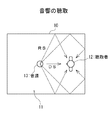
音像位置決定部32によって音像の位置が決定されると、駆動信号MDL,MDRによって直接音の支配率を調整できる。ここで、図11に示すように、聴取者12の左右側にスピーカ23L,23Rを設けるものとして、聴取者12の近くに音像を置きたい場合には、スピーカ23L,23Rを聴取者12側の向きとする。例えば、音像の位置を聴取者12の前方で近い位置Ibとするとき、図11のB方向付近に回転角を合わせて反射音の影響を少なくする。同様に、音像の位置を聴取者12の後方で近い位置Icとするとき、図11のC方向付近に回転角を合わせて反射音の影響を少なくする。反対に、聴取者からはなれた位置に音像を置きたい場合には、スピーカを外向きにする。例えば、音像の位置を聴取者12の前方で離れた位置Iaとするとき、図11のA方向付近に回転角を合わせて壁面10からの反射音の影響を大きくする。同様に、音像の位置を聴取者12の後方で離れた位置Idとするとき、図11のD方向付近に回転角を合わせて反射音の影響を大きくする。
【0040】
このように、音像の位置に応じてスピーカ23L,23Rを回転させて音響の出力方向を制御することで、例えばスピーカ23L,23RをA方向からD方向に回転させると、音像の位置が前方から後方に移動するものとなる。特に、聴取者12の左右側にスピーカ23L,23Rを設けることで、この音像の位置の移動が明確となり、臨場感の高い音響提示を行うことができる。また、スピーカ23L,23Rを回転することで、音響の出力方向を連続的に可変できるものであるから、音像の位置を連続的かつ滑らかに移動させることができる。
【0041】
また、音響信号処理部34で音響信号の信号レベルや位相を制御することで、音響の音圧や位相を容易かつ精度良く制御できるので、音像をより正しい位置に定位させて、さらに臨場感の高い音響提示を行うことができる。
【0042】
ここで、前後方向の音像の表現では、左右の音量差が無くなると共に左右の位相差が無くなるように調整音響信号SBL,SBRを生成する。左右方向の音像の表現では、左耳で聞こえた音と右耳で聞こえた音との音量差及び位相差によって音像の左右方向の位置が表現される。例えば図12の実線で示す右側の音響SURに対して、左側の音響SULを破線で示すように音量レベルを小さくすると共に、時間遅れTeを生じさせると、音源や音像の位置が中央より右側の位置に感じられる。このため、音像の位置に応じて、増幅係数α,βや位相補正値TDL,TDRの調整を行うことで、より臨場感が高い音響提示を行うことができる。
【0043】
位相補正値TDL,TDRの算出では、スピーカ23L,23Rの回転角度と時間差の関係を予め算出しておき、スピーカ23L,23Rの回転角度に応じた時間差に位相補正値TDL,TDRを加えることで、所望の位置に音像が形成されるように位相補正値TDL,TDRを調整する。
【0044】
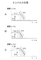
スピーカ23L,23Rの回転角度と時間差の関係は、図13に基づいて求めることができる。例えば、スピーカ23Lの角度を設定して、このスピーカ23Lから出力されたインパルス音に基づく聴取位置QLでのインパルス応答を測定する。図14Aはスピーカ23Lから出力されたインパルス音に基づくインパルス応答を示している。同様に、スピーカ23Rから出力されたインパルス音に基づくインパルス応答を測定する。図14Bはスピーカ23Rから出力されたインパルス音に基づくインパルス応答を示している。
【0045】
ここで、インパルス音の出力から最初の間接音が聴取位置に届くまでの時間TLO,TROを求める。なおインパルス応答は、直接測定しても良くシミュレーションで予め求めておくものとしても良い。
【0046】
このようにして時間TLO,TROを求めると、式(3)に基づいて時間差ΔTfを算出できる。すなわち、スピーカ23L,23Rの回転角度に基づく時間TLO,TROを用いて時間差ΔTfを求めることができる。なお、この時間差ΔTfは、聴取者に対して左右感覚を与える遅延量である。
ΔTf=TLO−TRO ・・・(3)
【0047】
このため、所望の位置に音像が形成するために必要とされる時間差ΔTgが時間差ΔTfで得ることができない場合、式(4)を満足するようにされるよう位相補正値TDを設定する。
ΔTg=ΔTf+TD ・・・(4)
【0048】
例えば、位相補正値TDRを設定したときには、図14Bに示すインパルス応答は、図14Cに示すものとなり、スピーカの回転だけでは表現できない音像の位置を、位相補正値を用いることで表示することができる。
【0049】
また、上述の音響信号処理部34では、音響信号SAL,SARの周波数帯域分離を行い、所望の周波数帯域の信号レベルが他の周波数帯域よりも高くなるように調整を行うものとする。この場合には、所望の周波数帯域の音響に基づく音像をより強調して表現できる。また、音響信号SAL,SARの周波数帯域分離を行い、周波数帯域に応じた信号処理を行うものとしても良い。例えば高音域や中音域に比べて低音域は音響の指向性が低く、どの方向から聞こえてくるかを認識しにくい。このため、中音域や高音域を強調するように信号処理を行うことで、音像を認識しやすくして臨場感の高い音響提示を行うことができる。
【0050】
ところで、上述のスピーカ23L,23Rでは、Z軸を中心として時計方向あるいは反時計方向に回転することで、音響の出力方向を制御するものとしたが、スピーカ23L,23Rの位置をY軸方向(前後方向)に移動することで、音響の出力方向を可変させるものとしても良い。
【0051】
図15は、スピーカ23L,23Rの位置をY軸方向に移動させる場合の構成を示している。例えば図15Aでは、スピーカ23L,23Rを回転させる際の回転半径rを大きくして、音響の出力方向を可変させるだけでなく、スピーカ23L,23Rの位置を前後方向に移動させる。あるいは、図15Bに示すように、回転駆動部を前後方向に移動させるスライド機構26を設けるものとして、スピーカ23L,23Rの回転と前後方向の移動を独立に行うものとする。ここで、例えばスピーカを前方向に移動させることで前方向に対する奥行き感を高めることができる。また、スピーカを後方向に移動させることで後方向に対する奥行き感を高めることができる。
【0052】
このように、音響提示制御装置30によって、音像を定位させる位置に応じて音響の出力方向や音圧及び位相のうち少なくとも一つを制御することで、臨場感の高い音響提示を行うことができる。
【0053】
さらに、上述の処理はハードウェアだけでなくソフトウェアで実現するものとしても良い。この場合の構成を図16に示す。コンピュータは、図16に示すようにCPU(Central Processing Unit)701を内蔵しており、このCPU701にはバス720を介してROM702,RAM703,ハード・ディスク・ドライブ704,入出力インタフェース705が接続されている。さらに、入出力インタフェース705には入力部711や記録媒体ドライブ712,通信部713,信号入力部714,信号出力部715が接続されている。
【0054】
外部装置から命令が入力されたり、キーボードやマウス等の操作手段あるいはマイク等の音声入力手段等を用いて構成された入力部711から命令が入力されたりると、この命令が入出力インタフェース705を介してCPU701に供給される。
【0055】
CPU701は、ROM702やRAM703あるいはハード・ディスク・ドライブ704に記憶されているプログラムを実行して、供給された命令に応じた処理を行う。さらに、ROM702やRAM703あるいはハード・ディスク・ドライブ704には、上述の音響提示システムにおける信号処理をコンピュータで実行させるための音響提示処理プログラムを予め記憶させて、信号入力部714に入力された信号に基づいて音響出力信号を生成して、信号出力部715から出力する。また、記録媒体に音響提示処理プログラムを記録しておくものとし、記録媒体ドライブ712によって、音響提示処理プログラムを記録媒体に記録しあるいは記録媒体に記録されている音響提示処理プログラムを再生してコンピュータで実行するものとしても良い。さらに、通信部713によって、音響提示処理プログラムを有線あるいは無線の伝送路を介して送信あるいは受信するものとし、受信した音響提示処理プログラムをコンピュータで実行するものとしても良い。
【0056】
次に、音響提示処理プログラムについて説明する。ここで、信号入力部714には、音響信号SAL,SARや位置情報信号PRに基づいて生成された情報信号WSが供給される場合を説明する。
【0057】
図17は音響取得処理を示すフローチャートである。この音響取得処理は、例えばビデオカメラ側あるいはコンピュータ側のいずれで行っても良い。
【0058】
ステップST1では、位置情報信号の生成を行う。すなわち、角度センサからの角度信号Spaや測距センサからの距離信号Spbに基づき極座標計算を行い、位置情報信号PRを生成する。また、この位置情報信号PRと音響信号SAL,SARを例えば多重化して情報信号WSを生成する。
【0059】
ステップST2では、生成した情報信号WSを記録媒体に記録あるいは外部機器に伝送するように設定されているか否かを判別する。ここで、情報信号の記録や伝送を行うように設定されている場合にはステップST3に進み、情報信号の記録や伝送を行わないように設定されている場合にはステップST4に進む。
【0060】
ステップST3では、情報信号の記録や伝送を行ってからステップST4に進む。ここで、情報信号を記録する場合には、情報信号を磁気や光等を利用して記録再生を行う記録媒体あるいは半導体等を用いて構成された記録媒体に記録する。また、情報信号を伝送する場合には、有線や無線の通信路を介して情報信号を出力する。
【0061】
ステップST4では、音響取得を終了するか否かを判別する。ここで、音響取得の終了操作が行われたときには音響取得処理を終了する。また、終了操作が行われていないときにはステップST1に戻り、情報信号の生成を継続する。
【0062】
図18は、音響提示処理を示すフローチャートである。ステップST11では供給された情報信号WSの分離を行う。例えば、記録媒体ドライブ712によって記録媒体に記録されている情報信号WSが再生されたとき、あるいは、通信部713を介して情報信号WSが供給されたとき、またはビデオカメラ等から情報信号WSが信号入力部714に供給されたとき、この情報信号WSから、音響信号SAL,SARと位置情報信号PRを分離してステップST12に進む。
【0063】
ステップST12では、音響の出力方向の決定を行い、位置情報信号PRによって示された音像の位置に応じたスピーカ23L,23Rの回転角を決定する。この回転角の決定では、音像の位置に対する回転角を、壁面10の設置状態等を考慮して予め求めてハード・ディスク装置やメモリに記憶ものとして、位置情報信号PRで示された音像の位置と対応する回転角を読み出すことで、回転角を容易に決定できる。
【0064】
ステップST13では、調整情報の生成を行い、音像の位置やスピーカの回転角等に基づいて、音響信号SAL,SARを調整するための係数や位相補正値を決定する。
【0065】
ステップST14では、ステップST12で決定された回転角となるようにスピーカ23L,23Rを回転させるための駆動信号MDL,MDRを生成して信号出力部715から出力させる。
【0066】
ステップST15では、ステップST13で生成された調整情報を用いて音響信号SAL,SARの調整を行い、調整音響信号SBL,SBRあるいは音響信号SOL,SORを生成して信号出力部715から出力させる。
【0067】
ステップST16では、音響信号の再生を終了するか否かを判別する。ここで、入力部711を用いて終了操作が行われたときには音響提示処理を終了する。また、終了操作が行われていないときにはステップST11に戻り、ステップST11からステップST15までの処理を繰り返す。
【0068】
このように処理することで、音像の位置に応じてスピーカ23L,23Rの回転や音響信号SAL,SARの調整が順次行われて、臨場感の高い奥行き感のある音響提示を行える。
【0069】
なお、上述の実施の形態では、スピーカの向きを変えて音響の出力方向を可変するものとしたが、音響出力方向が異なるように複数のスピーカを配置して音響出力手段を構成して、音響を出力するスピーカを切り替えることで音響の出力方向を可変するものとしても良い。例えば図19Aに示すように、球面上に複数のスピーカ27を設けるものとして、出力方向制御部33では、音響信号SOL,SORを供給するスピーカ27を切り替えることで音響の出力方向を全方向に渡って可変する。また、図19Bに示すように、円柱の側面に、周方向に複数のスピーカ27を設けるものとして、出力方向制御部33では、音響信号SOL,SORを供給するスピーカを切り替えることで音響の出力方向を全周に渡って可変する。このように、スピーカを切り替えることで音響の出力方向を可変すれば、スピーカを回転させる駆動機構やスピーカの回転機構が不要となり、可動部分のない構造が簡単な音響出力手段を構成できる。また、可動部分がないことから、音像の位置を速やかに移動させる場合でも容易に対応できる。
【0070】
また、音響出力手段は、スピーカを用いたものに限られるものではなく、音響を出力する発音体であれば良いことは勿論である。さらに、音響の出力方向が固定されているスピーカも合わせて用いるものとしても良い。例えば、固定されているスピーカから環境音や効果音等を出力すると共に、音響の出力方向が制御されるスピーカからは、移動する音源からの音響を出力すれば、さらに多彩な音響提示を行うことができる。
【0071】
【発明の効果】
この発明によれば、聴取者のほぼ真横の左右に、回転、回転半径方向に移動、又は前後方向に移動が可能として音響出力手段が設けられて、音像を定位させる位置に応じて、音響出力手段が回転、回転半径方向に移動、又は前後方向に移動されるので、臨場感や移動感及び奥行き感のある音響提示を行うことができる。
【0072】
また、音響の出力方向や音圧及び位相のうち少なくとも一つを制御するものとしたり、音響出力手段が壁面で仕切られた空間に設置された場合、壁面からの反射音を利用して音像が定位されて、臨場感や移動感及び奥行き感のある音響提示を行うことができる。
【0074】
さらに、所望の周波数帯域の音響レベルが他の周波数帯域よりも高くされるので、所望の周波数帯域の音響に基づく音像を強調することができる。また、音響の音圧や位相の制御は、音響信号の信号レベルや位相を制御することにより行われるので、音響の音圧や位相を簡単に制御できる。
【図面の簡単な説明】
【図1】音響の聴取を示す図である。
【図2】直接音と反射音の関係を示す図である。
【図3】音響提示システムの構成を示す図である。
【図4】スピーカの構成を示す図である。
【図5】聴取者と座標軸の関係を示す図である。
【図6】スピーカを回転させたときの直接音と反射音を示す図である。
【図7】音響提示制御装置の構成を示す図である。
【図8】位置検出部の構成を示す図である。
【図9】画像信号処理装置の構成を示す図である。
【図10】音響信号処理部の動作を説明するための図である。
【図11】音像の位置とスピーカの向きの関係を示す図である。
【図12】音像の左右方向の表現動作を説明するための図である。
【図13】回転角度と時間差の関係を説明するための図である。
【図14】インパルス応答を示す図である。
【図15】スピーカの他の構成を示す図である。
【図16】コンピュータを用いた場合の構成を示す図である。
【図17】音響取得処理を示すフローチャートである。
【図18】音響提示処理を示すフローチャートである。
【図19】音響出力手段の他の構成を示す図である。
【符号の説明】
11・・・空間、12・・・視聴者、13・・・音源、15・・・画像表示領域、23L,23R,27・・・スピーカ、24L,24R・・・回転駆動部、25L,25・・・支持体、26・・・スライド機構、30・・・音響提示制御装置、31・・・ユーザインタフェース部、32・・・音像位置決定部、33・・・出力方向制御部、34・・・音響信号処理部、35・・・信号増幅部、41・・・角度センサ、42・・・測距センサ、43・・・極座標算出部、50・・・画像信号処理部、51・・・シーンチェンジ検出部、52・・・動き検出部、53・・・画像位置移動部、704・・・ハード・ディスク・ドライブ、705・・・入出力インタフェース、711・・・入力部、712・・・記録媒体ドライブ、713・・・通信部、714・・・信号入力部、715・・・信号出力部[0001]
BACKGROUND OF THE INVENTION
The present invention relates to an acoustic presentation device and an acoustic presentation method. Specifically, the sound output means is rotated according to the position where the sound image based on the sound output from the sound output means is localized. as well as It is moved in the front-rear direction.
[0002]
[Prior art]
Conventionally, as a sound presentation method, not only the left and right channel speakers but also auxiliary speakers are fixedly arranged to enhance the depth and three-dimensional sound of the sound and provide a realistic sound presentation. ing. For example, in the 5.1 channel or 6.1 channel surround system used in movies, DVDs (Digital Versatile Disks), etc., an auxiliary speaker is provided in addition to the front to obtain a sense of depth more than stereo space, The sound presentation is enhanced by enhancing the sense of sound fusion.
[0003]
In addition, the impulse response of an arbitrary space is convolved with the sound collected in an anechoic room or the sound recorded on a compact disc, and the characteristics of the arbitrary room are reproduced. For example, the filter characteristics are set in advance so that the characteristics are the same as those of a reproduction space such as a concert hall, a live house, or a church, and the user selects a desired filter characteristic to reproduce the sound field of the desired reproduction space. Things are also done. Furthermore, virtual stereophonic sound that creates a three-dimensional sound field using left channel and right channel speakers is also realized.
[0004]
[Problems to be solved by the invention]
By the way, since such a sound presentation method uses a fixed speaker, the expression width of the sound is small. In addition, it is difficult to satisfactorily represent the depth in the front-rear direction in the vertical direction or in the middle position between the speakers.
[0005]
Therefore, in the present invention, it is possible to present sound with a sense of presence, a sense of movement, and a sense of depth. Acoustic presentation device and acoustic presentation method Is to provide.
[0006]
[Means for Solving the Problems]
The acoustic presentation device according to the present invention is provided on the left and right sides of the listener, as well as The sound output means that outputs sound that can be moved in the front-rear direction, and the sound output means is rotated according to the position where the sound image based on the sound output from the sound output means is localized. as well as It has an acoustic presentation control means for moving in the front-rear direction.
[0007]
The acoustic presentation method is Listening Rotate to the left and right almost right as well as Possible to move back and forth , Perform sound output based on the sound signal The sound output means is rotated according to the step of providing the sound output means and the position where the sound image based on the sound output from the sound output means is localized. as well as It has the process of moving to the front-back direction.
[0010]
In the present invention, sound output means for performing sound output is provided on the left and right sides of the listener, for example, in a space partitioned by wall surfaces. Depending on the position where the sound image based on the sound output from the sound output means is localized, the sound output means It is rotated, moved in the radial direction of rotation, or moved in the front-rear direction. Thus, the sound output direction is controlled, and the sound image is localized using the reflected sound from the wall surface.
[0011]
Further, at least one of the signal level and phase of the acoustic signal is adjusted according to the position where the sound image is localized, and the acoustic output means is driven based on the adjusted acoustic signal.
[0012]
DETAILED DESCRIPTION OF THE INVENTION
Hereinafter, an embodiment of the present invention will be described with reference to the drawings. FIG. 1 illustrates acoustic listening. When the
[0013]
FIG. 2 shows a model of the relationship between direct sound and reflected sound. When the distance L between the
[0014]
For this reason, in the present invention, by controlling at least one of the sound output direction, sound pressure, and phase according to the position where the sound image is localized, a sense of presence, a sense of movement, and a sense of depth in the front-rear direction and the up-down direction are obtained. Make an acoustic presentation. That is, if the sound output direction is varied, the direct sound DS and the reflected sound RS can be controlled by the reflection characteristics of the space where the sound is heard. Furthermore, it is possible to directly control the sound DS and the reflected sound RS by controlling the sound pressure and the phase, and it is possible to provide sound presentation with a sense of presence, a sense of movement, and a sense of depth.
[0015]
FIG. 3 shows the configuration of the sound presentation system. In this sound presentation system, a
[0016]
The
[0017]
When the sound is output from the
[0018]
Further, as shown in FIG. 6B, the
[0019]
FIG. 7 shows the configuration of the sound presentation control device. The
[0020]
The output
[0021]
The acoustic
[0022]
The
[0023]
The
[0024]
Next, the operation of the sound presentation control device will be described. When the
[0025]
In addition, for example, when the audio signal SAL, SAR is obtained by obtaining the sound in the shooting direction of the video camera by integrating the video camera and the microphone, the position detection unit is provided in the video camera. Generates a position information signal PR indicating the position of the sound source and supplies it to the sound image
[0026]
FIG. 8 shows the configuration of the position detection unit. The
[0027]
Here, when shooting is performed while chasing a desired subject with a video camera, sound from the desired subject is picked up by a microphone and acoustic signals SAL and SAR are generated. Further, the desired subject is set as the sound image position, and information indicating the direction and distance of the sound source is output as the position information signal PR.
[0028]
Furthermore, when the movement of the image is detected based on the image signal and the display position of the image is moved according to the detected movement, the display position of the moving subject is moved in accordance with the movement of the subject. The display position may be used as the position of the sound source, and a signal indicating the display position may be used as the position information signal PR.
[0029]
FIG. 9 shows a configuration of an image signal processing apparatus that generates an image output signal obtained by moving the display position of an image based on the image motion detection result and a signal indicating the display position.
[0030]
The image signal SV is supplied to the scene
[0031]
The scene
[0032]
The
[0033]
The image
[0034]
The sound image
[0035]
The output
[0036]
The acoustic
SBL (t) = α (θL) × SAL (t−TDL) (1)
SBR (t) = β (θR) × SBR (t−TDR) (2)
[0037]
In Expressions (1) and (2), “α (θL)” is an amplification coefficient based on the rotation angle θL, and “β (θR)” is an amplification coefficient based on the rotation angle θR. Furthermore, the phase correction values “TDL” and “TDR” represent time advance or time delay. The amplification coefficients “α (θL)”, “β (θR)”, and phase correction values “TDL” and “TDR” indicate the position of the sound image, the sound absorption coefficient and arrangement of the
[0038]
The adjusted acoustic signals SBL and SBR generated by the acoustic
[0039]
When the position of the sound image is determined by the sound image
[0040]
Thus, by rotating the
[0041]
In addition, since the sound signal pressure and phase of the sound can be controlled easily and accurately by controlling the signal level and phase of the sound signal by the sound
[0042]
Here, in the representation of the sound image in the front-rear direction, the adjusted acoustic signals SBL and SBR are generated so that the left-right volume difference is eliminated and the left-right phase difference is eliminated. In the representation of the sound image in the left-right direction, the position of the sound image in the left-right direction is represented by the volume difference and phase difference between the sound heard with the left ear and the sound heard with the right ear. For example, when the sound level on the right side SUR shown by the solid line in FIG. 12 is reduced as shown by the broken line on the left side sound SUL and the time delay Te is generated, the position of the sound source and the sound image is on the right side of the center. Felt in position. For this reason, sound adjustment with higher presence can be performed by adjusting the amplification coefficients α and β and the phase correction values TDL and TDR in accordance with the position of the sound image.
[0043]
In calculating the phase correction values TDL and TDR, the relationship between the rotation angle of the
[0044]
The relationship between the rotation angle of the
[0045]
Here, the time TLO, TRO from the output of the impulse sound until the first indirect sound reaches the listening position is obtained. The impulse response may be measured directly or may be obtained in advance by simulation.
[0046]
When the times TLO and TRO are obtained in this way, the time difference ΔTf can be calculated based on the equation (3). That is, the time difference ΔTf can be obtained using the times TLO and TRO based on the rotation angles of the
ΔTf = TLO-TRO (3)
[0047]
For this reason, when the time difference ΔTg required for forming a sound image at a desired position cannot be obtained by the time difference ΔTf, the phase correction value TD is set so as to satisfy Expression (4).
ΔTg = ΔTf + TD (4)
[0048]
For example, when the phase correction value TDR is set, the impulse response shown in FIG. 14B is as shown in FIG. 14C, and the position of the sound image that cannot be expressed only by the rotation of the speaker can be displayed by using the phase correction value. .
[0049]
The acoustic
[0050]
By the way, in the above-described
[0051]
FIG. 15 shows a configuration when the positions of the
[0052]
As described above, the sound
[0053]
Furthermore, the above-described processing may be realized not only by hardware but also by software. The configuration in this case is shown in FIG. The computer includes a CPU (Central Processing Unit) 701 as shown in FIG. 16, and a
[0054]
When a command is input from an external device, or when a command is input from an
[0055]
The
[0056]
Next, the sound presentation processing program will be described. Here, the case where the information signal WS generated based on the acoustic signals SAL and SAR and the position information signal PR is supplied to the
[0057]
FIG. 17 is a flowchart showing the sound acquisition process. This sound acquisition process may be performed on either the video camera side or the computer side, for example.
[0058]
In step ST1, a position information signal is generated. That is, polar coordinate calculation is performed based on the angle signal Spa from the angle sensor and the distance signal Spb from the distance measuring sensor to generate the position information signal PR. Further, the position information signal PR and the acoustic signals SAL and SAR are multiplexed, for example, to generate the information signal WS.
[0059]
In step ST2, it is determined whether or not the generated information signal WS is set to be recorded on a recording medium or transmitted to an external device. If it is set to record or transmit an information signal, the process proceeds to step ST3. If it is set not to record or transmit an information signal, the process proceeds to step ST4.
[0060]
In step ST3, the information signal is recorded and transmitted, and then the process proceeds to step ST4. Here, in the case of recording an information signal, the information signal is recorded on a recording medium that performs recording and reproduction using magnetism, light, or the like, or a recording medium configured using a semiconductor or the like. When transmitting an information signal, the information signal is output via a wired or wireless communication path.
[0061]
In step ST4, it is determined whether or not to end the sound acquisition. Here, when the sound acquisition end operation is performed, the sound acquisition process is ended. If the end operation has not been performed, the process returns to step ST1, and the generation of the information signal is continued.
[0062]
FIG. 18 is a flowchart showing the sound presentation process. In step ST11, the supplied information signal WS is separated. For example, when the information signal WS recorded on the recording medium is reproduced by the
[0063]
In step ST12, the sound output direction is determined, and the rotation angles of the
[0064]
In step ST13, adjustment information is generated, and coefficients and phase correction values for adjusting the acoustic signals SAL and SAR are determined based on the position of the sound image, the rotation angle of the speaker, and the like.
[0065]
In step ST14, drive signals MDL and MDR for rotating the
[0066]
In step ST15, the acoustic signals SAL and SAR are adjusted using the adjustment information generated in step ST13, and adjusted acoustic signals SBL and SBR or acoustic signals SOL and SOR are generated and output from the
[0067]
In step ST16, it is determined whether or not the reproduction of the acoustic signal is to be ended. Here, when a termination operation is performed using the
[0068]
By processing in this way, the rotation of the
[0069]
In the above embodiment, the direction of the speaker is changed to change the sound output direction. However, the sound output means is configured by arranging a plurality of speakers so that the sound output direction is different. It is good also as what changes the output direction of an acoustic by switching the speaker which outputs. For example, as shown in FIG. 19A, assuming that a plurality of
[0070]
Further, the sound output means is not limited to that using a speaker, and it is needless to say that it is a sounding body that outputs sound. Further, a speaker with a fixed sound output direction may also be used. For example, environmental sounds and sound effects can be output from a fixed speaker, and sound from a moving sound source can be output from a speaker whose sound output direction is controlled, so that various types of sound can be presented. Can do.
[0071]
【The invention's effect】
According to this invention, Sound output means is provided on the left and right sides of the listener almost right and left, allowing rotation, moving in the radial direction of rotation, or moving in the front-rear direction. Depending on the position where the sound image is localized, The sound output means is rotated, moved in the radial direction of rotation, or moved in the front-rear direction. Therefore, it is possible to present sound with a sense of presence, a sense of movement, and a sense of depth.
[0072]
In addition, it shall control at least one of the sound output direction, sound pressure and phase, or the sound output means in a space partitioned by walls. When installed The sound image is localized using the reflected sound from the wall surface, and sound presentation with a sense of presence, a sense of movement, and a sense of depth can be performed.
[0074]
Furthermore, since the sound level of the desired frequency band is made higher than the other frequency bands, the sound image based on the sound of the desired frequency band can be emphasized. Moreover, since the sound pressure and phase of the sound are controlled by controlling the signal level and phase of the sound signal, the sound pressure and phase of the sound can be easily controlled.
[Brief description of the drawings]
FIG. 1 is a diagram illustrating listening to sound.
FIG. 2 is a diagram showing the relationship between direct sound and reflected sound.
FIG. 3 is a diagram illustrating a configuration of an audio presentation system.
FIG. 4 is a diagram illustrating a configuration of a speaker.
FIG. 5 is a diagram showing a relationship between a listener and coordinate axes.
FIG. 6 is a diagram illustrating a direct sound and a reflected sound when a speaker is rotated.
FIG. 7 is a diagram illustrating a configuration of an audio presentation control apparatus.
FIG. 8 is a diagram illustrating a configuration of a position detection unit.
FIG. 9 is a diagram illustrating a configuration of an image signal processing apparatus.
FIG. 10 is a diagram for explaining the operation of an acoustic signal processing unit.
FIG. 11 is a diagram illustrating the relationship between the position of a sound image and the direction of a speaker.
FIG. 12 is a diagram for explaining the operation of expressing a sound image in the left-right direction.
FIG. 13 is a diagram for explaining a relationship between a rotation angle and a time difference.
FIG. 14 is a diagram showing an impulse response.
FIG. 15 is a diagram illustrating another configuration of a speaker.
FIG. 16 is a diagram illustrating a configuration when a computer is used.
FIG. 17 is a flowchart showing sound acquisition processing.
FIG. 18 is a flowchart showing sound presentation processing.
FIG. 19 is a diagram showing another configuration of sound output means.
[Explanation of symbols]
DESCRIPTION OF
Claims (4)
前記音響出力手段から出力された音響に基づく音像を定位させる位置に応じて、前記音響出力手段を回転及び前後方向に移動させる音響提示制御手段とを有する
音響提示装置。A sound output means that is provided on the left and right sides of the listener and that outputs sound that can be rotated and moved in the front-rear direction;
Depending on the location to localize a sound image based on sound output from the sound output means, that having a acoustic presentation control means for moving said sound output means in the rotational and longitudinal direction
Acoustic presentation device.
請求項1記載の音響提示装置。Said sound presentation control means that controls at least one of the acoustic sound pressure and phase
Acoustic presentation device of 請 Motomeko 1, wherein the.
請求項2記載の音響提示装置。 The sound presentation control means makes the sound level of a desired frequency band higher than other frequency bands.
The sound presentation apparatus according to claim 2 .
前記音響出力手段から出力された音響に基づく音像を定位させる位置に応じて、前記音響出力手段を回転及び前後方向に移動させる工程を有するA step of rotating and moving the sound output means in the front-rear direction according to a position where a sound image based on sound output from the sound output means is localized.
音響提示方法。Sound presentation method.
Priority Applications (1)
| Application Number | Priority Date | Filing Date | Title |
|---|---|---|---|
| JP2002151466A JP4363004B2 (en) | 2002-05-24 | 2002-05-24 | Acoustic presentation device and acoustic presentation method |
Applications Claiming Priority (1)
| Application Number | Priority Date | Filing Date | Title |
|---|---|---|---|
| JP2002151466A JP4363004B2 (en) | 2002-05-24 | 2002-05-24 | Acoustic presentation device and acoustic presentation method |
Publications (3)
| Publication Number | Publication Date |
|---|---|
| JP2003348698A JP2003348698A (en) | 2003-12-05 |
| JP2003348698A5 JP2003348698A5 (en) | 2005-10-06 |
| JP4363004B2 true JP4363004B2 (en) | 2009-11-11 |
Family
ID=29769054
Family Applications (1)
| Application Number | Title | Priority Date | Filing Date |
|---|---|---|---|
| JP2002151466A Expired - Fee Related JP4363004B2 (en) | 2002-05-24 | 2002-05-24 | Acoustic presentation device and acoustic presentation method |
Country Status (1)
| Country | Link |
|---|---|
| JP (1) | JP4363004B2 (en) |
Cited By (1)
| Publication number | Priority date | Publication date | Assignee | Title |
|---|---|---|---|---|
| US8196386B2 (en) | 2008-03-19 | 2012-06-12 | Honeywell International Inc. | Position sensors, metering valve assemblies, and fuel delivery and control systems |
Families Citing this family (5)
| Publication number | Priority date | Publication date | Assignee | Title |
|---|---|---|---|---|
| JP5181564B2 (en) * | 2007-07-31 | 2013-04-10 | ヤマハ株式会社 | Audio playback device |
| JP6289121B2 (en) * | 2014-01-23 | 2018-03-07 | キヤノン株式会社 | Acoustic signal processing device, moving image photographing device, and control method thereof |
| HK1195445A2 (en) * | 2014-05-08 | 2014-11-07 | 黃偉明 | Endpoint mixing system and reproduction method of endpoint mixed sounds |
| CN108347669B (en) * | 2018-04-18 | 2024-04-05 | 深圳市健马科技发展有限公司 | Angle-adjustable sound box structure, sound system and adjusting method |
| JP7013513B2 (en) * | 2020-03-31 | 2022-01-31 | 本田技研工業株式会社 | vehicle |
-
2002
- 2002-05-24 JP JP2002151466A patent/JP4363004B2/en not_active Expired - Fee Related
Cited By (1)
| Publication number | Priority date | Publication date | Assignee | Title |
|---|---|---|---|---|
| US8196386B2 (en) | 2008-03-19 | 2012-06-12 | Honeywell International Inc. | Position sensors, metering valve assemblies, and fuel delivery and control systems |
Also Published As
| Publication number | Publication date |
|---|---|
| JP2003348698A (en) | 2003-12-05 |
Similar Documents
| Publication | Publication Date | Title |
|---|---|---|
| JP7229925B2 (en) | Gain control in spatial audio systems | |
| JP6117384B2 (en) | Adjusting the beam pattern of the speaker array based on the location of one or more listeners | |
| JP4914124B2 (en) | Sound image control apparatus and sound image control method | |
| JP2964514B2 (en) | Sound signal reproduction device | |
| JP4819823B2 (en) | Acoustic system driving apparatus, driving method, and acoustic system | |
| US8170246B2 (en) | Apparatus and method for reproducing surround wave field using wave field synthesis | |
| JP5992409B2 (en) | System and method for sound reproduction | |
| JP2007266967A (en) | Sound image localizer and multichannel audio reproduction device | |
| WO1991011079A1 (en) | Apparatus for reproducing acoustic signals | |
| CA2401986A1 (en) | System and method for optimization of three-dimensional audio | |
| JP2013514696A (en) | Apparatus and method for converting a first parametric spatial audio signal to a second parametric spatial audio signal | |
| US11122381B2 (en) | Spatial audio signal processing | |
| CN109891503A (en) | Acoustics scene back method and device | |
| JPWO2018060549A5 (en) | ||
| CN112672251A (en) | Control method and system of loudspeaker, storage medium and loudspeaker | |
| JP4363004B2 (en) | Acoustic presentation device and acoustic presentation method | |
| JP2671329B2 (en) | Audio player | |
| JP3968882B2 (en) | Speaker integrated karaoke apparatus and speaker integrated apparatus | |
| JP5505763B2 (en) | Sound field creation device | |
| JP2900985B2 (en) | Headphone playback device | |
| JPH0993690A (en) | Speaker unit | |
| JP2893779B2 (en) | Headphone equipment | |
| JP2005318396A (en) | Audio regenerating system with acoustic field correcting function | |
| JP2012253707A (en) | Stereoscopic video display device and sound reproduction device | |
| JPH11187499A (en) | Sound field control method |
Legal Events
| Date | Code | Title | Description |
|---|---|---|---|
| A521 | Written amendment |
Free format text: JAPANESE INTERMEDIATE CODE: A523 Effective date: 20050520 |
|
| A621 | Written request for application examination |
Free format text: JAPANESE INTERMEDIATE CODE: A621 Effective date: 20050520 |
|
| RD04 | Notification of resignation of power of attorney |
Free format text: JAPANESE INTERMEDIATE CODE: A7424 Effective date: 20060426 |
|
| A131 | Notification of reasons for refusal |
Free format text: JAPANESE INTERMEDIATE CODE: A131 Effective date: 20070605 |
|
| A521 | Written amendment |
Free format text: JAPANESE INTERMEDIATE CODE: A523 Effective date: 20070806 |
|
| A131 | Notification of reasons for refusal |
Free format text: JAPANESE INTERMEDIATE CODE: A131 Effective date: 20081216 |
|
| A521 | Written amendment |
Free format text: JAPANESE INTERMEDIATE CODE: A523 Effective date: 20090216 |
|
| A02 | Decision of refusal |
Free format text: JAPANESE INTERMEDIATE CODE: A02 Effective date: 20090317 |
|
| A521 | Written amendment |
Free format text: JAPANESE INTERMEDIATE CODE: A523 Effective date: 20090518 |
|
| A911 | Transfer of reconsideration by examiner before appeal (zenchi) |
Free format text: JAPANESE INTERMEDIATE CODE: A911 Effective date: 20090528 |
|
| TRDD | Decision of grant or rejection written | ||
| A01 | Written decision to grant a patent or to grant a registration (utility model) |
Free format text: JAPANESE INTERMEDIATE CODE: A01 Effective date: 20090728 |
|
| A01 | Written decision to grant a patent or to grant a registration (utility model) |
Free format text: JAPANESE INTERMEDIATE CODE: A01 |
|
| A61 | First payment of annual fees (during grant procedure) |
Free format text: JAPANESE INTERMEDIATE CODE: A61 Effective date: 20090810 |
|
| FPAY | Renewal fee payment (event date is renewal date of database) |
Free format text: PAYMENT UNTIL: 20120828 Year of fee payment: 3 |
|
| FPAY | Renewal fee payment (event date is renewal date of database) |
Free format text: PAYMENT UNTIL: 20120828 Year of fee payment: 3 |
|
| FPAY | Renewal fee payment (event date is renewal date of database) |
Free format text: PAYMENT UNTIL: 20130828 Year of fee payment: 4 |
|
| R250 | Receipt of annual fees |
Free format text: JAPANESE INTERMEDIATE CODE: R250 |
|
| R250 | Receipt of annual fees |
Free format text: JAPANESE INTERMEDIATE CODE: R250 |
|
| LAPS | Cancellation because of no payment of annual fees |