JP4362063B2 - Control system for power converter and method for controlling operation of power converter - Google Patents
Control system for power converter and method for controlling operation of power converter Download PDFInfo
- Publication number
- JP4362063B2 JP4362063B2 JP2003516146A JP2003516146A JP4362063B2 JP 4362063 B2 JP4362063 B2 JP 4362063B2 JP 2003516146 A JP2003516146 A JP 2003516146A JP 2003516146 A JP2003516146 A JP 2003516146A JP 4362063 B2 JP4362063 B2 JP 4362063B2
- Authority
- JP
- Japan
- Prior art keywords
- power
- current
- signal
- voltage
- control
- Prior art date
- Legal status (The legal status is an assumption and is not a legal conclusion. Google has not performed a legal analysis and makes no representation as to the accuracy of the status listed.)
- Expired - Fee Related
Links
Images


Classifications
-
- H—ELECTRICITY
- H02—GENERATION; CONVERSION OR DISTRIBUTION OF ELECTRIC POWER
- H02J—CIRCUIT ARRANGEMENTS OR SYSTEMS FOR SUPPLYING OR DISTRIBUTING ELECTRIC POWER; SYSTEMS FOR STORING ELECTRIC ENERGY
- H02J3/00—Circuit arrangements for ac mains or ac distribution networks
- H02J3/18—Arrangements for adjusting, eliminating or compensating reactive power in networks
-
- H—ELECTRICITY
- H02—GENERATION; CONVERSION OR DISTRIBUTION OF ELECTRIC POWER
- H02J—CIRCUIT ARRANGEMENTS OR SYSTEMS FOR SUPPLYING OR DISTRIBUTING ELECTRIC POWER; SYSTEMS FOR STORING ELECTRIC ENERGY
- H02J3/00—Circuit arrangements for ac mains or ac distribution networks
- H02J3/38—Arrangements for parallely feeding a single network by two or more generators, converters or transformers
- H02J3/381—Dispersed generators
-
- H—ELECTRICITY
- H02—GENERATION; CONVERSION OR DISTRIBUTION OF ELECTRIC POWER
- H02M—APPARATUS FOR CONVERSION BETWEEN AC AND AC, BETWEEN AC AND DC, OR BETWEEN DC AND DC, AND FOR USE WITH MAINS OR SIMILAR POWER SUPPLY SYSTEMS; CONVERSION OF DC OR AC INPUT POWER INTO SURGE OUTPUT POWER; CONTROL OR REGULATION THEREOF
- H02M7/00—Conversion of ac power input into dc power output; Conversion of dc power input into ac power output
- H02M7/02—Conversion of ac power input into dc power output without possibility of reversal
- H02M7/40—Conversion of ac power input into dc power output without possibility of reversal by combination of static with dynamic converters; by combination of dynamo-electric with other dynamic or static converters
-
- H—ELECTRICITY
- H02—GENERATION; CONVERSION OR DISTRIBUTION OF ELECTRIC POWER
- H02J—CIRCUIT ARRANGEMENTS OR SYSTEMS FOR SUPPLYING OR DISTRIBUTING ELECTRIC POWER; SYSTEMS FOR STORING ELECTRIC ENERGY
- H02J2300/00—Systems for supplying or distributing electric power characterised by decentralized, dispersed, or local generation
- H02J2300/20—The dispersed energy generation being of renewable origin
- H02J2300/22—The renewable source being solar energy
- H02J2300/24—The renewable source being solar energy of photovoltaic origin
-
- H—ELECTRICITY
- H02—GENERATION; CONVERSION OR DISTRIBUTION OF ELECTRIC POWER
- H02J—CIRCUIT ARRANGEMENTS OR SYSTEMS FOR SUPPLYING OR DISTRIBUTING ELECTRIC POWER; SYSTEMS FOR STORING ELECTRIC ENERGY
- H02J2300/00—Systems for supplying or distributing electric power characterised by decentralized, dispersed, or local generation
- H02J2300/30—The power source being a fuel cell
-
- H—ELECTRICITY
- H02—GENERATION; CONVERSION OR DISTRIBUTION OF ELECTRIC POWER
- H02J—CIRCUIT ARRANGEMENTS OR SYSTEMS FOR SUPPLYING OR DISTRIBUTING ELECTRIC POWER; SYSTEMS FOR STORING ELECTRIC ENERGY
- H02J9/00—Circuit arrangements for emergency or stand-by power supply, e.g. for emergency lighting
- H02J9/04—Circuit arrangements for emergency or stand-by power supply, e.g. for emergency lighting in which the distribution system is disconnected from the normal source and connected to a standby source
- H02J9/06—Circuit arrangements for emergency or stand-by power supply, e.g. for emergency lighting in which the distribution system is disconnected from the normal source and connected to a standby source with automatic change-over, e.g. UPS systems
- H02J9/062—Circuit arrangements for emergency or stand-by power supply, e.g. for emergency lighting in which the distribution system is disconnected from the normal source and connected to a standby source with automatic change-over, e.g. UPS systems for AC powered loads
-
- H—ELECTRICITY
- H02—GENERATION; CONVERSION OR DISTRIBUTION OF ELECTRIC POWER
- H02M—APPARATUS FOR CONVERSION BETWEEN AC AND AC, BETWEEN AC AND DC, OR BETWEEN DC AND DC, AND FOR USE WITH MAINS OR SIMILAR POWER SUPPLY SYSTEMS; CONVERSION OF DC OR AC INPUT POWER INTO SURGE OUTPUT POWER; CONTROL OR REGULATION THEREOF
- H02M1/00—Details of apparatus for conversion
- H02M1/0003—Details of control, feedback or regulation circuits
- H02M1/0025—Arrangements for modifying reference values, feedback values or error values in the control loop of a converter
-
- Y—GENERAL TAGGING OF NEW TECHNOLOGICAL DEVELOPMENTS; GENERAL TAGGING OF CROSS-SECTIONAL TECHNOLOGIES SPANNING OVER SEVERAL SECTIONS OF THE IPC; TECHNICAL SUBJECTS COVERED BY FORMER USPC CROSS-REFERENCE ART COLLECTIONS [XRACs] AND DIGESTS
- Y02—TECHNOLOGIES OR APPLICATIONS FOR MITIGATION OR ADAPTATION AGAINST CLIMATE CHANGE
- Y02B—CLIMATE CHANGE MITIGATION TECHNOLOGIES RELATED TO BUILDINGS, e.g. HOUSING, HOUSE APPLIANCES OR RELATED END-USER APPLICATIONS
- Y02B10/00—Integration of renewable energy sources in buildings
- Y02B10/70—Hybrid systems, e.g. uninterruptible or back-up power supplies integrating renewable energies
-
- Y—GENERAL TAGGING OF NEW TECHNOLOGICAL DEVELOPMENTS; GENERAL TAGGING OF CROSS-SECTIONAL TECHNOLOGIES SPANNING OVER SEVERAL SECTIONS OF THE IPC; TECHNICAL SUBJECTS COVERED BY FORMER USPC CROSS-REFERENCE ART COLLECTIONS [XRACs] AND DIGESTS
- Y02—TECHNOLOGIES OR APPLICATIONS FOR MITIGATION OR ADAPTATION AGAINST CLIMATE CHANGE
- Y02B—CLIMATE CHANGE MITIGATION TECHNOLOGIES RELATED TO BUILDINGS, e.g. HOUSING, HOUSE APPLIANCES OR RELATED END-USER APPLICATIONS
- Y02B90/00—Enabling technologies or technologies with a potential or indirect contribution to GHG emissions mitigation
- Y02B90/10—Applications of fuel cells in buildings
-
- Y—GENERAL TAGGING OF NEW TECHNOLOGICAL DEVELOPMENTS; GENERAL TAGGING OF CROSS-SECTIONAL TECHNOLOGIES SPANNING OVER SEVERAL SECTIONS OF THE IPC; TECHNICAL SUBJECTS COVERED BY FORMER USPC CROSS-REFERENCE ART COLLECTIONS [XRACs] AND DIGESTS
- Y02—TECHNOLOGIES OR APPLICATIONS FOR MITIGATION OR ADAPTATION AGAINST CLIMATE CHANGE
- Y02E—REDUCTION OF GREENHOUSE GAS [GHG] EMISSIONS, RELATED TO ENERGY GENERATION, TRANSMISSION OR DISTRIBUTION
- Y02E10/00—Energy generation through renewable energy sources
- Y02E10/50—Photovoltaic [PV] energy
- Y02E10/56—Power conversion systems, e.g. maximum power point trackers
-
- Y—GENERAL TAGGING OF NEW TECHNOLOGICAL DEVELOPMENTS; GENERAL TAGGING OF CROSS-SECTIONAL TECHNOLOGIES SPANNING OVER SEVERAL SECTIONS OF THE IPC; TECHNICAL SUBJECTS COVERED BY FORMER USPC CROSS-REFERENCE ART COLLECTIONS [XRACs] AND DIGESTS
- Y02—TECHNOLOGIES OR APPLICATIONS FOR MITIGATION OR ADAPTATION AGAINST CLIMATE CHANGE
- Y02E—REDUCTION OF GREENHOUSE GAS [GHG] EMISSIONS, RELATED TO ENERGY GENERATION, TRANSMISSION OR DISTRIBUTION
- Y02E10/00—Energy generation through renewable energy sources
- Y02E10/70—Wind energy
- Y02E10/76—Power conversion electric or electronic aspects
-
- Y—GENERAL TAGGING OF NEW TECHNOLOGICAL DEVELOPMENTS; GENERAL TAGGING OF CROSS-SECTIONAL TECHNOLOGIES SPANNING OVER SEVERAL SECTIONS OF THE IPC; TECHNICAL SUBJECTS COVERED BY FORMER USPC CROSS-REFERENCE ART COLLECTIONS [XRACs] AND DIGESTS
- Y02—TECHNOLOGIES OR APPLICATIONS FOR MITIGATION OR ADAPTATION AGAINST CLIMATE CHANGE
- Y02E—REDUCTION OF GREENHOUSE GAS [GHG] EMISSIONS, RELATED TO ENERGY GENERATION, TRANSMISSION OR DISTRIBUTION
- Y02E40/00—Technologies for an efficient electrical power generation, transmission or distribution
- Y02E40/30—Reactive power compensation
-
- Y—GENERAL TAGGING OF NEW TECHNOLOGICAL DEVELOPMENTS; GENERAL TAGGING OF CROSS-SECTIONAL TECHNOLOGIES SPANNING OVER SEVERAL SECTIONS OF THE IPC; TECHNICAL SUBJECTS COVERED BY FORMER USPC CROSS-REFERENCE ART COLLECTIONS [XRACs] AND DIGESTS
- Y02—TECHNOLOGIES OR APPLICATIONS FOR MITIGATION OR ADAPTATION AGAINST CLIMATE CHANGE
- Y02P—CLIMATE CHANGE MITIGATION TECHNOLOGIES IN THE PRODUCTION OR PROCESSING OF GOODS
- Y02P90/00—Enabling technologies with a potential contribution to greenhouse gas [GHG] emissions mitigation
- Y02P90/40—Fuel cell technologies in production processes
Abstract
Description
先の出願の情報
[0001] 本出願は、3001年7月23日出願の仮出願番号第60/307,658号の特典を主張する。
Information on Previous Application [0001] This application claims the benefit of
発明の背景
[0002] 世界中で開発中の多くのタイプの新しい分散型発電(DG)及びエネルギ蓄積に関する製品がある。これらには、燃料電池、フライホイール、先端技術の電池、マイクロタービン、スターリング・エンジン、風力タービン、太陽電池、及び2重層コンデンサが含まれる。これらの機器はそれぞれ、その出力端に、有用な交流(AC)電力を作り出すための電子式電力インバータを必要とする。一般に、この電力は、50又は60Hzの単相又は3相電力である。
BACKGROUND OF THE INVENTION [0002] There are many types of new distributed generation (DG) and energy storage products in development around the world. These include fuel cells, flywheels, advanced technology cells, micro turbines, Stirling engines, wind turbines, solar cells, and double layer capacitors. Each of these devices requires an electronic power inverter at its output to produce useful alternating current (AC) power. Generally, this power is 50 or 60 Hz single phase or three phase power.
[0003] これらの機器を互いにかつユーティリティ・グリッドに接続するための数多くの技術が特許及び文献に記載されている。これらすべての技術では、並列の電力コンバータの使用を含む。こうしたコンバータは2種類に分類される。即ち、コンバータの直流(DC)側で機器を並列にされるデバイス、またはコンバータのAC側で並列にされるデバイスである。 [0003] Numerous techniques for connecting these devices to each other and to the utility grid have been described in patents and literature. All these technologies involve the use of parallel power converters. These converters are classified into two types. That is, a device in which equipment is paralleled on the direct current (DC) side of the converter or a device in parallel on the AC side of the converter.
[0004] DC側で機器を並列に接続する考え方では、1台の大型インバータを使用することができ、それによってインバータ(逆変換装置)のコストが下がる。今日では、DC側で機器を並列にする動機付けは以前ほど大きくない。なぜなら、複数のインバータ・システム用の制御装置のコストが大きく下がったからである。大きいシステムの場合、DC側の技術では、DC配電システムを使用する。この場合、それぞれの分散型発電機はDC配電システムへDC電力を供給し、それぞれの負荷はそれ自体のインバータを有する。このシステムでは、1つのインバータが故障すると、負荷の損失が生じることになる。 [0004] In the idea of connecting devices in parallel on the DC side, one large inverter can be used, thereby reducing the cost of the inverter (inverse converter). Today, the motivation to parallel equipment on the DC side is not as great as before. This is because the cost of a control device for a plurality of inverter systems has greatly decreased. For large systems, the DC side technology uses a DC power distribution system. In this case, each distributed generator supplies DC power to the DC power distribution system, and each load has its own inverter. In this system, if one inverter fails, load loss occurs.
[0005] AC側で機器を並列にすると、負荷が交流なので、本来、信頼性がより高くなる。1つの機器が故障しても、いくらかの余分な能力がある限り、負荷へのAC電力を落とす必要はない。 [0005] When devices are arranged in parallel on the AC side, since the load is an alternating current, the reliability is inherently higher. If one device fails, there is no need to reduce AC power to the load as long as there is some extra capacity.
[0006] 複数の電力用電子ユニットを並列に接続するのに用いる典型的な方法は、1つをマスタにし、残りをスレーブにすることである。電圧源がマスタであり、電流源がスレーブである。この方法は、負荷が線形的であり、急激なサージがなく、有電力のみを引き出す場合には、うまく機能する。これらすべての特徴が揃っていないと、問題が生じ得る。これらの問題は、並列に接続されたインバータ間で高帯域制御システムを使用することによって、ある程度は克服することができる。しかし、一般に、これらの制御システムは、大規模又は分散したシステムには適用可能ではない。更に、並列に接続されたインバータ間で高速の通信が必要とされるので、並列冗長電力システムでは一点故障問題が生じることになり、従って、マスタ・スレーブ方式の信頼性が低くなる。 [0006] A typical method used to connect multiple power electronics units in parallel is to make one the master and the rest slaves. The voltage source is a master and the current source is a slave. This method works well when the load is linear, there is no sudden surge, and only the power is drawn. If all these features are not in place, problems can arise. These problems can be overcome to some extent by using a high bandwidth control system between the inverters connected in parallel. However, in general, these control systems are not applicable to large or distributed systems. Furthermore, since high-speed communication is required between the inverters connected in parallel, a one-point failure problem occurs in the parallel redundant power system, and therefore the reliability of the master / slave system is lowered.
[0007] AC電力システムにおいて並列接続インバータ間で、インバータに接続された制御回路を使用せずに、負荷を分担するための機器が開発されてきた。このようなシステムの例が、タシティノ・ジュニア(Tassitino,Jr)他の米国特許第5,745,356号、及びワラース(Wallace)他の第6,118,680号に記載されている。負荷の分担に必要な情報は、これらのシステムの各インバータの出力から得られる。各インバータの出力は、この情報に基づいて調整され、それによって、システムのすべてのインバータが等しく負荷を分担する。しかし残念ながら、これらのシステムでは、電流の高調波及び過渡状態が分担されるとは考えられず、また、明らかに無効電流も分担されない。 [0007] In an AC power system, devices for sharing a load have been developed between parallel-connected inverters without using a control circuit connected to the inverter. Examples of such systems are described in US Pat. No. 5,745,356 to Tassino, Jr et al. And 6,118,680 to Wallace et al. Information necessary for load sharing is obtained from the output of each inverter in these systems. The output of each inverter is adjusted based on this information, so that all inverters in the system share the load equally. Unfortunately, however, these systems do not seem to share current harmonics and transients, and clearly do not share reactive current.
発明の概要
[0008] 本発明の一態様は、エネルギ入力としてDC電力を受け取り、AC電力網へ送出するためのAC電力出力を提供する制御電流源のための制御システムであり、このAC電力出力は出力電圧を有するものである。この制御システムは、制御電流源に接続可能な電圧信号デバイスを備え、電圧信号デバイスは、制御電流源を制御する入力としての、AC電力出力の電圧を表す電圧フィードバック信号を提供する。更に、この制御システムは、制御電流源からのAC電力出力の特性の関数として制御用の電流信号を生成する電流調整器を備える。以下、この制御用の電流信号をインピーダンス電流信号といい、この電流調整器をインピーダンス電流調整器という。
SUMMARY OF THE INVENTION [0008] One aspect of the present invention is a control system for a controlled current source that receives DC power as an energy input and provides an AC power output for delivery to an AC power network, the AC power output being It has an output voltage. The control system comprises a voltage signal device connectable to a control current source, the voltage signal device providing a voltage feedback signal representing the voltage of the AC power output as an input to control the control current source. In addition, the control system includes a to that current regulator generates a current signal of the control as a function of the characteristics of the AC power output from the controlled current source. Hereinafter, this control current signal is referred to as an impedance current signal, and this current regulator is referred to as an impedance current regulator.
[0009] 本発明の別の態様は、AC電力網へAC電力を供給するシステムである。このシステムは、基準AC電圧信号を提供する第1供給源と、実電流コマンド信号を提供する第2供給源と、無効電流コマンド信号を提供する第3供給源と共に使用するためのものである。このシステムは、DC電力源と、DC電力を、出力電圧を有するAC電力に変換するコンバータとを有する制御電流源を含む。このシステムは、合成電流コマンド信号を生成する電流コマンド・ユニットも含む。この電流コマンド・ユニットは、制御電流源に接続され、第1及び第2供給源に接続可能である。この電流コマンド・ユニットは、インピーダンス電流信号を提供するインピーダンス電流調整器と、インピーダンス電流を、第2供給源からの実電流コマンド信号へ及び第3供給源からの無効電流コマンド信号へ加えて、合成電流コマンド信号を生成する加算ユニットとを含む。 [0009] Another aspect of the invention is a system for supplying AC power to an AC power network. The system is for use with a first source that provides a reference AC voltage signal, a second source that provides an actual current command signal, and a third source that provides a reactive current command signal. The system includes a controlled current source having a DC power source and a converter that converts the DC power to AC power having an output voltage. The system also includes a current command unit that generates a composite current command signal. The current command unit is connected to a control current source and can be connected to first and second sources. The current command unit includes an impedance current regulator that provides an impedance current signal, and adds the impedance current to the actual current command signal from the second source and to the reactive current command signal from the third source to synthesize And a summing unit for generating a current command signal.
[0010] 本発明の別の態様は、AC電力網に接続され、AC電力出力を供給する電力コンバータの動作を制御する方法である。この方法は、1つのステップとして、電力コンバータからの出力電圧を表す基準AC電圧信号を提供することを含む。次いで、制御用の電流コマンド信号(以下、インピーダンス電流コマンド信号)が生成されるが、ここで、このインピーダンス電流コマンド信号は、基準AC電圧信号に基づいて生成されるものである。次に、このインピーダンス電流コマンド信号に基づいて電力コンバータの動作を制御する電圧コマンド信号が生成され、この電圧コマンド信号が電力コンバータへ供給される。 [0010] Another aspect of the invention is a method for controlling the operation of a power converter connected to an AC power network and providing an AC power output. The method includes providing a reference AC voltage signal representative of the output voltage from the power converter as one step. Next, a current command signal for control (hereinafter, impedance current command signal ) is generated. Here, the impedance current command signal is generated based on the reference AC voltage signal. Next, a voltage command signal for controlling the operation of the power converter is generated based on the impedance current command signal, and the voltage command signal is supplied to the power converter.
[0011] 本発明の別の態様は、分散型の電力生成網である。この生成網は、AC電力を供給するAC電力網と、DC電力を供給するDC電力源とを備える。更に、この生成網は、DC電力をAC電力に変換する電力コンバータを含む。この電力コンバータは、AC電力網及びDC電力源に接続される。この生成網は、電力コンバータに接続された制御システムを更に含み、この制御システムは、電力コンバータの動作を制御する電圧コマンド信号を供給する。この制御システムは、(i)前記DC電力源によって提供される前記AC電力の電圧を表す電圧フィードバック信号と、(ii)前記DC電力源によって提供されるAC電力の関数としてのインピーダンス電流信号とを生成する。更に、この制御システムは、電圧フィードバック信号及びインピーダンス電流信号に基づいて電圧コマンド信号を生成する。 [0011] Another aspect of the present invention is a distributed power generation network. The generation network includes an AC power network that supplies AC power and a DC power source that supplies DC power. In addition, the generation network includes a power converter that converts DC power to AC power. The power converter is connected to an AC power network and a DC power source. The generator network further includes a control system connected to the power converter, which provides a voltage command signal that controls the operation of the power converter. The control system includes (i) a voltage feedback signal representative of the voltage of the AC power provided by the DC power source, and (ii) an impedance current signal as a function of the AC power provided by the DC power source. Generate. In addition, the control system generates a voltage command signal based on the voltage feedback signal and the impedance current signal.
[0012] 本発明を説明するために、現時点で好ましい本発明の形態を図面に示す。ただし、本発明は、図面に示すそのままの構成及び手段に限定されないことを理解されたい。 [0012] For the purpose of illustrating the invention, there are shown in the drawings forms of the invention that are presently preferred. However, it should be understood that the present invention is not limited to the exact arrangements and instrumentality shown in the drawings.
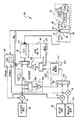
[0013] 図1を参照すると、本発明は、電力変換装置(電力コンバータ)22をAC電力網24に接続するため、およびこの電力コンバータを制御するために設計されたシステム20である。本発明により、任意の数の電力コンバータ22を、それら複数の電力コンバータ22に接続される別個の制御システムを必要とせずに、同じAC電力網24へ並列に接続することが可能となる。AC電力網24は、従来型のユーティリティ・グリッド又は分離した電力網とすることができる。システム20は、単相及び3相システムの何れに対しても働く。
[0013] Referring to FIG. 1, the present invention is a
[0014] システム20は、電池、フライホイール、光起電力パネル又は燃料電池などのDC電力源30とAC電力網24との間に接続される。具体的には、DC電力源30は、それが生成する電力が電力コンバータ22へ供給されるように、接続される。
[0014] The
[0015] 電力コンバータ22は、DC電力をAC電力に変換する任意の従来型のコンバータ、例えば、参照により本明細書に援用する米国特許第2,821,639号及び5,191,519号に記載のタイプのコンバータを含み得る。電力コンバータ22は、理想的な単位利得増幅器と考えることができる。実際、波形を追従することができる任意の装置が、本発明では、電力コンバータ22として含まれる。
[0015] The
[0016] 一実施形態では、電力コンバータ22は、出力を線形化するための補償(図示せず)及びパルス幅変調(PWM)制御(図示せず)を有するスイッチング電力コンバータ・ハーフ・ブリッジ(図示せず)とすることができる。一般に、この補償は不感時間補償であり、必要な場合にはDC入力電圧フィード・フォワードである。不感時間補償は、各PWM入力信号に対する少量の固定オフセットである。このオフセットは、出力電流の極性に応じて正か負の何れかとなる。このオフセットの振幅は、スイッチ不感時間とスイッチング期間との比に比例する。不感時間補償は、切替え(スイッチング)中の電圧制御の瞬時損失を補償するために提供される。DC電圧補償は、PWMへ行く信号を、それが不感時間補償へ行く前に、実際のDC電圧を公称DC電圧で割った値で割ることによって行われる。こうすると、電力コンバータの利得がDC電圧とは無関係になる。DC入力が良く制御されている場合には、この補償を行う必要がないこともある。
[0016] In one embodiment, the
[0017] 他の実施形態では、電力コンバータ22をインバータとしてよい。適当なインバータには、単相及び多相のあらゆるタイプのPWM又は共振型のインバータが含まれる。実際、増幅器又は電動機駆動装置のように基準波形を追従することができる、AC電力生成用の任意の電力インバータが含まれる。
[0017] In other embodiments, the
[0018] AC電力網24を、AC電力網の線路インピーダンス32、負荷インピーダンス34、及び有効EMF36によって概略的に示す。負荷インピーダンス34は、システム20により与えられる負荷に関連するインピーダンスであり、線路インピーダンス32は、AC電力網24にそれ以外に存在するインピーダンスである。負荷インピーダンス34は、極めて動的であり、しばしば非線形およびリアクタンス性である。線路インピーダンス32は、動的の度合いがより低く、通常は極めて誘導性であり得る。一般に、有効EMF36は、基本周波数が50又は60Hzで、予想される電圧の±10%以内の正弦波であり、一般に、基本周波数の奇数調波において最大で数%の高調波歪みを有し得る。AC電力網24は、システム20が用いられる環境であり、これは本発明を最も広く定義したときの一部である。AC電力網24は、ユーティリティ・グリッド又は分離した電力網であり得る。
[0018] The
[0019] システム20は、電力コンバータ22の出力とAC電力網24との間に接続されたフィルタ40を含み得る。一実施形態では、フィルタ40は、電力コンバータ22と線路インピーダンス32との間で互いに直列に接続されたインダクタ42及び44を含む減衰型のLCL T形フィルタである。また、フィルタ40は、互いに並列に接続され且つ負荷インピーダンス34に並列に接続されたコンデンサ46及び48と、コンデンサ46に直列に接続された抵抗50とを含む。コンデンサ46及び48は、インダクタ42と44との間の、フィルタ40のT点52に接続される。
The
[0020] この実施形態のフィルタ40により、電力コンバータ22からのリップルのフィルタリングが行われ、電力コンバータの電流を制御するインピーダンスが得られる。また、この実施形態のフィルタ40により、AC電力網24の負荷がシステム20の安定性に大きな影響を及ぼさないように、システム20の他のエレメントに対するある程度の高周波分離も提供される。この実施形態では、これらのインダクタは、約5%インピーダンス(60Hzにおける定格電圧を定格電流で割ったものの5%)であり、フィルタ40のコーナ周波数は約3kHzでありQは約4である。場合によっては、システム20からフィルタ40を省略することが望ましいことがあり、本発明には、当業者に周知の他のフィルタも含まれる。何れにしても、T点52におけるAC電力の特性は、電力コンバータ22の出力とAC電力網24との間にフィルタ40が配置されるために、線路インピーダンス32、負荷インピーダンス34、及び有効EMF36の影響を受ける。
[0020] The
[0021] システム20は、基準AC電圧コマンド信号の供給源60、実電流コマンド信号の供給源62、及び無効電流コマンド信号の供給源64も含む。供給源60から供給される基準AC電圧コマンド信号は電圧振幅である。供給源62からの実電流コマンド信号は電流振幅であり、供給源64からの無効電流コマンド信号も電流振幅である。以下に説明するように、供給源60、62及び64からの電圧及び電流の振幅の信号が、単位正弦波及び単位余弦波に乗算される。これらの供給源からの出力は、それぞれ、乗算器70、72及び74へ供給される。好ましくは、システム20にPLL(位相ロック・ループ)80が含まれる。PLL80は、線82を介してPLLへ入力として供給されるフィルタ40のT点52における電圧と正確に位相の揃った直接(正弦)波及び直角位相(余弦)波を生成する。これらの2つの波形は、入来する信号に正確に位相ロックした極めて純粋な正弦波であることが好ましい。当業者に周知の様々な位相ロック・ループの任意のものをPLL80として使用することができる。
[0021] The
[0022] PLL80として使用することができる1つの位相ロック・ループを図2に示す。このPLLの位相検出器は、XORゲート82である。また、この実施形態のPLL80は、ループ・フィルタ84、例えば、10Hzの1つのローパス・フィルタを含み、それによってXORゲート82の出力がフィルタリングされる。フィルタ84の出力は積分器86へ供給され、0.1Hzでゼロである。また、PLL80は、積分器86の出力を入力として受け取るサンプル・ホールド回路88を有する。PLL80は、サンプル・ホールド回路88の出力を受け取るように接続された電圧制御発振器(VCO)90を更に含む。VCO90は、余弦波形及び正弦波形の2つの波形を出力として生成する。VCO90は、その周波数の第2高調波を更に生成し、サンプル・ホールド回路88^サンプル入力として供給する。サンプル・ホールド回路88は、この第2高調波入力の関数として積分器86の出力をサンプリングする。
[0022] One phase-locked loop that can be used as
[0023] VCO90からの余弦波はXOR回路82へ入力されて、T点52で取り込まれた入力電圧波形と比較される。更に、この余弦波形は、乗算器70へ供給され、そこで、供給源60から供給される基準電圧振幅信号と乗算される。PLL80からの正弦波形は乗算器72へ入力され、そこで、供給源62から供給される実電流振幅信号と乗算され、また、乗算器74へも入力され、そこで、供給源64から供給される無効電流振幅信号と乗算される。
[0023] The cosine wave from the VCO 90 is input to the
[0024] VCOループ利得90の利得は、約1Hzで開ループ利得帯域幅積が1であるように選択する。こうすると、1Hzの閉ループ帯域幅を有する2次PLL及びトラッキング第2高調波ノッチ・フィルタが得られ、極めて純粋な出力波形が得られる。この2次の機能は、あらゆる周波数で位相誤差をゼロに強制するように用いられる。システム20には2次PLLは必要なく、これは、単に、位相誤差を極めて低くするのに優れた方法である。
[0024] The gain of the VCO loop gain 90 is selected such that the open loop gain bandwidth product is 1 at approximately 1 Hz. This provides a second order PLL and tracking second harmonic notch filter with a closed loop bandwidth of 1 Hz, resulting in a very pure output waveform. This secondary function is used to force the phase error to zero at any frequency.
[0025] また、システム20は、T点52における電圧を表す電圧信号と、電圧源60から供給される基準電圧信号とを入力として受け取るように接続された差分ユニット102を含む。図示しないA/Dコンバータ、スケーリング・デバイスその他の装置などの周知のエレメントを含む電圧信号デバイス103は、電力コンバータ22から実際の出力電圧を受け取り、次いで、この実出力電圧に基づいて、差分ユニット102へ供給される電圧フィードバック信号を生成する。差分ユニット102は、基準AC電圧信号と電圧フィードバック信号との電圧差を求め、この差を電圧差信号として利得器104へ供給する。差分ユニット102と利得器104とが共になってインピーダンス電流調整器106を構成する。
[0025] The
[0026] 利得器104は1/Rの利得を与える。ここで、Rは有効な実出力抵抗値である。Rは、電力コンバータ22の定格出力電圧を電力コンバータの定格出力電流で割り、その結果に、0.02〜0.2を、所望される性能、AC電力網24の特性、及び当業者に知られた他の要因に応じて、掛けることによって、求められる。典型的なAC電力網24において良好な性能を得るには、通常、Rは、定格出力電圧を定格出力電流で割った値に約0.05を掛けたものである。利得器104の出力はインピーダンス電流信号である。
[0026]
[0027] システム20は加算ユニット110を更に含む。加算ユニット110は、入力として、利得器104からのインピーダンス電流信号と、供給源62からの実電流信号と、供給源64からの無効電流信号とを受け取るように接続される。加算ユニット110は、これら3つの電流信号を加算して合成電流信号を生成する。場合によっては、加算ユニット110をインピーダンス電流調節器106の一部とみなすと有用なことがあるが、図面にはそのように示していない。
[0027] The
[0028] システム20には補正電圧ユニット112が含まれる。ユニット112は、加算ユニット110から合成電流信号を受け取り、次いで、電力コンバータ22を過電流状態から保護するために、出力として供給する電流に制限を加えるための電流制限器114を含む。補正電圧ユニット112は、また、電流制限器114から制限された電流信号を一方の入力として受け取る差分ユニット116を含む。差分ユニット116への他方の電流入力信号は、フィルタ40の前の、電力コンバータ22からの出力電流を表す出力電流信号である。この信号は、図には示さないA/Dコンバータ、スケーリング・デバイスその他の装置などの知られたエレメントを含む電流信号デバイス117によって生成される。差分ユニット116は、これらの電流信号の差を求め、次いで、電流差信号を利得器118へ供給する。利得器118からの出力は、電圧加算ユニット120へ供給される補正電圧信号である。この補正電圧と乗算器70から供給されるフィード・フォワード電圧信号とが加算ユニット120で合成され、本明細書では電圧コマンド信号とも称する制御電圧入力信号として電力コンバータ22へ供給される。図1では、電圧補正ユニット112が加算ユニット120を含まないように示しているが、場合によっては、この加算ユニットを電圧補正ユニットの一部として考慮すると有用である。
[0028] The
[0029] 利得器118を使用して、差分ユニット116、利得器118、加算ユニット120、電力コンバータ22、及びデバイス117からの電流フィードバック信号を差分ユニット116へ供給する線路122で構成される電流制御ループの帯域幅を制御する。この帯域幅を1〜2kHzに設定すると、システム20の適切な性能が得られるが、当業者には理解されるように、ある種の応用例では他の周波数が望ましいこともある。利得器118によって与えられる具体的な利得Pは、T点52からの電圧フィードバックの生成の責務を負う電圧感知回路(図示せず)のスケーリング・ファクタを含めて、所望の帯域幅B、フィルタ40のインダクタンス、及び電力コンバータ22の電圧利得Gに依存して決まる。一般に、利得Gの値は1に近い値である。即ち、この利得Gは、単に、電力コンバータ22の入力からT点52へ戻るまでの信号レベル利得である。従って、利得パラメータPは、2*π*B*L*/Gであり、ここで、Bは所望される帯域幅であり、Lはフィルタ40のインダクタンスである。
[0029] Using
[0030] 図3に示し、システム20aとして示すシステム20の簡略化したバージョンは、本発明の重要なインピーダンス電流調整の態様を強調して示す。システム20aはシステム20に類似しており、同じエレメントには同じ番号を有する。システム20aは、制御されたAC電力を供給する制御電流源128を含む。電流源128は、電力コンバータ22、DC電力源30、補正電圧ユニット112、及び加算ユニット120の代わりに使用し、それらと同じ機能を行う。しかしながら、制御電流源128は、一般化した制御電流源を表すことを意図したものであり、そのため、様々な実施形態を含み、システム20のエレメントの単なる組組み合わせだけに限定されないことを理解されたい。
[0030] A simplified version of
[0031] 加算ユニット110からの合成電流信号は、制御電流源128へ供給される。そこでは、電力コンバータ22の電流出力を表す電流フィードバック信号に対する差を求め、この電流差に利得Pを適用した後に、補正電圧信号が生成される。上述のように、この補正電圧信号を基準AC電圧信号と合成して、制御電流源128において電力コンバータ22用の電圧制御信号を生成する。制御電流源128からの出力は、フィルタ40を介してAC電力網24へ供給される。
[0031] The combined current signal from the
[0032] 一般に、システム20を構成する様々な要素は、電力コンバータ22を除き、電力コンバータ及びAC電力網24に接続されたコントローラ内のソフトウェア又はファームウェアで実施される。このため、典型的な実施形態のシステム20では、別個の回路要素やデバイスは使用しない。しかしながら、本発明は、ソフトウェア又はファームウェアだけ(電力コンバータ22の出力から必要な電流及び電圧フィードバック信号を提供する関連の装置を伴う)で本発明を実施する形態に加えて、別個の回路エレメント及びデバイスとして実施する形態も含む。
[0032] In general, the various elements that make up
[0033] 次に、システム20(図1)とシステム20a(図3)とを参照して、
ACエネルギが制御電流源128からフィルタ40を介してAC電力網24へ供給される本発明の動作を論じる。インピーダンス電流調整器106は、AC電力網24の、制御電流源128からの電流の変化を吸収する能力に基づいて、制御電流源128から供給される実電流及び無効電流に影響を及ぼす。これに関しては、調整器106から供給されるインピーダンス電流信号と、供給源62及び64からそれぞれ供給される実電流信号及び無効電流信号とが合成されて、制御電流源128から供給されるAC電力の実電流及び無効電流が最終的に変更される。
[0033] Next, referring to system 20 (FIG. 1) and
The operation of the present invention will be discussed in which AC energy is supplied from the controlled
[0034] インピーダンス電流調整器106から供給されるインピーダンス電流信号は、(i)AC電力網24の線路インピーダンス32、負荷インピーダンス34及び有効EMF36により、および(ii)制御電流源128からの出力電力の特性りより、影響を受ける。インピーダンス電力信号に対するこの影響は、フィルタ40のT点52からの電圧フィードバック信号が電流調整器106の差分ユニット102へ供給されることによって、および電力コンバータ22の出力電力からの電流フィードバック信号がフィルタ40の前に差分ユニット116へ供給されることによって、生じる。電圧フィードバック信号に関しては、加算ユニット110へ供給されるインピーダンス電流信号は、T点52からの電圧フィードバック信号と、供給源60(その正弦波はPLL80の出力によって制御される)からの基準電圧信号との間の差に基づいており、電流調整器106内で生成される。即ち、最終的に制御電流源128の出力に影響を及ぼす、利得器104への電圧信号入力は、AC電力網24上の優勢な電圧と、基準電圧振幅(供給源60から)とに基づいており、その正弦波形は、PLL80によって、T点52におけるAC電力の正弦波形に対して制御されている。線122上の電流フィードバック信号に関しては、差分ユニット116で決まる、この信号と、加算ユニット110からの合成電流コマンド信号との間の差により、電力コンバータへ供給される電圧制御信号が、電力コンバータ22からのAC出力電力の電流によって部分的に影響を及ぼされるようにする。
[0034] The impedance current signal supplied from the impedance
[0035] インピーダンス電流補正の量は、利得ユニット104の利得(1/R)によって制御される。Rの値は、電力コンバータ22の有効出力抵抗を表すので、この利得は1/Rで表される。即ち、この利得により、供給源60からの基準電圧とT点52からの電圧フィードバック信号との各電圧差ごとに電力コンバータ22が供給するアンペア数が制御される。
[0035] The amount of impedance current correction is controlled by the gain (1 / R) of the
[0036] 上述のように、利得器118が提供する利得Pは、部分的には、電流制御ループの所望される帯域幅の関数として選択される。1〜2kHzの範囲の帯域幅が一般的であるが、本発明はこの範囲に限定されるものではない。システム20の能力は、その後ろにあるDC電力源30によって制限される。多くの場合、DC電力源30は正の電力のみを供給することができ、その電力のレベルはゆっくりと変化する。他の場合には、DC電力源30は、限定された量のエネルギのみを蓄積する。このエネルギ蓄積の電力レベルは急激に変わることがあるが、使用後は再充電しなければならない。AC電力網24へ、或いはそれから電力を供給する機能を実施するとき、システム20は、単に、ACシステムの要求を考慮に入れた双方向のDC/AC電力コンバータである。
[0036] As noted above, the gain P provided by the
[0037] 加算ユニット110から制御電流源128へ供給される合成電流信号は、供給源62からの実電流信号の振幅と、PLL80によって与えられる正弦波形との関数として生成される。この実電流信号を用いて、AC電力網24へ接続された他の機器に対しての或る特定のDC電力源からの実電力の流れを制御する。この実電流信号は、正または負の何れかとすることができる。エネルギ蓄積能力を用いて供給源を再充電すには負の値を用いる。
[0037] The combined current signal supplied from the adding
[0038] 加算ユニット110から制御電流源128へ供給される無効電流信号は、供給源64からの無効電流信号の振幅とPLL80によって与えられる余弦波形との関数として生成される。この無効電流信号を用いて、AC電力網24へ接続された他の機器に対しての無効電力の流れを制御する。この無効電流コマンド信号を用いて、電力コンバータ22からの出力電流の力率を制御して負荷に対する補償を行うか、或いは、AC電力網24へ無効電力を供給することができる。無効電流信号の余弦波形は、実電流コマンド供給源62から生成される正弦波形から90度位相がずれており、正または負の何れかとすることができる。
[0038] The reactive current signal supplied from the
[0039] 供給源60、62又は64からシステム20へのこの3つの入力パラメータは、システム20内で制御することができ、また、外部コマンドに基づくものとすることもできる。システム20により提供される制御は、電力コンバータ22がこれら3つの供給源からのコマンド信号を厳密に追跡することを許容しないことに留意されたい。なぜなら、AC電力網24のローカルの電圧及びインピーダンスにも応答しなければならないからである。システム20のこの特性は、上述のように、インピーダンス電流調整器106からのインピーダンス電流を使用するので生じるものである。システム20は、T点52からの出力電圧信号を用いて、電流コマンド、具体的にはインピーダンス電流信号を変更して、出力電圧が範囲外に大きく外れないようにする。障害時に、インピーダンス調整が高速実時間ルーチンで実施されるので、障害が解消されると、大きくオーバーシュートすることなく電圧は正常値に迅速に回復する。同様に、電圧サージへの対処がなされ、他の機器に支障をきたすことはない。
[0039] The three input parameters from the
[0040] 図3及び図4を参照すると、システム20及び20aでは、電流制御ループが電圧制御ループの内部にあり、特定の利得1/Rを有する。図4においてシステム20bに関して示すように、本発明は、別の実施形態として、これらの制御ループを裏返しにすることを含む。システム20bとシステム20aとが同じ箇所では、共通のエレメントに同じ番号が付けられている。しかしながら、重要な差異は、制御電流源128の代わりに制御電圧源140が用いられていることである。制御電圧源140は、入力制御信号が電流信号ではなく電圧信号である点を除き、制御電流源128と同様である。
[0040] Referring to FIGS. 3 and 4, in
[0041] システム20aとシステム20bの別の差異は、インピーダンス電流調整器106も加算ユニット110も含まれていないことである。供給源62及び64からの実電流コマンド信号及び無効電流コマンド信号は、それぞれに、加算ユニット142で合成され、加算電流信号としてインピーダンス電流調整器144へ供給される。インピーダンス電流調整器144は差分ユニット146を含み、この差分ユニット146は、加算ユニット142からの加算電流信号と、制御電圧源140内の電力コンバータ22(図示せず)のAC電力出力の出力電流を表すデバイス117からの電流フィードバック信号との間の差を表す差分信号を生成する。このフィードバック電流は、制御電圧源140を制御するのに用いるインピーダンス電流と考慮することができる。また、インピーダンス電流調整器144は、差分ユニット146からの差分信号に利得Rを適用する利得ユニット148を含む。利得器148への入力は電圧ではなく電流であるので、利得器148では、利得1/Rではなく利得Rを用いる。Rの値は、システム20の説明に関連して上述している。図には示していないが、加算ユニット142からの加算電流を制限するために、電流制限器112に類似の電流制限器をシステム20bに含めることが好ましい。
[0041] Another difference between
[0042] 動作において、システム20bによって提供される制御方法は、上述したようにシステム20aのものとかなり似ている。注目すべき差異は、(1)電流制限機能を付加する簡単な場所がないことと、(2)電流ループの内部に電圧ループがあるので、電圧過渡応答が電流応答よりも速くなることとのみである。
[0042] In operation, the control method provided by system 20b is quite similar to that of
[0043] 次に、図5−1及び5−2に移ると、システム20cとして示す本発明の別の実施形態では、システム20のインピーダンス電流調整器106の代わりに、インピーダンス電流調整器106’が用いられている。その他の点では、システム20cはシステム20と同じである。
[0043] Turning now to FIGS. 5-1 and 5-2, in another embodiment of the present invention shown as
[0044] インピーダンス電流調整器106’は、フィルタ40のT点52から電圧フィードバック信号を受け取るように接続されたRMSユニット160と、乗算器70からフィード・フォワード基準AC電圧を受け取るように接続されたRMSユニット162とを含む。RMSユニット160及び162は、それらが受け取る電圧信号の自乗平均値を決定し、出力としてRMS電圧信号を供給する。
[0044] Impedance
[0045] インピーダンス電流調整器106’は、また、入力として供給されるRMS電圧信号間の差を求める差分ユニット164を含む。差分ユニット164は、このRMS電圧信号の差を表す差分信号を生成し、それをABSユニット166へ供給する。ABSユニット166は、この差分信号の絶対値をとり、その結果をロー・パス・フィルタ168へ供給する。ロー・パス・フィルタ168は、この差分をフィルタリングして、RMS差分信号に対する所望される応答時間を提供する。次いで、このフィルタリングされた電圧差分信号は、利得ユニット170へ供給され、そこで、フィルタ168からのフィルタリングされた差分信号に利得関数が適用される。一実施形態では、利得ユニット170は、加算ユニット172と、この加算ユニットへ1/R1の利得信号を提供する利得器174を含む。利得ユニット170は、フィルタ168からのフィルタリングされた電圧差分信号に対して1/R2の利得を強要する利得器176を更に含み、その結果を加算ユニット172へ供給する。加算ユニット172は、1/R1信号と1/R2利得の電圧差分信号を合成して、乗算器178へ供給されるインピーダンス電流信号を生成する。
[0045] The impedance current regulator 106 'also includes a
[0046] 乗算器178で、このインピーダンス電流信号は、差分ユニット102からの電圧差分信号と合成され、加算ユニット110へ供給される。システム20と関連して上述したように、加算ユニット110から供給される合成電流信号は、電圧補正ユニット114の電流制限器114へ供給される。
[0046] In the
[0047] 上記では、利得ユニット170は特定の機能を実現するために特定の組のエレメントを含むものとして説明した。利得ユニット170は他の機能も実施することができ、本発明は、上述の利得ユニットの実施形態によって実現される特定の機能及びこのような実施形態に含まれる特定のエレメントに限定されるものではない。
[0047] The
[0048] 動作においては、システム20cにより、差分ユニット102の出力に印加される利得1/Rが、RMSユニット160と162それぞれからの電圧フィード・フォワード信号と電圧フィードバック信号とのRMS値の差に比例して、増加する。システム20cの制御方法は応答をもたらし、その応答では、T点52におけるAC電圧が公称AC電圧から外れると、それに比例して低いインピーダンス(より大きな復元電流)が与えられることになる。1/Rの有効値は、1/R1+[rms(Vff)−rms(Vfb)]/R2である。ここで、Vffは、乗算器70からの電圧フィード・フォワード信号であり、Vfbは、T点52からの電圧フィードバック信号である。フィルタリングすると、短時間(ライン・サイクル内)、この期間は制御回路が大きく応答せずに、電圧フィードバックが外れる。しかしながら、電圧がより長い時間にわたって変化する場合、システム20cは、より大きな復元電流を供給することになる。こうすると、基本的電圧差に対しては比較的大きな補正を与えながら、高調波に対する補正は少なくすることができるようになる。これは、高調波補正の必要がない大きな高調波負荷を有するシステムでは有用である。
[0048] In operation, the
[0049] R2+R1の値は、R2がR1にほぼ等しい状態で、電力コンバータ22の定格出力電圧をその定格出力電流で割ったものの3%〜10%程度、典型的には約5%とすべきである。ある種の応用例では、正反対の応答が望ましいことがある。この場合、R2の値は負となろう。こうすると、高調波に対する補正は大きくなり、基本電圧に対する補正はより小さくなろう。これは、エネルギの蓄積がほとんど或いは全くない高調波フィルタの応用例では有用となろう。この場合のR2値はR1よりも小さく、その符号は負である。
[0049] The value of R 2 + R 1 is about 3% to 10% of the rated output voltage of the
[0050] 場合によっては、インピーダンス電流調整器106が、選択した周波数、例えば基本周波数(50又は60Hz)に対してのみ低いインピーダンス(高い補正電流)を与えると望ましいことがある。図1及び6を参照すると、これを、システム20のインピーダンス電流調整器106(図1)の代わりに、システム20dにおいてインピーダンス電流調整器106’’(図6)を含めることによって、実現することができる。インピーダンス電流調整器106’’は、インピーダンス電流調整器106と同様に、差分ユニット102及び1/R利得器104を含む。更に、インピーダンス電流調整器106’’は、PLL80からの正弦波形及び差分ユニット102からの電圧差分信号を入力として受け取るように接続される乗算器192を含む。乗算器192は、この正弦波形に電圧差分信号を乗算する。この正弦波形は、T点52における出力電圧と正確に同相であるので、正弦波形に電圧差分信号を掛けると、DCへ行く選択した周波数、典型的には基本周波数となる。
[0050] In some cases, it may be desirable for the impedance
[0051] このDC電圧差分信号は、場合によっては関連する高調波であっても、ローパス・フィルタ194へ供給される。このフィルタにより、DC電圧差分信号に存在する高調波が取り除かれ、その出力は、差分ユニット102で決定された電圧差の振幅になる。この振幅に、利得器196で利得1/R2を乗算する。利得1/R2は、特に対象とする入力の大きさの増加を伴いながら1/R2の値を増加させる非線形関数を含めて、任意の関数とすることができる(本発明には線形関数も含まれる)。実際には、R2の値は、1/R2の逆数が、電力コンバータ22の定格出力電圧をその定格出力電流で割ったものの2%〜10%となるように選択することができる。利得器196の出力は、選択されたインピーダンス電流信号である。
[0051] This DC voltage difference signal is supplied to the
[0052] インピーダンス電流調整器106’’は、また、供給源64からの無効電流コマンド信号に、利得器196からの選択されたインピーダンス電流信号を加算する加算ユニット198を含む。この加算の結果は、加算ユニット198から乗算器72へ供給される。
[0052] The impedance
[0053] 動作において、システム20dにインピーダンス電流調整器106’’を含めることにより、選択した周波数、例えば50又は60Hzにおいてのみインピーダンス電流信号の振幅が増加する。これは、基本電圧を調整するために、基本周波数における補正電流が高いことが望まれるときに、望ましい。一例は、出力レベルを迅速に変更することができない分離型またはソフト・グリッドにおける電力の主供給源である。
[0053] In operation, the inclusion of the impedance
[0054] 次に、図1及び図7を参照すると、システム20e(図7)に示すように、場合によっては、加算ユニット120(図1)へ供給され、電圧フィード・フォワード信号と合成されて電力コンバータ22へ供給される電圧フィード・フォワード信号を除くことが望ましいことがある。このため、システム20eでは、乗算器70から電圧フィード・フォワード信号が供給されず、加算ユニット120が取り除かれる。
[0054] Referring now to FIGS. 1 and 7, as shown in
[0055] システム20eの動作で電圧フィード・フォワード信号を使用しないことによって生じる影響は、電流ループにおける利得Pをより高くする必要があることである。一般に、電圧フィード・フォワードが望まれるが、システム20の帯域幅が極めて高い場合、電圧フィード・フォワード信号を除くことができる。
[0055] The effect caused by not using a voltage feed-forward signal in the operation of the
[0056] 図8のシステム20fで示すシステム20eの代替形態では、T点52からの電圧フィードバック信号を電圧フィード・フォワード信号として用いることができる。即ち、T点52からの電圧フィードバック信号は、差分ユニット102及び加算ユニット120の両方へ供給される。動作においては、本明細書で論じたシステム20の他のバージョンと同様の性能が得られる。
[0056] In an alternative form of
[0057] 最終的に電力コンバータ22へ供給される電圧フィード・フォワード信号を生成する別の方法を、システム20gに関して図9に示す。この実施形態では、システム20fの場合と同様に、乗算器70からフィード・フォワード電圧が受信されない。その代わりに、T点52からの電圧フィードバック信号がRMSユニット210へ供給され、そこで、この電圧フィードバック信号の自乗平均値が求められる。次いで、このRMS電圧信号が乗算器212へ供給され、そこで、このRMS電圧信号に、PLL80から正弦波形が加えられる。次に、乗算器212から出力信号が加算ユニット120へ供給され、そこで、利得器118からの補正電圧信号と合成され、次いで、電力コンバータ22へ供給される。
[0057] Another method for generating a voltage feed-forward signal that is ultimately supplied to the
[0058] システム20gの動作は、加算ユニット120から電力コンバータ22へ供給される電圧信号が、予想電圧(図1に示すシステム20の場合はそうである)ではなく、T点52における出力電圧の実際の振幅の関数である、ということの影響を受ける。こうすると、予想電圧と実際の電圧のRMS値とが整合するので、本発明はRMS電圧を制御する試みを過分に行わないことになる。本発明のこのバージョンは、電圧源として動作し且つRMS電圧が比較的大きく変動する中央システムと並列にシステム20gを配置することになる状況には理想的である。
[0058] The operation of the
[0059] 次に、図1並びに図10−1、10−2及び10−3に移ると、システム20hに関して図10−1、10−2及び10−3に示すように、上記のシステム20及び20a〜g或いは本発明の範囲に含まれる他の代替形態の任意のものを、3相4線型の環境で実施することができる。重複を最小限に抑えるために、システム20hでは、システム20から電圧フィードバック及びフィード・フォワードの信号方式のみを示す。しかしながら、本発明は、システム20hにおいて、システム20及び20a〜20g、或いは本発明の範囲に含まれる他の任意の制御方式を使用することが含まれる。即ち、システム20hの検討に関連して、並びに図11−1、11−2、11−3及び12〜16に示す本発明のシステム20の他の実施形態の検討において、システム20(及びこのシステムを示す関連の図1)を参照することは、図1に示す特定のシステム20、システム20a〜20g、並びに本発明の範囲に含まれるこれらのシステムの他のすべての変形形態が包含されることを意図するものである。従って、本発明の以下の説明において、システム20及びこのシステムを示す図1を参照することは、本発明の制御システムのすべての変形形態を示すのに単に好都合な方法であり、図1に示す特定のシステムだけに本発明を限定するものではない。、図1並びに図10−1、10−2及び10−3では、図10−1、10−2及び10−3において場合によってプライムを表記して同じ要素の複数の具体例を区別していることを除き、同じ要素は同じ参照番号で示す。
[0059] Turning now to FIG. 1 and FIGS. 10-1, 10-2, and 10-3, the
[0060] システム20hは、3つの単相システムを備え、これら3つの相のそれぞれの制御のために1つのシステムがある。システム20hは電力コンバータ22’を含み、この電力コンバータ22’は、出力ノードA、B及びCで各相ごとにAC出力電力を供給するように設計され、かつ接地への出力ノードNを含む点を除き、電力コンバータ22と類似である。電力コンバータ22’は、入力制御信号を受け取る入力ノードA、B及びCを含む。電力コンバータ22’として、6スイッチ型ブリッジを有する電力コンバータを満足のいくように用いることができるが、電力コンバータ22に関して上述したように、広い範囲の電力コンバータ及びインバータを電力コンバータ22’として用いることができる。ノードA、B及びC又は電力コンバータ22’からAC電力出力をそれぞれ受け取るように、3つのフィルタ40’、40’’及び40’’’が設けられる。
[0060]
[0061] システム20hは、また、実電流コマンド信号の供給源62及び無効電流コマンド信号の供給源64を含む。供給源62からの実電流コマンド信号は、乗算器72’、72’’及び72’’’へ供給され、無効電流コマンド信号は、供給源64から乗算器74’、74’’及び74’’’へ供給される。これら3つのすべての相に対して共通のAC実電流源及びAC無効電流源を用いるが、所望される場合には別々の供給源を用いることができる。システム20hは、基準AC電圧を供給する3つの供給源60’、60’’及び60’’’を含む。供給源60’からの電圧信号は振幅Aを、供給源60’’からの電圧信号は振幅Bを、供給源60’’’からの電圧信号は振幅Cを有する。典型的には、振幅A、B及びCはすべて同じであるが、一般には、これらの振幅のいくつか又はすべてを異なるものとすることができる。システム20hは、セクション230、232及び234を有する3相PLL80’を含み、各セクションは、他のセクションの位相とは異なる位相を有する正弦波形信号及び余弦波形信号を生成する。
[0061] The
[0062] PLL80に関して上述のように、本発明の範囲には、当業者に知られたタイプの広範囲のPLLが含まれる。セクション230は、その入力としてフィルタ40’のT点52’から信号を受け取り、セクション232は、その入力としてフィルタ40’’のT点52’’から信号を受け取り、セクション234は、その入力としてフィルタ40’’’のT点52’’’から信号を受け取る。セクション230からの正弦波形信号は、乗算器70’及び乗算器72’へ供給され、セクション230からの余弦波形信号は、乗算器74’へ供給される。同様に、セクション232からの正弦波形信号は、乗算器70’’及び乗算器72’’へ供給され、セクション232からの余弦波形信号は、乗算器74’’へ供給される。また、セクション234からの正弦波形信号は、乗算器70’’’及び乗算器72’’’へ供給され、セクション234からの余弦波形信号は、乗算器74’’’へ供給される。セクション230、232及び234のそれぞれにおけるPLLは同期して、オン/オフ制御を簡略化する助けとなるが、これは本発明の必須の態様ではない。
[0062] As described above with respect to
[0063] システム20hの各相のセクションは、上述のように、システム20と同様に機能する。即ち、例えば、乗算器70’、72’及び74’から入力信号を受け取る相セクションは、これらの信号を用いて、最終的に加算ユニット120から電力コンバータ22’の入力ノードAへ制御電圧入力信号を供給する。同様の制御電圧入力信号が、他の2つの相用の加算ユニット120から電力コンバータ22’の入力ノードB及びCへ供給される。次いで、電力コンバータ22’は、入力ノードA、B及びCで受け取ったこれらの制御電圧入力信号に従って、DC電力源から供給されたDC電力をAC電力に変換し、フィルタ40’、40’’及び40’’’を介してAC電力網(図示せず)へ3相出力電圧を供給する。電動機駆動及びコンバータ制御の技術者には理解されるように、上記4線型の制御に加えて、中性コントローラを備えた3線型コントローラに基づく他の構成があり、これは、以下に示すものと同様な方法でコントローラを再構成することによって4線型の制御に用いることができる。
[0063] Each phase section of
[0064] 本発明の電力コンバータ制御システムは、システム20iに関して図11−1、11−2及び11−3に示すように、3相3線型電力システムにも適用することができる。システム20hの場合のように3つの電流制御ループを含む代わりに、システム20iは2つの電流制御ループのみを含むが、それは、2つの電流のみを制御するからである。即ち、電力コントローラ22aは、出力ノードA、B及びCのみを含み、ノードNを含まない点を除き、電力コントローラ22’(図10−1及び10−2)と同様である。第1電流制御ループは、その入力として、乗算器70aからの基準電圧信号、乗算器72aからの実電流コマンド信号、及び乗算器74aからの無効電流コマンド信号を含む。第2電流制御ループは、その入力として、乗算器70bからの基準電圧信号、乗算器72bからの実電流コマンド信号、及び乗算器74bからの無効電流コマンド信号を含む。
[0064] The power converter control system of the present invention can also be applied to a three-phase three-wire power system as shown in FIGS. 11-1, 11-2 and 11-3 with respect to the system 20i. Instead of including three current control loops as in
[0065] システム20iは、T点52’、52’’及び52’’’からの電圧フィードバック信号がクラーク・トランスフォーマ240へ供給されるという点で、システム20hと更に異なる。このトランスフォーマは、電力コンバータ22aからの3相入力信号を、PLL80aへ供給される直接(D)電圧フィードバック信号及び直角位相(Q)電圧フィードバック信号に変換する。このPLLは、直接(D)電圧フィードバック信号と同相の直接(d)出力正弦波形、及び直角位相(Q)電圧フィードバック信号と同相の直角位相(q)出力正弦波形を生成する。この直接(d)出力正弦波形は直接に乗算器70a及び72aへ供給され、直角位相(q)出力正弦波形は直接に乗算器74a、70b及び72bへ供給される。PLL80aからの直接(d)出力正弦波形は反転利得器242へも供給され、そこで、正弦波形の符号が変更(位相を180度シフト)され、次いで、得られた正弦波形を乗算器74bへ供給する。
[0065] System 20i further differs from
[0066] PLL80aは、また、3線型電力コンバータが最小DC入力電圧で動作するのに必要なことがあるAC中性点とDC中性点の間の差分の制御に用いる中性点フィード・フォワード信号(NPFF)を生成する。典型的には、このNPFF信号は、電力コンバータ22のフルスケール電圧の約14%を表す第3高調波信号である。このNPFF信号は、電力コンバータ22aによりNPFFノードを介して加算ユニット250及び252へ供給される。加算ユニット250は、このNPFF信号に、システム20iの上部の電流制御ループにある加算ユニット120’からの電圧信号を加算し、加算ユニット252は、このNPFF信号に、システム20iの下部の電流制御ループにある加算ユニット120’’からの電圧信号を加算する。PLL80aへ供給される前に、直接(D)フィードバック信号は直接に上部の電流制御ループの差分ユニット102’へも供給され、直角位相(Q)電圧フィードバック信号は直接に下部の電流制御ループの差分ユニット102’’へも供給される。
[0066] The
[0067] システム20iは、また、入力ノードA及びBで電力コンバータ22aの出力ノードB及びCからそれぞれ電流フィードバック信号を受け取るように接続されたクラーク・トランスフォーマ254を含む。クラーク・トランスフォーマ254の入力Cは、電力コンバータ22aの出力ノードB及びCからの電流フィードバック信号が加算され反転された値を受け取る。これは、これらの電流フィードバック信号を加算ユニット256へ供給し、次いで、この加算された電流信号を反転利得器258へ供給することによって実現される。次いで、反転利得器258からの反転電流信号出力は、クラーク・トランスフォーマ254の入力ノードCへ供給される。クラーク・トランスフォーマ240と同様に、クラーク・トランスフォーマ254は、その3つの電流信号入力を、直接(D)電流フィードバック信号及び直角位相(Q)電流フィードバック信号の2つの電流信号出力に変換する。この直接(D)電流フィードバック信号は、図11−1のシステム20iの上部の電流制御ループの差分ユニット116’へ供給され、直角位相(Q)電流フィードバック信号は、図11−2のシステム20iの下部の電流制御ループの差分ユニット116’’へ供給される。
[0067] System 20i also includes a
[0068] 電力コンバータ22aには、各相ごとに1つの、3つの入力制御信号が必要なので、逆クラーク・トランスフォーマ260が設けられる。加算ユニット120’及び120’’からの電圧制御信号は、それぞれ、PLL80aからのNPFF信号と合成され、次いで、逆クラーク・トランスフォーマ260の入力ノードD及びQへ供給される。次いで、逆クラーク・トランスフォーマ260は、ノードA、B及びC上に、電力コンバータ22aへ供給される出力制御信号を生成する。電力コンバータ22aは、これらの制御信号に基づいて、DC電力源30からのDC電力をAC電力に変換し、それぞれ出力ノードA、B及びCを介してフィルタ40’、40’’及び40’’’へ、次いで、AC電力網(図示せず)へ供給する。
[0068] Since the
[0069] システム20iは、別々の制御セクションを用いるという点でシステム20hと同様に機能する。しかしながら、システム20iは、2つの制御セクションまみを含み、クラーク・トランスフォーマ240及び254並びに逆クラーク・トランスフォーマ260を使用するので、3相3線型電力システムで使用することができる。なぜなら、ia+ib+ic=0とした場合に、制御するのは実際には2つのみの独特の電流であるからである。
[0069] System 20i functions similarly to
[0070] 次に、図1及び12に移ると、本発明の制御システムがモデル300で表されている。乗算器72及び74からの信号の加算から与えられる電流コマンド信号は、従属電流源(IAC)302を制御するものと考慮することができ、乗算器70の出力から供給される電圧コマンド信号は、従属電圧源(VAC)304を制御するものと考慮することができる。これらの供給源は、互いにかつAC電力網24に並列に接続され、出力電圧に同期すると考慮されなければならない。有効抵抗値(Reff)306は、VAC源304とIAC源302との間に接続される。Reff306は、本発明の制御システムによって提供されるインピーダンス制御を表す。Reffの値は、上述のインピーダンス電流調整器106の利得器104のRと同じである。Reffは、実際の抵抗ではなく、電力損失がなく、単に、電力コンバータ22の模する抵抗値を表すものであることに留意されたい。
[0070] Turning now to FIGS. 1 and 12, the control system of the present invention is represented by a
[0071] モデル300は、抵抗314に直列に接続されたコンデンサ312を有するフィルタ310を含む。このコンデンサ/抵抗の組み合わせは、IAC302及びVAC304に並列に接続される。第2コンデンサ316が、フィルタ302に設けられ、コンデンサ312及び抵抗314に並列に接続される。フィルタ310は、コンデンサ316とAC電力網24との間にインダクタ318を更に含む。フィルタ302は、フィルタ40(図1)のインダクタ44のような第1インダクタを含まない。なぜなら、電流制御ループの内部へそれを包含することに起因してのこの実モデルの性能への影響がないからである。
[0071]
[0072] モデル300を用いて、本発明の制御システムの動作を理解することができる。供給源62及び64からの電流コマンド信号がゼロであり、供給源60からの電圧コマンド信号が、T点52における電力コンバータの出力電圧と等しい場合、電力コンバータから電流が出ないことになる。出力電圧の乱れがある場合、電流がVAC304からAC電力網24へ流れ、その電圧を元の値に戻す助けとなる。この乱れは、電圧の上昇または下降、高調波電圧またはスイッチング過渡、或いはその電圧を所望される電圧においての純粋な正弦波から逸脱させる他のものであり得る。
[0072] The
[0073] 上記のようにT点52と乗算器70とからの電圧が合致し、電流コマンドが加えられる場合を考える。AC電力網24が剛直な低インピーダンス網であり、電力コンバータ22がこの低インピーダンス網電力の小部分であるとき、電流コマンドは、T点52における電圧変化をほとんど伴わずにAC電力網へ送られることになる。このため、インピーダンス電流調整器106は、加算ユニット110の出力で供給される電流コマンド信号を大きく変更しないことになる。しかし、電力コンバータ22がAC電力網24の大きな因子であり、この電流が網上に与えられると電圧が大きく変化する場合は、調整器106を含むインピーダンス電流制御ループがその電流を大きな割合で引き戻し、それによって、電力網の電圧を許容差内に保つことになる。
[0073] Consider a case where the voltage from the
[0074] システム20及び上記で論じたその変形形態及びその他の本発明に含まれる形態を個々に用いることができるが、複数のシステム20を、単一又は複数の負荷と並列に接続すると、望ましい結果が得られる。次に、図1、12及び13を参照し、システム20を示す簡便な方法としてモデル300を用いると、システム20jに関して示すように(図13)、システム20’、20’’及び20’’’として識別する複数のシステム20を、AC電力網24に並列に接続することができる。図13に、3つのシステム20を並列接続で示すが、2つ又は4つ以上、いくつかの応用例では実質的に3つよりも多くの数を、並列構成で使用することができることを理解されたい。
[0074] Although the
[0075] 次に、図1及び12〜14に移ると、システム20kに関して図14に示すように、単一の負荷34をサポートする代わりに、システム20’、20’’、20’’’をそれぞれ、別々の負荷インピーダンス34’、34’’、34’’’へ接続することができる。システム20kでは、変圧器330’、330’’及び330’’’は、負荷インピーダンス34’、34’’及び34’’’へ、負荷インピーダンスと単一線路インピーダンス32及びEMF36との間で、それぞれ並列に接続される。システム20が互いに近接している場合には、変圧器330’、330’’及び330’’’は必要ない。図14では3つのシステム20を並列接続で示すが、この場合も、2つ又は4つ以上、いくつかの応用例では実質的に3つより多くの数を、並列構成で使用することができることを理解されたい。
[0075] Turning now to FIGS. 1 and 12-14, instead of supporting a
[0076] 並列にされたシステム20k及び20jによって、様々な利益が得られる。電流にサージがある場合、システム20’、20’’、20’’’のすべてがこの状況に対処するために共同して働く。なぜなら、各システムの動作は、AC電力網24の電力特性(T点52からの信号の情報に基づく)によって部分的に影響を受けるからである。
[0076] Various benefits are obtained by the
[0077] システム20’、20’’、20’’’を並列に接続することによって、関連するDC電力コンバータ22から大量の電流を供給して、電流障害を取り除くことができる。サージの場合には、電圧をサポートして、AC電力網24に接続された機器を過電流状態から保護する。これは、システム20’、20’’及び20’’’のそれぞれが共になって働き、サージがなくなるまで、関連するDC電力供給源30によって電圧及び電流が最適に供給および/または吸収されるからである。システム20jにより、共同して働く多数の小型システムから構成される信頼性の高い電力システムが得られる。
[0077] By connecting the
[0078] 本発明により、複数の小型で安価な電力コンバータ22を使用することもできる。それらの電力コンバータを合わせても、AC電力網24の全負荷に対する要件に適した単一の電力コンバータよりもコストが低い。大規模な網(例えば、5つ以上のシステム20)では、個々の電力コンバータ22の最大電力定格は、各ユニットがそれ自体の最大電力を供給しなければならない場合よりも低くなり得る。例えば、独立型燃料電池の住居用仕様では、平均電力7kW及び最大(ピーク)定格20kWが必要なことがある。システム20kでは、AC電力網24で10個のシステム20を接続すると、連続的電力定格7kW及び最大10kWが得られるはずである。この場合、システム負荷合計に応じて、一度に2つ以上の負荷が最大(ピーク)となり得る。別の考え方をすると、システム20k全体では、比較的小型で安価な電力コンバータ22を組み込んだシステムによって、連続電力定格70kW、最大100kWの負荷を動作させることができる。
[0078] According to the present invention, a plurality of small and
[0079] システム20kの別の動作を考えると、各電力コンバータ22に関連するDC電力源30を使用して、広範囲に分散した配電システムで、複数の負荷をサポートすることができる。この網は、3相工業用網又は単相住居用網とすることができる。このタイプの応用例では、システム20’、20’’及び20’’’のすべてが、負荷インピーダンス34’、34’’及び34’’’で示す基本負荷、線路インピーダンス32で示す線路負荷、EMF36、及び関連する最大値、過渡状態及び高調波を、分担する。
[0079] Considering another operation of the
[0080] 典型的な実施形態では、システム20j及び20kは、重要な冗長性の恩恵を享受している。システム20’、20’’及び20’’’のそれぞれが、双方向エネルギ源、例えば、過渡用の電池を備えた燃料電池などによってサポートされていると仮定する(ここでは、任意の数のシステム20を備えることができ、実際に、その数が多いほどシステムは良好に働く)。また、任意の3つのエネルギ源の合計容量が負荷をサポートできると仮定する。ここでは、4つの供給源、3つのDC電力源30、及びAC電力網24がある。システム20j及び20kは、動作を保つのには3つの供給源のみを必要とすることから、冗長性を内包している。この冗長性を簡単に理解するには、システム20’、20’’及び20’’’がすべて等しいサイズであると仮定する(任意のサイズであり得るとしても)。
[0080] In an exemplary embodiment,
[0081] 次に、図1及び図15を参照すると、分散型発電(DG)電力網400においてシステム20を有利に使用することができる。図15に示すDG網400は、住居用網である。しかしながら、システム20を使用し得るDG網400は、住居用、商業用及び工業用の電力消費体(および、場合によっては電力供体)の任意の組合せを含むことを理解されたい。
[0081] Referring now to FIGS. 1 and 15, the
[0082] DG網400は、AC電力網24、例えばユーティリティ・グリッド、に接続可能である。AC電力網24とDG網400とを選択的に接続および接続解除するためにユーティリティ・スイッチ404を設けることができるが、このスイッチは必須ではない。DG網400は、例えば、フライホイール蓄積システム406、光起電力システム408、及び燃料電池410などのDC電力源を1つ又は複数含む。フライホイール蓄積システム406は、フライホイール412、アクティブ型整流器414、及びシステム20を含む。光起電力システム408は、光起電力アレイ416及びシステム20を含む。各住居は、燃料電池410及びそれに関連するシステム20を含む。
[0082] The
[0083] 例示のDG網400では、システム20の説明に関連して上述したように、光起電力アレイ406、燃料電池410、フライホイール412、及び電池414のすべてがDC電力源30を構成する。図には示していないが、DG網400は、任意の燃料から電力を生成するDC電力源30を含み得る。実際、DG網400は、任意の電力源を含み得る。更に、AC電力網24はユーティリティ・グリッドに限定されない。網24によって任意のAC電力源を提供することができる。
[0083] In the
[0084] 各住居430は、変圧器434を適切に介在させ、配電線路432を介して直接にAC電力網24へ接続される。フライホイール蓄積システム412も、システム20を介して、配電線路432へ接続される。光起電力システム408もシステム20を介して同様に接続される。各住居430に付随する燃料電池410も、関連するシステム20を介して、住居に接続される。
[0084] Each
[0085] 動作において、DG網400により、住居430の集合体を独立した電力網として動作させることができる。例えば、燃料電池410などのような独立した電力網内の供給源から、AC電力網24からよりも安価に電力を供給することができるときには、このような独立動作が望ましいことがある。また、AC電力網24からの電力品質が所望の基準を満たさない場合、或いは、網が一時的に電力を供給できない場合、独立動作が望ましいことがある。DG網400内でシステム20を使用する別の利点は、上述したように、システム20によって、AC電力網24からの電流障害及びサージ、並びに過渡及び高調波を補償できることである。
[0085] In operation, the
[0086] システム20の大きな特徴は、DG網において様々なDC電力源30を互いに接続する独立した制御システムを使用せずに、DG網400の制御を実現できることである。一般に、知られている電力制御システムでは、このような別の制御システムが必要であり、それによって、システム20によって得られる「プラグ・アンド・プレイ」動作が利用できなくなる。このように、システム20により、比較的簡単かつ安価にDG網400が構築される。また、システム20を使用することによって、DG網400内の例えばフライホイール412などのDC電力源からのエネルギの送出は、グリッド内の短期的な電圧を安定化させる傾向にあり、他方、各供給源から供給される相対的な実電力及び無効電力に外部コマンドが影響を及ぼすことを可能にする。
[0086] A major feature of the
[0087] 次に、図1及び図16に移ると、システム20を無停電電源装置(UPS)500で有利に使用することができる。UPSシステム500では、AC電力網24は、制御部504によって制御されるスイッチ502に接続され、配電線路506を介して複数の負荷508へ接続される。これらの負荷は、例えば、住居、工場又は特定の機器を含み得る。UPSシステム500は、また、システム20及び配電線路510を介して負荷508へ接続される1又は複数のDCエネルギ源30も含む。UPSシステム500は、そのDCエネルギ源30が、ガスや石炭などの燃料以外のエネルギ源によってエネルギを生成し蓄積することができるという点で、システム400と区別可能である。フライホイールや光起電力アレイは、UPSシステム500用の適当なDCエネルギ源30の例である。
[0087] Turning now to FIGS. 1 and 16, the
[0088] スイッチ502が閉じられると、システム20は、システム20の電力コンバータ22が負荷508へ送出される前にAC電力へ変換するものである、供給源30からのDC電力を用いる上述の様式で、電流障害及びサージ並びに過渡及び高調波に対処することができる。網24からのAC電力が所定の許容範囲から落ちつつあることを制御部504が感知すると、制御部504はスイッチ502を開き、DC電力源30が、負荷508に対する唯一の電力源として機能することができる。UPSシステム500は、制御部504とシステム20との間に別の制御システムを必要とせずに、また、複数のDCエネルギ源30を用いる際には複数のシステム20間に別の制御システムを必要とせずに、これらの機能を実現する。
[0088] When the
[0089] 図15及び図16に示す電力システムの基本構成は、スイッチ404及び502に関しては同じである。これらのスイッチの一側にはAC電力網24、例えばユーティリティがあり、これらのスイッチのその他側には負荷サポート用の供給源がある。これに関して、これらの電力システムは同じである。実際、システム20により、単一システムにおいてDGタイプ及びUPSタイプの機能をともに提供することが可能である。
[0089] The basic configuration of the power system shown in FIGS. 15 and 16 is the same for the
[0090] 以上の本発明の説明では、DC電力源30へ接続された電力コンバータ22を説明してきた。本発明の範囲には、DC電力源30の代わりにAC電力源、例えばマイクロタービンなどの使用も含まれる。
[0090] In the above description of the present invention, the
[0091] 上述の本発明の制御システムの利点及び利益に加えて、システム20及び本発明に含まれるすべての変形形態によって、本明細書で具体的に述べているかどうかに関わらず、以下のような他の利益も得られる。
[0091] In addition to the advantages and benefits of the control system of the present invention described above, the
・ 各システム20の個々の電力レベルを制御することができる。選択された電流源62及び64にハイ・レベルとするようにコマンドを与え、それによって、これらの電流源に接続されたシステム20に対するAC電力網24へ電力を送り出すことができ、また、これらの電流源をゼロとするようにコマンドを与えて、関連のシステムが、待機状態で動作し、必要に応じて電圧をサポートすることができる。何れか1つのDC電力源30にコマンドを与えてAC電力網24へ電流を供給し、そして、他の電力源30は、待機状態で動作するか、おそらくは蓄積ユニットに電力を吸収する。
• The individual power level of each
・ DC電力源30をグリッド上動作から分離動作へ、およびその逆に移行させる制御が本発明によって実現され、それによって、極めて良好なオフライン無停電電源装置(UPS)に似た動作が得られる。
A control to move the
・ AC電力網24を含めての、システム20’、20’’及び20’’’(及び追加のシステム20)の何れかをオフライン状態にすることができる。一例として、システム全体、例えば、システム20j及び20kが、ほぼ2つの電力コンバータ22の電力定格に等しい安定した平衡負荷とともに動作しており、各電力コンバータの1/Rが、電力コンバータの電圧定格をその電流定格で割った値の5%の逆数であると仮定する。また、各電力コンバータ22の電流コマンド信号の各振幅が電力コンバータの定格の25%に設定され、AC電圧がその公称定格値であり、それにより、各電力コンバータ22が、負荷電流の約12.5%を作り出しており、AC電力網24が電流の残りの62.5%を供給していると仮定する。これは、AC電力網の出力インピーダンスが、単一の電力コンバータの定格の約20%である場合、即ち、電力の約5倍を供給し且つ5%出力インピーダンスを有するように定格設定されている場合がそうであろう。次いで、AC電力網24がドロップ・アウトした(開いた)場合、システム20’、20’’及び20’’’は、その電圧降下を感知し、それぞれがより多くの電流を供給することになる。それらは、総負荷の約33%またはそれらの定格それぞれの67%にはね上がるであろう。この電流の増加は、約67%−12.5%*5%または2.725%のみの電圧の降下を伴う。この補正は極めて迅速であり、システム電圧は1ミリ秒未満で回復するであろう。
Any of the
・ 本発明の制御方式は電力の過渡状態に対応し、それにより、モード間のスイッチングが滑らかである。この滑らかなスイッチングには、ユーティリティ・グリッドを含めた、並列に接続された様々なAC電力源の間でのスイッチングが含まれる。 The control scheme of the present invention accommodates power transients, thereby smooth switching between modes. This smooth switching includes switching between various AC power sources connected in parallel, including the utility grid.
・ 本発明のインピーダンス電流調整は、負荷電流高調波に対処するのに効果的な方法である。このインピーダンス電流制御は極めて迅速に行われる。T点52からの実際の電圧が、乗算器70からの理想的な電圧波形と比較され、電圧補正ユニット112から供給される電圧補正信号が変更されて、電圧を理想的な電圧に近づけるように押す。このようにして、本発明は、システム20間の高調波の負荷を分担することができる。トランスフォーマ及びケーブルのインピーダンスのため、システム高調波電流により、それらの発生源において最大の電圧の摂動が生じる。即ち、高調波源に最も近いシステム20から、最大の量の補正がもたらされる。他の近くのシステム20からもたらされる補正量はより少なくなる。高調波問題をこのように解決すると、中央集中型高調波補正源よりも配電機器へのストレスが少なくなり、効率が高くなる。
The impedance current regulation of the present invention is an effective way to deal with load current harmonics. This impedance current control is performed very quickly. The actual voltage from the
・ 分散したシステム20を有する網(ネットワーク)の電力の品質は高くなる。これは、電力システムにおける高調波による乱れが、その発生源の近くで補正されることによるものである。その結果、この乱れの影響を受ける機器の数がより少なくなり、かつその程度がより少なくなる。
-The power quality of the network (network) having the distributed
・ システム20の網を適正な保護機器とともに用いて、極めて信頼性の高い電力システムを構築することができる。システム20は迅速な移行を提供し、従来型の保護機器とともに用いると、電力システムが障害から分離される。電力網に冗長の電力源を接続して、システムの信頼性を高めることができる。
-An extremely reliable power system can be constructed using the network of the
・ システム20を含む電力システムは、典型的なユーティリティ・システムよりも安定性が高くなる傾向がある。なぜなら、各システム20が抵抗性インピーダンスをAC電力網に与え、これが過渡状態を安定化させ、リアクタンス性エネルギを吸収する傾向があるるからである。任意の数の異なるサイズの電力コンバータ22を並列に接続し、コンバータ間の高速通信を必要とせずに、すべての電流負荷を分担させることができる。すべての負荷電流には、実、無効、高調波及び過渡の電流が含まれる。実電流コマンド源62及び基準電流コマンド源64を調整することにより、電力コンバータ22の出力電流のバランスをとり、それによって、システムの最適化及び様々な応答時間を有する様々なタイプのエネルギ源の統合を行うことができる。このようにして、各電力コンバータ22が、AC電力網24を支持するために、その電力コンバータに可能などんな電流でも供給するが、実電力の相対的な分担を変更するように増減をコマンドされることができる。更に、システム20は「プラグ・アンド・プレイ」型である。即ち、各電力コンバータ22は、本来、任意のある時点で何れの他の供給源が接続されているかを知る必要なしに、他のコンバータと共に働く。
• The power
[0092] 様々な実施形態に関して本発明を説明してきたが、本発明はこれらの実施形態だけに限定されるものではないことを理解されたい。それとは対照的に、上記及び添付の特許請求の範囲で定義される本発明の趣旨及び範囲に含まれ得るすべての代替形他、変更形態及び均等形態が含まれるものとする。 [0092] While the invention has been described in terms of various embodiments, it should be understood that the invention is not limited to these embodiments. On the contrary, it is intended to cover all alternatives, modifications, and equivalents as may be included within the spirit and scope of the invention as defined above and in the appended claims.
Claims (14)
a.前記制御電流源に接続可能であり、前記制御電流源を制御するために、入力として、前記AC電力網における少なくともリアルタイムの電圧特性を表す電圧フィードバック信号を供給する電圧信号デバイスと、
b.前記制御電流源からの前記AC電力出力の特性の関数として制御用の電流信号を生成する電流調整器であって、前記制御用の電流信号は、前記AC電力出力の出力電圧における変化を制御するために用いる信号であり、前記電圧フィードバック信号および基準電圧信号を入力電圧信号として受信してそれらの入力電圧信号の差を求める又は比較を行う手段と、前記差を求める又は比較を行う手段の出力を受信し、その出力に対して利得を与えて、前記制御用の電流信号を生成する抵抗手段とを含む、電流調整器と
を備え、
前記抵抗手段の抵抗は、前記制御電流源の前記AC電力出力に関する前記複数の所定の値に基づいて計算されるものであり、前記複数の所定の値は、所定の出力電圧値および所定の電流値を含み、前記制御システムの動作は前記制御用の電流信号の関数として制御され、前記制御用の電流信号は前記電圧フィードバック信号の関数として制御される、
制御システム。 A control system for a control current source that is designed to receive DC power as an energy input and deliver an AC power output to an AC power network having a plurality of predetermined values for the AC power output ,
a. A voltage signal device that is connectable to the control current source and provides a voltage feedback signal representing at least a real-time voltage characteristic in the AC power network as an input to control the control current source;
b. A said AC power current regulator that generates a current signal of the control as a function of the output characteristic from the control current source, the current signal for the control, a change in the AC power output of the output voltage a signal used to control, means for performing seek or comparing the difference of those of the input voltage signal by receiving said voltage feedback signal and the reference voltage signal as an input voltage signal, means for performing a seek or comparing the difference receives the output of, giving the gain for the output, and a resistance means for generating a current signal for the control, and a current regulator,
The resistance of the resistance means is calculated based on the plurality of predetermined values relating to the AC power output of the control current source, and the plurality of predetermined values are a predetermined output voltage value and a predetermined current. The control system operation is controlled as a function of the control current signal, and the control current signal is controlled as a function of the voltage feedback signal.
Control system.
a.実電流コマンド信号を提供する第1供給源と、
b.無効電流コマンド信号を提供する第2供給源と、
c.前記制御用の電流信号、前記実電流コマンド信号、及び前記無効電流コマンド信号を加算して、前記制御電流源の動作を制御するための合成した電流信号を生成する加算ユニットと
を更に含むシステム。The system of claim 1, comprising:
a. A first source for providing a real current command signal;
b. A second source for providing a reactive current command signal;
c. And a summing unit that adds the control current signal, the actual current command signal, and the reactive current command signal to generate a combined current signal for controlling the operation of the control current source .
a.前記電力コンバータからの出力電圧を表す基準AC電圧信号を提供するステップと、
b.制御用の電流コマンド信号を生成するステップであって、前記制御用の電流コマンド信号は、前記AC電力出力の出力電圧における変化を制御するために使用される信号であり、前記基準AC電圧信号と前記AC電力網のリアルタイムの電圧特性を表すフィードバック信号との差と、抵抗とに基づいて生成されるものであり、前記抵抗の抵抗値は、前記AC電力出力に関する前記複数の所定の値に基づいて計算されるものであり、前記複数の所定の値は、所定の出力電圧値および所定の電流値を含むものである、ステップと、
c.前記制御用の電流コマンド信号および前記基準AC電圧信号に基づいて前記電力コンバータの動作を制御する電圧コマンド信号を生成し、前記電力コンバータへ前記電圧コマンド信号を供給するステップと
を含む方法。 A method for controlling the operation of a power converter connected to an AC power network and designed to provide an AC power output to the AC power network and having a plurality of predetermined values for the AC power output comprising :
a. Providing a reference AC voltage signal representative of the output voltage from the power converter;
b. And generating a current command signal for controlling a current command signal for the control is a signal that is used to control a change in the AC power output of the output voltage, the reference AC voltage signal and The resistance value of the resistor is generated based on the plurality of predetermined values related to the AC power output. A plurality of predetermined values including a predetermined output voltage value and a predetermined current value ;
c. The method generates a voltage command signal, and a step for supplying said voltage command signal to the power converter for controlling the operation of the power converter based on a current command signal and the reference AC voltage signal for the control.
a.実電流コマンド信号を提供するステップと、
b.無効電流コマンド信号を提供するステップと、
c.前記実電流コマンド信号、前記無効電流コマンド信号、及び前記制御用の電流コマンド信号を合成して合成電流コマンド信号を生成するステップと、
d.前記合成電流コマンド信号に基づいて前記電圧コマンド信号を生成するステップと
を更に含む方法。6. A method according to claim 5, wherein
a. Providing a real current command signal;
b. Providing a reactive current command signal;
c. A step in which the actual current command signal, said reactive current command signal, and synthesizes a current command signal for the control to generate a composite current command signal,
d. Generating the voltage command signal based on the combined current command signal.
a.AC電力を供給するAC電力網と、
b.DC電力を供給するDC電力源と、
c.前記AC電力網及び前記DC電力源に接続され、前記DC電力を前記AC電力に変換する電力コンバータであって、定格出力電圧値および定格出力電流値を有する電力コンバータと、
d.前記電力コンバータに接続され、前記電力コンバータの動作を制御する電圧コマンド信号を供給する制御システムであって、
(i)前記DC電力源により供給される前記AC電力における電圧を表すものであり、前記AC電力網の少なくとも1つのリアルタイムの電圧特性を表すものである電圧フィードバック信号と、
(ii)前記電力コンバータへ供給される基準AC電圧信号と、前記電圧フィードバック信号と、抵抗との関数としての制御用の電流信号と
を生成するものであり、更に、前記電圧コマンド信号を、前記電圧フィードバック信号と、前記制御用の電流信号と、前記基準AC電圧信号とに基づいて生成するものであり、前記抵抗の抵抗値は、少なくとも前記定格出力電圧値および前記定格出力電流値に基づいて計算されるものである、制御システムと
を備えるネットワーク。A decentralized power generation network,
a. An AC power network for supplying AC power;
b. A DC power source for supplying DC power;
c. Connected to said AC power network and the DC power source, a power converter for converting the DC power to the AC power, a power converter having a rated output voltage value and the rated output current value,
d. A control system connected to the power converter for supplying a voltage command signal for controlling the operation of the power converter,
(I) a voltage feedback signal representing the voltage in the AC power supplied by the DC power source and representing at least one real-time voltage characteristic of the AC power network ;
(Ii) generating a reference AC voltage signal supplied to the power converter, the voltage feedback signal, and a current signal for control as a function of resistance; The resistance value of the resistor is based on at least the rated output voltage value and the rated output current value, and is generated based on the voltage feedback signal , the control current signal, and the reference AC voltage signal. A network comprising a control system to be calculated .
a.前記基準AC電圧信号を提供する第1供給源と、
b.実電流コマンド信号を提供する第2供給源と、
c.無効電流コマンド信号を提供する第3供給源と
を更に含み、
d.前記制御システムが、前記電圧コマンド信号を、前記基準AC電圧信号、前記実電流コマンド信号、及び前記無効電流コマンド信号の関数として生成する、
ネットワーク。The network according to claim 7, wherein
a. A first source for providing the reference AC voltage signal;
b. A second source for providing a real current command signal;
c. A third source for providing a reactive current command signal;
d. The control system generates the voltage command signal as a function of the reference AC voltage signal, the actual current command signal, and the reactive current command signal;
network.
a.AC電力を供給するAC電力網と、
b.DC電力を供給するDC電力源であって、前記DC電力を生成するのに燃料を直接には使用しないDC電力源と、
c.前記AC電力網及び前記DC電力源に接続され、前記DC電力を前記AC電力に変換する電力コンバータであって、定格出力電圧値および定格出力電流値を有する電力コンバータと、
d.前記電力コンバータに接続され、前記電力コンバータの動作を制御する電圧コマンド信号を供給する制御システムであって、
(i)前記DC電力源により供給される前記AC電力における電圧を表すものであり、前記AC電力網の少なくとも1つのリアルタイムの電圧特性を表すものである電圧フィードバック信号と、
(ii)前記電力コンバータへ供給される基準AC電圧信号と、前記電圧フィードバック信号と、抵抗との関数としての制御用の電流信号と
を生成するものであり、更に、前記電圧コマンド信号を、前記電圧フィードバック信号と、前記制御用の電流信号と、前記基準AC電圧信号とに基づいて生成するものであり、前記抵抗の抵抗値は、少なくとも前記定格出力電圧値および前記定格出力電流値に基づいて計算されるものである、制御システムと
を備える無停電電源装置。An uninterruptible power supply,
a. An AC power network for supplying AC power;
b. A DC power source for supplying DC power, wherein the DC power source does not directly use fuel to generate the DC power;
c. Connected to said AC power network and the DC power source, a power converter for converting the DC power to the AC power, a power converter having a rated output voltage value and the rated output current value,
d. A control system connected to the power converter for supplying a voltage command signal for controlling the operation of the power converter,
(I) a voltage feedback signal representing the voltage in the AC power supplied by the DC power source and representing at least one real-time voltage characteristic of the AC power network ;
A reference AC voltage signal (ii) the supplied to the power converter, and the voltage feedback signal, which generates a current signal for controlling as a function of the resistance, further, the voltage command signal, the The resistance value of the resistor is based on at least the rated output voltage value and the rated output current value, and is generated based on the voltage feedback signal , the control current signal, and the reference AC voltage signal. An uninterruptible power supply comprising a control system to be calculated .
a.主として誘導性である分散型発電AC電力ネットワークにおいて互いに接続された複数の電力源と、
b.少なくともいくつかが並列に接続され、それぞれが前記複数の電力源の1又は複数のものに接続される複数の電力コンバータと、
c.複数の制御システムであって、それぞれが、請求項1に記載の制御システムにより構成され、それぞれが、前記複数の電力コンバータの少なくとも1つに接続され、且つそれぞれが、前記AC電力ネットワークにおけるAC電力の特性の関数として制御用の電流信号を生成する電流調整器を含む、複数の制御システムと
を備え、
d.前記複数の制御システムのそれぞれが、それぞれの前記制御システムに接続される別の制御システムを必要とせずに、前記複数の電力コンバータの前記少なくとも1つを制御する、
ネットワーク。A decentralized power generation network,
a. A plurality of power sources connected to each other in a distributed generation AC power network that is primarily inductive;
b. A plurality of power converters, at least some of which are connected in parallel, each connected to one or more of the plurality of power sources;
c. A plurality of control systems, each comprising a control system according to claim 1, each connected to at least one of the plurality of power converters, and each being an AC power in the AC power network including characteristic current signal to that current regulator generates a control as a function of, and a plurality of control systems,
d. Each of the plurality of control systems controls the at least one of the plurality of power converters without the need for a separate control system connected to the respective control system;
network.
a.電力を供給する複数の制御電流源を有する分散型発電AC電力網であって、前記複数の制御電流源が並列に接続される、分散型発電AC電力網と、
b.前記制御電流源の動作を制御する複数の制御システムであって、該複数の制御システムのそれぞれが、請求項1に記載の制御システムにより構成され、(i)それぞれの前記制御システムへ接続される別の制御システムを必要とせずに、少なくとも1つの前記制御電流源を制御することができるものであり、(ii)前記AC電力網におけるAC電力の特性の関数として制御用の電流信号を生成する電流調整器を含むものである、複数の制御システムと、
c.前記分散型発電AC電力網を負荷に選択的に接続するスイッチと
を備える無停電電源装置。An uninterruptible power supply,
a. A distributed power generation AC power network having a plurality of control current sources for supplying power, wherein the plurality of control current sources are connected in parallel;
b. A plurality of control systems for controlling the operation of the control current source, each of the plurality of control systems being constituted by the control system according to claim 1, and (i) connected to each of the control systems. without the need for a separate control system, which can control at least one of the control current source, that generates a current signal for controlling as a function of the characteristics of the AC power in (ii) said AC power network is intended to include current regulator, a plurality of control systems,
c. An uninterruptible power supply comprising: a switch for selectively connecting the distributed generation AC power network to a load.
a.ユーティリティーAC電力グリッドと、
b.前記AC電力グリッドに接続された分散型発電AC電力網であって、
i.互いに並列に接続されるものであり、電力を供給するための複数の制御電流源と、
ii.前記制御電流源の動作を制御する複数の制御システムであって、該複数の制御システムのそれぞれが、請求項1に記載の制御システムにより構成され、(i)少なくとも1つの前記制御電流源の動作を、それへ接続された別の制御システムを必要とせずに制御するものであり、且つ(ii)AC電力網におけるAC電力の特性の関数として制御用の電流信号を生成する電流調整器を含むものである、複数の制御システムと
を含む分散型発電AC電力網と
を備えるAC電力網。An AC power network,
a. A utility AC power grid;
b. A distributed generation AC power network connected to the AC power grid,
i. A shall be connected in parallel with each other, a plurality of controlled current source for supplying power,
ii. A plurality of control systems for controlling the operation of the control current source, each of the plurality of control systems being constituted by the control system according to claim 1; (i) operation of at least one of the control current sources and is intended to control without the need for a separate control system connected to it, and (ii) AC power of the characteristic function current signal current regulator that generates a control as in the AC power network and An AC power network comprising: a distributed generation AC power network including a plurality of control systems.
Applications Claiming Priority (2)
| Application Number | Priority Date | Filing Date | Title |
|---|---|---|---|
| US30756801P | 2001-07-23 | 2001-07-23 | |
| PCT/US2002/023398 WO2003010877A1 (en) | 2001-07-23 | 2002-07-23 | Control system for a power converter and method of controlling operation of a power converter |
Publications (3)
| Publication Number | Publication Date |
|---|---|
| JP2004537246A JP2004537246A (en) | 2004-12-09 |
| JP2004537246A5 JP2004537246A5 (en) | 2005-10-27 |
| JP4362063B2 true JP4362063B2 (en) | 2009-11-11 |
Family
ID=23190305
Family Applications (1)
| Application Number | Title | Priority Date | Filing Date |
|---|---|---|---|
| JP2003516146A Expired - Fee Related JP4362063B2 (en) | 2001-07-23 | 2002-07-23 | Control system for power converter and method for controlling operation of power converter |
Country Status (5)
| Country | Link |
|---|---|
| US (2) | US6693409B2 (en) |
| EP (2) | EP2267859A3 (en) |
| JP (1) | JP4362063B2 (en) |
| CA (1) | CA2454723C (en) |
| WO (1) | WO2003010877A1 (en) |
Families Citing this family (122)
| Publication number | Priority date | Publication date | Assignee | Title |
|---|---|---|---|---|
| EP1384002B2 (en) * | 2001-04-20 | 2021-08-18 | Wobben Properties GmbH | Method for operating a wind energy plant |
| DE10119624A1 (en) * | 2001-04-20 | 2002-11-21 | Aloys Wobben | Operating wind energy plant involves regulating power delivered from generator to electrical load, especially of electrical network, depending on current delivered to the load |
| EP2267859A3 (en) * | 2001-07-23 | 2014-08-13 | Northern Power Systems Utility Scale, Inc. | Control system for a power converter and method of controlling operation of a power converter |
| US6828753B2 (en) * | 2002-08-26 | 2004-12-07 | International Rectifier Corporation | Input filter for A.C. motor phase current sensing |
| TW588504B (en) * | 2002-10-22 | 2004-05-21 | Uis Abler Electronics Co Ltd | Control method for parallel operation of inverters |
| GB0326070D0 (en) * | 2003-11-07 | 2003-12-10 | Newage Int Ltd | An AC power generating system |
| US20160294274A1 (en) * | 2004-06-17 | 2016-10-06 | Ctm Magnetics, Inc. | Distributed gap inductor, notch filter apparatus and method of use thereof |
| US8357154B2 (en) * | 2004-07-20 | 2013-01-22 | Microline Surgical, Inc. | Multielectrode electrosurgical instrument |
| CA2476331A1 (en) * | 2004-07-30 | 2006-01-30 | Michael Becigneul | New centralized powering method |
| US20060071554A1 (en) * | 2004-09-27 | 2006-04-06 | Mcnamara James L | Electrical power distribution system and method thereof |
| US7102323B2 (en) * | 2004-11-30 | 2006-09-05 | Honeywell International Inc. | High power density/limited DC link voltage synchronous motor drive |
| US20070005195A1 (en) * | 2005-01-10 | 2007-01-04 | Nicholas Pasquale | Distributed energy storage for reducing power demand |
| GB0502045D0 (en) * | 2005-02-01 | 2005-03-09 | Newage Int Ltd | Control system for DC to AC inverters |
| US20060192433A1 (en) * | 2005-02-28 | 2006-08-31 | Fuglevand William A | Uninterruptible power supply and method for supplying uninterruptible power to a load |
| JP4649252B2 (en) * | 2005-03-23 | 2011-03-09 | 東芝三菱電機産業システム株式会社 | Power converter |
| TWI286413B (en) * | 2005-05-27 | 2007-09-01 | Delta Electronics Inc | Parallel inverters and controlling method thereof |
| US7492617B2 (en) * | 2005-06-29 | 2009-02-17 | Northern Power Systems, Inc. | Frequency control and power balancing in disturbed power inverter system and method thereof |
| JP4821187B2 (en) | 2005-06-30 | 2011-11-24 | トヨタ自動車株式会社 | Fuel cell system |
| US7680562B2 (en) * | 2005-09-08 | 2010-03-16 | General Electric Company | Power generation system |
| FR2890800B1 (en) * | 2005-09-09 | 2007-11-09 | Thales Sa | CLOSE CONTROL OF ELECTRICAL POWER CONVERTERS. |
| US20070093280A1 (en) * | 2005-10-24 | 2007-04-26 | Mckay Christopher A | Mobile power distribution system and method thereof |
| KR20080089641A (en) * | 2006-01-20 | 2008-10-07 | 사우스웨스트 윈드파워, 인크. | Stall controller and triggering condition control features for a wind turbine |
| US8179702B2 (en) * | 2006-05-05 | 2012-05-15 | Georgia Tech Research Corporation | Voltage synthesis using virtual quadrature sources |
| US7557464B2 (en) * | 2006-05-23 | 2009-07-07 | Continental Automotive Systems Us, Inc. | System and method for isolating sources and loads of a power system |
| US7474016B2 (en) * | 2006-05-23 | 2009-01-06 | Continental Automotive Systems Us, Inc. | System and method for responding to abrupt load changes on a power system |
| US20070273214A1 (en) * | 2006-05-23 | 2007-11-29 | Wang Kon-King M | System and method for connecting power sources to a power system |
| US7656059B2 (en) * | 2006-05-23 | 2010-02-02 | Continental Automotive Systems Us, Inc. | System and method for a power system micro grid |
| US7531915B2 (en) * | 2006-05-23 | 2009-05-12 | Continental Automotive Systems Us, Inc. | System and method for controlling power flow in a power system |
| US7577006B2 (en) * | 2006-05-25 | 2009-08-18 | Azure Dynamics Corp. | Non-linear droop control system and method for isochronous frequency operation |
| US7502697B2 (en) * | 2006-09-28 | 2009-03-10 | Programmable Division Of Xantrex Technology, Inc. | AC output power supply with digital feedback loop |
| US7629705B2 (en) * | 2006-10-20 | 2009-12-08 | General Electric Company | Method and apparatus for operating electrical machines |
| US7960870B2 (en) * | 2006-11-27 | 2011-06-14 | Xslent Energy Technologies, Llc | Power extractor for impedance matching |
| US8013474B2 (en) * | 2006-11-27 | 2011-09-06 | Xslent Energy Technologies, Llc | System and apparatuses with multiple power extractors coupled to different power sources |
| US9431828B2 (en) | 2006-11-27 | 2016-08-30 | Xslent Energy Technologies | Multi-source, multi-load systems with a power extractor |
| US8212399B2 (en) * | 2006-11-27 | 2012-07-03 | Xslent Energy Technologies, Llc | Power extractor with control loop |
| US7453241B2 (en) * | 2006-11-29 | 2008-11-18 | Sunpower, Inc. | Electronic controller matching engine power to alternator power and maintaining engine frequency for a free-piston stirling engine driving a linear alternator |
| CN101206490A (en) * | 2006-12-20 | 2008-06-25 | 鸿富锦精密工业(深圳)有限公司 | Three-phase ac voltage stabilizer |
| JP5237549B2 (en) * | 2006-12-27 | 2013-07-17 | セミコンダクター・コンポーネンツ・インダストリーズ・リミテッド・ライアビリティ・カンパニー | Constant current circuit |
| AU2008214329B2 (en) * | 2007-02-06 | 2011-08-25 | Apparent Labs, LLC | Multi-source, multi-load systems with a power extractor |
| AU2011253703B2 (en) * | 2007-02-06 | 2014-10-09 | Apparent Labs, LLC | Multi-source, multi-load systems with a power extractor |
| WO2008103946A2 (en) * | 2007-02-22 | 2008-08-28 | Virginia Tech Intellectual Properties, Inc. | Control method for a universal power condition system |
| US7768805B2 (en) * | 2007-03-09 | 2010-08-03 | General Electric Company | Clean input UPS with fast rectifier control and improved battery life |
| US20080231119A1 (en) * | 2007-03-19 | 2008-09-25 | Ming-Hsiang Yeh | Uninterruptible power storage device |
| US8322992B2 (en) * | 2007-04-17 | 2012-12-04 | Adam Fuller | Modular wind-driven electrical power generator and method of manufacture |
| EP2017936B1 (en) * | 2007-07-16 | 2010-10-20 | Gamesa Innovation & Technology, S.L. | Wind power system and method of operating it |
| WO2009012399A2 (en) * | 2007-07-17 | 2009-01-22 | Gridpoint, Inc. | Utility interactive inverter with var dispatch capabilities |
| US7816830B2 (en) * | 2007-08-16 | 2010-10-19 | Gary Dickes | Permanent magnet alternator with segmented construction |
| PL2212983T3 (en) | 2007-10-15 | 2021-10-25 | Ampt, Llc | Systems for highly efficient solar power |
| EP2243207A2 (en) * | 2007-12-12 | 2010-10-27 | Pareto Energy Ltd. | Electric power distribution methods and apparatus |
| ES2333996T3 (en) * | 2008-03-19 | 2010-03-03 | Abb Schweiz Ag | METHOD FOR THE PERFORMANCE OF A CONVERTER CIRCUIT, AS WELL AS DEVICE FOR THE PERFORMANCE OF THE METHOD. |
| US7800247B2 (en) * | 2008-05-30 | 2010-09-21 | Chun-Chieh Chang | Storage system that maximizes the utilization of renewable energy |
| US8330428B2 (en) | 2008-11-12 | 2012-12-11 | Bruce Eric Zeier | Lead acid battery de-sulfation |
| US10008873B2 (en) | 2008-11-12 | 2018-06-26 | Bruce Eric Zeier | High frequency multiphase flyback power supply |
| US10599106B2 (en) | 2008-11-12 | 2020-03-24 | Bravo Zulu International Ltd. | “Cloud capable” battery device command and control management system with an artificial intelligence means |
| CA2748095A1 (en) | 2009-01-16 | 2010-07-22 | Core Wind Power, Inc. | Segmented stator for an axial field device |
| BRPI0924905A2 (en) * | 2009-03-09 | 2015-07-07 | Abb Technology Ag | "control device, reactive power compensator and method." |
| WO2010120315A1 (en) | 2009-04-17 | 2010-10-21 | Ampt, Llc | Methods and apparatus for adaptive operation of solar power systems |
| US8655495B2 (en) * | 2009-06-24 | 2014-02-18 | Vestas Wind Systems A/S | Current control of a wind park |
| CA2774401C (en) * | 2009-09-18 | 2019-01-15 | Queen's University At Kingston | Distributed power generation interface |
| US9466737B2 (en) | 2009-10-19 | 2016-10-11 | Ampt, Llc | Solar panel string converter topology |
| US7990743B2 (en) * | 2009-10-20 | 2011-08-02 | General Electric Company | System and method for decreasing solar collector system losses |
| US7855906B2 (en) * | 2009-10-26 | 2010-12-21 | General Electric Company | DC bus voltage control for two stage solar converter |
| US9478987B2 (en) * | 2009-11-10 | 2016-10-25 | Siemens Aktiengesellschaft | Power oscillation damping employing a full or partial conversion wind turbine |
| JP4850279B2 (en) * | 2009-11-27 | 2012-01-11 | 三菱電機株式会社 | Power converter |
| US8046109B2 (en) * | 2009-12-16 | 2011-10-25 | General Electric Company | Method and systems for operating a wind turbine |
| US8050062B2 (en) * | 2010-02-24 | 2011-11-01 | General Electric Company | Method and system to allow for high DC source voltage with lower DC link voltage in a two stage power converter |
| US8791597B2 (en) | 2010-03-12 | 2014-07-29 | Liebert Corporation | Uninterruptible power supply with a dual gain voltage regulator controlling an inverter output voltage based on active and reactive components of current |
| US8447435B1 (en) | 2010-04-15 | 2013-05-21 | Science Applications International Corporation | System and method for routing power across multiple microgrids having DC and AC buses |
| US8421270B1 (en) | 2010-04-15 | 2013-04-16 | Science Applications International Corporation | System and method for a controlled interconnected DC and AC bus microgrid |
| US8781640B1 (en) | 2010-04-15 | 2014-07-15 | Science Applications International Corporation | System and method for controlling states of a DC and AC bus microgrid |
| US8164217B1 (en) * | 2010-04-15 | 2012-04-24 | Science Applications International Corporation | System and method for management of a DC and AC bus microgrid |
| US9154024B2 (en) | 2010-06-02 | 2015-10-06 | Boulder Wind Power, Inc. | Systems and methods for improved direct drive generators |
| CN102332718B (en) | 2010-06-23 | 2015-05-13 | 维斯塔斯风力系统有限公司 | Method of operating a wind turbine, controller usable for operating a wind turbine, and wind turbine |
| US8164391B2 (en) | 2010-07-28 | 2012-04-24 | Active-Semi, Inc. | Synchronization of multiple high frequency switching power converters in an integrated circuit |
| US8422256B2 (en) | 2010-07-30 | 2013-04-16 | General Electric Company | Control system for high-efficiency operation in parallel inverter installations |
| US20120043822A1 (en) * | 2010-08-19 | 2012-02-23 | Swenson Josh C | Modular electrical accumulator unit |
| FR2964264A1 (en) * | 2010-08-24 | 2012-03-02 | Solairemed | PHOTOVOLTAIC INSTALLATION AND METHOD FOR DELIVERING ELECTRIC POWER EQUAL TO A PREDETERMINED VALUE. |
| GB2483879B (en) * | 2010-09-22 | 2013-07-10 | Qingchang Zhong | Robust droop controller for inverters to achieve exact proportional load sharing when connected in parallel |
| US9118213B2 (en) | 2010-11-24 | 2015-08-25 | Kohler Co. | Portal for harvesting energy from distributed electrical power sources |
| US20120147637A1 (en) | 2010-12-13 | 2012-06-14 | Northern Power Systems, Inc. | Methods, Systems, and Software for Controlling a Power Converter During Low (Zero)-Voltage Ride-Through Conditions |
| US8513928B2 (en) | 2011-01-05 | 2013-08-20 | Eaton Corporation | Bidirectional buck-boost converter |
| US8295063B2 (en) * | 2011-04-05 | 2012-10-23 | General Electric Company | System and method for damping LC circuits in power conversion systems |
| US8773873B2 (en) * | 2011-12-15 | 2014-07-08 | General Electric Company | Methods and systems for operating a power converter |
| US9068901B1 (en) * | 2012-04-25 | 2015-06-30 | Dynamic Solutions Llc | Multi-phase power amplifier |
| US20150333566A1 (en) * | 2012-09-12 | 2015-11-19 | Schneider Electric It Corporation | A system and method for voltage regulation in a voltage supply |
| US9685887B2 (en) * | 2012-10-12 | 2017-06-20 | Younicos Inc. | Controlling power conversion systems |
| US10439429B2 (en) | 2012-11-02 | 2019-10-08 | Lex Products, Llc | Modular microgrid unit and method of use |
| US8872372B2 (en) | 2012-11-30 | 2014-10-28 | General Electric Company | Method and systems for operating a wind turbine when recovering from a grid contingency event |
| WO2014107169A1 (en) | 2013-01-07 | 2014-07-10 | Schneider Electric It Corporation | Power supply control |
| US8736133B1 (en) | 2013-03-14 | 2014-05-27 | Boulder Wind Power, Inc. | Methods and apparatus for overlapping windings |
| US9397497B2 (en) | 2013-03-15 | 2016-07-19 | Ampt, Llc | High efficiency interleaved solar power supply system |
| DE102013104380B4 (en) * | 2013-04-30 | 2014-12-04 | Phoenix Contact Gmbh & Co. Kg | Circuit arrangement and method for providing the desired value of a current control in order to limit the current |
| JP5924327B2 (en) * | 2013-10-31 | 2016-05-25 | 株式会社安川電機 | Motor control device and motor control method |
| EP2871740B1 (en) * | 2013-11-11 | 2017-10-04 | General Electric Technology GmbH | Control of DC transmission lines |
| CN106030438B (en) * | 2013-12-31 | 2018-10-09 | 施耐德电气It公司 | The system and method for the stabilization of power grids |
| US9461320B2 (en) | 2014-02-12 | 2016-10-04 | Bloom Energy Corporation | Structure and method for fuel cell system where multiple fuel cells and power electronics feed loads in parallel allowing for integrated electrochemical impedance spectroscopy (EIS) |
| US10177620B2 (en) | 2014-05-05 | 2019-01-08 | Boulder Wind Power, Inc. | Methods and apparatus for segmenting a machine |
| CN104300580B (en) * | 2014-10-17 | 2016-11-02 | 中国南方电网有限责任公司 | The reclosing method containing distributed power source power distribution network based on Wide-area Measurement Information |
| CN104362759B (en) * | 2014-12-10 | 2017-01-11 | 国家电网公司 | Final power quality regulating and controlling device for power distribution network and regulating and controlling method |
| US9702937B2 (en) * | 2015-02-17 | 2017-07-11 | Lg Chem, Ltd. | Contactor control system |
| US9915687B2 (en) | 2015-03-27 | 2018-03-13 | Liebert Corporation | Real current meter |
| CN105071416B (en) * | 2015-08-28 | 2018-05-04 | 中国神华能源股份有限公司 | A kind of sub-synchronous oscillation restraining device and method for suppressing power grid flickering |
| CN105552962B (en) * | 2016-02-01 | 2018-10-19 | 易事特集团股份有限公司 | Micro-grid system and its control method |
| US10305373B2 (en) | 2016-04-15 | 2019-05-28 | Emerson Climate Technologies, Inc. | Input reference signal generation systems and methods |
| US10763740B2 (en) | 2016-04-15 | 2020-09-01 | Emerson Climate Technologies, Inc. | Switch off time control systems and methods |
| US10277115B2 (en) | 2016-04-15 | 2019-04-30 | Emerson Climate Technologies, Inc. | Filtering systems and methods for voltage control |
| US10312798B2 (en) | 2016-04-15 | 2019-06-04 | Emerson Electric Co. | Power factor correction circuits and methods including partial power factor correction operation for boost and buck power converters |
| US10284132B2 (en) | 2016-04-15 | 2019-05-07 | Emerson Climate Technologies, Inc. | Driver for high-frequency switching voltage converters |
| US9933842B2 (en) | 2016-04-15 | 2018-04-03 | Emerson Climate Technologies, Inc. | Microcontroller architecture for power factor correction converter |
| US10656026B2 (en) | 2016-04-15 | 2020-05-19 | Emerson Climate Technologies, Inc. | Temperature sensing circuit for transmitting data across isolation barrier |
| US10615604B2 (en) * | 2016-05-28 | 2020-04-07 | PXiSE Energy Solutions, LLC | Decoupling synchrophasor based control system for distributed energy resources |
| US10131245B2 (en) * | 2016-08-16 | 2018-11-20 | Ford Global Technologies, Llc | Electrified vehicle DC power conversion with distributed control |
| US9960676B1 (en) * | 2016-11-01 | 2018-05-01 | Excelitas Technologies Corp. | Load sharing between parallel connected power converters |
| TWI625032B (en) * | 2017-07-20 | 2018-05-21 | 光寶科技股份有限公司 | Low phase surge protection device |
| US10224831B1 (en) | 2018-01-22 | 2019-03-05 | Northern Power Systems, Inc. | Control systems, methods, and software for keeping power converters within operating limits during disturbances |
| US10658357B2 (en) * | 2018-02-13 | 2020-05-19 | Texas Instruments Incorporated | Driver for driving a capacitive load |
| EP3811453A4 (en) | 2018-06-19 | 2022-03-16 | Bruce Eric Zeier | Category specific industrial battery optimization and restoration device, with battery diagnostics, battery life prognostication, and an artificial intelligence means |
| CN109217343B (en) * | 2018-08-02 | 2021-11-23 | 江苏大学 | Fuzzy control-based wind power hybrid energy storage power smooth control method |
| CN108988343B (en) * | 2018-08-31 | 2021-04-16 | 湖南大学 | Global high-frequency oscillation suppression method for multi-inverter grid-connected system under weak grid |
| US11056912B1 (en) | 2021-01-25 | 2021-07-06 | PXiSE Energy Solutions, LLC | Power system optimization using hierarchical clusters |
| CN116316987B (en) * | 2023-03-14 | 2023-11-24 | 飞杨电源技术(深圳)有限公司 | Multi-path composite control system and method of charger and electronic equipment |
| US11855545B1 (en) * | 2023-09-10 | 2023-12-26 | Lee Fredrik Mazurek | Single stage synchronous generalized regulator |
Family Cites Families (25)
| Publication number | Priority date | Publication date | Assignee | Title |
|---|---|---|---|---|
| US2821639A (en) | 1954-10-28 | 1958-01-28 | Westinghouse Electric Corp | Transistor switching circuits |
| DE3310976A1 (en) * | 1983-03-25 | 1984-09-27 | Siemens AG, 1000 Berlin und 8000 München | Circuit arrangement for the parallel supply of an AC or three-phase current load network |
| DE3424485A1 (en) * | 1984-06-30 | 1986-01-09 | Licentia Patent-Verwaltungs-Gmbh, 6000 Frankfurt | Method for the status control of a synchronous machine having no sensors, for supply via a converter having a DC voltage intermediate circuit |
| JPS6485574A (en) | 1987-09-28 | 1989-03-30 | Toshiba Corp | Power converting device |
| US4994981A (en) * | 1988-09-30 | 1991-02-19 | Electric Power Research Institute, Inc. | Method and apparatus for controlling a power converter |
| JP2849598B2 (en) * | 1988-10-25 | 1999-01-20 | ニシム電子工業株式会社 | Parallel operation of tri-port uninterruptible power supply |
| US5029064A (en) * | 1989-09-29 | 1991-07-02 | Ball Newton E | Phase-controlled reversible power conversion with equal duty cycle substantially constant amplitude square wave excitation of the power transformer |
| US5041957A (en) * | 1989-12-20 | 1991-08-20 | Sundstrand Corporation | Stepped-waveform inverter with six subinverters |
| US5070440A (en) | 1990-08-14 | 1991-12-03 | General Electric Company | Power conversion scheme employing paralleled units |
| US5091840A (en) | 1990-08-14 | 1992-02-25 | General Electric Company | Power conversion scheme employing shorting means to control current magnitude |
| JPH04299027A (en) | 1991-03-27 | 1992-10-22 | Toshiba Corp | Inverter device |
| US5289046A (en) * | 1992-06-10 | 1994-02-22 | Digital Equipment Corporation | Power converter with controller for switching between primary and battery power sources |
| US5631503A (en) * | 1994-09-16 | 1997-05-20 | Wireless Access Inc. | Apparatus for generating power for use in a communications device |
| US5745356A (en) | 1996-06-25 | 1998-04-28 | Exide Electronics Corporation | Independent load sharing of AC power systems connected in parallel |
| JPH1070853A (en) * | 1996-08-27 | 1998-03-10 | Toshiba Corp | Uninterruptive power supply system |
| JP3144323B2 (en) * | 1996-11-21 | 2001-03-12 | 日新電機株式会社 | Solar power generator |
| JP3697121B2 (en) * | 1998-10-15 | 2005-09-21 | キヤノン株式会社 | Photovoltaic power generation apparatus and control method thereof |
| US6118680A (en) | 1999-05-28 | 2000-09-12 | Peco Ii | Methods and apparatus for load sharing between parallel inverters in an AC power supply |
| US6184593B1 (en) * | 1999-07-29 | 2001-02-06 | Abb Power T&D Company Inc. | Uninterruptible power supply |
| US6362540B1 (en) * | 1999-10-20 | 2002-03-26 | Pinnacle West Capital Corporation | Expandable hybrid electric generator and method therefor |
| JP2001177995A (en) * | 1999-12-21 | 2001-06-29 | Meidensha Corp | Hybrid power supply system |
| EP1120897A3 (en) * | 2000-01-06 | 2004-01-21 | Axel Akerman A/S | Independent load sharing between parallel inverter units in an AC power system |
| US6356471B1 (en) | 2000-07-10 | 2002-03-12 | Powerware Corporation | Dynamic feedback adaptive control system and method for paralleling electric power sources and an uninterruptible power supply including same |
| EP2267859A3 (en) * | 2001-07-23 | 2014-08-13 | Northern Power Systems Utility Scale, Inc. | Control system for a power converter and method of controlling operation of a power converter |
| JP4037080B2 (en) | 2001-10-18 | 2008-01-23 | 東芝三菱電機産業システム株式会社 | Power converter control circuit |
-
2002
- 2002-07-23 EP EP10183406.7A patent/EP2267859A3/en not_active Withdrawn
- 2002-07-23 CA CA2454723A patent/CA2454723C/en not_active Expired - Lifetime
- 2002-07-23 EP EP02756607.4A patent/EP1410490B1/en not_active Expired - Lifetime
- 2002-07-23 WO PCT/US2002/023398 patent/WO2003010877A1/en active Application Filing
- 2002-07-23 US US10/200,916 patent/US6693409B2/en not_active Expired - Lifetime
- 2002-07-23 JP JP2003516146A patent/JP4362063B2/en not_active Expired - Fee Related
-
2004
- 2004-01-20 US US10/760,868 patent/US7145266B2/en not_active Expired - Lifetime
Also Published As
| Publication number | Publication date |
|---|---|
| US20040145357A1 (en) | 2004-07-29 |
| EP2267859A2 (en) | 2010-12-29 |
| US6693409B2 (en) | 2004-02-17 |
| US7145266B2 (en) | 2006-12-05 |
| CA2454723C (en) | 2010-07-20 |
| EP1410490A4 (en) | 2007-03-07 |
| CA2454723A1 (en) | 2003-02-06 |
| EP1410490A1 (en) | 2004-04-21 |
| EP1410490B1 (en) | 2013-09-04 |
| WO2003010877A1 (en) | 2003-02-06 |
| US20030035308A1 (en) | 2003-02-20 |
| JP2004537246A (en) | 2004-12-09 |
| EP2267859A3 (en) | 2014-08-13 |
Similar Documents
| Publication | Publication Date | Title |
|---|---|---|
| JP4362063B2 (en) | Control system for power converter and method for controlling operation of power converter | |
| Bekiarov et al. | Uninterruptible power supplies: classification, operation, dynamics, and control | |
| Karimi-Ghartemani | Universal integrated synchronization and control for single-phase DC/AC converters | |
| Alatrash et al. | Generator emulation controls for photovoltaic inverters | |
| Majumder et al. | Control of parallel converters for load sharing with seamless transfer between grid connected and islanded modes | |
| US20060002157A1 (en) | Frequency control and power balancing in disturbed power inverter system and method thereof | |
| US20080002442A1 (en) | Frequency control and power balancing in disturbed power inverter system and method thereof | |
| Gurugubelli et al. | Implementation and comparison of droop control, virtual synchronous machine, and virtual oscillator control for parallel inverters in standalone microgrid | |
| EP2941810A1 (en) | Methods for controlling electrical inverters and electrical inverters and systems using the same | |
| Tsai et al. | Design and implementation of a cost-effective quasi line-interactive UPS with novel topology | |
| Ismail et al. | A multi-objective control scheme of a voltage source converter with battery–supercapacitor energy storage system used for power quality improvement | |
| Kumar et al. | Comparative Analysis of Direct Quadrature (DQ) and Synchonverter Techniques for the Control of $3-\phi $ VSI in AC Micro-Grid | |
| US10224831B1 (en) | Control systems, methods, and software for keeping power converters within operating limits during disturbances | |
| Matthias et al. | Control of a three phase inverter feeding an unbalanced load and operating in parallel with other power sources | |
| Da Silva et al. | A three-phase series-parallel compensated line-interactive UPS system with sinusoidal input current and sinusoidal output voltage | |
| Awad et al. | An unbalance mitigation method based on 3D-SVPWM for four-wire three-leg mid capacitor point inverter | |
| Itoh et al. | A high energy saving interface system using a matrix converter between a power grid and an engine generator for bio diesel fuel | |
| Pimentel et al. | Single-phase distributed generation system based on asymmetrical cascaded multilevel inverter | |
| JP6276370B2 (en) | Hybrid power supply | |
| Salha et al. | Dynamic behavior analysis of a voltage source inverter for microgrid applications | |
| Kant et al. | Self synchronizing controller for a multifunctional single phase AC-DC-AC converter | |
| Serban et al. | Parallel operation of multi-mode Voltage Source Inverter modules with equal load sharing in single phase AC systems | |
| Jiao et al. | A Novel DROGI Based Control Algorithm Without PLL for Shunt Compensation Using Four-leg Converter | |
| JP2022125704A (en) | AC voltage control system | |
| Manju et al. | Self-supported Dynamic Voltage Restorer for Power Distribution System |
Legal Events
| Date | Code | Title | Description |
|---|---|---|---|
| A621 | Written request for application examination |
Free format text: JAPANESE INTERMEDIATE CODE: A621 Effective date: 20050530 |
|
| A131 | Notification of reasons for refusal |
Free format text: JAPANESE INTERMEDIATE CODE: A131 Effective date: 20071030 |
|
| A601 | Written request for extension of time |
Free format text: JAPANESE INTERMEDIATE CODE: A601 Effective date: 20080130 |
|
| A602 | Written permission of extension of time |
Free format text: JAPANESE INTERMEDIATE CODE: A602 Effective date: 20080206 |
|
| A521 | Request for written amendment filed |
Free format text: JAPANESE INTERMEDIATE CODE: A523 Effective date: 20080430 |
|
| A131 | Notification of reasons for refusal |
Free format text: JAPANESE INTERMEDIATE CODE: A131 Effective date: 20081028 |
|
| A601 | Written request for extension of time |
Free format text: JAPANESE INTERMEDIATE CODE: A601 Effective date: 20090127 |
|
| A602 | Written permission of extension of time |
Free format text: JAPANESE INTERMEDIATE CODE: A602 Effective date: 20090203 |
|
| A521 | Request for written amendment filed |
Free format text: JAPANESE INTERMEDIATE CODE: A523 Effective date: 20090428 |
|
| TRDD | Decision of grant or rejection written | ||
| A01 | Written decision to grant a patent or to grant a registration (utility model) |
Free format text: JAPANESE INTERMEDIATE CODE: A01 Effective date: 20090723 |
|
| A01 | Written decision to grant a patent or to grant a registration (utility model) |
Free format text: JAPANESE INTERMEDIATE CODE: A01 |
|
| A61 | First payment of annual fees (during grant procedure) |
Free format text: JAPANESE INTERMEDIATE CODE: A61 Effective date: 20090814 |
|
| R150 | Certificate of patent or registration of utility model |
Free format text: JAPANESE INTERMEDIATE CODE: R150 |
|
| FPAY | Renewal fee payment (event date is renewal date of database) |
Free format text: PAYMENT UNTIL: 20120821 Year of fee payment: 3 |
|
| FPAY | Renewal fee payment (event date is renewal date of database) |
Free format text: PAYMENT UNTIL: 20120821 Year of fee payment: 3 |
|
| S111 | Request for change of ownership or part of ownership |
Free format text: JAPANESE INTERMEDIATE CODE: R313113 |
|
| FPAY | Renewal fee payment (event date is renewal date of database) |
Free format text: PAYMENT UNTIL: 20120821 Year of fee payment: 3 |
|
| R350 | Written notification of registration of transfer |
Free format text: JAPANESE INTERMEDIATE CODE: R350 |
|
| FPAY | Renewal fee payment (event date is renewal date of database) |
Free format text: PAYMENT UNTIL: 20120821 Year of fee payment: 3 |
|
| FPAY | Renewal fee payment (event date is renewal date of database) |
Free format text: PAYMENT UNTIL: 20130821 Year of fee payment: 4 |
|
| R250 | Receipt of annual fees |
Free format text: JAPANESE INTERMEDIATE CODE: R250 |
|
| R250 | Receipt of annual fees |
Free format text: JAPANESE INTERMEDIATE CODE: R250 |
|
| S111 | Request for change of ownership or part of ownership |
Free format text: JAPANESE INTERMEDIATE CODE: R313111 |
|
| R350 | Written notification of registration of transfer |
Free format text: JAPANESE INTERMEDIATE CODE: R350 |
|
| R250 | Receipt of annual fees |
Free format text: JAPANESE INTERMEDIATE CODE: R250 |
|
| R250 | Receipt of annual fees |
Free format text: JAPANESE INTERMEDIATE CODE: R250 |
|
| R250 | Receipt of annual fees |
Free format text: JAPANESE INTERMEDIATE CODE: R250 |
|
| LAPS | Cancellation because of no payment of annual fees |