JP4359595B2 - Glucose sensor and glucose concentration measuring device - Google Patents
Glucose sensor and glucose concentration measuring device Download PDFInfo
- Publication number
- JP4359595B2 JP4359595B2 JP2005513645A JP2005513645A JP4359595B2 JP 4359595 B2 JP4359595 B2 JP 4359595B2 JP 2005513645 A JP2005513645 A JP 2005513645A JP 2005513645 A JP2005513645 A JP 2005513645A JP 4359595 B2 JP4359595 B2 JP 4359595B2
- Authority
- JP
- Japan
- Prior art keywords
- glucose
- electrode
- glucose concentration
- subunit
- blood
- Prior art date
- Legal status (The legal status is an assumption and is not a legal conclusion. Google has not performed a legal analysis and makes no representation as to the accuracy of the status listed.)
- Active
Links
Images


Classifications
-
- C—CHEMISTRY; METALLURGY
- C12—BIOCHEMISTRY; BEER; SPIRITS; WINE; VINEGAR; MICROBIOLOGY; ENZYMOLOGY; MUTATION OR GENETIC ENGINEERING
- C12Q—MEASURING OR TESTING PROCESSES INVOLVING ENZYMES, NUCLEIC ACIDS OR MICROORGANISMS; COMPOSITIONS OR TEST PAPERS THEREFOR; PROCESSES OF PREPARING SUCH COMPOSITIONS; CONDITION-RESPONSIVE CONTROL IN MICROBIOLOGICAL OR ENZYMOLOGICAL PROCESSES
- C12Q1/00—Measuring or testing processes involving enzymes, nucleic acids or microorganisms; Compositions therefor; Processes of preparing such compositions
- C12Q1/001—Enzyme electrodes
- C12Q1/005—Enzyme electrodes involving specific analytes or enzymes
- C12Q1/006—Enzyme electrodes involving specific analytes or enzymes for glucose
-
- A—HUMAN NECESSITIES
- A61—MEDICAL OR VETERINARY SCIENCE; HYGIENE
- A61B—DIAGNOSIS; SURGERY; IDENTIFICATION
- A61B5/00—Measuring for diagnostic purposes; Identification of persons
- A61B5/145—Measuring characteristics of blood in vivo, e.g. gas concentration, pH value; Measuring characteristics of body fluids or tissues, e.g. interstitial fluid, cerebral tissue
- A61B5/14532—Measuring characteristics of blood in vivo, e.g. gas concentration, pH value; Measuring characteristics of body fluids or tissues, e.g. interstitial fluid, cerebral tissue for measuring glucose, e.g. by tissue impedance measurement
-
- A—HUMAN NECESSITIES
- A61—MEDICAL OR VETERINARY SCIENCE; HYGIENE
- A61B—DIAGNOSIS; SURGERY; IDENTIFICATION
- A61B5/00—Measuring for diagnostic purposes; Identification of persons
- A61B5/145—Measuring characteristics of blood in vivo, e.g. gas concentration, pH value; Measuring characteristics of body fluids or tissues, e.g. interstitial fluid, cerebral tissue
- A61B5/1486—Measuring characteristics of blood in vivo, e.g. gas concentration, pH value; Measuring characteristics of body fluids or tissues, e.g. interstitial fluid, cerebral tissue using enzyme electrodes, e.g. with immobilised oxidase
- A61B5/14865—Measuring characteristics of blood in vivo, e.g. gas concentration, pH value; Measuring characteristics of body fluids or tissues, e.g. interstitial fluid, cerebral tissue using enzyme electrodes, e.g. with immobilised oxidase invasive, e.g. introduced into the body by a catheter or needle or using implanted sensors
-
- A—HUMAN NECESSITIES
- A61—MEDICAL OR VETERINARY SCIENCE; HYGIENE
- A61B—DIAGNOSIS; SURGERY; IDENTIFICATION
- A61B5/00—Measuring for diagnostic purposes; Identification of persons
- A61B5/15—Devices for taking samples of blood
- A61B5/150007—Details
- A61B5/150015—Source of blood
- A61B5/150022—Source of blood for capillary blood or interstitial fluid
-
- A—HUMAN NECESSITIES
- A61—MEDICAL OR VETERINARY SCIENCE; HYGIENE
- A61B—DIAGNOSIS; SURGERY; IDENTIFICATION
- A61B5/00—Measuring for diagnostic purposes; Identification of persons
- A61B5/15—Devices for taking samples of blood
- A61B5/150007—Details
- A61B5/150206—Construction or design features not otherwise provided for; manufacturing or production; packages; sterilisation of piercing element, piercing device or sampling device
- A61B5/150229—Pumps for assisting the blood sampling
-
- A—HUMAN NECESSITIES
- A61—MEDICAL OR VETERINARY SCIENCE; HYGIENE
- A61B—DIAGNOSIS; SURGERY; IDENTIFICATION
- A61B5/00—Measuring for diagnostic purposes; Identification of persons
- A61B5/15—Devices for taking samples of blood
- A61B5/150007—Details
- A61B5/150358—Strips for collecting blood, e.g. absorbent
-
- A—HUMAN NECESSITIES
- A61—MEDICAL OR VETERINARY SCIENCE; HYGIENE
- A61B—DIAGNOSIS; SURGERY; IDENTIFICATION
- A61B5/00—Measuring for diagnostic purposes; Identification of persons
- A61B5/15—Devices for taking samples of blood
- A61B5/150007—Details
- A61B5/150374—Details of piercing elements or protective means for preventing accidental injuries by such piercing elements
- A61B5/150381—Design of piercing elements
- A61B5/150389—Hollow piercing elements, e.g. canulas, needles, for piercing the skin
-
- A—HUMAN NECESSITIES
- A61—MEDICAL OR VETERINARY SCIENCE; HYGIENE
- A61B—DIAGNOSIS; SURGERY; IDENTIFICATION
- A61B5/00—Measuring for diagnostic purposes; Identification of persons
- A61B5/15—Devices for taking samples of blood
- A61B5/150969—Low-profile devices which resemble patches or plasters, e.g. also allowing collection of blood samples for testing
-
- A—HUMAN NECESSITIES
- A61—MEDICAL OR VETERINARY SCIENCE; HYGIENE
- A61B—DIAGNOSIS; SURGERY; IDENTIFICATION
- A61B5/00—Measuring for diagnostic purposes; Identification of persons
- A61B5/15—Devices for taking samples of blood
- A61B5/150977—Arrays of piercing elements for simultaneous piercing
-
- A—HUMAN NECESSITIES
- A61—MEDICAL OR VETERINARY SCIENCE; HYGIENE
- A61B—DIAGNOSIS; SURGERY; IDENTIFICATION
- A61B5/00—Measuring for diagnostic purposes; Identification of persons
- A61B5/15—Devices for taking samples of blood
- A61B5/151—Devices specially adapted for taking samples of capillary blood, e.g. by lancets, needles or blades
- A61B5/15101—Details
- A61B5/15103—Piercing procedure
- A61B5/15105—Purely manual piercing, i.e. the user pierces the skin without the assistance of any driving means or driving devices
-
- A—HUMAN NECESSITIES
- A61—MEDICAL OR VETERINARY SCIENCE; HYGIENE
- A61B—DIAGNOSIS; SURGERY; IDENTIFICATION
- A61B5/00—Measuring for diagnostic purposes; Identification of persons
- A61B5/15—Devices for taking samples of blood
- A61B5/151—Devices specially adapted for taking samples of capillary blood, e.g. by lancets, needles or blades
- A61B5/15186—Devices loaded with a single lancet, i.e. a single lancet with or without a casing is loaded into a reusable drive device and then discarded after use; drive devices reloadable for multiple use
-
- A—HUMAN NECESSITIES
- A61—MEDICAL OR VETERINARY SCIENCE; HYGIENE
- A61B—DIAGNOSIS; SURGERY; IDENTIFICATION
- A61B5/00—Measuring for diagnostic purposes; Identification of persons
- A61B5/15—Devices for taking samples of blood
- A61B5/155—Devices specially adapted for continuous or multiple sampling, e.g. at predetermined intervals
-
- A—HUMAN NECESSITIES
- A61—MEDICAL OR VETERINARY SCIENCE; HYGIENE
- A61B—DIAGNOSIS; SURGERY; IDENTIFICATION
- A61B5/00—Measuring for diagnostic purposes; Identification of persons
- A61B5/15—Devices for taking samples of blood
- A61B5/157—Devices characterised by integrated means for measuring characteristics of blood
-
- A—HUMAN NECESSITIES
- A61—MEDICAL OR VETERINARY SCIENCE; HYGIENE
- A61B—DIAGNOSIS; SURGERY; IDENTIFICATION
- A61B5/00—Measuring for diagnostic purposes; Identification of persons
- A61B5/68—Arrangements of detecting, measuring or recording means, e.g. sensors, in relation to patient
- A61B5/6801—Arrangements of detecting, measuring or recording means, e.g. sensors, in relation to patient specially adapted to be attached to or worn on the body surface
- A61B5/6802—Sensor mounted on worn items
- A61B5/681—Wristwatch-type devices
-
- A—HUMAN NECESSITIES
- A61—MEDICAL OR VETERINARY SCIENCE; HYGIENE
- A61B—DIAGNOSIS; SURGERY; IDENTIFICATION
- A61B5/00—Measuring for diagnostic purposes; Identification of persons
- A61B5/68—Arrangements of detecting, measuring or recording means, e.g. sensors, in relation to patient
- A61B5/6846—Arrangements of detecting, measuring or recording means, e.g. sensors, in relation to patient specially adapted to be brought in contact with an internal body part, i.e. invasive
- A61B5/6847—Arrangements of detecting, measuring or recording means, e.g. sensors, in relation to patient specially adapted to be brought in contact with an internal body part, i.e. invasive mounted on an invasive device
- A61B5/6848—Needles
- A61B5/6849—Needles in combination with a needle set
Description
本発明は、試料中のグルコース濃度を測定するための技術に関する。 The present invention relates to a technique for measuring the glucose concentration in a sample.
糖尿病患者にとっては、自己の血糖値を把握しておくことが重要であり、またインシュリンを投与するタイミングを、血糖値を繰り返し測定することにより決定する必要がある。血糖値の測定は、たとえば使い捨てとして構成されたグルコースセンサを用いて行われている(たとえば特許文献1参照)。この文献に記載のグルコースセンサを用いる方法では、血糖値の測定に際して穿刺装置を用いて皮膚から血液を採取する必要がある。そのため、糖尿病患者にとっては、血糖値をモニタリングする作業は煩わしく、血糖値の測定毎に皮膚に針を突き刺す必要があるために苦痛を伴う。 It is important for diabetic patients to know their own blood glucose level, and it is necessary to determine the timing of insulin administration by repeatedly measuring the blood glucose level. The blood glucose level is measured using, for example, a disposable glucose sensor (see, for example, Patent Document 1). In the method using the glucose sensor described in this document, it is necessary to collect blood from the skin using a puncture device when measuring the blood glucose level. Therefore, for the diabetic patient, the operation of monitoring the blood glucose level is troublesome and painful because it is necessary to pierce the skin every time the blood glucose level is measured.
このような不具合を解決すべく、継続的に血糖値をモニターすることができる血糖値測定手法が提案されており(たとえば特許文献2参照)、また米国においては、シグナス社より「グルコウオッチ」として製品化されている。先の血糖値測定手法では、皮膚から採取した血液や間質液を電極に供給し、この電極を利用してグルコース濃度を測定する電極法が採用されている。この場合の電極は、血糖値測定時において皮膚のごく近傍に配置され、また電極としては、グルコースオキシダーゼ(GOD)を介して血液や間質液から取り出した電子を、電極(導体成分)に与えるように構成されている。 In order to solve such a problem, a blood glucose level measuring method capable of continuously monitoring the blood glucose level has been proposed (see, for example, Patent Document 2). It has been commercialized. In the previous blood glucose level measurement method, an electrode method is employed in which blood or interstitial fluid collected from the skin is supplied to an electrode and the glucose concentration is measured using this electrode. In this case, the electrode is disposed in the very vicinity of the skin at the time of measuring the blood glucose level, and as the electrode, electrons extracted from blood or interstitial fluid via glucose oxidase (GOD) are given to the electrode (conductor component). It is configured as follows.
GODを使用した電極法では、試料(血液や間質液)における溶存酸素の影響を受けて測定精度が低下してしまうといった問題がある。また、GODを用いる方法では、GODがグルコースから取り出した電子を電極(導体成分)に与える場合に、一般に、過酸化水素を生成させて、この過酸化水素を介して電極(導体成分)に電子を与える方法、あるいは電子伝達物質(たとえばフェリシアン化カリウムなどの金属錯体)を媒体として電極(導体成分)に電子を与える方法が採用されている。いずれの方法においても、皮膚から採取した血液などを、皮膚と隔離された場所においてグルコース濃度を測定する場合には人体に対する問題は殆どない。しかしながら、過酸化水素やフェリシアン化カリウムが人体にとって好ましくない物質であることに鑑みれば、先のモニタリング方法のように、皮膚のごく近傍においてGODを含んだ電極を存在させる測定方法は好ましくない。 In the electrode method using GOD, there is a problem that measurement accuracy is lowered due to the influence of dissolved oxygen in a sample (blood or interstitial fluid). In the method using GOD, when GOD gives electrons taken from glucose to an electrode (conductor component), hydrogen peroxide is generally generated, and electrons are transferred to the electrode (conductor component) via this hydrogen peroxide. Or a method of giving electrons to the electrode (conductor component) using an electron transfer substance (for example, a metal complex such as potassium ferricyanide) as a medium. In any of the methods, there is almost no problem for the human body when the blood concentration collected from the skin is measured at a location isolated from the skin. However, in view of the fact that hydrogen peroxide and potassium ferricyanide are undesirable substances for the human body, a measurement method in which an electrode containing GOD is present in the very vicinity of the skin, as in the previous monitoring method, is not preferable.
さらに、電子伝達物質を使用する方法に関していえば、電子伝達物質を電極内に含有させ、あるいは電極表面に電子伝達物質を固定する必要が生じる。いずれにして、電子伝達物質をGODとは別に準備して、それを電極に含有させることはコスト的に不利である。 Further, regarding the method using an electron transfer substance, it is necessary to contain the electron transfer substance in the electrode or fix the electron transfer substance on the electrode surface. In any case, it is disadvantageous in cost to prepare an electron transfer substance separately from GOD and to include it in the electrode.
本発明は、人体に悪影響を及ぼすことなく、コスト的に有利にグルコース濃度を測定できるようにすることを課題としている。 An object of the present invention is to enable the glucose concentration to be measured advantageously in terms of cost without adversely affecting the human body.
本発明の第1の側面において提供されるグルコースセンサは、グルコース脱水素酵素を導体成分に固定化した電極を有しており、上記グルコース脱水素酵素は、フラビンアデニンジヌクレオチド(FAD)が補酵素として結合し、かつグルコース脱水素活性を有する触媒活性サブユニットと、上記触媒活性サブユニットから供与された電子を、上記導体成分に授与するための電子伝達サブユニットと、を含むタンパク質複合体であることを特徴としている。 The glucose sensor provided in the first aspect of the present invention has an electrode in which glucose dehydrogenase is immobilized on a conductor component. The glucose dehydrogenase is a flavin adenine dinucleotide (FAD) coenzyme. And a catalytically active subunit having glucose dehydrogenation activity, and an electron transfer subunit for donating an electron donated from the catalytically active subunit to the conductor component. It is characterized by that.
本発明の第2の側面において提供されるグルコース濃度測定装置は、皮下組織から採取した血液または間質液に基づいて、グルコースの濃度を連続的に、あるいは複数回のグルコース濃度の測定を継続的に行うことができるように構成されたグルコース濃度測定装置であって、グルコース脱水素酵素を導体成分に固定化した電極を有するグルコースセンサと、上記血液または間質液と上記電極との間の電子授受量に相関した応答量を測定するための測定部と、上記測定部での測定結果に基づいてグルコース濃度を演算する演算部と、上記演算部においてグルコース濃度を演算するタイミングを制御する制御部と、を備えており、かつ、上記グルコース脱水素酵素は、フラビンアデニンジヌクレオチドが補酵素として結合し、かつグルコース脱水素活性を有する触媒活性サブユニットと、上記触媒活性サブユニットから供与された電子を、上記導体成分に授与するための電子伝達サブユニットと、を含むタンパク質複合体であることを特徴としている。 The glucose concentration measuring device provided in the second aspect of the present invention continuously measures glucose concentration or continuously measures glucose concentration based on blood or interstitial fluid collected from subcutaneous tissue. A glucose sensor having an electrode in which glucose dehydrogenase is immobilized on a conductor component, and an electron between the blood or interstitial fluid and the electrode. A measurement unit for measuring a response amount correlated with the amount received and received, a calculation unit for calculating a glucose concentration based on a measurement result in the measurement unit, and a control unit for controlling timing for calculating the glucose concentration in the calculation unit And the glucose dehydrogenase comprises flavin adenine dinucleotide bound as a coenzyme and glucose dehydrogenase. A catalytic activity subunit having iodine activity, the electrons donated from the catalytic activity subunit is characterized by a protein complex comprising an electronic transmission subunit to awarded to the conductor component.
グルコース脱水素酵素としては、ブルクホルデリア属に属する微生物に由来するものを使用するのが好ましい。 As the glucose dehydrogenase, one derived from a microorganism belonging to the genus Burkholderia is preferably used.
ここで、本発明でいうブルクホルデリア属に属する微生物は、グルコース脱水素活性を有するαサブユニット(触媒活性サブユニット)、またはチトクロムC(βサブユニット)を含む酵素(以下、単に「GDH」ということがある)を産出できるものであれば特に限定されないが、その中でもブルクホルデリア・セパシア、とくにブルクホルデリア・セパシアKS1株(以下、単に「KS1株」ということがある)を用いるのが好ましい。 Here, the microorganism belonging to the genus Burkholderia referred to in the present invention is an α subunit (catalytic activity subunit) having glucose dehydrogenation activity or an enzyme containing cytochrome C (β subunit) (hereinafter simply referred to as “GDH”). In particular, it is possible to use Burkholderia cepacia, especially Burkholderia cepacia KS1 strain (hereinafter sometimes simply referred to as “KS1 strain”). preferable.
KS1株は、温泉付近の土壌から分離した新規菌株であるが、その菌学的性質からブルクホルデリア・セパシアであると同定されており、平成12年9月25日に独立行政法人産業技術総合研究所特許生物寄託センター(〒305−8566 日本国茨城県つくば市東1丁目1番地1 中央第6)に微生物受託番号第FERM BP−7306として寄託されている。KS1株は、その詳細については、国際公開WO02/36779号公報に開示されているが、触媒活性サブユニットであるαサブユニット(分子量約60kDa)、電子伝達サブユニットであるチトクロムCに相当するβサブユニット(分子量約43kDa)およびγサブユニット(分子量約14kDa)を含むGDHを産出することができる。ただし、分子量は、還元条件下でのSDS−ポリアクリルアミドゲル電気泳動において測定したものである。 KS1 strain is a new strain isolated from the soil in the vicinity of hot springs, but it has been identified as Burkholderia cepacia by its bacteriological properties. On September 25, 2000, National Institute of Advanced Industrial Science and Technology It has been deposited as the microorganisms accession number FERM BP-7306 at the Research Institute Patent Biological Deposit Center (1st, 1st East, 1-chome, Tsukuba City, Ibaraki, Japan 305-8586). The details of the KS1 strain are disclosed in International Publication No. WO02 / 36779. However, the α subunit (molecular weight of about 60 kDa) which is a catalytically active subunit and β corresponding to cytochrome C which is an electron transfer subunit. GDH containing subunits (molecular weight about 43 kDa) and gamma subunits (molecular weight about 14 kDa) can be produced. However, the molecular weight is measured by SDS-polyacrylamide gel electrophoresis under reducing conditions.
なお、本願の特許請求の範囲においては、由来菌によりαサブユニット、チトクロムC(βサブユニット)あるいはγサブユニットを特定することがあるが、これは各サブユニットを特定するための便法に過ぎない。すなわち、目的とするサブユニットの発現コードを含むベクターを宿主に移入して形質転換し、この形質転換体から産出されるGDHをグルコース脱水素酵素として使用する場合であっても、相違点がGDH(サブユニット)の起源のみしかないときには、本願発明の技術的範囲に属することを念のためにここで確認しておく。 In the claims of the present application, the α subunit, cytochrome C (β subunit), or γ subunit may be specified by the bacterium, but this is a convenient way to specify each subunit. Not too much. That is, even when a vector containing the target subunit expression code is transferred into a host for transformation and GDH produced from this transformant is used as a glucose dehydrogenase, the difference is that When there is only the origin of (subunit), it is confirmed here that it belongs to the technical scope of the present invention.
上記グルコースセンサは、たとえばグルコース濃度を連続的に測定し、あるいは複数回のグルコース測定を継続的に行うことができるように構成することができる。この場合、グルコースセンサは、皮下組織から血液または間質液を採取するための採取要素をさらに備え、採取要素によって採取した血液または間質液を、電極に接触させることができるように構成される。 The glucose sensor can be configured so that, for example, the glucose concentration can be continuously measured, or a plurality of glucose measurements can be continuously performed. In this case, the glucose sensor further includes a collection element for collecting blood or interstitial fluid from the subcutaneous tissue, and is configured such that the blood or interstitial fluid collected by the collection element can be brought into contact with the electrode. .
採取要素は、たとえば皮膚に突き刺すための中空の穿刺針と、この穿刺針を介して採取された血液または間質液を滞留させるための液溜部と、を備えたものとして構成される。この場合、液溜部に滞留させた血液または間質液を電極に接触させるように構成される。
液溜部は、たとえば電極および穿刺針に接触して配置された多孔質体として構成される。The collection element is configured to include, for example, a hollow puncture needle for piercing the skin and a liquid reservoir for retaining blood or interstitial fluid collected via the puncture needle. In this case, the blood or interstitial fluid retained in the liquid reservoir is configured to contact the electrode.
The liquid reservoir is configured as a porous body disposed in contact with the electrode and the puncture needle, for example.
上記グルコースセンサは、電極の少なくとも一部を、皮下組織に埋め込んで使用するように構成することもできる。この場合、電極は、たとえば可撓性を有する絶縁基板上に形成される。 The glucose sensor may be configured to be used by implanting at least a part of an electrode in a subcutaneous tissue. In this case, the electrode is formed on a flexible insulating substrate, for example.
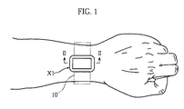
図1に示したグルコース濃度測定装置X1は、腕などの皮膚に密着させて使用するものであり、グルコース濃度測定を連続的に行い、あるいは複数回のグルコース濃度測定を継続して行えるように構成されている。図2および図3に示したように、グルコース濃度測定装置X1は、筐体1およびグルコースセンサ2を有している。 The glucose concentration measuring device X1 shown in FIG. 1 is used in close contact with the skin such as an arm, and is configured to continuously measure glucose concentration or continuously measure glucose concentration a plurality of times. Has been. As shown in FIGS. 2 and 3, the glucose concentration measuring device X <b> 1 has a
筐体1は、たとえばバンド10(図1参照)を用いて腕などに固定されるものであり、凹部11、表示部12、一対のコネクタピン13a,13bおよび図外の制御回路を有している。凹部11は、グルコースセンサ2を着脱自在に収容するためのものである。表示部12は、主として測定結果を表示するためのものであり、LCDなどにより構成されている。コネクタピン13a,13bは、後述するグルコースセンサ2の作用極32または対極33に接触させるためのものである。コネクタピン13a,13bは、グルコースセンサ2の作用極32と対極33との間に電圧を印加するために、あるいは電圧印加時の応答電流を測定するために利用されるものである。 The
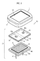
グルコースセンサ2は、互いに接合されたセンサ本体3および試料採取部材4を備えており、これらを一体として筐体1に対して着脱自在とされている。このグルコースセンサ2は、たとえば使い捨てとして構成されている。もちろん、センサ本体3と試料採取部材4とを個別に筐体1に対して着脱自在とし、センサ本体3および試料採取部材4を個別に交換するように構成することもできる。 The
センサ本体3は、絶縁基板30の下面31に作用極32および対極33を形成したものである。絶縁基板30には、一対の貫通孔30a,30bが設けられている。貫通孔30aは作用極32を露出させるためのものであり、貫通孔30bは対極33を露出させるためのものである。すなわち、センサ本体3は、グルコースセンサ2を筐体1の凹部11に収容させた状態では、コネクタピン13aが作用極32に接触し、コネクタピン13bが対極33に接触し得るように構成されている。 The
作用極32は、導体成分およびグルコースデヒドロゲナーゼ(GDH)を含んでおり、グルタルアルデヒドなどの架橋剤によって絶縁基板30に固定されている。 The working
導体成分は、たとえばカーボン粉末により構成されており、その含有量は、たとえば5〜100mgとされる。もちろん、導体成分としては、カーボン以外の導体粉末、あるいは多孔質に形成された導体(たとえば導体粉末の焼結体)を使用することもできる。 The conductor component is made of, for example, carbon powder, and the content thereof is, for example, 5 to 100 mg. Of course, as the conductor component, a conductor powder other than carbon or a conductor formed porous (for example, a sintered body of conductor powder) can be used.
GDHとしては、グルコース脱水素活性を有する触媒活性サブユニットおよび電子伝達サブユニットが互いに結合したタンパク質複合体が使用される。 As GDH, a protein complex in which a catalytically active subunit having glucose dehydrogenation activity and an electron transfer subunit are bound to each other is used.
触媒活性サブユニットは、試料中のグルコースから電子を取り出し、この電子を電子伝達サブユニットに供与する役割を果たすものであり、補酵素としてフラビンアデニンジヌクレオチド(FAD)を有するものが使用される。したがって、電子伝達サブユニットに対しては、還元型FADを介して、触媒活性サブユニットからの電子が供与される。 The catalytically active subunit plays a role of taking out electrons from glucose in the sample and donating the electrons to the electron transfer subunit, and one having flavin adenine dinucleotide (FAD) as a coenzyme is used. Therefore, electrons from the catalytically active subunit are donated to the electron transfer subunit via the reduced FAD.
触媒活性サブユニットの含有量は、たとえば活性に換算して5〜100Uに相当する量とされる。ここで、酵素1単位(1U)は、標準検定条件(pH6.0、37℃)の下でDCIP(2,6−ジクロロフェノールインドフェノール)の還元にもとづく退色を、DCIPの吸収波長である600nmにおいて経時的に計測したときに、1分ごとに1μMグルコースを酸化する量(モル吸光係数は4.76×1000μM/cm)として定義される。 The content of the catalytically active subunit is, for example, an amount corresponding to 5 to 100 U in terms of activity. Here, 1 unit (1 U) of enzyme is the absorption wavelength of DCIP, which is 600 nm, based on the reduction of DCIP (2,6-dichlorophenolindophenol) under standard assay conditions (pH 6.0, 37 ° C.). Is measured as the amount that oxidizes 1 μM glucose per minute when measured over time (molar extinction coefficient is 4.76 × 1000 μM / cm).
一方、電子伝達サブユニットは、触媒活性サブユニットから授与された電子を、導体成分に供与する役割を果たすものである。電子伝達サブユニットとしては、たとえばチトクロムCが使用される。 On the other hand, the electron transfer subunit plays a role of donating electrons given from the catalytically active subunit to the conductor component. For example, cytochrome C is used as the electron transfer subunit.
触媒活性サブユニットおよび電子伝達サブユニットとしては、ブルクホルデリア属に属する微生物、たとえばKS1株に由来するタンパク質複合体を使用するのが好ましい。KS1株由来のGDHは、触媒活性サブユニットとして機能するαサブユニット(還元条件下でのSDS−ポリアクリルアミドゲル電気泳動における分子量が約60kDa)、電子伝達タンパク質であるβサブユニット(還元条件下でのSDS−ポリアクリルアミドゲル電気泳動における分子量が約43kDa)、およびγサブユニット(還元条件下でのSDS−ポリアクリルアミドゲル電気泳動における分子量が約14kDa)が結合した3量体として、あるいはαサブユニットとβサブユニットからなる2量体として生成される。もちろん、GDHとしては、αサブユニット、βサブユニットおよびγサブユニットをコードするDNAを移入した形質転換体によって生成させたタンパク質複合体を使用することもできる。 As the catalytic activity subunit and the electron transfer subunit, it is preferable to use a microorganism belonging to the genus Burkholderia, for example, a protein complex derived from KS1 strain. The GDH derived from the KS1 strain has an α subunit that functions as a catalytically active subunit (molecular weight in SDS-polyacrylamide gel electrophoresis under reducing conditions is approximately 60 kDa), a β subunit that is an electron transfer protein (under reducing conditions) As a trimer with a molecular weight in SDS-polyacrylamide gel electrophoresis of about 43 kDa) and a γ subunit (molecular weight in SDS-polyacrylamide gel electrophoresis under reducing conditions of about 14 kDa) or α subunit And β-subunit. Of course, as GDH, a protein complex produced by a transformant into which DNAs encoding an α subunit, β subunit and γ subunit have been transferred can also be used.
上記微生物あるいは形質転換体によって目的とするGDHを取得する場合には、それらのサブユニット(タンパク質)を個別に精製し、あるいはそれらを個別に準備する必要がなく、さらには電子伝達物質をGDHとは別に作用極32に含有させる必要がないため、それらの点においてコスト的に有利である。 When the target GDH is obtained by the microorganism or the transformant, it is not necessary to individually purify the subunits (proteins) or to prepare them individually, and further, the electron transfer substance is referred to as GDH. In addition, since it is not necessary to be contained in the working
対極33は、たとえばカーボンペーストをスクリーン印刷により形成することができる。もちろん、対極33は、カーボン以外の導体成分により形成することができ、スクリーン印刷以外の手法により形成することもできる。 The
試料採取部材4は、皮膚から試料(血液または間質液)を採取するためのものであり、絶縁基板40、穿刺針41、および液吸収体42を有している。 The sample collection member 4 is for collecting a sample (blood or interstitial fluid) from the skin, and has an insulating
絶縁基板40は、穿刺針41および液吸収体42を固定するためのものであり、その下面40aには、両面に接着性を有する粘着テープ43が貼着されている。これにより、絶縁基板40ひいてはグルコースセンサ2を皮膚Skに密着して固定することができる。穿刺針41は、皮膚に突き刺して試料を採取するための部分であり、中空状に形成されている。この穿刺針41は、絶縁基板40を貫通し、絶縁基板40の上面において開放している。液吸収体42は、穿刺針41によって採取された試料を保持するためのものであり、穿刺針41の上端を覆うように配置されている。この液吸収体42は、筐体1にグルコースセンサ2を収容した状態では、センサ本体3の作用極32および対極33に接触する。液吸収体42は、たとえば多孔質体として形成されている。多孔質体としては、たとえば織布、不織布、編布、あるいは発泡体を使用することができる。なお、液吸収体42に代えて、採取した試料を保持するための空間を設けてもよい。 The insulating
グルコース濃度測定装置X1は、上述の要素に加えて、図4に示したように電圧印加部14、電流値測定部15、演算部16および制御部17を備えている。 In addition to the above-described elements, the glucose concentration measurement device X1 includes a
電圧印加部14は、作用極32および対極33に電圧を印加するためのものであり、図面上には表れていないが、コネクタピン13a,13b(図2参照)に導通接続されている。 The
電流値測定部15は、作用極32と対極33との間に電圧を印加したときの応答電流値を測定するためのものである。 The current
演算部16は、電流値測定部15において測定された応答電流値に基づいて、試料中のグルコース濃度を演算するためのものである。 The
制御部17は、各部12,14〜16の動作を制御するためのものである。より具体的には、電流値測定部15を制御して応答電流値を測定するタイミングを制御し、演算部16を制御してグルコース濃度を演算させ、あるいは表示部12を制御して表示部12での表示内容を制御する。 The
図2によく表れているように、グルコース濃度測定装置X1では、グルコースセンサ2を皮膚Skに固定した上で、筐体1によってグルコースセンサ2を覆うことにより、グルコース濃度測定を連続的に行い、あるいは複数回のグルコース濃度測定を継続的に行うことができる。グルコースセンサ2を皮膚Skに固定した場合には、試料採取部材4の穿刺針41が皮膚Skに突き刺さっている。穿刺針41が中空に形成されていることから、液吸収体42には、穿刺針41を介して試料が供給される。この状態では、液吸収体42と皮下組織との間が液絡しているために、皮下組織におけるグルコース濃度が変化した場合には、皮下組織でのグルコース濃度と平衡を保つために、液吸収体42でのグルコース濃度が変化する。すなわち、液吸収体42でのグルコース濃度は、皮下組織におけるグルコース濃度を反映したものとなる。 As shown well in FIG. 2, in the glucose concentration measuring device X1, the
一方、液吸収体42は、作用極32と接触している。そのため、試料中のグルコースからは、作用極32の触媒活性サブユニットによって電子が取り出される。この電子は、電子伝達サブユニットに供与される。作用極32と対極33との間には、図4に示した電圧印加部14を介して継続的に電位差が与えられている。これは、電子伝達サブユニットに必要以上に電子が蓄積されるのを抑制し、リアルタイムで応答電流値を測定するためである。電子伝達サブユニットに供与された電子は、作用極32と対極33との間に電位差が与えられることによって、導体成分に供与される。作用極32は、コネクタピン13aを介して電流値測定部15に接続されているため、電流値測定部15においては、電子伝達サブユニットから供与された電子の量が応答電流値として測定される。 On the other hand, the
図4に示した制御部17は、連続的または一定時間毎(たとえば5分〜2時間毎)に応答電流値をサンプリングするとともに、演算部16に対して、サンプリングされた応答電流値に基づいてグルコース濃度を連続的または一定時間毎に演算させる。演算部16においては、予め調べられた検量線に対して、測定された応答電流値を当てはめることによりグルコース濃度が演算される。グルコース濃度の演算が終了した場合には、制御部17は、表示部12に対して演算部16における濃度演算結果を表示させる。 The
グルコースセンサ2では、作用極32において、酵素として、触媒活性サブユニットに対して電子伝達サブユニットが結合(サブユニット化)したGDHが含有をさせられている。このため、作用極32においては、触媒活性を有するタンパク質(触媒活性サブユニット)の周りに、作用極32に対して電子を伝達する機能を有するタンパク質(電子伝達サブユニット)が均一に存在する環境が作り出されている。すなわち、触媒活性を有するタンパク質(触媒活性サブユニット)に対して、分子数で等量の電子伝達タンパク質(電子伝達サブユニット)が密着した状態で存在する。その結果、グルコースセンサ2では、触媒活性タンパク質と触媒電子伝達タンパク質との間の反応速度(電子授受速度)を大きくして応答感度を高めるとともに、安定した応答電流の測定を行うことができる。 In the
次に、本発明の第2の実施の形態について、図5および図6を参照して説明する。 Next, a second embodiment of the present invention will be described with reference to FIGS.
図5および図6に示したグルコース濃度測定装置X2は、先に説明した本発明の第1の実施の形態に係るグルコース濃度測定装置X1と同様に、バンドや粘着テープを利用して腕などの皮膚Skに密着させて使用するものである(図1参照)。このグルコース濃度測定装置X2は、グルコース濃度測定を連続的に行い、あるいは複数回のグルコース濃度の測定を継続して行うことが可能なように構成されており、グルコースセンサ5および筐体6を有している。 The glucose concentration measuring device X2 shown in FIG. 5 and FIG. 6 is similar to the glucose concentration measuring device X1 according to the first embodiment of the present invention described above, such as an arm using a band or an adhesive tape. It is used in close contact with the skin Sk (see FIG. 1). This glucose concentration measuring device X2 is configured to continuously measure glucose concentration or continuously measure glucose concentration a plurality of times, and has a
グルコースセンサ5は、筐体6に対して着脱自在とされており、たとえば使い捨て可能なように構成されている。このグルコースセンサ5は、絶縁基板50上に作用極51および対極52が形成された形態を有している。絶縁基板50は、皮膚Skに突き刺すための細幅部分50aを有するとともに、ポリイミド樹脂などにより可撓性を有するものとして形成されている。作用極51および対極52は、端子部51a,52aを有している。作用極51および対極52は、先に説明したグルコースセンサ2の作用極32および対極33(図3参照)と同様にして形成されている。 The
筐体6は、第1および第2部材61,62を有しており、これらの部材61,62の間には、空間63が形成されている。空間63は、グルコースセンサ5を保持するためのものである。 The housing 6 has first and
第1部材61には、表示部64および一対のコネクタピン65a,65bが設けられている。表示部64は、各種の情報を表示するためのものであり、たとえばLCDにより構成されている。コネクタピン65a,65bは、図外の制御回路に繋がっており、空間63にグルコースセンサ5を保持した状態においては、作用極51および対極52の端子部51a,52aに接触するように構成されている。この状態においては、コネクタピン65a,65bを利用して作用極51および対極52の間への電圧の印加が可能であり、また電圧印加状態においては電流値の測定が可能となる。一方、第2部材62には、絶縁基板50の細幅部分50aを外部に突出させるための開口部66が形成されている。 The
このようなグルコース濃度測定装置X2では、筐体6にグルコースセンサ5を保持させた状態において、絶縁基板50の細幅部分50aを皮膚Skに突き刺すことにより、連続的にグルコース濃度測定を行い、あるいは複数回のグルコース濃度測定を継続的に行うことが可能となる。 In such a glucose concentration measuring device X2, in the state where the
皮膚Skに絶縁基板50の細幅部分50aを突き刺した状態においては、作用極51において血液または間質液のグルコースから電子が取り出される。この電子は、電子伝達サブユニットに供与される。電子伝達サブユニットに供与された電子は、作用極51および対極52の間に電位差を与えることにより作用極51の導体成分に供与される。このときに供与された電子の量は、コネクタピン65a,65bを介して応答電流値として測定することができる。グルコース濃度測定装置X2においては、連続的または一定時間毎(たとえば5分〜2時間毎)に応答電流値をサンプリングするとともに、サンプリングされた応答電流値に基づいてグルコース濃度が連続的または一定時間毎に演算される。演算結果は、表示部64において表示される。 In a state where the
グルコースセンサ5においても、作用極51が触媒活性サブユニットおよび電子伝達サブユニットが結合したタンパク質複合体を含んだものとなっている。そのため、グルコースセンサ5が人体に対して悪影響を与えることはなく、また安定した応答電流の測定をコスト的に有利に行うことができる。 Also in the
本実施例においては、酵素電極の応答特性について、バッチ式の反応槽を用いて検討した。 In this example, response characteristics of the enzyme electrode were examined using a batch-type reaction tank.
酵素電極は、プラスチックチューブ(直径5mm、長さ30mm)の内部に、酵素とカーボン粉末を固定化した構成とした。酵素およびカーボン粉末の固定化は、酵素とカーボンペース(20mg)の混合物をプラスチックチューブに充填した後に、プラスチックチューブの内部に、架橋剤としての1%グルタルアルデヒドを含む100mMのリン酸ナトリウム緩衝液(pH7.0)を30分間含浸させることにより行った。架橋剤における過剰なアルデヒド基は、10mMのTris−HCl中で20分間処理することにより不活性化した。酵素電極は、使用する前に、100mMのリン酸ナトリウム緩衝液(pH7.0)に浸漬して平衡化しておいた。酵素としては、KS1株由来のαサブユニット(触媒活性サブユニット)、βサブユニット(電子伝達サブユニット)およびγサブユニットからなるCyGDH(92.1U/mg)、またはKS1株由来のαサブユニット(触媒活性サブユニット)およびγサブユニットからなるαGDH(21.3U/mg)を使用し、2種類の酵素電極を作成した。酵素電極においては、酵素の含有量を10Uに相当する量とした。 The enzyme electrode had a structure in which an enzyme and carbon powder were fixed inside a plastic tube (
応答特性は、濃度の異なる複数のグルコース溶液について、応答電流を測定した結果に基づいて検討した。応答電流値は、目的濃度に調整されたグルコース溶液を保持した反応槽に対して、酵素電極、参照電極および対極を浸漬するとともに、酵素電極と対極との間に電圧を印加し、参照電極を基準電極として測定した。グルコース溶液は、グルコースを100mMのリン酸ナトリウム緩衝液(pH7.0)に溶解させることにより作成した。グルコース溶液の濃度は、0mM、0.5mM、1.0mM、1.5mM、2.0mM、2.5mM、8mM、12mM、21mM、30mMおよび47mMに設定した。参照電極としてはAg/AgCl電極を用い、対極としてはPt電極を用いた。印加電圧値は+400mVとし、応答電流値の測定は、反応槽の温度を25℃または37℃に維持して行った。応答電流値の測定結果については、図8に示した。 The response characteristic was examined based on the result of measuring the response current for a plurality of glucose solutions having different concentrations. The response current value is determined by immersing the enzyme electrode, the reference electrode and the counter electrode in a reaction vessel holding a glucose solution adjusted to the target concentration, and applying a voltage between the enzyme electrode and the counter electrode. Measured as a reference electrode. The glucose solution was prepared by dissolving glucose in 100 mM sodium phosphate buffer (pH 7.0). The concentration of the glucose solution was set to 0 mM, 0.5 mM, 1.0 mM, 1.5 mM, 2.0 mM, 2.5 mM, 8 mM, 12 mM, 21 mM, 30 mM and 47 mM. An Ag / AgCl electrode was used as the reference electrode, and a Pt electrode was used as the counter electrode. The applied voltage value was +400 mV, and the response current value was measured while maintaining the reaction vessel temperature at 25 ° C. or 37 ° C. The measurement result of the response current value is shown in FIG.
図8から分かるように、βサブユニット(電子伝達サブユニット)を有しないαGDHを用いた酵素電極では、グルコース濃度の増加に伴う応答電流値の増加量が小さく、作用極における導体成分とαサブユニットとの間で、適切な電子伝達が行われていないことが伺える。これに対して、βサブユニットを有するCyGDHを用いた酵素電極では、グルコース濃度の増加に伴う応答電流値の増加量が大きく、良好な応答特性が得られている。すなわち、βサブユニットをαサブユニットに結合(サブユニット化)させることにより、作用極における導体成分とαサブユニットとの間で、適切な電子伝達が行われていることが伺える。このような傾向は、測定温度を25℃および37℃に設定した場合のいずれにおいても伺える。したがって、電子伝達タンパク質が結合したGDHを用いた酵素電極では、金属錯体などの電子伝達物質を用いることなく、電極法において、グルコース濃度の測定を行うことができる。 As can be seen from FIG. 8, in the enzyme electrode using αGDH having no β subunit (electron transfer subunit), the increase in the response current value accompanying the increase in glucose concentration is small, and the conductor component and α subunit in the working electrode are small. It can be seen that there is no proper electronic communication with the unit. On the other hand, in an enzyme electrode using CyGDH having a β subunit, the amount of increase in the response current value accompanying an increase in glucose concentration is large, and good response characteristics are obtained. That is, it can be seen that appropriate electron transfer is performed between the conductor component in the working electrode and the α subunit by coupling (subunit) the β subunit to the α subunit. Such a tendency can be observed in both cases where the measurement temperature is set to 25 ° C. and 37 ° C. Therefore, in an enzyme electrode using GDH to which an electron transfer protein is bound, the glucose concentration can be measured by an electrode method without using an electron transfer substance such as a metal complex.
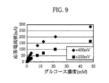
本実施例においては、印加電圧が酵素電極の応答特性に与える影響について、バッチ式の反応槽を用いて検討した。酵素電極は、基本的には実施例1と同様にして作成した。ただし、酵素としては、比活性56.5U/mgであるCyGDHを用い、また酵素電極における酵素の含有量を50Uに相当する量とした。応答特性については、目的濃度のグルコース溶液を37℃に維持し、印加電圧を+400mVおよび+250mVとした場合のそれぞれについて、応答電流値を測定した結果に基づいて検討した。グルコース溶液の濃度は、0mM、0.5mM、1.0mM、1.5mM、2.0mM、2.5mM、8mM、12mM、21mM、および47mMに設定した。応答電流値の測定結果については、図9に示した。 In this example, the influence of the applied voltage on the response characteristics of the enzyme electrode was examined using a batch-type reaction vessel. The enzyme electrode was basically produced in the same manner as in Example 1. However, as the enzyme, CyGDH having a specific activity of 56.5 U / mg was used, and the enzyme content in the enzyme electrode was set to an amount corresponding to 50 U. The response characteristics were examined based on the results of measuring the response current values when the target concentration of the glucose solution was maintained at 37 ° C. and the applied voltages were +400 mV and +250 mV. The concentration of the glucose solution was set to 0 mM, 0.5 mM, 1.0 mM, 1.5 mM, 2.0 mM, 2.5 mM, 8 mM, 12 mM, 21 mM, and 47 mM. The measurement result of the response current value is shown in FIG.
図9から分かるように、印加電圧値が+250mVの場合には、印加電圧値が+400mVの場合に比べて応答電流値が小さくなっているものの、印加電圧値が+400mVおよび+250mVのいずれの場合においても適切に応答電流値を測定できるといえる。したがって、電子伝達タンパク質が結合したGDHを用いた場合には、印加電圧値が比較的に小さくても適切に応答電流値を測定し、グルコース濃度を測定することができる。この結果は、連続的あるいは継続的な血糖値モニターを行う場合のように、連続的に電圧を印加する必要がある場合に、あるいは連続的または継続的な血糖値モニターを行うためのグルコース濃度測定装置を、電池によって駆動する場合に、優位に作用する。 As can be seen from FIG. 9, when the applied voltage value is +250 mV, the response current value is smaller than when the applied voltage value is +400 mV, but in both cases where the applied voltage value is +400 mV and +250 mV. It can be said that the response current value can be measured appropriately. Therefore, when GDH to which an electron transfer protein is bound is used, the response current value can be appropriately measured and the glucose concentration can be measured even if the applied voltage value is relatively small. This result is measured when the voltage needs to be applied continuously, such as when performing continuous or continuous blood glucose monitoring, or when measuring glucose concentration for continuous or continuous blood glucose monitoring. This is advantageous when the device is driven by a battery.
本実施例においては、酵素電極を用いての連続的なグルコース濃度のモニターの可能性について、フローセルを用いて検討した。具体的には、(1)72時間の連続モニター試験、(2)作成初期(未使用)の酵素電極と、72時間の連続モニターに使用後の酵素電極の応答特性について検討した。 In this example, the possibility of continuous glucose concentration monitoring using an enzyme electrode was examined using a flow cell. Specifically, the response characteristics of (1) 72-hour continuous monitoring test, (2) initial (unused) enzyme electrode, and 72-hour continuous monitoring were used.
(1)連続モニター試験
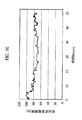
連続モニター試験は、図7に概略構成を示した測定システム7を用いて行った。この測定システム7は、反応セル70に、酵素電極71、参照電極72および対極73を保持させ、反応セル70の内部にグルコース溶液を供給したときに、これらの電極71〜73がグルコース溶液に接触するように構成されたものである。各電極71〜73は、ポテンシオスタット74に接続されている。反応セル70には、流路75が規定されており、反応セル70は、グルコース溶液を連続的に供給・排出可能なフローセルとして構成されている。反応セル70には、目的とする濃度のグルコース溶液が保持された容器76から、ポンプ77の動力を介してグルコース溶液が連続的に供給されるように構成されている。測定システム7では、酵素電極71として実施例2と同様にして作成したもの、参照電極72としてフローセル用のAg/AgCl電極、対極73としてはステンレスチューブが用いられている。(1) Continuous monitor test The continuous monitor test was performed using the measurement system 7 whose schematic configuration is shown in FIG. In this measurement system 7, when the
応答電流値は、酵素電極71と対極73との間に電圧を印加するとともに、参照電極72を基準電極として測定した。印加電圧値は+250mVとした。応答電流値の測定は、反応セル70に対して5mMのグルコース溶液(pH7.0)を0.1ml/minの流速で連続的に供給するとともに、グルコース溶液の温度を37℃に維持した状態において、連続的に測定した。応答電流値の経時変化については、図10に示した。図10においては、縦軸の応答電流を、測定時間が「0」のときの値を100とした相対値として示してある。 The response current value was measured by applying a voltage between the
(2)使用前後の酵素電極の応答特性
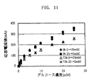
使用前(0h)および使用後(72h)の酵素電極の応答特性は、図7に示した測定システム7を用いて、目的濃度のグルコース溶液を37℃に維持した状態において0.5ml/minの流速で供給し、印加電圧を+250mVとして測定した応答電流値に基づいて検討した。グルコース溶液は、0mM、0.5mM、1.0mM、2.5mM、10.0mM、15.0mM、20.0mMおよび25mMの順に段階的上昇させた後、先とは逆に段階的に濃度を減少させて供給した。応答電流値の測定結果については、図11に示した。(2) Response characteristics of enzyme electrode before and after use The response characteristics of the enzyme electrode before use (0 h) and after use (72 h) were measured using a measurement system 7 shown in FIG. In this state, the sample was supplied at a flow rate of 0.5 ml / min and examined based on the response current value measured at an applied voltage of +250 mV. The glucose solution is gradually increased in the order of 0 mM, 0.5 mM, 1.0 mM, 2.5 mM, 10.0 mM, 15.0 mM, 20.0 mM and 25 mM, and then the concentration is gradually increased. Reduced supply. The measurement result of the response current value is shown in FIG.
図10から分かるように、72時間の連続モニター試験においては、応答電流値が経時的に低下しているものの、72時間後においても一定量の応答電流値が測定されている。一方、図11から分かるように、72時間の連続モニターに使用した後の酵素電極は、使用前の酵素電極に比べて応答特性が悪くなっているが、グルコース濃度を測定するのに十分な応答特性を有している。これらの結果は、電子伝達タンパク質が結合したGDHを用いた酵素電極においては、72時間の連続モニター試験後においてもGDHが十分な残存活性を有しており、たとえばCyGDHを用いた酵素電極を用いて連続モニターが可能であることを示唆している。 As can be seen from FIG. 10, in the continuous monitoring test for 72 hours, the response current value decreased with time, but a constant amount of response current value was measured after 72 hours. On the other hand, as can be seen from FIG. 11, the enzyme electrode after being used for continuous monitoring for 72 hours has a worse response characteristic than the enzyme electrode before being used, but it has a response sufficient to measure the glucose concentration. It has characteristics. These results show that in the enzyme electrode using GDH to which the electron transfer protein is bound, GDH has a sufficient residual activity even after 72 hours of continuous monitoring test. For example, the enzyme electrode using CyGDH is used. This suggests that continuous monitoring is possible.
すなわち、酵素電極での応答電流値の経時的劣化を予め調べておいた上で、経時劣化の予測に基づいて、測定値や演算値を補正すれば、連続モニターが可能となる。また、酵素電極を改良して経時劣化を抑制するようにすれば、連続モニターが可能となる。さらには、酵素電極の経時的劣化に伴う応答電流値の減少分を、印加電圧を経時的に増加させて応答電流値を強制的に増大させて相殺すること、すなわち図11に示した応答電流値が一定値で推移するように印加電圧を制御することにより、連続モニターが可能となる。 In other words, continuous monitoring is possible by preliminarily examining the deterioration over time of the response current value at the enzyme electrode and correcting the measured value and the calculated value based on the prediction of the deterioration over time. In addition, continuous monitoring is possible by improving the enzyme electrode to suppress deterioration over time. Furthermore, the decrease in the response current value due to the deterioration of the enzyme electrode over time is canceled by increasing the applied voltage with time to forcibly increase the response current value, that is, the response current shown in FIG. Continuous monitoring is possible by controlling the applied voltage so that the value changes at a constant value.
連続モニター試験からは、次の知見も得られる。すなわち、最初の18時間程度の間の応答電流値の減少量が大きく、その後の応答電流値は比較的に安定している。したがって、酵素電極(グルコースセンサ)をある程度意図的に劣化させた後に実際のグルコース濃度測定を行うといった使用方法も考えられる。 The following knowledge is also obtained from the continuous monitoring test. That is, the amount of decrease in the response current value during the first approximately 18 hours is large, and the response current value thereafter is relatively stable. Therefore, a method of use is also conceivable in which an actual glucose concentration measurement is performed after intentionally degrading the enzyme electrode (glucose sensor) to some extent.
また、図11から分かるように、使用前(0h)および使用後(72h)の酵素電極(グルコースセンサ)は、グルコース濃度を上昇させる過程(0mM→25mM)とグルコース濃度を減少させる過程(25mM→0mM)との間に良好な相関関係が見受けられる。このことは、血糖値を連続的にモニターする場合のように、グルコース濃度が経時的に変動する環境下において、適切にグルコース濃度を測定できることを意味している。 Further, as can be seen from FIG. 11, the enzyme electrode (glucose sensor) before use (0h) and after use (72h) has a process of increasing the glucose concentration (0 mM → 25 mM) and a process of decreasing the glucose concentration (25 mM → A good correlation is found with 0 mM). This means that the glucose concentration can be measured appropriately in an environment where the glucose concentration varies with time, as in the case of continuously monitoring the blood glucose level.
Claims (20)
上記グルコース脱水素酵素は、フラビンアデニンジヌクレオチドが補酵素として結合し、かつグルコース脱水素活性を有する触媒活性サブユニットと、上記触媒活性サブユニットから供与された電子を、上記導体成分に授与するための電子伝達サブユニットと、を含むタンパク質複合体であることを特徴とする、グルコースセンサ。It has an electrode with glucose dehydrogenase immobilized on the conductor component,
In the glucose dehydrogenase, flavin adenine dinucleotide is bound as a coenzyme, and a catalytically active subunit having glucose dehydrogenating activity and an electron donated from the catalytically active subunit are imparted to the conductor component. A glucose sensor, comprising: a protein complex comprising:
上記採取要素によって採取した血液または間質液を、上記電極に接触させることができるように構成されている、請求項6に記載のグルコースセンサ。Further comprising a collection element for collecting blood or interstitial fluid from the subcutaneous tissue;
The glucose sensor according to claim 6, wherein blood or interstitial fluid collected by the collection element can be brought into contact with the electrode.
上記液溜部に滞留させた血液または間質液を上記電極に接触させるように構成されている、請求項7に記載のグルコースセンサ。The collection element includes a hollow puncture needle for piercing the skin, and a liquid reservoir for retaining blood or interstitial fluid collected via the puncture needle,
The glucose sensor according to claim 7, wherein blood or interstitial fluid retained in the liquid reservoir is configured to contact the electrode.
グルコース脱水素酵素を導体成分に固定化した電極を有するグルコースセンサと、
上記血液または間質液と上記電極との間の電子授受量に相関した応答量を測定するための測定部と、
上記測定部での測定結果に基づいてグルコース濃度を演算する演算部と、
上記演算部においてグルコース濃度を演算するタイミングを制御する制御部と、
を備えており、かつ、
上記グルコース脱水素酵素は、フラビンアデニンジヌクレオチドが補酵素として結合し、かつグルコース脱水素活性を有する触媒活性サブユニットと、上記触媒活性サブユニットから供与された電子を、上記導体成分に授与するための電子伝達サブユニットと、を含むタンパク質複合体であることを特徴とする、グルコース濃度測定装置。A glucose concentration measuring device configured to be capable of continuously measuring glucose concentration or continuously measuring glucose concentration a plurality of times based on blood or interstitial fluid collected from subcutaneous tissue. ,
A glucose sensor having an electrode in which glucose dehydrogenase is immobilized on a conductor component;
A measurement unit for measuring a response amount correlated with an electron exchange amount between the blood or interstitial fluid and the electrode;
A calculation unit for calculating a glucose concentration based on the measurement result in the measurement unit;
A control unit for controlling the timing of calculating the glucose concentration in the calculation unit;
And
In the glucose dehydrogenase, flavin adenine dinucleotide is bound as a coenzyme, and a catalytically active subunit having glucose dehydrogenating activity and an electron donated from the catalytically active subunit are imparted to the conductor component. And an electron transfer subunit. A glucose concentration measuring apparatus, comprising:
上記採取要素によって採取した血液または間質液を、上記電極に接触させることができるように構成されている、請求項12に記載のグルコース濃度測定装置。Further comprising a collection element for collecting blood or interstitial fluid from the subcutaneous tissue;
The glucose concentration measurement apparatus according to claim 12, wherein blood or interstitial fluid collected by the collection element can be brought into contact with the electrode.
上記液溜部に滞留させた血液または間質液を上記電極に接触させるように構成されている、請求項16に記載のグルコース濃度測定装置。The collection element includes a hollow puncture needle for piercing the skin, and a liquid reservoir for retaining blood or interstitial fluid collected via the puncture needle,
The glucose concentration measuring device according to claim 16, wherein blood or interstitial fluid retained in the liquid reservoir is configured to contact the electrode.
Applications Claiming Priority (3)
| Application Number | Priority Date | Filing Date | Title |
|---|---|---|---|
| JP2003310019 | 2003-09-02 | ||
| JP2003310019 | 2003-09-02 | ||
| PCT/JP2004/012625 WO2005023111A1 (en) | 2003-09-02 | 2004-09-01 | Glucose sensor and glucose level measuring apparatus |
Publications (2)
| Publication Number | Publication Date |
|---|---|
| JPWO2005023111A1 JPWO2005023111A1 (en) | 2007-11-01 |
| JP4359595B2 true JP4359595B2 (en) | 2009-11-04 |
Family
ID=34269631
Family Applications (1)
| Application Number | Title | Priority Date | Filing Date |
|---|---|---|---|
| JP2005513645A Active JP4359595B2 (en) | 2003-09-02 | 2004-09-01 | Glucose sensor and glucose concentration measuring device |
Country Status (5)
| Country | Link |
|---|---|
| US (2) | US7497940B2 (en) |
| EP (1) | EP1661516B1 (en) |
| JP (1) | JP4359595B2 (en) |
| CN (2) | CN101558992B (en) |
| WO (1) | WO2005023111A1 (en) |
Cited By (3)
| Publication number | Priority date | Publication date | Assignee | Title |
|---|---|---|---|---|
| JP2016530970A (en) * | 2012-08-06 | 2016-10-06 | ヴェリリー ライフ サイエンシズ エルエルシー | Contact lens with two-electrode electrochemical sensor |
| JP2016537177A (en) * | 2014-10-22 | 2016-12-01 | 深▲せん▼市光聚通訊技術開発有限公司Shenzhen Waveguider Optical Telecom Technology Inc. | Continuous blood glucose measurement system and measurement terminal |
| JP2017500994A (en) * | 2014-10-27 | 2017-01-12 | 深▲せん▼市光聚通訊技術開発有限公司Shenzhen Waveguider Optical Telecom Technology Inc. | Continuous blood glucose collection device and main body |
Families Citing this family (60)
| Publication number | Priority date | Publication date | Assignee | Title |
|---|---|---|---|---|
| JP4359595B2 (en) * | 2003-09-02 | 2009-11-04 | 広司 早出 | Glucose sensor and glucose concentration measuring device |
| CN100367906C (en) * | 2004-12-08 | 2008-02-13 | 圣美迪诺医疗科技(湖州)有限公司 | Endermic implantating biological sensors |
| US10226207B2 (en) | 2004-12-29 | 2019-03-12 | Abbott Diabetes Care Inc. | Sensor inserter having introducer |
| US7697967B2 (en) | 2005-12-28 | 2010-04-13 | Abbott Diabetes Care Inc. | Method and apparatus for providing analyte sensor insertion |
| JP5021183B2 (en) | 2005-05-20 | 2012-09-05 | アークレイ株式会社 | Protein immobilization membrane, immobilization method, and biosensor |
| EP1733676B1 (en) * | 2005-06-17 | 2012-08-01 | F. Hoffmann-La Roche AG | Sensor system, arrangement and method for monitoring a compound, in particular glucose in body tissue. |
| CN101365374B (en) | 2005-08-31 | 2011-11-16 | 弗吉尼亚大学专利基金委员会 | Improving accuracy of continuous glucose sensors |
| JP2007105316A (en) * | 2005-10-14 | 2007-04-26 | Konica Minolta Sensing Inc | Bioinformation measuring instrument |
| US11298058B2 (en) | 2005-12-28 | 2022-04-12 | Abbott Diabetes Care Inc. | Method and apparatus for providing analyte sensor insertion |
| US8219173B2 (en) | 2008-09-30 | 2012-07-10 | Abbott Diabetes Care Inc. | Optimizing analyte sensor calibration |
| US7653425B2 (en) | 2006-08-09 | 2010-01-26 | Abbott Diabetes Care Inc. | Method and system for providing calibration of an analyte sensor in an analyte monitoring system |
| US9700252B2 (en) | 2006-06-19 | 2017-07-11 | Roche Diabetes Care, Inc. | Amperometric sensor and method for its manufacturing |
| CN101473225B (en) | 2006-06-19 | 2016-05-11 | 霍夫曼-拉罗奇有限公司 | Amperometric sensor and manufacture method thereof |
| US9119582B2 (en) | 2006-06-30 | 2015-09-01 | Abbott Diabetes Care, Inc. | Integrated analyte sensor and infusion device and methods therefor |
| JP5118640B2 (en) * | 2006-07-12 | 2013-01-16 | アークレイ株式会社 | Enzyme electrode |
| CN101802597B (en) * | 2007-09-18 | 2013-08-21 | 究极酵素国际股份有限公司 | Enzyme electrode |
| ES2386231T3 (en) | 2007-11-30 | 2012-08-14 | Universiteit Maastricht | Diagnostic and therapeutic tool for diseases that alter vascular function |
| JP5088148B2 (en) * | 2008-01-16 | 2012-12-05 | Tdk株式会社 | Method for measuring metabolite concentration and electrochemical sensor used therefor |
| US20100198033A1 (en) * | 2009-02-05 | 2010-08-05 | Peter Krulevitch | Flexible indwelling biosensor, flexible indwelling biosensor insertion device, and related methods |
| CN102405018B (en) | 2009-03-02 | 2014-11-19 | 第七感生物系统有限公司 | Techniques and devices associated with blood sampling |
| US9033898B2 (en) | 2010-06-23 | 2015-05-19 | Seventh Sense Biosystems, Inc. | Sampling devices and methods involving relatively little pain |
| CN102369431B (en) * | 2009-04-07 | 2014-04-09 | 松下电器产业株式会社 | Sensor chip, measuring instrument using same, and blood test device |
| CN102414319A (en) | 2009-04-30 | 2012-04-11 | 池田食研株式会社 | Protein-type electron mediator |
| US8996089B2 (en) * | 2009-06-30 | 2015-03-31 | Arkray, Inc. | Continuous analysis device and sample component control system |
| EP4289355A3 (en) | 2009-07-23 | 2024-02-28 | Abbott Diabetes Care Inc. | Continuous analyte measurement system |
| WO2011077893A1 (en) * | 2009-12-24 | 2011-06-30 | アークレイ株式会社 | Measurement device and sensor placement method |
| WO2011094573A1 (en) | 2010-01-28 | 2011-08-04 | Seventh Sense Biosystems, Inc. | Monitoring or feedback systems and methods |
| JP2013519483A (en) * | 2010-02-19 | 2013-05-30 | ライトシップ メディカル リミテッド | Subcutaneous glucose sensor |
| US11064921B2 (en) | 2010-06-29 | 2021-07-20 | Abbott Diabetes Care Inc. | Devices, systems and methods for on-skin or on-body mounting of medical devices |
| US20130158482A1 (en) | 2010-07-26 | 2013-06-20 | Seventh Sense Biosystems, Inc. | Rapid delivery and/or receiving of fluids |
| JP5757816B2 (en) * | 2010-08-05 | 2015-08-05 | アークレイ株式会社 | Mount unit, sensor unit, and measuring device |
| US20120039809A1 (en) | 2010-08-13 | 2012-02-16 | Seventh Sense Biosystems, Inc. | Systems and techniques for monitoring subjects |
| CN103220965A (en) * | 2010-11-16 | 2013-07-24 | 泰尔茂株式会社 | Sensor system, and method for using sensor system |
| EP2701598A1 (en) | 2011-04-29 | 2014-03-05 | Seventh Sense Biosystems, Inc. | Systems and methods for collecting fluid from a subject |
| EP3235429B1 (en) | 2011-04-29 | 2023-06-07 | YourBio Health, Inc. | Devices and methods for collection of blood from a subject |
| US20130158468A1 (en) | 2011-12-19 | 2013-06-20 | Seventh Sense Biosystems, Inc. | Delivering and/or receiving material with respect to a subject surface |
| WO2014037011A1 (en) * | 2012-09-05 | 2014-03-13 | Aqm Maxval A/S | Blood sampling needle incorporating measuring capabilities |
| EP2901153A4 (en) | 2012-09-26 | 2016-04-27 | Abbott Diabetes Care Inc | Method and apparatus for improving lag correction during in vivo measurement of analyte concentration with analyte concentration variability and range data |
| CN103932718B (en) * | 2013-01-17 | 2015-12-02 | 北京怡成生物电子技术股份有限公司 | The portable monitoring system of thing is analyzed in dynamic METHOD FOR CONTINUOUS DETERMINATION body fluid |
| WO2014108087A1 (en) * | 2013-01-09 | 2014-07-17 | 北京怡成生物电子技术有限公司 | Portable monitoring system for dynamically and continuously measuring analyte in body liquid |
| JP6514186B2 (en) | 2013-03-14 | 2019-05-15 | ベクトン・ディキンソン・アンド・カンパニーBecton, Dickinson And Company | Continuous glucose monitor surface sensor |
| CA2902310C (en) * | 2013-03-14 | 2021-02-16 | Becton, Dickinson And Company | Continuous glucose monitoring on-body sensor having a visual display |
| US9936905B2 (en) * | 2013-10-25 | 2018-04-10 | Medtronic Minimed, Inc. | Sensor with optical interface |
| WO2016065190A1 (en) | 2014-10-23 | 2016-04-28 | Abbott Diabetes Care Inc. | Electrodes having at least one sensing structure and methods for making and using the same |
| US9730625B2 (en) * | 2015-03-02 | 2017-08-15 | Verily Life Sciences Llc | Automated blood sampling device |
| WO2016196516A1 (en) | 2015-06-03 | 2016-12-08 | William Kenneth Ward | Measurement of glucose in an insulin delivery catheter by minimizing the adverse effects of insulin preservatives |
| JP6783108B2 (en) * | 2015-10-15 | 2020-11-11 | アークレイ株式会社 | Enzyme electrode |
| JP6964000B2 (en) | 2015-10-30 | 2021-11-10 | キッコーマン株式会社 | Glucose dehydrogenase and glucose measurement method with modified electron transfer characteristics |
| JP7042085B2 (en) | 2015-11-30 | 2022-03-29 | キッコーマン株式会社 | Cytochrome fusion glucose dehydrogenase and glucose measurement method |
| USD794206S1 (en) * | 2015-12-18 | 2017-08-08 | Covidien Lp | Combined strap and cradle for wearable medical monitor |
| WO2018100176A1 (en) * | 2016-12-02 | 2018-06-07 | Metemis Development | Cartridge for biochemical sensor |
| JP7339723B2 (en) | 2017-07-04 | 2023-09-06 | アークレイ株式会社 | Mutant cytochrome protein and its use |
| CN209878658U (en) * | 2017-12-29 | 2019-12-31 | 深圳硅基传感科技有限公司 | Glucose monitoring probe and working electrode thereof |
| CN112964771B (en) * | 2017-12-29 | 2022-04-29 | 深圳硅基传感科技有限公司 | Glucose monitoring probe for continuous monitoring |
| FR3076705A1 (en) * | 2018-01-16 | 2019-07-19 | Pk Paris | BODY MONITORING SYSTEM WITH DOUBLE FOAM |
| JP2021078354A (en) | 2018-03-08 | 2021-05-27 | 有限会社アルティザイム・インターナショナル | Fusion protein of flavin adenine dinucleotide-glucose dehydrogenase and cytochrome molecule |
| CN110514704B (en) | 2018-05-22 | 2024-02-13 | 爱科来株式会社 | Novel biosensing method |
| US11293921B2 (en) | 2018-10-03 | 2022-04-05 | Arkray, Inc. | Direct electron transfer-type oxidoreductase-modified molecular recognition element |
| CN111929352B (en) * | 2019-06-24 | 2022-05-17 | 深圳硅基传感科技有限公司 | Glucose monitoring probe |
| CN113812945B (en) * | 2021-07-29 | 2022-07-19 | 重庆市人民医院 | Tracking type dynamic blood sugar detector |
Family Cites Families (23)
| Publication number | Priority date | Publication date | Assignee | Title |
|---|---|---|---|---|
| GB2168815A (en) * | 1984-11-13 | 1986-06-25 | Genetics Int Inc | Bioelectrochemical assay electrode |
| US5089112A (en) * | 1989-03-20 | 1992-02-18 | Associated Universities, Inc. | Electrochemical biosensor based on immobilized enzymes and redox polymers |
| US5165407A (en) | 1990-04-19 | 1992-11-24 | The University Of Kansas | Implantable glucose sensor |
| NL9200207A (en) | 1992-02-05 | 1993-09-01 | Nedap Nv | IMPLANTABLE BIOMEDICAL SENSOR DEVICE, IN PARTICULAR FOR MEASUREMENT OF THE GLUCOSE CONCENTRATION. |
| EP0563795B1 (en) * | 1992-03-31 | 1998-07-22 | Dai Nippon Printing Co., Ltd. | Enzyme-immobilized electrode, composition for preparation of the same and electrically conductive enzyme |
| WO1995002357A1 (en) | 1993-07-16 | 1995-01-26 | Cygnus Therapeutic Systems | Noninvasive glucose monitor |
| JPH0810208A (en) | 1994-06-30 | 1996-01-16 | Toshiba Corp | Tableware washing machine |
| AU1099102A (en) | 2000-10-31 | 2002-05-15 | Koji Sode | Novel glucose dehydrogenase and process for producing the dehydrogenase |
| GB0030929D0 (en) | 2000-12-19 | 2001-01-31 | Inverness Medical Ltd | Analyte measurement |
| US20050067278A1 (en) | 2001-03-13 | 2005-03-31 | Koji Sode | Oxygen electrode |
| CN1306034C (en) * | 2001-03-13 | 2007-03-21 | 究极酵素国际股份有限公司 | Glucose dehydrogenase |
| JP4036667B2 (en) | 2002-03-25 | 2008-01-23 | 広司 早出 | Novel glucose dehydrogenase and gene encoding the same |
| ATE373706T1 (en) * | 2002-04-26 | 2007-10-15 | Koji Sode | BETA SUBUNIT OF GLUCOSE DEHYDROGENASE AND DNA CODING IT |
| US7368190B2 (en) * | 2002-05-02 | 2008-05-06 | Abbott Diabetes Care Inc. | Miniature biological fuel cell that is operational under physiological conditions, and associated devices and methods |
| DE60322708D1 (en) * | 2002-06-17 | 2008-09-18 | Arkray Inc | GLUCOSE SENSOR USING GLUCOSE DEHYDROGENASE |
| EP1535997B1 (en) * | 2002-08-30 | 2011-10-12 | ARKRAY, Inc. | Method of purifying protein and glucose dehydrogenase |
| JP4318473B2 (en) | 2003-03-25 | 2009-08-26 | アークレイ株式会社 | Method for producing glucose dehydrogenase |
| JP4359595B2 (en) | 2003-09-02 | 2009-11-04 | 広司 早出 | Glucose sensor and glucose concentration measuring device |
| JP4717637B2 (en) * | 2004-01-07 | 2011-07-06 | アークレイ株式会社 | Analytical tool and analytical method with improved arrangement of reagent part |
| JP4639302B2 (en) | 2004-04-23 | 2011-02-23 | アークレイ株式会社 | Mutant glucose dehydrogenase |
| JP5021183B2 (en) | 2005-05-20 | 2012-09-05 | アークレイ株式会社 | Protein immobilization membrane, immobilization method, and biosensor |
| DE602006011858D1 (en) | 2005-06-20 | 2010-03-11 | Arkray Inc | MUTANT GLUCOSE DEHYDROGENASE |
| WO2007120381A2 (en) * | 2006-04-14 | 2007-10-25 | Dexcom, Inc. | Analyte sensor |
-
2004
- 2004-09-01 JP JP2005513645A patent/JP4359595B2/en active Active
- 2004-09-01 CN CN2009101181357A patent/CN101558992B/en active Active
- 2004-09-01 CN CNB2004800250637A patent/CN100479750C/en active Active
- 2004-09-01 EP EP04772581A patent/EP1661516B1/en active Active
- 2004-09-01 US US10/568,348 patent/US7497940B2/en active Active
- 2004-09-01 WO PCT/JP2004/012625 patent/WO2005023111A1/en active Application Filing
-
2009
- 2009-02-17 US US12/372,281 patent/US8277636B2/en active Active
Cited By (3)
| Publication number | Priority date | Publication date | Assignee | Title |
|---|---|---|---|---|
| JP2016530970A (en) * | 2012-08-06 | 2016-10-06 | ヴェリリー ライフ サイエンシズ エルエルシー | Contact lens with two-electrode electrochemical sensor |
| JP2016537177A (en) * | 2014-10-22 | 2016-12-01 | 深▲せん▼市光聚通訊技術開発有限公司Shenzhen Waveguider Optical Telecom Technology Inc. | Continuous blood glucose measurement system and measurement terminal |
| JP2017500994A (en) * | 2014-10-27 | 2017-01-12 | 深▲せん▼市光聚通訊技術開発有限公司Shenzhen Waveguider Optical Telecom Technology Inc. | Continuous blood glucose collection device and main body |
Also Published As
| Publication number | Publication date |
|---|---|
| WO2005023111A1 (en) | 2005-03-17 |
| CN100479750C (en) | 2009-04-22 |
| US20090177067A1 (en) | 2009-07-09 |
| CN1845705A (en) | 2006-10-11 |
| EP1661516A4 (en) | 2010-03-10 |
| US7497940B2 (en) | 2009-03-03 |
| CN101558992A (en) | 2009-10-21 |
| EP1661516B1 (en) | 2012-08-15 |
| EP1661516A1 (en) | 2006-05-31 |
| US8277636B2 (en) | 2012-10-02 |
| US20060258959A1 (en) | 2006-11-16 |
| CN101558992B (en) | 2012-01-04 |
| JPWO2005023111A1 (en) | 2007-11-01 |
Similar Documents
| Publication | Publication Date | Title |
|---|---|---|
| JP4359595B2 (en) | Glucose sensor and glucose concentration measuring device | |
| Abel et al. | Biosensors for in vivo glucose measurement: can we cross the experimental stage | |
| US20220260517A1 (en) | Method and apparatus for analyte detection using an electrochemical biosensor | |
| Wilkins et al. | Integrated implantable device for long-term glucose monitoring | |
| JP6087905B2 (en) | Method and apparatus for continuous analyte monitoring | |
| CA2731828C (en) | Analyte sensor apparatuses comprising multiple implantable sensor elements and methods for making and using them | |
| EP2339958B1 (en) | Analyte sensor apparatuses having improved electrode configurations and methods for making and using them | |
| US7873399B2 (en) | Monitoring of physiological analytes | |
| US9042955B2 (en) | Reference electrodes having an extended lifetime for use in long term amperometric sensors | |
| Wientjes | Development of a glucose sensor for diabetic patients | |
| JPH04233446A (en) | Electrochemical enzyme sensor | |
| US20090294306A1 (en) | Reference electrodes having an extended lifetime for use in long term amperometric sensors | |
| WO2008116017A1 (en) | Continuous analyte monitor with multi-point self-calibration | |
| EP2839285B1 (en) | Process for making biosensor | |
| Zhang et al. | A wearable biosensor based on bienzyme gel-membrane for sweat lactate monitoring by mounting on eyeglasses | |
| US20120252046A1 (en) | Transdermal systems, devices, and methods for biological analysis | |
| JP2019529935A (en) | Detection reagents and electrode arrangements for multi-sample diagnostic test elements and methods of using them | |
| Wang et al. | Towards a transdermal membrane biosensor for the detection of lactate in body fluids | |
| Palchetti | New trends in the design of enzyme-based biosensors for medical applications | |
| KR20170040918A (en) | Bio sensor and sensing method thereof | |
| US20240094156A1 (en) | Biosensors and Methods for Determining Analyte Concentration in the Kinetic Potential Region of Redox Mediators | |
| WO2019069109A1 (en) | Biosensor device and method for measuring glucose in a non-invasive manner | |
| Eguílaz et al. | Personal blood glucose analyzers | |
| Newman et al. | Biosensors for monitoring glucose |
Legal Events
| Date | Code | Title | Description |
|---|---|---|---|
| AA64 | Notification of invalidation of claim of internal priority (with term) |
Free format text: JAPANESE INTERMEDIATE CODE: A241764 Effective date: 20060711 |
|
| A521 | Request for written amendment filed |
Free format text: JAPANESE INTERMEDIATE CODE: A523 Effective date: 20060727 |
|
| A521 | Request for written amendment filed |
Free format text: JAPANESE INTERMEDIATE CODE: A523 Effective date: 20061031 |
|
| A621 | Written request for application examination |
Free format text: JAPANESE INTERMEDIATE CODE: A621 Effective date: 20070713 |
|
| TRDD | Decision of grant or rejection written | ||
| A01 | Written decision to grant a patent or to grant a registration (utility model) |
Free format text: JAPANESE INTERMEDIATE CODE: A01 Effective date: 20090804 |
|
| A01 | Written decision to grant a patent or to grant a registration (utility model) |
Free format text: JAPANESE INTERMEDIATE CODE: A01 |
|
| A61 | First payment of annual fees (during grant procedure) |
Free format text: JAPANESE INTERMEDIATE CODE: A61 Effective date: 20090810 |
|
| FPAY | Renewal fee payment (event date is renewal date of database) |
Free format text: PAYMENT UNTIL: 20120814 Year of fee payment: 3 |
|
| R150 | Certificate of patent or registration of utility model |
Ref document number: 4359595 Country of ref document: JP Free format text: JAPANESE INTERMEDIATE CODE: R150 Free format text: JAPANESE INTERMEDIATE CODE: R150 |
|
| FPAY | Renewal fee payment (event date is renewal date of database) |
Free format text: PAYMENT UNTIL: 20120814 Year of fee payment: 3 |
|
| FPAY | Renewal fee payment (event date is renewal date of database) |
Free format text: PAYMENT UNTIL: 20130814 Year of fee payment: 4 |
|
| R250 | Receipt of annual fees |
Free format text: JAPANESE INTERMEDIATE CODE: R250 |
|
| R250 | Receipt of annual fees |
Free format text: JAPANESE INTERMEDIATE CODE: R250 |
|
| R250 | Receipt of annual fees |
Free format text: JAPANESE INTERMEDIATE CODE: R250 |
|
| R250 | Receipt of annual fees |
Free format text: JAPANESE INTERMEDIATE CODE: R250 |
|
| R250 | Receipt of annual fees |
Free format text: JAPANESE INTERMEDIATE CODE: R250 |
|
| R250 | Receipt of annual fees |
Free format text: JAPANESE INTERMEDIATE CODE: R250 |
|
| R250 | Receipt of annual fees |
Free format text: JAPANESE INTERMEDIATE CODE: R250 |
|
| R250 | Receipt of annual fees |
Free format text: JAPANESE INTERMEDIATE CODE: R250 |
|
| R250 | Receipt of annual fees |
Free format text: JAPANESE INTERMEDIATE CODE: R250 |
|
| R250 | Receipt of annual fees |
Free format text: JAPANESE INTERMEDIATE CODE: R250 |
|
| R250 | Receipt of annual fees |
Free format text: JAPANESE INTERMEDIATE CODE: R250 |
|
| R250 | Receipt of annual fees |
Free format text: JAPANESE INTERMEDIATE CODE: R250 |