JP4359533B2 - Image forming apparatus - Google Patents
Image forming apparatus Download PDFInfo
- Publication number
- JP4359533B2 JP4359533B2 JP2004136026A JP2004136026A JP4359533B2 JP 4359533 B2 JP4359533 B2 JP 4359533B2 JP 2004136026 A JP2004136026 A JP 2004136026A JP 2004136026 A JP2004136026 A JP 2004136026A JP 4359533 B2 JP4359533 B2 JP 4359533B2
- Authority
- JP
- Japan
- Prior art keywords
- roller
- belt
- speed
- image forming
- forming apparatus
- Prior art date
- Legal status (The legal status is an assumption and is not a legal conclusion. Google has not performed a legal analysis and makes no representation as to the accuracy of the status listed.)
- Expired - Fee Related
Links
Images


Description
本発明は、搬送ベルト、中間転写ベルトなどのベルト装置を備える画像形成装置に関するものである。 The present invention relates to an image forming apparatus including a belt device such as a conveyance belt or an intermediate transfer belt.
近年、画像形成装置のフルカラー化とプリント速度の向上及び装置小型化の要望が急激に高まっている。その要望を満たすために、いわゆる4連タンデム方式の画像形成装置が主流となりつつある。4連タンデム方式は、像担持体及び現像装置等からなる作像ユニットを4つ(4色分)搬送ベルトあるいは転写ベルト等のベルト装置に対向させて並べ、像担持体上のトナー像を転写紙又は転写ベルト上に順次転写させるものであり、短時間でフルカラー画像が得られることを特徴としている。 In recent years, there has been a rapid increase in demand for full-color image forming apparatuses, improved printing speeds, and smaller apparatuses. In order to satisfy this demand, so-called quadruple tandem image forming apparatuses are becoming mainstream. In the quadruple tandem system, four image forming units consisting of an image carrier and a developing device are arranged facing a belt device such as a transport belt or a transfer belt (for four colors) to transfer a toner image on the image carrier. The image is sequentially transferred onto paper or a transfer belt, and a full color image can be obtained in a short time.
しかしながら、4連タンデム方式は、4色の画像を正確に重ねないと色ズレが発生してしまい、画像品質を低下させるという問題がある。4色の画像を正確に重ねるには幾つかの要件があるが、その中でも重要なのはベルトの搬送速度の変動である。このベルトの速度変動を抑えることが色重ね精度を向上させるキーポイントであるが、ベルトの速度変動は様々な要因により発生する。 However, the quadruple tandem method has a problem in that color misregistration occurs if images of four colors are not accurately superimposed, resulting in a reduction in image quality. There are several requirements for accurately superimposing four-color images, but the most important of these is the variation in the belt conveyance speed. Suppressing the belt speed fluctuation is a key point for improving the color overlay accuracy, but the belt speed fluctuation is caused by various factors.
例えば、装置小型化の要求により、画像形成装置内の各ユニット間の寸法が狭くなる傾向にあるが、これにより定着装置の熱の影響をベルト装置が受けてベルトの速度変動が生じる場合がある。これを解決するために、上記特許文献1には、ベルトを張架するローラにヒートパイプを設けて間接的にベルトを冷却することが提案されているが、ベルトを冷却する手段を設けることは装置構成の複雑化を招き、また、コストアップにもつながるという問題があった。
For example, the size of each unit in the image forming apparatus tends to become narrow due to a demand for downsizing of the apparatus, but this may cause the belt apparatus to be affected by the heat of the fixing apparatus and cause fluctuations in the belt speed. . In order to solve this,
また、ベルトの速度検出手段を有してその速度検出手段からの信号によりベルト速度を安定化させる構成において、速度検出手部自体の熱膨張により、正確なベルト速度の制御を行うことができないという問題もある。 Further, in the configuration in which the belt speed detection means is provided and the belt speed is stabilized by a signal from the speed detection means, it is impossible to accurately control the belt speed due to the thermal expansion of the speed detection hand itself. There is also a problem.
本発明は、ベルト装置を備える従来の画像形成装置における上述の問題を解決し、ベルトの速度変動を効果的に抑制することができ色ズレの発生しない画像形成装置を提供することを課題とする。 SUMMARY OF THE INVENTION An object of the present invention is to solve the above-described problems in a conventional image forming apparatus including a belt device, and to provide an image forming device that can effectively suppress belt speed fluctuation and does not cause color misregistration. .
前記の課題は、本発明により、像担持体と、該像担持体上に形成した画像が転写される記録媒体を担持して搬送するベルト搬送装置と、前記記録媒体上に転写された未定着画像を定着させる定着装置を有する画像形成装置において、前記ベルト搬送装置の速度を検出する速度検出手段を設け、該速度速度検出手段の検出値に基づいて前記ベルト搬送装置の速度が狙いの速度になるようにフィードバック制御するとともに、前記速度検出手段が、ベルト温度変化がほとんど起こらない個所に配置されており、該速度検出手段が前記ベルト搬送装置が掛け渡されるローラの回転速度を検出するローラ回転速度検出手段としてのロータリエンコーダであり、前記ベルト搬送装置への記録媒体導入部に配置される入口ローラに対向して対向ローラが設けられ、前記ロータリエンコーダが速度を検出するローラが、前記ベルト搬送装置の駆動ローラと前記入口ローラの間に配置されるローラであり、該ロータリエンコーダが速度を検出するローラと前記駆動ローラとの間に前記ベルトにテンションを付与するテンションローラが設けられ、ベルト回動方向において前記駆動ローラの下流側に前記テンションローラが、前記テンションローラの下流側に前記速度を検出するローラが配置され、前記ベルト搬送装置に対向して複数の像担持体が並設され、各像担持体上に形成した画像を前記ベルト搬送装置により搬送される記録媒体上に重ね転写してカラー画像の形成が可能であって、前記複数の像担持体と対向するベルト辺の下流側に前記駆動ローラが配置されることにより解決される。 According to the present invention, the above-described problems are solved by the present invention, an image carrier, a belt conveyance device that carries and conveys a recording medium on which an image formed on the image carrier is transferred, and an unfixed image that is transferred onto the recording medium. In an image forming apparatus having a fixing device for fixing an image, a speed detection unit for detecting a speed of the belt conveyance device is provided, and the speed of the belt conveyance device is set to a target speed based on a detection value of the speed / speed detection unit. In addition to feedback control, the speed detecting means is arranged at a place where the belt temperature hardly changes, and the speed detecting means detects the rotational speed of the roller on which the belt conveying device is passed. This is a rotary encoder as a speed detecting means, and an opposing roller is provided opposite to an inlet roller arranged in a recording medium introducing portion to the belt conveying device. Is a roller the rotary encoder detects the speed, the Ri Oh the drive roller of the belt conveyor apparatus by a roller disposed between said inlet roller, and said drive roller and roller to which the rotary encoder for detecting the speed A tension roller for applying tension to the belt is provided therebetween, the tension roller is disposed on the downstream side of the driving roller in the belt rotation direction, and the roller for detecting the speed is disposed on the downstream side of the tension roller. A plurality of image carriers are arranged in parallel to face the belt conveyance device, and an image formed on each image carrier can be transferred onto a recording medium conveyed by the belt conveyance device to form a color image. The problem is solved by arranging the drive roller on the downstream side of the belt side facing the plurality of image carriers .
また、前記の課題を解決するため、本発明は、前記速度検出手段が配置されるベルト温度変化がほとんど起こらない個所が、画像形成装置内の熱源から離れた位置であることを提案する。 In order to solve the above problems, the present invention proposes that a position where the belt temperature change in which the speed detecting unit is arranged hardly occurs is a position away from the heat source in the image forming apparatus.
また、前記の課題を解決するため、本発明は、前記熱源が定着装置であることを提案する。
また、前記の課題を解決するため、本発明は、前記熱源が光書き込み装置であることを提案する。
In order to solve the above problems, the present invention proposes that the heat source is a fixing device.
In order to solve the above problems, the present invention proposes that the heat source is an optical writing device.
また、前記の課題を解決するため、本発明は、前記熱源が定着装置及び光書き込み装置であることを提案する。 In order to solve the above problems, the present invention proposes that the heat source is a fixing device and an optical writing device.
また、前記の課題を解決するため、本発明は、前記ロータリエンコーダが速度を検出するローラが、前記ベルト搬送装置が掛け渡されるローラのうち、前記定着装置から最も離れた位置にあるローラであることを提案する。 In order to solve the above problems, the present invention is a roller the rotary encoder detects the speed, of the roller where the belt conveying equipment is passed over, in the roller which is positioned farthest from the fixing device Propose that there is.
また、前記の課題を解決するため、本発明は、前記ベルト搬送装置が掛け渡されるローラに移動可能なローラが含まれる場合、前記ロータリエンコーダが速度を検出するローラが、固定配置されたローラのうち前記定着装置から最も離れた位置にあるローラであることを提案する。 The roller in order to solve the above problems, the present invention, the case where the belt conveying equipment is included roller movable to a roller that is passed over a roller wherein the rotary encoder detects a speed, which is fixedly arranged Among them, it is proposed that the roller is located at the position farthest from the fixing device.
また、前記の課題を解決するため、本発明は、前記ロータリエンコーダが容器内に略密閉配置されることを提案する。 Moreover, in order to solve the said subject, this invention proposes that the said rotary encoder is arrange | positioned substantially sealed in a container.
また、前記の課題を解決するため、本発明は、前記ロータリエンコーダが速度を検出するローラの周長と前記複数の像担持体の各像担持体間の距離の比が概ね整数比であることを提案する。 In order to solve the above problems, the present invention is such that the ratio of the circumferential length of the roller for detecting the speed by the rotary encoder and the distance between the image carriers of the plurality of image carriers is approximately an integer ratio. Propose.
また、前記の課題を解決するため、本発明は、前記ロータリエンコーダが取り付けられているローラは、温度に対する外径膨張率が0.05%以下である材質を用いていることを提案する。 In order to solve the above problem, the present invention proposes that the roller to which the rotary encoder is attached uses a material having an outer diameter expansion coefficient of 0.05% or less with respect to temperature.
また、前記の課題を解決するため、本発明は、前記ロータリエンコーダが取り付けられているローラの材質及びその使用量(質量)から求められる“1度上げるのに必要な仕事(J)”が概ね30(J)以上であることを提案する。 Further, in order to solve the above-mentioned problems, the present invention generally includes “the work (J) required to raise once” obtained from the material of the roller to which the rotary encoder is attached and the amount of use (mass). Propose that it is 30 (J) or more.
また、前記の課題を解決するため、本発明は、前記ローラ回転速度検出手段が取り付けられているローラの材質の線膨張係数(1/℃)が概ね25×10−6以下であることを提案する。 In order to solve the above problems, the present invention proposes that the linear expansion coefficient (1 / ° C.) of the material of the roller to which the roller rotation speed detecting means is attached is approximately 25 × 10 −6 or less. To do.
また、前記の課題を解決するため、本発明は、前記ロータリエンコーダが取り付けられているローラの慣性モーメントが概ね35(kgf・cm2)以下であることを提案する。 In order to solve the above problems, the present invention proposes that the moment of inertia of the roller to which the rotary encoder is attached is approximately 35 (kgf · cm 2) or less.
また、前記の課題を解決するため、本発明は、前記ロータリエンコーダが取り付けられているローラの材質はアルミニウムであることを提案する。
また、前記の課題を解決するため、本発明は、前記ロータリエンコーダが取り付けられているローラの材質は鉄であることを提案する。
In order to solve the above problems, the present invention proposes that the material of the roller to which the rotary encoder is attached is aluminum.
Moreover, in order to solve the said subject, this invention proposes that the material of the roller to which the said rotary encoder is attached is iron.
また、前記の課題を解決するため、本発明は、前記ロータリエンコーダが取り付けられているローラの材質はステンレスであることを提案する。
また、前記の課題を解決するため、本発明は、前記ロータリエンコーダが取り付けられているローラの材質はインバー(Fe-Ni36%)であることを提案する。
In order to solve the above problems, the present invention proposes that the material of the roller to which the rotary encoder is attached is stainless steel.
In order to solve the above problems, the present invention proposes that the material of the roller to which the rotary encoder is attached is Invar (Fe-Ni 36%).
また、前記の課題を解決するため、本発明は、前記ロータリエンコーダが取り付けられているローラの材質はカーボン繊維から成る物質であることを提案する。 In order to solve the above problems, the present invention proposes that the material of the roller to which the rotary encoder is attached is a substance made of carbon fiber.
請求項1の発明による画像形成装置においては、ベルト搬送装置の速度を検出する速度検出手段を設け、該速度検出手段の検出値に基づいて前記ベルトの速度が狙いの速度になるようにフィードバック制御するとともに、前記速度検出手段がベルト温度変化がほとんど起こらない個所に配置されているので、フィードバック制御の精度を向上させ、高品質な画像を得ることができる。
In the image forming apparatus according to the invention of
請求項2の構成により、画像形成装置内の熱源から離れた位置に速度検出手段が配置されるので、熱の影響を排してフィードバック制御の精度を向上させることができる。 According to the configuration of the second aspect , since the speed detection unit is disposed at a position away from the heat source in the image forming apparatus, the influence of heat can be eliminated and the accuracy of the feedback control can be improved.
請求項3の構成により、定着装置の熱の影響を排してフィードバック制御の精度を向上させることができる。
請求項4の構成により、光書き込み装置の熱の影響を排してフィードバック制御の精度を向上させることができる。
With the configuration of the third aspect , it is possible to improve the accuracy of feedback control by eliminating the influence of heat of the fixing device.
According to the configuration of the fourth aspect , it is possible to improve the accuracy of feedback control by eliminating the influence of heat of the optical writing device.
請求項5の構成により、定着装置及び光書き込み装置の熱の影響を排してフィードバック制御の精度を向上させることができる。 According to the configuration of the fifth aspect , it is possible to improve the accuracy of the feedback control by eliminating the influence of heat of the fixing device and the optical writing device.
請求項6の構成により、定着装置から最も離れた位置にあるローラで速度を検出することで定着装置の熱の影響が最小となり、フィードバック制御の精度を向上させることができる。 According to the configuration of the sixth aspect , the influence of the heat of the fixing device is minimized by detecting the speed with the roller located farthest from the fixing device, and the accuracy of the feedback control can be improved.
請求項7の構成により、固定配置されたローラのうち定着装置から最も離れた位置にあるローラで速度を検出することにより、速度検出手段の構成を複雑化させることが無く、また、定着装置の熱の影響が最小となり、フィードバック制御の精度を向上させることができる。 According to the configuration of the seventh aspect, the configuration of the speed detecting means is not complicated by detecting the speed with the roller located farthest from the fixing device among the fixedly arranged rollers. The influence of heat is minimized, and the accuracy of feedback control can be improved.
請求項8の構成により、ロータリエンコーダが容器内に略密閉配置されるので、画像形成装置内においてトナーやほこりなどによる影響を防ぎ、検出精度を維持するとともに故障を未然に防ぐことができる。 According to the configuration of the eighth aspect, since the rotary encoder is substantially hermetically disposed in the container, it is possible to prevent the influence of toner, dust, and the like in the image forming apparatus, maintain detection accuracy, and prevent failure.
請求項9の構成により、速度を検出するローラの周長と複数の像担持体の各像担持体間の距離の比が概ね整数比であるので、ロータリエンコーダの検出誤差があった場合でも各色の位置ずれ量を同量とすることで、色ずれを防ぐことができる。 According to the configuration of the ninth aspect, since the ratio of the circumference of the roller for detecting the speed and the distance between the image carriers of the plurality of image carriers is substantially an integer ratio, each color even if there is a detection error of the rotary encoder The color shift can be prevented by setting the amount of the positional shift to the same amount.
請求項10の構成により、転写ベルト速度の変化量を0.05%以下に抑えられ、その結果、速度変化による色ずれ量は感光体間距離の0.05%以下とすることが可能となる。 According to the structure of the tenth aspect , the change amount of the transfer belt speed can be suppressed to 0.05% or less, and as a result, the color misregistration amount due to the speed change can be 0.05% or less of the distance between the photoconductors. .
請求項11の構成により、ローラの温度上昇時間(著しい色ずれになるまでの時間)を長くでき、その結果、長時間安定した転写ベルト速度を得ることが可能となることから、長時間色ずれの少ない良好な画像を得ることが出来る。 According to the constitution of the eleventh aspect , the temperature rise time of the roller (the time until significant color misregistration) can be lengthened. As a result, it is possible to obtain a stable transfer belt speed for a long time. It is possible to obtain a good image with less image quality.
請求項12の構成により、ローラの外径膨張を低く抑えることが可能となり、その結果、長時間安定した転写ベルト速度を得ることが可能となることから、長時間色ずれの少ない良好な画像を得ることが出来る。 According to the structure of the twelfth aspect , it is possible to suppress the outer diameter expansion of the roller to be low, and as a result, it is possible to obtain a stable transfer belt speed for a long time. Can be obtained.
請求項13の構成により、慣性モーメントの増加によるフィードバック制御性能の維持とローラの熱膨張を低く抑えることを低コストで達成できるようになる。
請求項14の構成により、アルミニウム製ローラにより請求項10〜13の効果を得ることができ、低コストと低慣性モーメントの両立を図ることが可能となる。したがって、フェードバック制御性能を低コストで高めることが出来る。
According to the structure of the thirteenth aspect , it is possible to achieve the maintenance of the feedback control performance due to the increase of the moment of inertia and the low thermal expansion of the roller at a low cost.
According to the structure of the fourteenth aspect , the effects of the tenth to thirteenth aspects can be obtained by the aluminum roller, and both low cost and low moment of inertia can be achieved. Therefore, the fade back control performance can be improved at a low cost.
請求項15の構成により、鉄製ローラにより請求項10〜13の効果を得ることができ、アルミよりも低コストと低熱膨張の両立を図ることが可能となることから、低コストで長時間色ずれの少ない良好な画像を得ることが出来る。
According to the configuration of claim 15 , the effects of
請求項16の構成により、ステンレス製ローラにより請求項10〜13の効果を得ることができ、鉄よりも外径の振れ精度向上が図れる。また、アルミより低熱膨張を図ることが可能となることから、速度検出ローラの自身の振れによる速度変動を低く抑えつつ、長時間色ずれの少ない良好な画像を得ることが出来る。 According to the structure of the sixteenth aspect , the effects of the tenth to thirteenth aspects can be obtained by the stainless steel roller, and the deflection accuracy of the outer diameter can be improved compared to iron. In addition, since it is possible to achieve a lower thermal expansion than aluminum, it is possible to obtain a good image with little color shift for a long time while suppressing speed fluctuation due to the shake of the speed detection roller itself.
請求項17の構成により、インバー製ローラにより請求項10〜13の効果を得ることができ、他のどの材質よりも大幅に低熱膨張化を図ることが可能となることから、長時間色ずれの少ない良好な画像を得ることが出来る。
According to the structure of claim 17 , the effects of
請求項18の構成により、カーボン繊維から成るローラにより請求項10〜13の効果を得ることができ、インバー並の低熱膨張化と他のどの材質よりも低慣性モーメント化を図ることが可能となることから、フェードバック制御性能を大幅に高め、且つ長時間色ずれの少ない良好な画像を得ることが出来る。 According to the configuration of the eighteenth aspect , the effect of the tenth to thirteenth aspects can be obtained by the roller made of carbon fiber, and it becomes possible to achieve a lower thermal expansion comparable to Invar and a lower moment of inertia than any other material. Therefore, it is possible to greatly improve the fade back control performance and obtain a good image with little color shift for a long time.
図1は、本発明に係る画像形成装置の一例であるカラーレーザプリンタの概略構成を示す断面図である。
このレーザプリンタは、装置本体の下部に給紙部(給紙カセット3,4)が設けられ、その上方に作像部を配置し、装置上面に排紙部(排紙トレイ8)を配置した構成となっている。図に破線で記録紙の搬送経路を示すように、給紙部から用紙を給送し、作像部にて形成した画像を用紙上に転写し、定着ユニット7で定着して排紙トレイ8に排紙する。
FIG. 1 is a cross-sectional view showing a schematic configuration of a color laser printer which is an example of an image forming apparatus according to the present invention.
In this laser printer, a paper feeding unit (
作像部には、給紙側を下に、排紙側を上となるように傾斜して配置された転写ユニット6が配設されている。この転写ユニットの転写搬送ベルト50の上部走行辺に沿って、下から順にマゼンタ(M)、シアン(C)、イエロー(Y)、黒(K)用の4つの作像ユニット1M,1C,1Y,1Kが並んで配置されている。この作像ユニット1M,1C,1Y,1Kはそれぞれ、像担持体としての感光体ドラム11M、11C、11Y、11Kと、現像ユニットとを備えている。また、各作像ユニットの配置は、各感光体ドラムの回転軸が平行になるように且つ転写紙移動方向に所定のピッチで配列するように、設定されている。
In the image forming unit, a
そのほか、本レーザプリンタは光書込ユニット2、レジストローラ対5、手差しトレイMF、トナー補給容器TCなどを備えている。上記光書込ユニット2は、光源、ポリゴンミラー、f−θレンズ及び反射ミラー等を備え、画像データに基づいて各感光体ドラム11M、11C、11Y、11Kの表面にレーザ光を走査しながら照射する。
In addition, the laser printer includes an
図2は、転写ユニット6の概略構成を示す拡大図である。この転写ユニット6で使用した転写搬送ベルト50は、体積抵抗率が109〜1011Ωcmである高抵抗の無端状単層ベルトであり、その材質はPVDF(ポリフッ化ビニリデン)である。ベルトの材質としては、他の材料、例えば伸びに強いPI(ポリイミド)などを用いることも可能である。上記転写搬送ベルト60は、各作像ユニットの感光体ドラム11M、11C、11Y、11Kに接触対向する各転写位置を通過するように、支持ローラ61〜68に掛け回されている。
FIG. 2 is an enlarged view showing a schematic configuration of the
これらの支持ローラのうち、転写紙移動方向上流側の入口ローラ61には、電源80aから所定電圧が印加された静電吸着ローラ80が対向するように転写搬送ベルト50の外周面に配置されている。この2つのローラ61,80の間を通過した転写紙は転写搬送ベルト50上に静電吸着される。ローラ63は転写搬送ベルト50を摩擦駆動する駆動ローラであり、図示しない駆動源に接続されていて矢印方向に回転する。
Among these support rollers, the
各転写位置において転写電界を形成する転写電界形成手段として、感光体ドラムに対向する位置には、転写搬送ベルト50の裏面に接触するように、転写バイアス印加部材67M,67C,67Y,67Kを設けている。これらはスポンジ等を外周に設けたバイアスローラであり、各転写バイアス電源9M,9C,9Y,9Kからローラ心金に転写バイアスが印加される。この印加された転写バイアスの作用により、転写搬送ベルト50に転写電荷が付与され、各転写位置において該転写搬送ベルト50と感光体ドラム表面との間に所定強度の転写電界が形成される。また上記転写が行なわれる領域での転写紙と感光体の接触を適切に保ち、最良の転写ニップを得るために、バックアップローラ68を備えている。
Transfer
上記転写バイアス印加部材67M,67C,67Yとその近傍に配置されるバックアップローラ68は、回転可能に揺動ブラケット93に一体的に保持され、回動軸94を中心として回動が可能である。この回動は、カム軸97に固定されたカム96が矢印の方向に回動することで時計方向に回動する。
The transfer
上記入り口ローラ61と吸着ローラ80は一体的に、入り口ローラブラケット90に支持され、軸91を回動中心として、図2の状態から時計方向に回動可能である。揺動ブラケット93に設けた穴95と、入り口ローラブラケット90に固植されたピン92が係合しており、前記揺動ブラケット93の回動と連動して回動する。これらのブラケット90、93の時計方向の回動により、バイアス印加部材67M,67C,67Yとその近傍に配置されるバックアップローラ68は感光体11M,11C,11Yから離され、入り口ローラ61と吸着ローラ80も下方に移動する。ブラックのみの画像の形成時に、感光体11M,11C,11Yと転写搬送ベルト50の接触を避けることが可能となっている。すなわち、本例において、カラープリントの場合は転写搬送ベルト50が4色の作像ユニット1M,1C,1Y,1K(の感光体ドラム)に接触する状態に保持され、黒単色プリントの場合は作像ユニット1K(の感光体ドラム)のみに転写搬送ベルト50が接触する状態を保持するようになっている。
The
一方、転写バイアス印加部材67K及びその隣のバックアップローラ68は出口ブラケット98に回転可能に支持され、出口ローラ62と同軸の軸99を中心として回動可能にしてある。転写ユニット6を本体に対し着脱する際に、図示していないハンドルの操作により時計方向に回動させ、ブラック画像形成用の感光体11Kから、転写バイアス印加部材67Kとその隣のバックアップローラ68を離間させるようにしてある。
On the other hand, the transfer
駆動ローラ63に巻きつけられた転写搬送ベルト50の外周面には、ブラシローラとクリーニングブレードから構成されたクリーニング装置85(図1)が接触するように配置されている。このクリーニング装置85により転写搬送ベルト50上に付着したトナー等の異物が除去される。
A cleaning device 85 (FIG. 1) composed of a brush roller and a cleaning blade is disposed on the outer peripheral surface of the transfer / conveying
転写搬送ベルト50の走行方向で駆動ローラ63より下流に、転写搬送ベルトの外周面を押し込む方向にローラ64を設け、駆動ローラ63への巻きつけ角を確保している。ローラ64より更に下流の転写搬送ベルト60のループ内に、押圧部材であるばね69(図1)でベルトにテンションを与えるテンションローラ65を備えている。
A
図1には、転写紙100の搬送経路を一点鎖線にて示してある。給紙カセット3、4あるいは手差しトレイMFから給送された転写紙100は、図示しない搬送ガイドにガイドされながら搬送ローラで搬送され、レジストローラ対5が設けられている一時停止位置に送られる。このレジストローラ対5により所定のタイミングで送出された転写紙100は、転写搬送ベルト50に担持され、各作像ユニット1M,1C,1Y,1Kに向けて搬送され、各転写ニップを通過する。
In FIG. 1, the conveyance path of the
各作像ユニット1M,1C,1Y,1Kの感光体ドラム11M,11C,11Y,11K上で現像された各トナー像は、それぞれ各転写ニップで転写紙100に重ね合わされ、上記転写電界やニップ圧の作用を受けて転写紙100上に転写される。この重ね合わせの転写により、転写紙100上にはフルカラートナー像が形成される。トナー像転写後の感光体ドラム11M,11C、11Y、11Kの表面はクリーニング装置によりクリーニングされ、更に除電されて次の静電潜像の形成に備えられる。
The toner images developed on the
一方、フルカラートナー像が形成された転写紙100は、定着ユニット7でこのフルカラートナー像が用紙上に定着された後、切換ガイドGの回動姿勢に対応して、第1の排紙方向Bまたは第2の排紙方向Cに向かう。第1の排紙方向Bから排紙トレイ8上に排出される場合、画像面が下となった、いわゆるフェースダウンの状態でスタックされる。一方第2の排紙方向Cに排出される場合には、図示していない別のソータ及び綴じ装置等の後処理装置に向け搬送させるとか、図示しないスイッチバック部を経て両面プリントのために再度レジストローラ対5に搬送される。
On the other hand, the
ところで、転写ユニット6は、その出口ローラ62部に隣接して配置された定着ユニット7の熱の影響を受ける。定着ユニット7の熱による影響は、当然、定着ユニット7に一番近い出口ローラ62部で最大となる。
Incidentally, the
ここで、転写搬送ベルト50の温度変化とそれによるベルトの延びに関し、本願発明者らが実施した実験について説明する。
出口ローラ62を中実な金属ローラとした場合、転写ユニット6の各部で図3のグラフに示すような温度変化を示すことが判明した。温度センサの配置個所は、図4に示すように、出口ローラ62部(S1),駆動ローラ63部(S2),出口ローラ62と駆動ローラ63の間(S3),作像ユニット1Cと1Yの間(S4)である。
Here, an experiment conducted by the inventors of the present application will be described with respect to the temperature change of the
When the
図3のグラフにおいて、縦軸は温度、横軸は時間(分)である。このグラフに示すように、画像形成装置が始動された後、各部のイニシャライズ処理が行われ、1枚から100枚の画像形成により転写搬送ベルト50が記録紙を搬送する。そして、約30分強の時間だけ待機(放置)し、再度所定枚数(20枚)の画像形成によるシート搬送を行った。
In the graph of FIG. 3, the vertical axis represents temperature, and the horizontal axis represents time (minutes). As shown in this graph, after the image forming apparatus is started, initialization processing of each unit is performed, and the
このとき、センサ1(S1)部での温度変化は図に実線で示すように、センサ2(S2)部での温度は図に二点差線で示すように、センサ3(S3)部での温度は図に一点鎖線で示すように、センサ4(S4)部での温度は図に点線(破線)で示すように推移した。 At this time, the temperature change in the sensor 1 (S1) part is indicated by a solid line in the figure, and the temperature in the sensor 2 (S2) part is indicated by a two-dot difference line in the figure. The temperature changed as indicated by a dashed line in the figure, and the temperature at the sensor 4 (S4) portion changed as indicated by a dotted line (broken line) in the figure.
放置(30分強)後に画像形成を再開するときに、図に楕円で囲んだ範囲に示される如く、転写ユニット6の各部では温度変化が一様でないことが判る。もちろんこの現象は、放置時間30分に限らず、大小の違いはあっても発生する。
When the image formation is resumed after being left standing (over 30 minutes), it is understood that the temperature change is not uniform in each part of the
始動後の記録紙搬送時には、転写搬送ベルト50が始動後から継続して移動(回動)していることから、周長方向での温度分布はほぼ均一な状態であり、この状態での各部での温度変化は一様である(グラフの時間:10〜20分参照)。しかし、転写搬送ベルト50は、一旦、画像形成を終了して放置されると、出口ローラ62側(センサS1,S3で示す個所)での温度の上昇が顕著となり、再度、画像形成が開始された場合には、各部での温度変化の傾向が異なることになる。従って、転写搬送ベルト50には部分的に伸び量が異なる部分が発生していることになり、これにより、転写搬送ベルト50の画像転写開始位置が伸びによって変化したことになるので、転写位置ずれによる色ずれが発生してしまうことが判る。
When the recording paper is transported after the start, the
図5〜7は色ずれのメカニズムを説明するためのタンデム型作像部の模式図及びグラフである。
図5に示すように、転写搬送ベルト105の1辺に沿って各色感光体101M,C,Y,Kを等間隔(ここでは100mm)で配置した場合、転写紙搬送速度を100mm/secとした場合は、シアン感光体101Cに対する書き込みはマゼンタ感光体101Mへの書き込みから1秒後に行われる。同様に、イエロー感光体101Yには101Mへの書き込みから2秒後に、黒感光体101Kには101Mへの書き込みから3秒後に書き込みが行われる。転写搬送ベルト105に部分的な伸びが無く、一定速度(基準速度)で正常に移動している場合は各色感光体からの各色トナー像は正しく重ね合わされて色ずれは発生しないが、図6のグラフ1に一点鎖線で示すように、ベルトの部分的な伸びによりベルト速度が変動すると(この場合、99mm/secと実線で示す基準速度100mm/secより遅くなっている)、グラフ2に示すように累積位置が減少し(グラフでは基準速度と差が明確でないが、縦軸を大きく取れば基準速度よりも減少している)、グラフ3に示すように時間と共に位置変動量が増大する。
5 to 7 are schematic diagrams and graphs of a tandem type image forming unit for explaining the mechanism of color misregistration.
As shown in FIG. 5, when the color
ベルトに部分的な伸びが生じていなければ、図7のグラフ4に示すように、各色画像の紙先端からの距離に変動が無いので正しく重ねあわされて色ずれは発生しない。一方、ベルトに部分的な伸びが生じている場合は図7のグラフ5に示すように、各色毎に紙先端からの距離に変動が発生し、グラフ6にしめすように、黒を基準とした場合の他の3色に位置変動が有るため、各色画像を重ねた場合に色ずれとなってしまう。
If there is no partial elongation in the belt, as shown in the
このように、しばらくの間放置(待機)した後に通紙(画像形成)を再開した場合には、出口ローラ部での温度上昇具合にもよるが、本例と同様構成の転写搬送ベルトの場合は約30分の放置で100μm弱の色ずれが発生した。 As described above, when the sheet passing (image formation) is resumed after being left (standby) for a while, the transfer conveyance belt having the same configuration as that of this example may depend on the temperature rise at the exit roller portion. Caused a color shift of less than 100 μm after standing for about 30 minutes.
そこで、本例のレーザプリンタでは、転写搬送ベルト50の移動速度を検出し、その検出したベルト速度と狙いの速度(基準速度)との差を比較・演算してベルト速度が狙いの速度となるように制御する、いわゆるフィードバック制御を行っている。そして、そのフィードバック制御を行うための転写搬送ベルト50の移動速度を検出する場所を、ベルトの温度変化がほとんど起こらない場所に設定するものとする。これにより、フィードバック制御の精度を向上させ、画像形成装置における色ずれを効果的に防止することができる。
Therefore, in the laser printer of this example, the moving speed of the
また、速度検出ローラ(ベルト速度検出手段=後述するエンコーダ20を設けるローラ)の材質・形状を低熱膨張・低慣性モーメント化することにより、高いフィードバック制御性能を持たせつつ、長時間安定した速度を維持でき、その結果、長時間安定した色ズレの少ない画像を提供することができる。
In addition, by making the material and shape of the speed detection roller (belt speed detection means = roller provided with the
以下、本例のレーザプリンタにおける転写搬送ベルト50のフィードバック制御について説明する。
図8に示すように、本例のレーザプリンタでは、転写ユニット6の転写搬送ベルト50が掛け渡されているローラのうちの一つのローラ(右下ローラ)66に、ベルト速度検出手段としてのエンコーダ20が付設されている。右下ローラ66は、プリンタ内で大きな熱を発生する熱源である定着ユニット7から遠く離れた位置にあり、ベルトの温度変化がほとんど起こらない個所に位置するローラである。装置内には、定着以外に大きな熱を発生する熱源として光書き込みユニット2がある。しかし、右下ローラ66は、光書き込みユニット2からも離れた位置にあるため、光書き込みユニット2の影響も受け難く、ベルトの温度変化がほとんど起こらない個所に位置している。このため、通常使用するに当たっては右下ローラ66の温度上昇は微小である。しかし、長時間連続して印刷する場合などは、右下ローラ66の温度上昇により転写搬送ベルト50の速度が増加する。
Hereinafter, feedback control of the
As shown in FIG. 8, in the laser printer of this example, an encoder as a belt speed detecting means is connected to one roller (lower right roller) 66 of the rollers around which the
エンコーダ20は、図9に示すように、右下ローラ66の軸66aに前後圧入ブッシュ22,23を介してディスク21を固定し、そのディスク21の両側に発光素子24と受光素子25を配置した構成となっている。ディスク21には図示しないスリットが等間隔で多数個設けられており、発光素子24から出てスリットを通過した光を受光素子25で受光する。単位時間あたりに受光素子25が出力するパルス数により右下ローラ66の回転速度すなわち転写搬送ベルト50の速度を検出する。本例では、図8に示すように、エンコーダを構成する各要素はケース26内に収められており、熱及び埃などによる影響が防止されている。
As shown in FIG. 9, the
なお、エンコーダ20を配置するローラは、右下ローラに限定されるものではないが、入口ローラ61は上記説明したように移動(揺動)可能に構成されているので、エンコーダの付設により適した固定ローラとして右下ローラ66を設定した。
Note that the roller on which the
フィードバック制御自体は従来周知であり、その詳しい内容については説明を省略するが、エンコーダ20からの出力が図示しない制御手段(例えばプリンタ本体の制御を司る制御部等を用いることが可能である)に入力され、転写搬送ベルト50が狙いの速度となるように、駆動ローラ63を駆動するモータ70(図8)を制御する。
Feedback control itself is well known in the art, and detailed description thereof will be omitted. However, the output from the
ただし、上述した右下ローラ66の温度上昇時に転写搬送ベルト50の速度が増加する事について追加説明する。
エンコーダを用いたフィードバック制御の場合、エンコーダより得られる信号から回転角速度が一定となるように駆動モータ70のパルスを調整して速度の一定化を保つ。回転角速度ωと転写ベルト速度vと速度検出ローラ(ここでは右下ローラ66)半径rの関係は ω=v/r であるから、速度検出ローラが熱膨張する(r⇒r1、r<r1)とωを一定に保つ制御をするため、転写ベルト速度vは増加する(v⇒v1、v<v1)。
However, an additional description will be given of an increase in the speed of the
In the case of feedback control using an encoder, the speed of the
従って、本発明においては、速度検出ローラの膨張を極力少なくするようにその材質・構成を吟味している。熱膨張の影響を低くするには、
[1] 線膨張係数が低い物(材料)を選定する
[2] その材料の比熱・密度・使用量(質量)から求められる、“1度温度を上げるのに必要な仕事(J)”を増加させる。
事が必要である。
Therefore, in the present invention, the material and configuration are examined so as to minimize the expansion of the speed detection roller. To reduce the effects of thermal expansion,
[1] Select a material (material) with a low coefficient of linear expansion
[2] Increase the “work required to raise the temperature once (J)” obtained from the specific heat, density, and usage (mass) of the material.
Things are necessary.
ただし、密度の大きいものを多量に使用すると、熱膨張に対しては大変有効だが、本例のようにエンコーダ(を付設するローラ)として用いる場合、慣性モーメントの増大は微小な速度変動に追随できなくなるために好ましくない。従って、熱膨張の影響を極力低くし、且つ慣性モーメントも低く抑えなければ、長時間に渡って安定した転写ベルト速度を得ることは出来ない。 However, if a large amount of high-density material is used, it is very effective against thermal expansion. However, when used as an encoder (roller attached) as in this example, the increase in moment of inertia can follow minute speed fluctuations. It is not preferable because it disappears. Therefore, unless the influence of thermal expansion is made as low as possible and the moment of inertia is kept low, a stable transfer belt speed cannot be obtained for a long time.
次の表1は、速度検出ローラの材質・肉厚を変更したときに“1度温度を上げるのに必要な仕事(J)”と慣性モーメントがどのように変化するかを示したものである。表1では材質としてINVAR(熱膨張合金:不変鋼)を用いたときに外径膨張率が最も小さくなっているが、実際上、これらの使用に関してはコスト・マシン要求性能を勘案して選択することとなる。 Table 1 below shows how the moment of inertia changes with the “work required to raise the temperature once (J)” when the material and thickness of the speed detection roller are changed. . In Table 1, the outer diameter expansion coefficient is the smallest when INVAR (thermal expansion alloy: invariant steel) is used as the material. However, in actuality, the use of these is selected in consideration of cost and machine required performance. It will be.

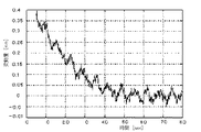
図10は、右下ローラ66に付設したエンコーダ20により転写搬送ベルト50の速度を検出してフィードバック制御した場合のベルト速度(の変動)を示すグラフである。ベルト速度はエンコーダ20の出力を積分して得たもので、グラフの縦軸は変動量、横軸は時間である。
FIG. 10 is a graph illustrating the belt speed (variation thereof) when the speed of the
図10のグラフに示すように、スタート(転写搬送ベルト50の回転開始)直後から変動量は非常に安定しており、したがって、色ずれを発生させないことが容易に判る。 As shown in the graph of FIG. 10, the amount of fluctuation is very stable immediately after the start (start of rotation of the transfer conveyance belt 50), and therefore it can be easily seen that no color misregistration occurs.
比較のために、図11にフィードバック制御を行わないときのベルト速度(の変動)をグラフにて示す。
図11のグラフにおいては、スタート後の始めの40秒間は変動量が大きく、色ずれが発生してしまうことが想像できる。なお、時間の経過とともに変動量は減少していき、40秒以降は安定している。
For comparison, FIG. 11 is a graph showing the belt speed (variation) when feedback control is not performed.
In the graph of FIG. 11, it can be imagined that the amount of variation is large for the first 40 seconds after the start, and color misregistration occurs. Note that the amount of fluctuation decreases with the passage of time, and is stable after 40 seconds.
また、図12は、本例と同様構成の転写ユニットにおいて、出口ローラ62にエンコーダを付設してフィードバック制御した場合のベルト速度(の変動)を示すグラフである。図12のグラフにおいて、フィードバック制御無しの場合(図11)と比べれば変動量の値は小さいものの、やはり始めの40秒間は変動量が大きくなっていることが判る。そして、時間の経過とともに変動量は減少していき、40秒以降は安定している。
FIG. 12 is a graph showing the belt speed (variation thereof) when the transfer unit having the same configuration as in this example is provided with an encoder attached to the
このように、本発明により、熱源の影響をほとんど受けない場所(ベルトの温度変化がほとんど起こらない個所)にベルト速度の検出手段を設けてフィードバック制御することにより、フィードバック制御の精度を向上させ、画像形成装置(タンデム方式)における色ずれを効果的に防止することができる。 Thus, according to the present invention, by providing feedback control by providing belt speed detection means in a place that is hardly affected by the heat source (where the belt temperature hardly changes), the accuracy of feedback control is improved, Color misregistration in an image forming apparatus (tandem method) can be effectively prevented.
また、微小ながらも速度検出ローラが蓄熱したとしても、その影響を受けづらい材質・構成(肉厚)にしているので、フィードバック制御をした際の検出ローラの熱膨張による転写ベルト速度の増加を抑制でき、画像形成装置(タンデム方式)における色ずれを効果的に防止することができる。また、材質や構成(肉厚)により低コスト化・振れ高精度化・低慣性モーメント化を測ることが出来るので、使用される機械の用途によって使い分けが可能となる。 In addition, even if the speed detection roller stores heat even though it is minute, it is made of a material and structure (thickness) that is not easily affected by this, so the increase in the transfer belt speed due to thermal expansion of the detection roller during feedback control is suppressed. Color misregistration in the image forming apparatus (tandem method) can be effectively prevented. In addition, it is possible to measure the cost, the accuracy of vibration, and the moment of inertia by measuring the material and configuration (thickness).
タンデム方式のフルカラー画像形成装置は、フルカラーの画像がモノクロとほぼ同様な短時間で形成可能であり、高速プリントに優れた方式であるが、高画質化の点で課題が多い。特に色ずれ防止を達成することが難しい。しかしながら、本発明により転写搬送ベルトを精度良くフィードバック制御することにより、高速プリントと色ずれ防止を両立させることができ、高画質なフルカラー画像を短時間で得ることが可能となる。 A tandem full-color image forming apparatus is capable of forming a full-color image in a short time, which is almost the same as that of monochrome, and is an excellent method for high-speed printing, but has many problems in terms of improving image quality. In particular, it is difficult to achieve color misregistration prevention. However, by accurately performing feedback control of the transfer / conveying belt according to the present invention, both high-speed printing and prevention of color misregistration can be achieved, and a high-quality full-color image can be obtained in a short time.
なお、本発明によるベルト装置のフィードバック制御は、モノクロ画像形成装置に対しても適用可能であるが、上述したように、タンデム方式のフルカラー画像形成装置における色ずれ防止に特に効果を発揮するものである。 Although the feedback control of the belt device according to the present invention can be applied to a monochrome image forming apparatus, as described above, it is particularly effective in preventing color misregistration in a tandem full-color image forming apparatus. is there.
図13は、エンコーダの付設場所によるフィードバック制御の精度の違いを説明するための模式図である。
図1に示す構成のレーザプリンタにおいては、図13に模式的に示すように、出口ローラ62が定着ユニット7により暖められ、その熱が転写搬送ベルト50に伝えられる(図中、ローラ内に太い点線で示す部分)。これにより、転写搬送ベルト50の伸び量が部分的に変化する。その変化量は負荷の影響により異なり、図13に2点鎖線で示す範囲よりも1点差線で示す範囲の方が伸びが大きい。なお、駆動ローラ63に接する範囲では、駆動ローラ63による所定の速度(基準速度)でベルトが移動する。
FIG. 13 is a schematic diagram for explaining a difference in accuracy of feedback control depending on an installation location of the encoder.
In the laser printer having the configuration shown in FIG. 1, as schematically shown in FIG. 13, the
出口ローラ62は、2点鎖線で示す範囲のベルトの伸びの影響により基準速度より若干遅く駆動される。しかしながら、1点差線で示す範囲は2点鎖線で示す範囲よりもベルトの伸びが大きいため、出口ローラ62部よりもさらに遅く駆動される。実際の画像形成(各色トナー象の重ね合わせ)に影響する部分は、各色感光体1M,1C,1Y,1Kが対向する部分、すなわち1点鎖線で示す領域であるので、2点鎖線で示す範囲の影響による速度で回転される出口ローラ62においてベルト速度を検出してフィードバック制御を行っても、フィードバック量が足りずにベルト速度は狙いの速度よりも遅くなってしまう。これは図12にも示されており、ベルトの回転開始から40秒程度は変動量が大きく(ここでは狙いの速度より遅く)なってしまっている。
The
一方、右下ローラ66は、実際の画像形成に影響する部分と同じ1点鎖線で示す範囲の影響による速度で回転されるため、右下ローラ66位置で検出したベルト速度に基づいてフィードバック制御を行うことにより、右下ローラ66部におけるベルト速度が狙いの速度となるようにフィードバック制御され、実際の画像形成に影響する部分も狙いの速度となり、図10に示すように回転開始直後から変動量が少なくなり、色ずれの発生を防止することができる。
On the other hand, since the lower
ところで、本例のレーザプリンタにおいては、ベルト速度検出手段としてのエンコーダ20が付設されている右下ローラ66の周長と、各色作像ユニットの各感光体ドラム11間の距離(以下感光体ピッチという)の比が概ね整数比となるように設定している。その理由は、ベルト速度検出手段としてロータリエンコーダを使用した場合、その構成部品の一つであるスリットディスク(本例ではディスク21、図9参照)の軸(本例では右下ローラ66の軸66a)への取り付けに非常な高精度が要求される。しかし、スリットディスクの取り付け偏心をゼロにすることは無理であり、したがって、この偏心による誤差を考慮しておく必要があるためである。
By the way, in the laser printer of this example, the circumferential length of the lower
すなわち、スリットディスクの偏心による誤差はベルトの速度変動として検出されるため、その検知結果の逆位相がフィードバック制御されて、転写搬送ベルト50が駆動される。よって、このような逆位相によるベルト速度の変動が発生した場合でも色ずれを起こさないようにする必要がある。また、同様に速度検出ローラ自身の振れ精度も同じ理由により色ずれとなる。そこで、上記のように、右下ローラ66の周長と感光体ピッチの比が概ね整数比となるように設定することで、本例の場合、右下ローラ66の周長を感光体ピッチの1/2とすることで、エンコーダ取り付け軸が2回転すると(2回転する分だけベルトが移動すると)ちょうど次の感光体にトナーが転写される位置となる。このため、各感光体位置では、ディスクの取り付け偏心によって引き起こされるベルトの速度変動周期の位相が合うために、各色画像の位置ずれ量(色ずれ量ではない)は同量となり、その結果、色ずれは発生しないことになる。当然、ローラ周長と感光体ピッチの比は本例の1:2に限定されるものではなく、整数比であれば問題ない。
That is, since an error due to the eccentricity of the slit disk is detected as a fluctuation in the belt speed, the opposite phase of the detection result is feedback controlled to drive the
速度検出ローラ自身の振れ精度に関しては、その精度を上げるしか無く、これは工法・選択する材質・構成(肉厚)で解決できる。具体的には、ステンレスやアルミの場合、鉄に比べて表面処理工程を省略できるため、高精度を得やすい。また、構成を薄肉よりも厚肉にすれば、加工時の変形を防ぎやすい。ただし、むやみに肉厚を増やすと慣性モーメントが増加しフィードバック制御性能が低下するので、両立をさせる必要がある。 As for the deflection accuracy of the speed detection roller itself, there is no choice but to improve the accuracy, and this can be solved by the construction method, the material to be selected and the configuration (wall thickness). Specifically, in the case of stainless steel or aluminum, the surface treatment process can be omitted as compared with iron, so that high accuracy can be easily obtained. Moreover, if the structure is made thicker than thin, it is easy to prevent deformation during processing. However, if the wall thickness is increased unnecessarily, the moment of inertia increases and the feedback control performance deteriorates.
なお、上記説明では煩雑化を避けるために“ローラ周長”と記載したが、より厳密には、(ローラ径にベルトの厚みの1/2を加えた値)に円周率を掛けた値と感光体ピッチが概ね整数比となるように設定するものとする。また、“概ね整数比”は、製造時の許容誤差程度とし、この程度の誤差であれば人間の視覚上色ずれを感知しないので問題ない。 In the above description, “roller circumferential length” is described in order to avoid complication, but more strictly, a value obtained by multiplying (circular diameter plus 1/2 of belt thickness) by the circumferential ratio. And the photosensitive member pitch are set to be an integer ratio. In addition, the “approximately integer ratio” is set to an allowable error at the time of manufacture, and if this error is detected, there is no problem because a color shift is not perceived by human eyes.
ここで、ベルトの伸びと色ずれ量の関係について説明する。ただしここでは、ベルトの伸び量全てが色ずれになったものとして説明する。また、ここでは、マゼンタ色の黒に対する色ずれ量について説明する。 Here, the relationship between the belt elongation and the color misregistration amount will be described. However, here, the description will be made assuming that the entire belt extension amount is color-shifted. Here, the amount of color misregistration for magenta black will be described.
マゼンタ感光体(M)と黒感光体(K)間の距離を294mmとし、ローラ径(2r)を31.2mm、ベルトの厚さ(t)を0.2mmとした場合、(2r+t/2)・π=(31.2+0.1)×3.14で31.3mm×3.14=98.28mmとなる。 When the distance between the magenta photosensitive member (M) and the black photosensitive member (K) is 294 mm, the roller diameter (2r) is 31.2 mm, and the belt thickness (t) is 0.2 mm, (2r + t / 2) Π = (31.2 + 0.1) × 3.14 and 31.3 mm × 3.14 = 98.28 mm.
基準速度時(ベルトの伸びが無い場合)のローラ径+ベルト厚さの1/2は31.3mmであり、基準速度=125.3117mm/sec,MとKの書き込みタイミング差=2.346149641secとなる。このとき、駆動ローラ回転数は76.4625rpmである。 1/2 of the roller diameter + belt thickness at the reference speed (when the belt is not stretched) is 31.3 mm, the reference speed is 125.3117 mm / sec, and the writing timing difference between M and K is 2.3461499641 sec. Become. At this time, the rotational speed of the driving roller is 76.4625 rpm.
熱の影響でベルトが伸び、厚さが0.158mmになったとすると、ベルト厚さの1/2は0.079mmであり、ローラ径+ベルト厚さの1/2は31.279mmとなる。このときのベルト速度は125.2264539mm/secとなり、基準速度に対する割合は0.068%の低下となる。この速度低下がすべて色ずれとなって現れたとすると、ベルトの伸びの割合も0.068%であり、M−K間の距離294mmの0.068%=0.19992mm、すなわち約200μmの色ずれが生じる。 If the belt is stretched due to heat and the thickness becomes 0.158 mm, 1/2 of the belt thickness is 0.079 mm and 1/2 of the roller diameter + belt thickness is 31.279 mm. The belt speed at this time is 125.2264539 mm / sec, and the ratio to the reference speed is a decrease of 0.068%. If this speed reduction appears as color misregistration, the belt stretch rate is 0.068%, 0.068% of M-K distance of 294 mm = 0.99992 mm, that is, color misregistration of about 200 μm. Occurs.
次に速度検出ローラ外径が変化した際の転写ベルト速度変化について説明する。
速度検出ローラ外径がΦ15.5⇒Φ15.51054へと0.068%増加したとすると、転写ベルト速度も同様に0.068%増加することになり、M−K間の距離294mmの0.068%=0.19992mm、すなわち約200μmの色ずれが生じる。ただし、上記ベルト伸びの際に論じた約200μmと検出ローラ膨張にて論じた約200μmでは基準色に対する色ずれ方向は逆となる。
Next, the change in the transfer belt speed when the outer diameter of the speed detection roller changes will be described.
If the outer diameter of the speed detection roller is increased by 0.068% from Φ15.5 to Φ15.51054, the transfer belt speed is also increased by 0.068%, and the distance between M and K is 0.4 mm. 068% = 0.99992 mm, that is, a color shift of about 200 μm occurs. However, the color misregistration direction with respect to the reference color is reversed between about 200 μm discussed when the belt is stretched and about 200 μm discussed regarding the detection roller expansion.
ここで説明したように、熱の影響でベルトが部分的に伸びるとベルト速度が低下したり、速度検出ローラが膨張したりするとベルト速度が増加して色ずれが発生する。しかし、本発明によりベルト速度を検出してフィードバック制御することにより色ずれの発生を効果的に防止することができる。また、上記のようにローラ周長と感光体ピッチの比を概ね整数比とすることにより、エンコーダディスクの偏心誤差によりベルト速度の検出に誤差が発生した場合でも、そのフィードバックによる色ずれの発生が防止される。 As described herein, when the belt partially extends due to heat, the belt speed decreases or when the speed detection roller expands, the belt speed increases and color misregistration occurs. However, occurrence of color misregistration can be effectively prevented by detecting the belt speed and performing feedback control according to the present invention. In addition, by setting the ratio of the roller circumference to the photoreceptor pitch to be an integer ratio as described above, even if an error occurs in the belt speed detection due to the eccentricity error of the encoder disk, color misregistration due to the feedback occurs. Is prevented.
ところで、本例では、転写搬送ベルト50の速度検出手段としてロータリエンコーダを用いた。ロータリエンコーダは簡単な構成でエンコーダの構成要素を覆う(密閉する)ことができ、トナーやほこり等による汚れの影響を容易に防ぐことができる。また、ロータリエンコーダは単品でセンサ部の調整を行うことが可能であり高精度の維持が容易である。すなわち、速度検出手段としてのロータリエンコーダは、高耐久・高精度を比較的簡単に実現することができる。
By the way, in this example, a rotary encoder is used as the speed detection means of the
ただし、転写搬送ベルト50の速度検出手段としてはロータリエンコーダに限らず、他の任意の構成のものを使用可能である。例えば、転写搬送ベルト50上に所定の基準スケールを設け、これをレーザ光などにより読み取ることでベルト速度を検出することもできる。このような任意の方法でベルト速度を検出してフィードバック制御を行うことにより、色ずれの発生を防止することが可能である。
However, the speed detection means of the transfer /
また、本例では、ベルトの温度変化がほとんど起こらない個所として右下ローラ66に速度検出手段としてのロータリエンコーダ20を付設したが、ロータリエンコーダを設けるローラは右下ローラ66に限定されない。例えば、定着ユニットから離れた場所にある入口ローラ61もエンコーダの設置場所としては候補に上げられるが、本例の場合上述したように入口ローラ61が移動可能に設けられているので、速度検出手段の設置が難しいため、固定配置された(移動しない)ローラのうちで熱源(定着装置、光書き込み装置など)から最も遠い個所にあるローラにエンコーダを設置したものである。
Further, in this example, the
また、本例では、エンコーダ20を付設した右下ローラ66と駆動ローラ63間に、ベルトに対してテンションを付与するテンションローラ65を設けている。このとき、各ローラ63,65,66のベルト移動方向における位置関係は、駆動ローラ63の下流側にローラ65、ローラ65のさらに下流側にローラ66があるものとする。このような位置関係でエンコーダ20を付設した右下ローラ66と駆動ローラ63間にテンションローラ65を配置することで、エンコーダが付設された右下ローラ66部でのベルトのスリップが防止されるため、より正確にベルト速度の検出が可能となる。
In this example, a
次に、本発明の第2の実施形態として、中間転写ベルトのフィードバック制御を行うものを説明する。
図14に示す画像形成装置は、中間転写ベルト30の上辺に4色分の作像ユニットを並べて配置した4連タンデム方式のフルカラープリンタである。中間転写ベルト30は、従動ローラ31,駆動ローラ32,対向ローラ33,押し込みローラ34の4つのローラに掛け回されている。この中間転写ベルト30の下に、対向ローラ33部で中間転写ベルト30に接して転写ベルト35が配設されている。その転写ベルト35に隣接して定着ユニット7が配置されている。その他、図1のレーザプリンタと同じ部分又は同等の部分には、図1と同じ符号を付して説明を省略する。
Next, a second embodiment of the present invention that performs feedback control of the intermediate transfer belt will be described.
The image forming apparatus shown in FIG. 14 is a quadruple tandem full color printer in which image forming units for four colors are arranged on the upper side of the
本例の中間転写方式のフルカラープリンタにおいては、各作像ユニットの感光体ドラム上に形成した各色画像を中間転写ベルト30上に重ね転写し、中間転写ベルト30上でフルカラー画像を形成する。そのフルカラー画像は、給紙カセット3から給送された転写紙上に、対向ローラ33と転写ベルト35が対向する転写位置にて転写され、定着ユニット7へ搬送されてトナー像が定着される。定着後の用紙は装置上面の排紙トレイ8又は装置側面の排紙トレイ(符号なし)に排出可能である。
In the intermediate transfer type full-color printer of this example, each color image formed on the photosensitive drum of each image forming unit is transferred onto the
さて、本実施形態においては、中間転写ベルト30の速度を図示しない速度検出手段により検出し、中間転写ベルト30が狙いの速度となるように制御する、いわゆるフィードバック制御を行っている。中間転写ベルト30の速度検出手段としては、任意の構成のものを採用可能であるが、ここでは、ロータリエンコーダを従動ローラ31に付設するものとする。ロータリエンコーダの構成・動作については図1の実施形態の場合と同様である。
In the present embodiment, so-called feedback control is performed in which the speed of the
本例においてロータリエンコーダが付設される従動ローラ31は、画像形成装置内で最大の熱源である定着ユニット7から最も遠くにある(中間転写ベルト30が掛け渡されているローラのうち)ローラであり、ベルトの温度変化がほとんど起こらない個所に位置している。
In this example, the driven
仮に、駆動ローラ32あるいは押し込みローラ34の軸にエンコーダを付設した場合、ローラ32,34は定着ユニット7の近くに位置しているため、ここで中間転写ベルト30の速度を検出してフィードバック制御を行ったとしても、図1の前記実施形態において出口ローラ62で転写搬送ベルト50の速度を検出した場合と同様に精度の良いフィードバック制御ができない。また、速度検出ローラが熱膨張した場合も、第一実施形態にて説明したことと同様の現象となる。
If an encoder is attached to the shaft of the
しかし、本実施形態においても、[1]:定着装置の熱の影響をほとんど受けない場所(ベルトの温度変化がほとんど起こらない個所)に中間転写ベルトの速度検出手段を設けてフィードバック制御すること、[2]:微小ながらも速度検出ローラが蓄熱したとしても、その影響を受けづらい材質・構成(肉厚)にすることにより、フィードバック制御の精度を向上させ、色ずれを効果的に防止することができる。すなわち、中間転写方式のタンデム型カラー画像形成装置における色ずれを効果的に防止することができる。 However, also in this embodiment, [1]: feedback control by providing a speed detecting means for the intermediate transfer belt at a place where the influence of the fixing device is hardly affected (a place where the belt temperature hardly changes). [2]: Even if it is very small, even if the speed detection roller stores heat, it is possible to improve the accuracy of feedback control and effectively prevent color misregistration by using a material and configuration (thickness) that is not easily affected by the effect. Can do. That is, color misregistration in the intermediate transfer type tandem color image forming apparatus can be effectively prevented.
なお、中間転写ベルトの速度検出手段として、ロータリエンコーダ以外のもの、例えば中間転写ベルト上に基準スケールを設けて光学的に読み取る方式などを採用できることは、前記第1の実施形態と同様である。 It is to be noted that, as in the first embodiment, the intermediate transfer belt speed detecting means other than the rotary encoder, for example, a method of optically reading by providing a reference scale on the intermediate transfer belt can be adopted.
また、速度検出手段をロータリエンコーダとする場合、そのディスクが装着されるローラ(本例では従動ローラ31)の周長と感光体ピッチの比が概ね整数比となるように設定することで、色ずれの発生を防止できることも同様である。
Further, when the speed detecting means is a rotary encoder, the ratio of the circumferential length of the roller (the driven
なお、本発明によるベルト装置のフィードバック制御は、中間転写方式のモノクロ画像形成装置に対しても適用可能であるが、上述したように、中間転写方式のタンデム型フルカラー画像形成装置における色ずれ防止に特に効果を発揮するものである。 The feedback control of the belt device according to the present invention can also be applied to an intermediate transfer type monochrome image forming apparatus. However, as described above, in the intermediate transfer type tandem type full color image forming apparatus, color belt prevention can be prevented. This is particularly effective.
次に、本発明の第3の実施形態として、感光体ベルトのフィードバック制御を行うものを説明する。
図15は、像担持体としてベルト状感光体を備えるフルカラー画像形成装置の要部構成を示す断面図である。
Next, as a third embodiment of the present invention, one that performs feedback control of a photosensitive belt will be described.
FIG. 15 is a cross-sectional view showing the main configuration of a full-color image forming apparatus having a belt-like photoconductor as an image carrier.
この図に示すように、本例においては、三角形状に張設された感光体ベルト40の上辺に沿って、44M,44C,44Y,44Kの4つの現像装置がタンデム配置されている。感光体ベルト40は、従動ローラ41,出口ローラ42,駆動ローラ43の3つのローラに掛け渡されている。
As shown in this figure, in this example, four developing
感光体ベルト40の図において左方には中間転写ドラム45が配設されている。また、その中間転写ドラム45の図において左方には転写ベルト46が配置されている。そして、転写ベルト46の上方に定着ユニット7が配置されている。その他、図1のレーザプリンタと同じ部分又は同等の部分には、図1と同じ符号を付して説明を省略する。
An
本例の中間転写方式のフルカラー画像形成装置においては、感光体ベルト40上に各色画像情報に対応して形成した静電潜像に各色現像装置44からトナーを付与して可視像化し、これを順番に中間転写ドラム45に重ね転写することで中間転写ドラム45上でフルカラー画像を形成する。そのフルカラー画像は、給紙カセット3から給送された転写紙上に、中間転写ドラム45と転写ベルト46が対向する転写位置にて転写され、定着ユニット7へ搬送されてトナー像が定着される。定着後の用紙は装置上面の排紙トレイ8に排出される。
In the intermediate transfer type full-color image forming apparatus of this example, toner is applied to each electrostatic latent image formed on the
さて、本実施形態においては、感光体ベルト40の速度を図示しない速度検出手段により検出し、感光体ベルト40が狙いの速度となるように制御する、いわゆるフィードバック制御を行っている。感光体ベルト40の速度検出手段としては、任意の構成のものを採用可能であるが、ここでは、ロータリエンコーダを従動ローラ41に付設するものとする。ロータリエンコーダの構成・動作については図1の実施形態の場合と同様である。
In the present embodiment, so-called feedback control is performed in which the speed of the
本例においてロータリエンコーダが付設される従動ローラ41は、画像形成装置内で最大の熱源である定着ユニット7から最も遠くにある(感光体ベルト40が掛け渡されているローラのうち)ローラであり、ベルトの温度変化がほとんど起こらない個所に位置している。
In this example, the driven
仮に、出口ローラ42の軸にエンコーダを付設した場合、出口ローラ42は定着ユニット7の近くに位置しているため、ここで感光体ベルト40の速度を検出してフィードバック制御を行ったとしても、図1の前記実施形態において出口ローラ62で転写搬送ベルト50の速度を検出した場合と同様に精度の良いフィードバック制御ができない。また、速度検出ローラが熱膨張した場合も、第一実施形態にて説明したことと同様の現象となる。
If an encoder is attached to the shaft of the
しかし、本実施形態においても、[1]:定着装置の熱の影響をほとんど受けない場所(ベルトの温度変化がほとんど起こらない個所)に感光体ベルト40の速度検出手段を設けてフィードバック制御すること、[2]:微小ながらも速度検出ローラが蓄熱したとしても、その影響を受けづらい材質・構成(肉厚)にすることにより、フィードバック制御の精度を向上させ、色ずれを効果的に防止することができる。すなわち、感光体ベルトを備えるフルカラー画像形成装置における色ずれを効果的に防止することができる。また、本例の場合、定着ユニット7との間に中間転写ドラム45が有る駆動ローラ43にエンコーダを付設しても良い。この場合、光書き込み装置2からの距離が遠くなるので、光書き込み装置2の熱の影響を受けにくくなる。
However, also in the present embodiment, [1]: feedback control is performed by providing speed detection means for the
なお、中間転写ベルトの速度検出手段として、ロータリエンコーダ以外のもの、例えば中間転写ベルト上に基準スケールを設けて光学的に読み取る方式などを採用できることは、前記第1の実施形態と同様である。 It is to be noted that, as in the first embodiment, the intermediate transfer belt speed detecting means other than the rotary encoder, for example, a method of optically reading by providing a reference scale on the intermediate transfer belt can be adopted.
以上、本発明を図示の実施形態により説明したが、本発明はこれに限定されるものではない。例えば、ベルト装置の速度変動を検出する手段は、ロータリエンコーダに限らず任意の構成のものを採用し得るものである。 As mentioned above, although this invention was demonstrated by embodiment of illustration, this invention is not limited to this. For example, the means for detecting the speed fluctuation of the belt device is not limited to the rotary encoder, and may employ any configuration.
また、搬送される用紙に像担持体(感光体)から直接各色画像を転写する方式(第1の実施形態)において、転写搬送ベルトは移動可能(少なくともベルトの一部分が一部の感光体に対して接離可能)なものに限らず、固定配置された(常に像担持体に接触している)転写搬送ベルトであっても良い。 Also, in the system (first embodiment) in which each color image is directly transferred from the image carrier (photosensitive member) to the conveyed paper, the transfer / conveying belt is movable (at least a part of the belt is part of the photosensitive member). And a transfer / conveying belt that is fixedly arranged (always in contact with the image carrier).
また、タンデム方式は4連(4色)に限らず、3色のフルカラーあるいは2色の多色方式であっても良く、色数は限定されない。
画像形成装置における光書き込み装置、現像装置、定着装置等の各部構成は、任意な構成のものを採用することができる。もちろん、画像形成装置としてはプリンタに限らず、複写機やファクシミリであっても良いことは言うまでもない。
Further, the tandem method is not limited to four (four colors), and may be a full color of three colors or a multicolor method of two colors, and the number of colors is not limited.
Arbitrary configurations can be adopted as the components of the optical writing device, the developing device, the fixing device, and the like in the image forming apparatus. Needless to say, the image forming apparatus is not limited to a printer, and may be a copying machine or a facsimile.
1M,1C,1Y,1K 作像ユニット
2 光書込ユニット
3,4 給紙カセット
6 転写ユニット
11M、11C、11Y、11K 感光体ドラム
20 エンコーダ
30 中間転写ベルト
31 従動ローラ
40 感光体ベルト
41 従動ローラ
44M,44C,44Y,44K 現像装置
62 出口ローラ
63 駆動ローラ
65 テンションローラ
66 右下ローラ
66a 右下ローラの軸
70 モータ
1M, 1C, 1Y, 1K
Claims (18)
前記ベルト搬送装置の速度を検出する速度検出手段を設け、該速度速度検出手段の検出値に基づいて前記ベルト搬送装置の速度が狙いの速度になるようにフィードバック制御するとともに、
前記速度検出手段が、ベルト温度変化がほとんど起こらない個所に配置されており、該速度検出手段が前記ベルト搬送装置が掛け渡されるローラの回転速度を検出するローラ回転速度検出手段としてのロータリエンコーダであり、
前記ベルト搬送装置への記録媒体導入部に配置される入口ローラに対向して対向ローラが設けられ、前記ロータリエンコーダが速度を検出するローラが、前記ベルト搬送装置の駆動ローラと前記入口ローラの間に配置されるローラであり、該ロータリエンコーダが速度を検出するローラと前記駆動ローラとの間に前記ベルトにテンションを付与するテンションローラが設けられ、ベルト回動方向において前記駆動ローラの下流側に前記テンションローラが、前記テンションローラの下流側に前記速度を検出するローラが配置され、
前記ベルト搬送装置に対向して複数の像担持体が並設され、各像担持体上に形成した画像を前記ベルト搬送装置により搬送される記録媒体上に重ね転写してカラー画像の形成が可能であって、
前記複数の像担持体と対向するベルト辺の下流側に前記駆動ローラが配置されることを特徴とする画像形成装置。 An image having an image carrier, a belt carrying device for carrying and carrying a recording medium onto which an image formed on the image carrier is transferred, and a fixing device for fixing an unfixed image transferred onto the recording medium In the forming device,
Provided with a speed detection means for detecting the speed of the belt conveying device, and based on a detection value of the speed speed detecting means, feedback control is performed so that the speed of the belt conveying device becomes a target speed,
The speed detecting means is arranged at a place where the belt temperature hardly changes, and the speed detecting means is a rotary encoder as a roller rotational speed detecting means for detecting the rotational speed of the roller over which the belt conveying device is stretched. Yes,
A counter roller is provided opposite to the inlet roller disposed in the recording medium introduction portion to the belt conveying device, and a roller for detecting the speed by the rotary encoder is between the driving roller of the belt conveying device and the inlet roller. Ri Ah rollers disposed, the rotary encoder is a tension roller for applying tension to said belt between said drive roller and roller for detecting the speed provided, downstream of the driving roller in the belt rotation direction The tension roller is disposed on the downstream side of the tension roller to detect the speed,
A plurality of image carriers are arranged in parallel to face the belt conveyance device, and an image formed on each image carrier can be transferred onto a recording medium conveyed by the belt conveyance device to form a color image. Because
The image forming apparatus , wherein the driving roller is disposed on a downstream side of a belt side facing the plurality of image carriers .
Priority Applications (5)
| Application Number | Priority Date | Filing Date | Title |
|---|---|---|---|
| JP2004136026A JP4359533B2 (en) | 2003-08-08 | 2004-04-30 | Image forming apparatus |
| EP04016817.1A EP1498785B1 (en) | 2003-07-18 | 2004-07-16 | Image forming apparatus with a speed control of a belt |
| CNB2004100713096A CN100489689C (en) | 2003-07-18 | 2004-07-19 | Apparatus for image forming |
| US10/893,391 US7257339B2 (en) | 2003-07-18 | 2004-07-19 | Method and apparatus for image forming capable of effectively reducing unevenness of density and color displacement of images |
| US11/761,682 US7509074B2 (en) | 2003-07-18 | 2007-06-12 | Method and apparatus for image forming capable of effectively reducing unevenness of density and color displacement of images |
Applications Claiming Priority (2)
| Application Number | Priority Date | Filing Date | Title |
|---|---|---|---|
| JP2003290282 | 2003-08-08 | ||
| JP2004136026A JP4359533B2 (en) | 2003-08-08 | 2004-04-30 | Image forming apparatus |
Publications (2)
| Publication Number | Publication Date |
|---|---|
| JP2005092179A JP2005092179A (en) | 2005-04-07 |
| JP4359533B2 true JP4359533B2 (en) | 2009-11-04 |
Family
ID=34466776
Family Applications (1)
| Application Number | Title | Priority Date | Filing Date |
|---|---|---|---|
| JP2004136026A Expired - Fee Related JP4359533B2 (en) | 2003-07-18 | 2004-04-30 | Image forming apparatus |
Country Status (1)
| Country | Link |
|---|---|
| JP (1) | JP4359533B2 (en) |
Families Citing this family (4)
| Publication number | Priority date | Publication date | Assignee | Title |
|---|---|---|---|---|
| JP4820622B2 (en) * | 2005-10-31 | 2011-11-24 | 株式会社リコー | Image forming apparatus |
| JP4496154B2 (en) * | 2005-10-31 | 2010-07-07 | 株式会社リコー | Rotary encoder, roller member, belt conveying device, image forming device |
| JP4363400B2 (en) | 2005-12-27 | 2009-11-11 | ブラザー工業株式会社 | Image forming apparatus |
| JP4860318B2 (en) * | 2006-03-29 | 2012-01-25 | 京セラミタ株式会社 | Driving device and driving method used in image forming apparatus |
-
2004
- 2004-04-30 JP JP2004136026A patent/JP4359533B2/en not_active Expired - Fee Related
Also Published As
| Publication number | Publication date |
|---|---|
| JP2005092179A (en) | 2005-04-07 |
Similar Documents
| Publication | Publication Date | Title |
|---|---|---|
| US7257339B2 (en) | Method and apparatus for image forming capable of effectively reducing unevenness of density and color displacement of images | |
| JP5247413B2 (en) | Belt drive device and image forming apparatus having the same | |
| JP5631021B2 (en) | Image forming apparatus | |
| JP5397776B2 (en) | Image forming apparatus | |
| JP5455447B2 (en) | Belt member conveying apparatus and image forming apparatus provided with the same | |
| US20080310891A1 (en) | Image forming apparatus | |
| JP2010281943A (en) | Image forming apparatus | |
| JP5274397B2 (en) | Driving device and image forming apparatus | |
| JP5441757B2 (en) | Image forming apparatus | |
| JP2005338884A (en) | Image forming apparatus | |
| US10152001B2 (en) | Image forming apparatus | |
| JP4359533B2 (en) | Image forming apparatus | |
| US9971283B2 (en) | Belt conveyance apparatus and image forming apparatus for reduced belt buckling | |
| JP2005043863A (en) | Image forming apparatus | |
| JP4632703B2 (en) | Image forming apparatus | |
| JP2006215386A (en) | Image forming apparatus | |
| JP5473450B2 (en) | Image forming apparatus | |
| JP2008129057A (en) | Belt moving device and image forming apparatus | |
| JP2007199433A (en) | Transfer device and image forming apparatus | |
| JP4857022B2 (en) | Image forming apparatus | |
| JP2020160346A (en) | Image forming device | |
| JP2012008561A (en) | Endless belt carrier device and image-forming apparatus | |
| JP3548164B2 (en) | Image forming device | |
| JP2011033771A (en) | Paper conveying device and image forming apparatus | |
| JP5448915B2 (en) | Image forming apparatus |
Legal Events
| Date | Code | Title | Description |
|---|---|---|---|
| A621 | Written request for application examination |
Free format text: JAPANESE INTERMEDIATE CODE: A621 Effective date: 20060704 |
|
| A977 | Report on retrieval |
Free format text: JAPANESE INTERMEDIATE CODE: A971007 Effective date: 20090122 |
|
| A131 | Notification of reasons for refusal |
Free format text: JAPANESE INTERMEDIATE CODE: A131 Effective date: 20090127 |
|
| A521 | Request for written amendment filed |
Free format text: JAPANESE INTERMEDIATE CODE: A523 Effective date: 20090330 |
|
| A131 | Notification of reasons for refusal |
Free format text: JAPANESE INTERMEDIATE CODE: A131 Effective date: 20090428 |
|
| A521 | Request for written amendment filed |
Free format text: JAPANESE INTERMEDIATE CODE: A523 Effective date: 20090626 |
|
| TRDD | Decision of grant or rejection written | ||
| A01 | Written decision to grant a patent or to grant a registration (utility model) |
Free format text: JAPANESE INTERMEDIATE CODE: A01 Effective date: 20090804 |
|
| A01 | Written decision to grant a patent or to grant a registration (utility model) |
Free format text: JAPANESE INTERMEDIATE CODE: A01 |
|
| A61 | First payment of annual fees (during grant procedure) |
Free format text: JAPANESE INTERMEDIATE CODE: A61 Effective date: 20090810 |
|
| FPAY | Renewal fee payment (event date is renewal date of database) |
Free format text: PAYMENT UNTIL: 20120814 Year of fee payment: 3 |
|
| FPAY | Renewal fee payment (event date is renewal date of database) |
Free format text: PAYMENT UNTIL: 20120814 Year of fee payment: 3 |
|
| FPAY | Renewal fee payment (event date is renewal date of database) |
Free format text: PAYMENT UNTIL: 20120814 Year of fee payment: 3 |
|
| FPAY | Renewal fee payment (event date is renewal date of database) |
Free format text: PAYMENT UNTIL: 20130814 Year of fee payment: 4 |
|
| LAPS | Cancellation because of no payment of annual fees |