JP4358397B2 - Network element synchronization in synchronous digital communication networks. - Google Patents
Network element synchronization in synchronous digital communication networks. Download PDFInfo
- Publication number
- JP4358397B2 JP4358397B2 JP2000001280A JP2000001280A JP4358397B2 JP 4358397 B2 JP4358397 B2 JP 4358397B2 JP 2000001280 A JP2000001280 A JP 2000001280A JP 2000001280 A JP2000001280 A JP 2000001280A JP 4358397 B2 JP4358397 B2 JP 4358397B2
- Authority
- JP
- Japan
- Prior art keywords
- network
- node
- clock
- stm
- network element
- Prior art date
- Legal status (The legal status is an assumption and is not a legal conclusion. Google has not performed a legal analysis and makes no representation as to the accuracy of the status listed.)
- Expired - Fee Related
Links
- 230000001360 synchronised effect Effects 0.000 title claims description 35
- 238000004891 communication Methods 0.000 title claims description 30
- 238000000034 method Methods 0.000 claims description 17
- 101100142275 Saccharomyces cerevisiae (strain ATCC 204508 / S288c) RPL1A gene Proteins 0.000 claims description 12
- 101100476983 Saccharomyces cerevisiae (strain ATCC 204508 / S288c) SDT1 gene Proteins 0.000 claims description 12
- 102100040862 Dual specificity protein kinase CLK1 Human genes 0.000 claims description 10
- 101000749294 Homo sapiens Dual specificity protein kinase CLK1 Proteins 0.000 claims description 10
- 230000005540 biological transmission Effects 0.000 abstract description 14
- 238000010586 diagram Methods 0.000 description 5
- 239000000284 extract Substances 0.000 description 4
- 230000003287 optical effect Effects 0.000 description 3
- 238000011084 recovery Methods 0.000 description 2
- 239000004065 semiconductor Substances 0.000 description 2
- 230000001419 dependent effect Effects 0.000 description 1
- 230000006870 function Effects 0.000 description 1
- 230000007257 malfunction Effects 0.000 description 1
- 230000004044 response Effects 0.000 description 1
Images


Classifications
-
- H—ELECTRICITY
- H04—ELECTRIC COMMUNICATION TECHNIQUE
- H04J—MULTIPLEX COMMUNICATION
- H04J3/00—Time-division multiplex systems
- H04J3/02—Details
- H04J3/06—Synchronising arrangements
- H04J3/0635—Clock or time synchronisation in a network
- H04J3/0638—Clock or time synchronisation among nodes; Internode synchronisation
- H04J3/0641—Change of the master or reference, e.g. take-over or failure of the master
-
- H—ELECTRICITY
- H04—ELECTRIC COMMUNICATION TECHNIQUE
- H04J—MULTIPLEX COMMUNICATION
- H04J3/00—Time-division multiplex systems
- H04J3/02—Details
- H04J3/06—Synchronising arrangements
- H04J3/0635—Clock or time synchronisation in a network
- H04J3/0679—Clock or time synchronisation in a network by determining clock distribution path in a network
Landscapes
- Engineering & Computer Science (AREA)
- Computer Networks & Wireless Communication (AREA)
- Signal Processing (AREA)
- Synchronisation In Digital Transmission Systems (AREA)
- Data Exchanges In Wide-Area Networks (AREA)
- Time-Division Multiplex Systems (AREA)
- Telephonic Communication Services (AREA)
- Mobile Radio Communication Systems (AREA)
Abstract
Description
【0001】
【発明の属する技術分野】
本発明は、請求項1のプリアンブルに記載の同期ディジタル通信ネットワークにおいてネットワークエレメントを同期化する方法、請求項6のプリアンブルに記載の同期ディジタル通信ネットワーク用のネットワークエレメント、および請求項7に記載のネットワーク管理設備に関する。
【0002】
【従来の技術】
同期ディジタル通信ネットワークのネットワークエレメントは、同期ディジタルハイアラーキ(SDH)または同期光ネットワーク(SONET)用のITU−T勧告に従って動作する。アド/ドロップマルチプレクサ、クロスコネクト、またはラインマルチプレクサが、「ネットワークエレメント」として理解されている。そのような通信ネットワークにおける情報伝送の間、すべてのネットワークエレメントが同期して動作することが不可欠である。これは、ネットワークエレメントの相互の同期化またはマスタ−スレーブ同期化によって達成される。その際、各ネットワークエレメントは、受信したメッセージ信号からクロック信号を抽出し、その内部のクロック生成装置をこの外部クロック信号で同期化する。1つまたは複数の1次クロック生成装置は、ネットワークの非常に正確な基準クロックを供給する。
【0003】
タイミング基準としてのメッセージ信号の選択を改善するために、メッセージ信号の一部として送信される同期ステータスメッセージ(SSM)が導入された。SSMは、送信側ネットワークエレメントが同期化される基準クロックの品質を示す。タイミング基準の選択は、次のようにSSMに基づく。ネットワークエレメントは、SSMが最高のクロック品質を示す情報信号を、タイミング基準として選択する。SSMとして、情報信号がタイミング基準として選択されたネットワークエレメントに返送すべきメッセージ「DNU」(「do not use for synchronization」)が定義された。
【0004】
同期化中、タイミングループが生成されないこと、すなわち、2つのネットワークエレメントが互いを同期クロックソースとして選択しないことを保証するように注意しなければならない。特に2つのネットワークエレメント間に2つ以上の並行伝送経路が存在する場合に、タイミングループが作成される危険性が大きい。そのような並行伝送経路は「バンドル(bundles)」とも呼ばれる。SSM「DNU」のみを使用することで、タイミングループの生成がすべての考えられる状況で回避できるというわけではない。
【0005】
タイミングループを回避するために、欧州特許出願EP0723344は、2つのクラスのインタフェース装置を定義することを提案する。第1のクラスのインタフェース装置で受信される情報信号だけが、タイミング基準として選択でき、一方、第2のクラスのインタフェース装置で受信される情報信号は、基準クロックを選択する際には無視されなければならない。ネットワークの適切なコンフィグレーション、例えば、第1のクラスのインタフェースのみを第2のクラスのインタフェースに接続することで、タイミングループを回避できる。ただし、この解決策は、正しいネットワークコンフィグレーションに依存するので、エラーを生じやすい。特に、並行伝送経路のバンドルが存在する場合、エラーがコンフィグレーションに入りこむことがあり、その結果、タイミングループが生成される。
【0006】
欧州特許出願EP0849904は、タイミングループを回避する別の方法を提案する。基準クロックの選択は、ネットワークノードの中央クロック生成装置において行われる。選択されたクロックソースは、中央ネットワーク管理設備に伝達され、中央ネットワーク管理設備は、その基準クロックを中央クロック生成装置から受信するノードの各ネットワークエレメントに、その出力のどれでどのSSMを送信するかを指示する。このようにして、SSM「DNU」は、タイミングループの生成の危険を含むすべての出力で送信でき、それによって、タイミングループの生成が効果的に防止される。ただし、ネットワーク管理設備は、各ネットワークエレメントの各出力に、SSMを明示的に割り当てなければならないので、この方法は複雑である。また、この方法は、基本的に正しいネットワークコンフィグレーションに依存する。さらに、クロック生成装置とネットワークエレメントとの間に、SSMを伝送する手段を有する複数のクロックインタフェースを提供しなければならない。これによって、装置の複雑性とコストが増大し、現在利用可能なネットワークエレメントにおいては供給できない。
【0007】
【発明が解決しようとする課題】
本発明の目的は、特に並行伝送経路が存在する場合に、タイミングループの生成の危険を低減するが、簡単な技術的手段で管理できるネットワークエレメントを同期化する方法を提供することである。本発明の別の目的は、この方法を遂行するのに適したネットワークエレメントとネットワーク管理設備を提供することである。
【0008】
【課題を解決するための手段】
最初に述べた目的は、請求項1の特徴によって達成され、別の目的は、請求項6および7の特徴によって達成される。本発明の別の有利な態様は、従属請求項に記載される。
【0009】
本発明は、添付の図面に関連する以下の2つの実施形態の説明を参照することでより明らかになる。
【0010】
本発明の基本的な考え方は、ネットワークエレメントまたは中央クロック生成装置ではなく、中央ネットワーク管理設備によってタイミング基準を選択することである。ともかく存在するネットワーク管理設備には、ネットワークの構成とコンフィグレーションに関するすべての情報が記憶されている。別の基本的な考え方は、ネットワークエレメントが新しい選択の必要を決定すると、その入力で受信したすべてのメッセージ信号について、メッセージ信号内のそれぞれの同期メッセージを、ネットワーク管理設備に送信し、送信された同期ステータスメッセージとネットワークの構成とコンフィグレーションに関する情報とに基づいて、受信したメッセージ信号の1つを新しいタイミング基準として選択し、この選択をネットワークエレメントに通知するというものである。
【0011】
よく知られているように、ネットワークエレメントと中央ネットワーク管理設備との間の既存のQインタフェースを介した情報伝送は、数秒から数分かかる。ただし、本発明は、通信ネットワークにおける情報伝送は、その基準クロックソースが失われたまたは障害になった後に、ネットワークエレメントが直ちに再同期化されなくても、大幅に劣化することはないという認識に基づく。その場合、本発明によれば、ネットワークエレメントは、自由な非同期モード、いわゆるホールドオーバ(holdover)モードに切り替わり、ネットワーク管理設備によって新しい選択が通知されるまで待つことになる。Qインタフェースを介した情報伝送によって引き起こされる最大数分の遅れ、およびネットワーク管理設備における待ち時間と処理時間は、ネットワークの運用にとって致命的ではない。
【0012】
あるいは、基準クロックソースが失われた後で、従来技術で一般に行われているように、ネットワークエレメント自体が、新しい基準クロックソースを選択することもある。ただし、この選択は、ネットワーク管理設備によって新しい基準クロックソースが選択されるまでの時間つなぎをするための一時的なものにすぎない。ネットワーク管理設備が、ネットワークエレメントに新しい基準クロックソースを伝達すると、ネットワークエレメントは、新しい基準クロックソースに切り替わる。
【0013】
【発明の実施の形態】
同期ディジタルハイアラーキ(SDH)用の勧告に基づく同期ディジタル通信ネットワーク管理設備NETが、図1に示されている。NETは、光または電気伝送媒体LINKによって双方向に相互接続されたいくつかのネットワークエレメントNE1〜NE5および中央ネットワーク管理設備TMNからなる。ネットワーク管理設備TMNは、ネットワークエレメント間の論理接続を切り替え、エラーメッセージおよびアラームを監視し、ネットワークNETをコンフィグレート(設定)する働きをする。さらに、本発明によれば、ネットワーク管理設備TMNは、基準クロックソースを各ネットワークエレメントに割り当てるように設計されている。ネットワークエレメントNE1で、1次基準クロックPRCからの極めて正確な基準クロック信号REFがネットワークに供給される。
【0014】
ネットワークエレメントNE1〜NE5は、伝送媒体LINKを介して、同期トランスポートモジュールSTM−Nの形式で構成された同期メッセージ信号を交換する。同期化は、受信したメッセージ信号をネットワークエレメントごとにタイミング基準として選択し、ネットワークエレメントにおける選択されたメッセージ信号からクロック信号を抽出し、ネットワークエレメントの内部クロック生成装置をこのクロック信号に合わせて調整することで達成される。2つのネットワークエレメント間のリンクが障害になった場合、再同期化が必要になることがある。これには、別の受信メッセージ信号を2つのネットワークエレメントの新しいタイミング基準として選択することが必要である。
【0015】
基準クロックソースの選択は、同期トランスポートモジュールに含まれ、同期トランスポートモジュールと共に伝送され、送信側ネットワークエレメントのそれぞれのクロック品質を示す、同期ステータスメッセージSSMによって行われる。SSMでは、表1に掲げたメッセージが定義されている。
【0016】
【表1】
【0017】
図2は、本発明によるネットワークエレメントの一実施形態を示す。ネットワークエレメントNEは、メッセージ信号STM−N1〜STM−Nmをそれぞれ受信するm個の入力を有する。メッセージ信号は、SDHシステム用の多重レベルN(N=1、2、4、16、...)の同期トランスポートモジュールSTM−Nとして構成される。QインタフェースQを介して、ネットワークエレメントは、中央管理設備TMNと通信する。ブロック図は、同期化に不可欠のネットワークエレメントNEの装置および接続のみを示す。
【0018】
m個の入力の各々に、ネットワークエレメントNEは、インタフェース回路IN1〜INmを有する。各インタフェース回路において、クロック信号CLK1〜CLKmが、受信されたメッセージ信号から抽出される。クロック信号CLK1〜CLKmは、それぞれの接続を介して選択装置SELに供給される。また、インタフェース回路IN1〜INmは、同期トランスポートモジュールSTM−N1〜STM−Nmのオーバヘッド領域に含まれる同期ステータスメッセージSSM1〜SSMmを読み出し、それらを通信ユニットCOMに渡す。通信ユニットCOMは、QインタフェースQを介して、ネットワーク管理設備TMNに接続される。通信ユニットCOMは、それぞれの同期ステータスメッセージが受信されたメッセージ信号のどれから発生しているかに関する情報と共に、同期ステータスメッセージSSM1〜SSMmを、ネットワーク管理設備TMNに送信する。次いで、ネットワーク管理設備TMNは、同期ステータスメッセージを評価し、これらのメッセージと通信ネットワークのコンフィグレーションに関する記憶された情報に基づいて、抽出されたクロック信号CLK1〜CLKmの1つを、タイミング基準として選択する。ネットワーク管理設備TMNは、Qインタフェースを介して、この選択を、ネットワークエレメントNEの通信ユニットCOMに通知する。通信ユニットCOMは、通知を選択ユニットSELに渡し、選択ユニットSELは、それに応答して、選択されたクロック信号を内部クロック生成装置PLLに転送する。通信ユニットCOMは、例えばネットワークエレメントの制御装置、いわゆるネットワークエレメントマネージャでもよい。
【0019】
内部クロック生成装置PLLは、例えば、自由な非同期モードにおいて、ITU−T G.812で定義された品質を有するクロック信号を生成するディジタル位相同期ループでもよい。クロック信号が、選択ユニットSELによって内部クロック生成装置PLLに転送されると、クロック信号は、クロック生成装置PLLを同期化する。クロック生成装置PLLの出力信号iCLKは、すべての出力回路O1〜Okへの内部基準クロックとして分配される。その結果、送信すべきメッセージ信号tSTM−Nが、内部基準クロック速度iCLKで、生成され、送信される。
【0020】
概して、ネットワークエレメントNEのインタフェース回路IN1〜INmの少なくとも一部は、タイミング回復回路を組み込み、したがって、クロック信号CLK1〜CLKmが、これらのインタフェース回路で受信されたメッセージ信号STMN1〜STMNmから抽出される。次いで、これらのクロック信号の1つは、ネットワーク管理設備TMNによる選択に従って、選択ユニットSELによって基準クロックとして選択される。あるいは、それぞれの選択されたメッセージ信号から基準クロック信号を抽出する1つのタイミング回復回路のみを提供することもできる。
【0021】
好ましい実施形態では、ネットワーク管理設備はまた、QインタフェースQおよび通信ユニットCOMを介して、ネットワークエレメントNEに、出力O1〜Okごとの同期ステータスメッセージtSSMを通知する。これによって、選択された基準クロックソースに関して、すべての方向にSSM「DNU」(「donot use for synchronization」)を使用することができるようになり、したがって、本発明による同期化方法を使用しないが、それ自体はSSMによって選択を行うネットワークエレメントも、通信ネットワークにおいて運用することができる。あるいは、ネットワークエレメントNEは、標準化によって提供されるタイミング基準として選択された受信メッセージ信号のSSMを使用できる。これは、通信ネットワークの構成とコンフィグレーションに関するそこに記憶された情報を考慮することで、ネットワーク管理設備TMNは、タイミングループの生成を回避するからである。
【0022】
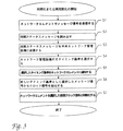
この実施形態の方法は、図3の流れ図として示されている。ネットワークエレメントが同期化されなければならない時、またはネットワークエレメントが誤動作のために基準クロックソースを失い、再同期化しなければならない時に、本方法が実行される。本方法は、次のステップを含む。
【0023】
ステップS1: 同期化すべきネットワークエレメントで、複数のメッセージ信号が受信される。これらのメッセージ信号の1つは、新しいタイミング基準として使用しなければならない。すべての受信されたメッセージ信号は、同期ステータスメッセージを含む。
【0024】
ステップS2: 個々の受信されたメッセージ信号の同期ステータスメッセージが、ネットワークエレメントによって読み出される。
【0025】
ステップS3: ネットワークエレメントは、それぞれの同期ステータスメッセージがどのメッセージ信号から発生しているかに関する情報またはそれぞれのメッセージ信号が受信された入力に関する情報と共に、読み出された同期ステータスメッセージを中央ネットワーク管理設備に送信する。
【0026】
ステップS4: 同期ステータスメッセージ、それぞれの同期ステータスメッセージの発信元に関する受信された情報、および通信ネットワークの構成とコンフィグレーションに関する記憶された情報に基づいて、ネットワーク管理設備は、メッセージ信号の1つを新しいタイミング基準として選択する。
【0027】
ステップS5: ネットワーク管理設備は、行った選択をネットワークエレメントに通知する。
【0028】
ステップS6: ネットワークエレメントは、選択されたメッセージ信号からクロック信号を抽出する。
【0029】
ステップS7: 選択されたメッセージ信号から抽出されたクロック信号を使用して、ネットワークエレメントは、新しい基準クロックソースと同期するために、その内部クロック生成装置を調整する。
【0030】
図4に示されたネットワーク管理設備は、ネットワークエレメントによって送信された同期ステータスメッセージを受信する手段、通信ネットワークの構成とコンフィグレーションに関する情報を記憶する手段、および送信された同期ステータスメッセージと記憶された情報に基づいてネットワークエレメントのタイミング基準を選択する手段とを含む。有利なことに、ネットワーク管理設備は、通信ネットワーク用に指定されたQインタフェースQに接続されたQインタフェース回路I/O、ネットワークエレメントからの選択要求と選択アルゴリズムの中間結果を一時的に記憶する半導体メモリMEM、例えばハードディスクの形式のデータベースを有するデータメモリDATA、制御プログラムによって選択を実行するプロセッサCPU、及びQインタフェース回路I/Oと半導体メモリMEMとデータメモリDATAとプロセッサCPUとを相互接続するバスシステムを含む。データメモリ内に組み込まれたデータベースは、通信ネットワークの構成とコンフィグレーションに関するすべての情報を含む。
【0031】
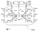
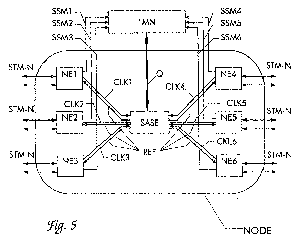
単一のネットワークエレメントの基準クロックソースの選択と同様、本発明は、複数のネットワークエレメントNE1〜NE6と中央ノードクロック生成装置SASEとを含むネットワークノードNODEの基準クロックソースの選択に使用できる。この概略が、図5に第2の実施形態として示されている。ネットワークノードNODEは、6つのネットワークエレメントNE1〜NE6と中央ノードクロック生成装置SASEとを含む。ノードクロック生成装置SASEは、独立した装置としてノード内に設置でき、またはネットワークエレメントの1つ、好ましくはクロスコネクト内に組み込むことができる。ネットワークエレメントNE1〜NE6の各々は、受信したメッセージ信号STM−Nから抽出されたクロック信号CLK1〜CLK6をノードクロック生成装置SASEに送信する。ノードクロック生成装置は、これらのクロック信号の1つと同期し、共通の基準クロック信号REFをすべてのネットワークエレメントに送信する。次いで、ネットワークエレメントNE1〜NE6は、ノードクロック生成装置SASEから受信した基準クロック信号REFと同期する。
【0032】
ネットワークノードNODEは、中央ネットワーク管理設備TMNに接続される。ネットワークエレメントの各々と中央ノードクロック生成装置SASEの両方は、ネットワーク管理設備TMNにリンクされている。ネットワークエレメントは、ノードクロック生成装置SASEに転送されたそれぞれのクロック信号CLK1〜CLK6が抽出された受信メッセージ信号に含まれる同期ステータスメッセージSSM1〜SSM6を、ネットワーク管理設備TMNに送信する。受信した同期ステータスメッセージSSM1〜SSM6と、ネットワーク管理設備TMNに記憶された通信ネットワークの構成とコンフィグレーションに関するデータに基づいて、ネットワーク管理設備TMNは、クロック信号CLK1〜CLK6の1つを、ネットワークノードNODEの基準クロックソースとして選択する。ネットワーク管理設備TMNは、QインタフェースQを介して、中央ノードクロック生成装置SASEにこの選択を通知する。次いで、ノードクロック生成装置SASEは、選択されたクロック信号と同期する。好ましくは、ネットワーク管理設備TMNはまた、選択されたタイミング基準の品質に基づいて、個々のネットワークエレメントNE1〜NE6に、それらの出力で、どの同期ステータスメッセージを送信するかを通知する(表1を参照)。同期ステータスメッセージSSM1〜SSM6の送信に、ネットワークエレメントとネットワーク管理設備TMN間の既存のQインタフェースが使用できる。
【0033】
ネットワークエレメントNE1〜NE6は、好ましくは、アド/ドロップマルチプレクサやクロスコネクトを考える。ネットワークノードは、交換局がその市外トラフィックをルーティングするための同期ディジタル通信ネットワークの交換局に設置されたネットワークエレメントによって構成されてもよい。ノードクロック生成装置SASEは、好ましくは、クロスコネクト内に組み込まれ、さらにクロスコネクトの内部クロック生成装置として使用される。ノードクロック生成装置は、ネットワークノードNODEの一様な基準クロック信号REFの調整および分配を行う。ネットワークエレメント同様、ノードクロック生成装置は、Qインタフェースを介して、ネットワーク管理設備TMNに接続される。ノードクロック生成装置SASEが自立型装置として設計されている場合、本発明の範囲内のネットワークエレメントと考えることもでき、その場合、その入力信号は、ノードの残りのネットワークエレメントから受信されたクロック信号CLK1〜CLK6である。クロック信号は、同期ステータスメッセージもノードクロック生成装置に送信できる2MHzの信号または2Mbの信号である。
【0034】
障害発生時には、1つまたは複数のネットワークエレメントNE1〜NE6が、それらによってノードクロック生成装置SASEに送信中のそれぞれのクロック信号CLK1〜CLK6を停止することが可能である。この機能は「スケルチング(squelching)」と呼ばれる。これがノードクロック生成装置が同期しているクロック信号の場合、新たに選択を行う必要がある。ノードクロック生成装置は、同期している入力信号が障害になったと判断し、ネットワーク管理設備TMNに新しい選択が必要であることを通知する。次いで、ネットワーク管理設備TMNは、本発明による方法を使用して選択を行い、QインタフェースQを介して新しい選択をノードクロック生成装置SASEに通知する。その間、ノードクロック生成装置は、非同期モード(いわゆるホールドオーバモード)に切り替わる。
【図面の簡単な説明】
【図1】同期ディジタル通信ネットワークを示す図である。
【図2】本発明によるネットワークエレメントと、ネットワーク管理設備のブロック図である。
【図3】本発明による方法の流れ図である。
【図4】本発明によるネットワーク管理設備のブロック図である。
【図5】ネットワークノードのブロック図である。
【符号の説明】
BUNDLE 並行伝送経路のバンドル
LINK 光または電気伝送媒体
NE1、NE2、NE3、NE4、NE5 ネットワークエレメント
NET 同期ディジタル通信ネットワーク
PRC 1次基準クロック信号
Q Qインタフェース
REF 共通の基準クロック信号
TMN ネットワーク管理設備[0001]
BACKGROUND OF THE INVENTION
The present invention provides a method for synchronizing network elements in a synchronous digital communication network according to the preamble of
[0002]
[Prior art]
The network elements of a synchronous digital communication network operate according to ITU-T recommendations for synchronous digital hierarchy (SDH) or synchronous optical network (SONET). Add / drop multiplexers, cross-connects, or line multiplexers are understood as “network elements”. It is essential that all network elements operate synchronously during information transmission in such a communication network. This is achieved by mutual synchronization of network elements or master-slave synchronization. At that time, each network element extracts a clock signal from the received message signal, and synchronizes the internal clock generator with this external clock signal. One or more primary clock generators provide a very accurate reference clock for the network.
[0003]
To improve the selection of the message signal as a timing reference, a synchronous status message (SSM) is introduced that is sent as part of the message signal. SSM indicates the quality of the reference clock with which the sending network element is synchronized. The selection of the timing reference is based on SSM as follows. The network element selects the information signal for which the SSM exhibits the highest clock quality as the timing reference. As the SSM, a message “DNU” (“do not use for synchronization”) is defined in which an information signal is to be sent back to the network element selected as the timing reference.
[0004]
Care must be taken to ensure that during synchronization, no timed loop is created, ie that the two network elements do not select each other as a synchronous clock source. In particular, when there are two or more parallel transmission paths between two network elements, there is a high risk of creating a timing loop. Such parallel transmission paths are also referred to as “bundles”. Using only SSM “DNU” does not mean that timing loop generation can be avoided in all possible situations.
[0005]
In order to avoid timing loops, European patent application EP 0723344 proposes to define two classes of interface devices. Only information signals received by the first class interface device can be selected as timing references, while information signals received by the second class interface device must be ignored when selecting the reference clock. I must. An appropriate configuration of the network, for example, by connecting only the first class interface to the second class interface, a timing loop can be avoided. However, this solution is error-prone because it relies on the correct network configuration. In particular, when a bundle of parallel transmission paths exists, an error may enter the configuration, resulting in a timing loop.
[0006]
European patent application EP0849904 proposes another way to avoid timing loops. The selection of the reference clock is performed in the central clock generator of the network node. The selected clock source is communicated to the central network management facility, which central network management facility transmits which SSM at its output to each network element of the node that receives its reference clock from the central clock generator. Instruct. In this way, the SSM “DNU” can be transmitted on all outputs, including the danger of creating a timing loop, thereby effectively preventing the creation of a timing loop. However, this method is complicated because the network management facility must explicitly assign an SSM to each output of each network element. This method also basically depends on the correct network configuration. Furthermore, a plurality of clock interfaces having means for transmitting SSM must be provided between the clock generator and the network element. This increases the complexity and cost of the device and cannot be supplied on currently available network elements.
[0007]
[Problems to be solved by the invention]
The object of the present invention is to provide a method for synchronizing network elements that can be managed by simple technical means, while reducing the risk of generating a timing loop, especially when parallel transmission paths exist. Another object of the present invention is to provide a network element and network management facility suitable for performing this method.
[0008]
[Means for Solving the Problems]
The first stated object is achieved by the features of
[0009]
The invention will become more apparent with reference to the following description of two embodiments with reference to the accompanying drawings.
[0010]
The basic idea of the present invention is to select the timing reference by a central network management facility rather than a network element or central clock generator. Anyway, the existing network management equipment stores all information related to the network configuration and configuration. Another basic idea is that when a network element determines the need for a new selection, for every message signal received at its input, each synchronization message in the message signal is sent to the network management facility and sent Based on the synchronization status message and information on the configuration and configuration of the network, one of the received message signals is selected as a new timing reference and this selection is notified to the network element.
[0011]
As is well known, information transmission between the network element and the central network management facility via the existing Q interface takes seconds to minutes. However, the present invention recognizes that information transmission in a communication network is not significantly degraded if the network element is not immediately resynchronized after its reference clock source is lost or failed. Based. In that case, according to the invention, the network element switches to a free asynchronous mode, the so-called holdover mode, and waits until a new selection is notified by the network management facility. The maximum delay of several minutes caused by information transmission through the Q interface, and latency and processing time in network management equipment are not critical to network operation.
[0012]
Alternatively, after the reference clock source is lost, the network element itself may select a new reference clock source, as is commonly done in the prior art. However, this selection is only temporary for bridging the time until a new reference clock source is selected by the network management facility. When the network management facility communicates a new reference clock source to the network element, the network element switches to the new reference clock source.
[0013]
DETAILED DESCRIPTION OF THE INVENTION
A synchronous digital communication network management facility NET based on a recommendation for synchronous digital hierarchy (SDH) is shown in FIG. The NET consists of several network elements NE1 to NE5 and a central network management facility TMN that are interconnected in both directions by optical or electrical transmission media LINK. The network management facility TMN functions to switch logical connections between network elements, monitor error messages and alarms, and configure the network NET. Furthermore, according to the invention, the network management facility TMN is designed to assign a reference clock source to each network element. In the network element NE1, a very accurate reference clock signal REF from the primary reference clock PRC is supplied to the network.
[0014]
The network elements NE1 to NE5 exchange synchronous message signals configured in the form of synchronous transport modules STM-N via the transmission medium LINK. Synchronization selects the received message signal as a timing reference for each network element, extracts a clock signal from the selected message signal in the network element, and adjusts the network element's internal clock generator to this clock signal. Is achieved. If the link between two network elements fails, resynchronization may be necessary. This requires selecting another received message signal as the new timing reference for the two network elements.
[0015]
The selection of the reference clock source is made by a synchronization status message SSM which is included in the synchronization transport module and transmitted with the synchronization transport module and indicates the respective clock quality of the transmitting network element. In SSM, the messages listed in Table 1 are defined.
[0016]
[Table 1]
[0017]
FIG. 2 shows an embodiment of a network element according to the invention. The network element NE has m inputs for receiving message signals STM-N1 to STM-Nm, respectively. The message signal is configured as a multi-level N (N = 1, 2, 4, 16,...) Synchronous transport module STM-N for the SDH system. Via the Q interface Q, the network element communicates with the central management facility TMN. The block diagram shows only the devices and connections of the network element NE essential for synchronization.
[0018]
For each of the m inputs, the network element NE has interface circuits IN1 to INm. In each interface circuit, clock signals CLK1 to CLKm are extracted from the received message signal. The clock signals CLK1 to CLKm are supplied to the selection device SEL via the respective connections. Further, the interface circuits IN1 to INm read the synchronization status messages SSM1 to SSMm included in the overhead area of the synchronization transport modules STM-N1 to STM-Nm, and pass them to the communication unit COM. The communication unit COM is connected to the network management facility TMN via the Q interface Q. The communication unit COM sends the synchronization status messages SSM1 to SSMm together with information on which of the received message signals each synchronization status message is generated to the network management facility TMN. The network management facility TMN then evaluates the synchronization status messages and selects one of the extracted clock signals CLK1-CLKm as a timing reference based on these messages and stored information regarding the configuration of the communication network. To do. The network management facility TMN notifies the selection to the communication unit COM of the network element NE via the Q interface. The communication unit COM passes the notification to the selection unit SEL, and in response thereto, the selection unit SEL transfers the selected clock signal to the internal clock generation device PLL. The communication unit COM may be, for example, a network element control device, a so-called network element manager.
[0019]
For example, the internal clock generation device PLL can operate in the ITU-T G. A digital phase-locked loop that generates a clock signal having the quality defined in 812 may be used. When the clock signal is transferred to the internal clock generator PLL by the selection unit SEL, the clock signal synchronizes the clock generator PLL. The output signal iCLK of the clock generator PLL is distributed as an internal reference clock to all the output circuits O1 to Ok. As a result, the message signal tSTM-N to be transmitted is generated and transmitted at the internal reference clock speed iCLK.
[0020]
In general, at least some of the interface circuits IN1-INm of the network element NE incorporate timing recovery circuits, so that the clock signals CLK1-CLKm are extracted from the message signals STMN1-STMNm received at these interface circuits. One of these clock signals is then selected as a reference clock by the selection unit SEL according to the selection by the network management facility TMN. Alternatively, only one timing recovery circuit that extracts the reference clock signal from each selected message signal may be provided.
[0021]
In a preferred embodiment, the network management facility also notifies the network element NE via the Q interface Q and the communication unit COM of a synchronization status message tSSM for each of the outputs O1 to Ok. This makes it possible to use SSM “DNU” (“donot use for synchronization”) in all directions with respect to the selected reference clock source, thus not using the synchronization method according to the invention, Network elements that themselves select by SSM can also be operated in a communication network. Alternatively, the network element NE can use the SSM of the received message signal selected as the timing reference provided by the standardization. This is because the network management facility TMN avoids the generation of timing loops by taking into account the information stored there regarding the configuration and configuration of the communication network.
[0022]
The method of this embodiment is shown as a flow diagram in FIG. The method is performed when the network element must be synchronized or when the network element loses the reference clock source due to malfunction and must be resynchronized. The method includes the following steps.
[0023]
Step S1: A plurality of message signals are received at a network element to be synchronized. One of these message signals must be used as a new timing reference. All received message signals include a synchronization status message.
[0024]
Step S2: The synchronization status message of each received message signal is read by the network element.
[0025]
Step S3: The network element sends the read synchronization status message to the central network management facility together with information about which message signal each synchronization status message originates from or information about the input from which each message signal was received. Send.
[0026]
Step S4: Based on the synchronization status message, the received information about the source of each synchronization status message, and the stored information about the configuration and configuration of the communication network, the network management facility updates one of the message signals. Select as timing reference.
[0027]
Step S5: The network management facility notifies the network element of the selection made.
[0028]
Step S6: The network element extracts a clock signal from the selected message signal.
[0029]
Step S7: Using the clock signal extracted from the selected message signal, the network element adjusts its internal clock generator to synchronize with the new reference clock source.
[0030]
The network management facility shown in FIG. 4 is stored with means for receiving synchronization status messages transmitted by network elements, means for storing information about the configuration and configuration of the communication network, and transmitted synchronization status messages. Means for selecting a timing reference for the network element based on the information. Advantageously, the network management facility is a Q interface circuit I / O connected to a Q interface Q designated for a communication network, a semiconductor that temporarily stores an intermediate result of a selection request from a network element and a selection algorithm. Memory MEM, for example, data memory DATA having a database in the form of a hard disk, a processor CPU that executes selection by a control program, and a bus system that interconnects the Q interface circuit I / O, the semiconductor memory MEM, the data memory DATA, and the processor CPU including. The database embedded in the data memory contains all information relating to the configuration and configuration of the communication network.
[0031]
Similar to the selection of the reference clock source of a single network element, the present invention can be used to select the reference clock source of a network node NODE including a plurality of network elements NE1 to NE6 and a central node clock generator SASE. This outline is shown as a second embodiment in FIG. The network node NODE includes six network elements NE1 to NE6 and a central node clock generation device SASE. The node clock generator SASE can be installed in the node as an independent device, or can be incorporated in one of the network elements, preferably in the cross-connect. Each of the network elements NE1 to NE6 transmits the clock signals CLK1 to CLK6 extracted from the received message signal STM-N to the node clock generation device SASE. The node clock generator synchronizes with one of these clock signals and sends a common reference clock signal REF to all network elements. Next, the network elements NE1 to NE6 are synchronized with the reference clock signal REF received from the node clock generator SASE.
[0032]
The network node NODE is connected to the central network management facility TMN. Each of the network elements and the central node clock generator SASE are linked to the network management facility TMN. The network element transmits the synchronization status messages SSM1 to SSM6 included in the received message signal from which the clock signals CLK1 to CLK6 transferred to the node clock generation device SASE are extracted to the network management facility TMN. Based on the received synchronization status messages SSM1 to SSM6 and data relating to the configuration and configuration of the communication network stored in the network management facility TMN, the network management facility TMN sends one of the clock signals CLK1 to CLK6 to the network node NODE. As the reference clock source. The network management facility TMN notifies this selection to the central node clock generator SASE via the Q interface Q. Next, the node clock generation device SASE is synchronized with the selected clock signal. Preferably, the network management facility TMN also informs the individual network elements NE1 to NE6 which synchronization status message to send at their output based on the quality of the selected timing reference (see Table 1). reference). The existing Q interface between the network element and the network management facility TMN can be used for sending the synchronization status messages SSM1 to SSM6.
[0033]
The network elements NE1 to NE6 preferably consider an add / drop multiplexer or a cross-connect. The network node may be constituted by a network element installed at a switching center of a synchronous digital communication network for the switching center to route its toll traffic. The node clock generation device SASE is preferably incorporated in the cross-connect and further used as an internal clock generation device for the cross-connect. The node clock generator adjusts and distributes the uniform reference clock signal REF of the network node NODE. Like the network element, the node clock generator is connected to the network management facility TMN via the Q interface. If the node clock generator SASE is designed as a self-supporting device, it can also be considered as a network element within the scope of the invention, in which case its input signal is a clock signal received from the remaining network elements of the node. CLK1 to CLK6. The clock signal is a 2 MHz signal or a 2 Mb signal that can also send a synchronization status message to the node clock generator.
[0034]
When a failure occurs, one or more network elements NE1 to NE6 can stop the respective clock signals CLK1 to CLK6 that are being transmitted to the node clock generator SASE thereby. This function is called “squelching”. If this is a clock signal with which the node clock generator is synchronized, a new selection must be made. The node clock generator determines that the synchronized input signal has failed and notifies the network management facility TMN that a new selection is required. The network management facility TMN then makes a selection using the method according to the invention and informs the node clock generator SASE of the new selection via the Q interface Q. Meanwhile, the node clock generator switches to the asynchronous mode (so-called holdover mode).
[Brief description of the drawings]
FIG. 1 shows a synchronous digital communication network.
FIG. 2 is a block diagram of a network element and network management facility according to the present invention.
FIG. 3 is a flow chart of a method according to the present invention.
FIG. 4 is a block diagram of a network management facility according to the present invention.
FIG. 5 is a block diagram of a network node.
[Explanation of symbols]
BUNDLE Parallel transmission path bundle LINK Optical or electrical transmission medium NE1, NE2, NE3, NE4, NE5 Network element NET Synchronous digital communication network PRC Primary reference clock signal Q Q interface REF Common reference clock signal TMN Network management equipment
Claims (7)
ネットワークエレメント(NE;NE1〜NE6)の入力(IN1〜INm)で、いくつかの同期ディジタル情報信号(STM−N1〜STM−Nm)を受信するステップと、
同期ディジタル情報信号(STM−N1〜STM−Nm)に含まれるそれぞれの同期ステータスレポート(SSM1〜SSMm)を評価するステップと、
同期ステータスレポート(SSM1〜SSMm)に基づいて、同期ディジタル情報信号の1つをクロック基準として選択するステップと、
選択された同期ディジタル情報信号からクロック信号(CLK1〜CLKm)を抽出するステップと、
ネットワークエレメント(NE;NE1〜NE6)を抽出されたクロック信号と同期化させるステップとを含み、
ネットワークエレメント(NE;NE1〜NE6)が、中央ネットワーク管理装置(TMN)に同期ステータスレポート(SSM1〜SSMm)を送信し、
中央ネットワーク管理装置(TMN)が、同期ステータスレポート(SSM1〜SSMm)と通信ネットワーク(NET)の構成に関する記憶された情報を使用して、同期ディジタル情報信号の1つを選択し、
中央ネットワーク管理装置(TMN)が、ネットワークエレメント(NE;NE1〜NE6)に、同期化のためにネットワークエレメントによって使用されるべき選択された同期ディジタル情報信号を通知することを特徴とする方法。A method for synchronizing network elements (NE; NE1 to NE6) in a synchronous digital communication network (NET),
Receiving several synchronous digital information signals (STM-N1 to STM-Nm) at the inputs (IN1 to INm) of the network elements (NE; NE1 to NE6);
Evaluating each synchronization status report (SSM1 to SSMm) included in the synchronization digital information signals (STM-N1 to STM-Nm);
Selecting one of the synchronous digital information signals as a clock reference based on the synchronization status report (SSM1-SSMm);
Extracting a clock signal (CLK1-CLKm) from the selected synchronous digital information signal;
Synchronizing the network elements (NE; NE1 to NE6) with the extracted clock signal,
The network element (NE; NE1 to NE6) sends a synchronization status report (SSM1 to SSMm) to the central network management device (TMN),
Central network management device (TMN) is, by using the information stored related to the configuration of the synchronization status report (SSM1~SSMm) a communication network (NET), and select one of the synchronous digital information signals,
Method; (NE1~NE6 NE), characterized by notifying the synchronous digital information signal selected to be used by the network element for synchronization central network management device (TMN) is a network element.
ネットワークノード(NODE)が、中央ノードクロック生成装置(SASE)を含み、中央ネットワーク管理装置(TMN)が、ネットワークノード(NODE)のネットワークエレメント(NE1〜NE6)の1つで受信された同期ディジタル情報信号のどれ(STM−N)と同期化すべきかを、個々のネットワークエレメントではなく中央ノードクロック生成装置(SASE)に通知し、
中央ノードクロック生成装置(SASE)が、選択された同期ディジタル情報信号から抽出されたクロック信号(CLK1〜CLK6)と同期し、ネットワークノード(NODE)のネットワークエレメント(NE1〜NE6)に、該ネットワークエレメントが同期する基準クロック信号(REF)を分配する、請求項1に記載の方法。 Several network elements (NE1 to NE6) are arranged in the network node (NODE),
Network node (NODE) comprises a central node clock generator (SASE), central network management device (TMN) is, synchronous digital information received by one of the network elements of the network node (NODE) (NE1~NE6) Inform the central node clock generator (SASE), not individual network elements, of which signal (STM-N) to synchronize,
The central node clock generator (SASE) synchronizes with the clock signals (CLK1 to CLK6) extracted from the selected synchronous digital information signal, and the network elements (NE1 to NE6) of the network node (NODE) are connected to the network elements. 2. The method according to claim 1, wherein the reference clock signal (REF) is synchronized.
情報信号(STM−N1〜STM−Nm)を受信する手段(IN1〜INm)と、
情報信号(STM−N1〜STM−Nm)に含まれるそれぞれの同期ステータスレポート(SSM1〜SSMm)を読み出す手段と、
受信した情報信号(STM−N1〜STM−Nm)の少なくとも1つから少なくとも1つのクロック信号(CLK1〜CLKm)を抽出する手段と、
内部クロック生成装置(PLL)を抽出されたクロック信号(CLK1〜CLKm)に合わせて調整する手段とを含み、
受信した情報信号(STM−N1〜STM−Nm)の1つをクロック基準として選択するために、同期ステータスレポート(SSM1〜SSMm)を読み出した後に中央ネットワーク管理装置(TMN)に送信する手段(COM)と、
行われた選択に関係する中央ネットワーク管理装置(TMN)からの通知を受信する手段(COM)と、
内部クロック生成装置(PLL)を、選択された情報信号から抽出されたクロック信号に合わせて調整する手段と
を特徴とするネットワークエレメント(NE;NE1〜NE6)。A network element (NE; NE1 to NE6) of a synchronous digital communication network (NET),
Means (IN1 to INm) for receiving information signals (STM-N1 to STM-Nm);
Means for reading the respective synchronization status reports (SSM1 to SSMm) included in the information signals (STM-N1 to STM-Nm);
Means for extracting at least one clock signal (CLK1 to CLKm) from at least one of the received information signals (STM-N1 to STM-Nm);
Adjusting the internal clock generator (PLL) in accordance with the extracted clock signals (CLK1 to CLKm),
It means for transmitting one of the received information signals (STM-N1~STM-Nm) in order to be selected as the clock reference, to a central network management device (TMN) after reading the synchronization status report (SSM1~SSMm) ( COM)
A central network management system relating to the selections made means for receiving a notification from the (TMN) (COM),
Internal clock generating device (PLL), a means for adjusting in accordance with the clock signal extracted from the selected information signal
Network element, wherein (NE; NE1~NE6).
ネットワークエレメント(NE;NE1〜NE6)から送信された同期ステータスレポート(SSM1〜SSMm)を受信する手段(I/O)と、
通信ネットワーク(NET)の構成とコンフィグレーションに関する情報を記憶する手段(DATA)と、
送信された同期ステータスレポート(SSM1〜SSMm)と記憶された情報(DATA)を使用して、ネットワークエレメント(NE;NE1〜NE6)についてのクロック基準を選択する手段(CPU)と、
ネットワークエレメント(NE;NE1〜NE6)に対して行われた選択に関係する通知(Q)を送信する手段(I/O)とを特徴とするネットワーク管理装置(TMN)。A network management device (TMN) for controlling network elements (NE; NE1 to NE6) of a synchronous digital communication network (NET),
Means (I / O) for receiving synchronization status reports (SSM1 to SSMm) transmitted from network elements (NE; NE1 to NE6);
Means (DATA) for storing information relating to the configuration and configuration of a communication network (NET);
Using the transmitted synchronization status reports (SSM1~SSMm) and stored information (DATA), Netw network element; means for selecting a clock reference for (NE NE1~NE6) and (CPU),
Netw network element (NE; NE1~NE6) network management device, wherein the means (I / O) to transmit made notification pertaining to select (Q) with respect to (TMN).
Applications Claiming Priority (2)
| Application Number | Priority Date | Filing Date | Title |
|---|---|---|---|
| DE19901588.0 | 1999-01-16 | ||
| DE19901588A DE19901588A1 (en) | 1999-01-16 | 1999-01-16 | Synchronization of a network element in a synchronous digital communication network |
Publications (3)
| Publication Number | Publication Date |
|---|---|
| JP2000216741A JP2000216741A (en) | 2000-08-04 |
| JP2000216741A5 JP2000216741A5 (en) | 2007-01-18 |
| JP4358397B2 true JP4358397B2 (en) | 2009-11-04 |
Family
ID=7894502
Family Applications (1)
| Application Number | Title | Priority Date | Filing Date |
|---|---|---|---|
| JP2000001280A Expired - Fee Related JP4358397B2 (en) | 1999-01-16 | 2000-01-07 | Network element synchronization in synchronous digital communication networks. |
Country Status (5)
| Country | Link |
|---|---|
| US (1) | US6707828B1 (en) |
| EP (1) | EP1021009B1 (en) |
| JP (1) | JP4358397B2 (en) |
| AT (1) | ATE293317T1 (en) |
| DE (2) | DE19901588A1 (en) |
Families Citing this family (22)
| Publication number | Priority date | Publication date | Assignee | Title |
|---|---|---|---|---|
| US20030193924A1 (en) * | 1999-09-10 | 2003-10-16 | Stephan Gehring | Medium access control protocol for centralized wireless network communication management |
| US7023833B1 (en) * | 1999-09-10 | 2006-04-04 | Pulse-Link, Inc. | Baseband wireless network for isochronous communication |
| US20040090983A1 (en) * | 1999-09-10 | 2004-05-13 | Gehring Stephan W. | Apparatus and method for managing variable-sized data slots within a time division multiple access frame |
| DE19943779A1 (en) * | 1999-09-13 | 2001-03-22 | Siemens Ag | Arrangement for synchronizing communication system components coupled via a communication network |
| US7088795B1 (en) * | 1999-11-03 | 2006-08-08 | Pulse-Link, Inc. | Ultra wide band base band receiver |
| US6970448B1 (en) | 2000-06-21 | 2005-11-29 | Pulse-Link, Inc. | Wireless TDMA system and method for network communications |
| US6952456B1 (en) | 2000-06-21 | 2005-10-04 | Pulse-Link, Inc. | Ultra wide band transmitter |
| GB0031839D0 (en) * | 2000-12-29 | 2001-02-14 | Marconi Comm Ltd | A multi-service digital cross-connect |
| US7035246B2 (en) * | 2001-03-13 | 2006-04-25 | Pulse-Link, Inc. | Maintaining a global time reference among a group of networked devices |
| US7012934B1 (en) * | 2001-10-31 | 2006-03-14 | Nortel Networks Limited | Method and apparatus for detecting a network timing loop |
| JP3993508B2 (en) * | 2002-12-02 | 2007-10-17 | 株式会社エヌ・ティ・ティ・ドコモ | Wireless access network system, wireless communication method, synchronization server, and node device |
| KR20060008967A (en) * | 2003-05-07 | 2006-01-27 | 코닌클리케 필립스 일렉트로닉스 엔.브이. | Accident detection system |
| CN101931524A (en) * | 2009-06-25 | 2010-12-29 | 中兴通讯股份有限公司 | A clock source selection method for synchronous digital transmission network |
| US8149881B2 (en) * | 2009-06-26 | 2012-04-03 | Alcatel Lucent | Centralized node clock auto reconfiguration |
| US8203969B2 (en) * | 2009-12-10 | 2012-06-19 | Alcatel Lucent | Network timing topology via network manager |
| EP2434674B1 (en) | 2010-09-24 | 2013-10-30 | Siemens Aktiengesellschaft | Method for synchronising time in a communications network |
| US9762340B1 (en) * | 2012-02-01 | 2017-09-12 | Ciena Corporation | Synchronization timing loop detection systems and methods |
| CN103248445B (en) * | 2012-02-09 | 2018-01-05 | 中兴通讯股份有限公司 | A kind of clock synchronizing method and device |
| CN107453833A (en) * | 2012-09-28 | 2017-12-08 | 华为技术有限公司 | Clock synchronizing method, system and equipment |
| JP6018908B2 (en) * | 2012-12-27 | 2016-11-02 | 株式会社日立製作所 | Synchronous ether machine |
| CN105553596B (en) * | 2015-12-22 | 2018-10-30 | 大唐电信(成都)信息技术有限公司 | A kind of synchronous clock equipment output interface and its type configuration method |
| EP3703241B1 (en) * | 2019-02-26 | 2022-07-13 | Hitachi Energy Switzerland AG | Communication in a converter device |
Family Cites Families (14)
| Publication number | Priority date | Publication date | Assignee | Title |
|---|---|---|---|---|
| DE3833940A1 (en) * | 1988-09-22 | 1990-04-05 | Siemens Ag | METHOD FOR RE-SYNCHRONIZING A SWITCH CENTER IN A TELECOMMUNICATION NETWORK |
| AU8625391A (en) * | 1990-10-22 | 1992-05-20 | Siemens Aktiengesellschaft | Process for transmitting synchronisation signals in a network in the synchronous-digital hierarchy |
| US5271001A (en) * | 1990-10-31 | 1993-12-14 | Nec Corporation | Synchronous terminal station system |
| FI91691C (en) * | 1992-11-09 | 1994-07-25 | Nokia Telecommunications Oy | Hierarchical synchronization method |
| DE4446511A1 (en) * | 1994-12-24 | 1996-06-27 | Sel Alcatel Ag | Synchronous digital message transmission system with hierarchical synchronization network |
| US5790519A (en) * | 1995-10-26 | 1998-08-04 | Dsc Communications Corporation | Broadband digital cross-connect system architecture |
| DE19653261A1 (en) * | 1996-12-20 | 1998-06-25 | Alsthom Cge Alcatel | Synchronous digital message transmission system, control device, network element and central clock generator |
| FI103307B (en) * | 1997-02-11 | 1999-05-31 | Nokia Telecommunications Oy | Communication network synchronization |
| JPH10322379A (en) | 1997-05-21 | 1998-12-04 | Nec Miyagi Ltd | Clock path changeover method |
| AT408593B (en) * | 1997-07-10 | 2002-01-25 | Siemens Ag Oesterreich | METHOD FOR IMPROVING THE DISCLOSURE OF CLOCK QUALITY INFORMATION IN SDH NETWORKS |
| JPH11122207A (en) * | 1997-10-14 | 1999-04-30 | Fujitsu Ltd | Transmission apparatus and signal transmission method in synchronous network |
| US6314114B1 (en) * | 1998-06-23 | 2001-11-06 | Oracle Corporation | Distributed resource management |
| US6317439B1 (en) * | 1999-06-03 | 2001-11-13 | Fujitsu Network Communications, Inc. | Architecture for a SONET line unit including optical transceiver, cross-connect and synchronization subsystem |
| GB2353173B (en) * | 1999-08-10 | 2001-09-19 | Marconi Comm Ltd | Communications system |
-
1999
- 1999-01-16 DE DE19901588A patent/DE19901588A1/en not_active Withdrawn
-
2000
- 2000-01-05 US US09/478,195 patent/US6707828B1/en not_active Expired - Fee Related
- 2000-01-07 JP JP2000001280A patent/JP4358397B2/en not_active Expired - Fee Related
- 2000-01-14 AT AT00440009T patent/ATE293317T1/en not_active IP Right Cessation
- 2000-01-14 EP EP00440009A patent/EP1021009B1/en not_active Expired - Lifetime
- 2000-01-14 DE DE50010021T patent/DE50010021D1/en not_active Expired - Lifetime
Also Published As
| Publication number | Publication date |
|---|---|
| JP2000216741A (en) | 2000-08-04 |
| DE19901588A1 (en) | 2000-07-20 |
| EP1021009A3 (en) | 2004-07-28 |
| EP1021009A2 (en) | 2000-07-19 |
| ATE293317T1 (en) | 2005-04-15 |
| DE50010021D1 (en) | 2005-05-19 |
| EP1021009B1 (en) | 2005-04-13 |
| US6707828B1 (en) | 2004-03-16 |
Similar Documents
| Publication | Publication Date | Title |
|---|---|---|
| JP4358397B2 (en) | Network element synchronization in synchronous digital communication networks. | |
| JP3130989B2 (en) | Method for always synchronizing nodes of a private telecommunications network to the best available clock and private telecommunications network | |
| US5886996A (en) | Synchronous digital communication system with a hierarchical synchronization network | |
| JPH10271100A (en) | Synchronization digital communication system, controller, network element and central clock generator | |
| CN100373848C (en) | Transmission Network Restoration Method Supporting Additional Services | |
| JP3761732B2 (en) | Network synchronization controller | |
| US5706291A (en) | Method and apparatus for connecting two messaging systems having differing synchronizations one of which is message-based | |
| EP4124054A1 (en) | Signal frame processing method and related device | |
| US6560245B1 (en) | Telecommunications system | |
| WO2001028144A1 (en) | Synchronizing device and synchronizing system | |
| WO1995024083A2 (en) | Network arrangement | |
| US7050450B1 (en) | Telecommunications system and method for producing a master clock in the same | |
| JP4181867B2 (en) | Synchronous network establishment method and apparatus | |
| JP3052922B2 (en) | COMMUNICATION TERMINAL DEVICE, ITS OPERATION CLOCK SELECTION METHOD, AND RECORDING MEDIUM RECORDING ITS CONTROL PROGRAM | |
| EP1096709B1 (en) | Communication system | |
| KR100608894B1 (en) | TMD / IP data integrated delivery system and its network synchronization control method | |
| JPH06268624A (en) | Synchronization establishment check method | |
| JPH07107105A (en) | Dependent synchronization control method for duplex loop LAN | |
| JP3409234B2 (en) | Add-drop multiplexer device | |
| JPH11122278A (en) | Network synchronization network system and transmitter-receiver used for it | |
| JP3492558B2 (en) | Ring network system | |
| Crossett et al. | SONET/SDH network synchronization and synchronization sources | |
| JP2004159124A (en) | Data transmission system and transmission device | |
| Kumar | Synchronizing network elements on SONET/SDH rings | |
| JP2006121741A (en) | Transmission apparatus |
Legal Events
| Date | Code | Title | Description |
|---|---|---|---|
| A521 | Request for written amendment filed |
Free format text: JAPANESE INTERMEDIATE CODE: A523 Effective date: 20061127 |
|
| A621 | Written request for application examination |
Free format text: JAPANESE INTERMEDIATE CODE: A621 Effective date: 20061127 |
|
| A977 | Report on retrieval |
Free format text: JAPANESE INTERMEDIATE CODE: A971007 Effective date: 20090710 |
|
| TRDD | Decision of grant or rejection written | ||
| A01 | Written decision to grant a patent or to grant a registration (utility model) |
Free format text: JAPANESE INTERMEDIATE CODE: A01 Effective date: 20090714 |
|
| A01 | Written decision to grant a patent or to grant a registration (utility model) |
Free format text: JAPANESE INTERMEDIATE CODE: A01 |
|
| A61 | First payment of annual fees (during grant procedure) |
Free format text: JAPANESE INTERMEDIATE CODE: A61 Effective date: 20090806 |
|
| FPAY | Renewal fee payment (event date is renewal date of database) |
Free format text: PAYMENT UNTIL: 20120814 Year of fee payment: 3 |
|
| R150 | Certificate of patent or registration of utility model |
Free format text: JAPANESE INTERMEDIATE CODE: R150 |
|
| FPAY | Renewal fee payment (event date is renewal date of database) |
Free format text: PAYMENT UNTIL: 20120814 Year of fee payment: 3 |
|
| FPAY | Renewal fee payment (event date is renewal date of database) |
Free format text: PAYMENT UNTIL: 20130814 Year of fee payment: 4 |
|
| R250 | Receipt of annual fees |
Free format text: JAPANESE INTERMEDIATE CODE: R250 |
|
| R250 | Receipt of annual fees |
Free format text: JAPANESE INTERMEDIATE CODE: R250 |
|
| R250 | Receipt of annual fees |
Free format text: JAPANESE INTERMEDIATE CODE: R250 |
|
| LAPS | Cancellation because of no payment of annual fees |