JP4358162B2 - Gateway device - Google Patents
Gateway device Download PDFInfo
- Publication number
- JP4358162B2 JP4358162B2 JP2005198909A JP2005198909A JP4358162B2 JP 4358162 B2 JP4358162 B2 JP 4358162B2 JP 2005198909 A JP2005198909 A JP 2005198909A JP 2005198909 A JP2005198909 A JP 2005198909A JP 4358162 B2 JP4358162 B2 JP 4358162B2
- Authority
- JP
- Japan
- Prior art keywords
- packet
- network
- signal
- switch
- relays
- Prior art date
- Legal status (The legal status is an assumption and is not a legal conclusion. Google has not performed a legal analysis and makes no representation as to the accuracy of the status listed.)
- Expired - Fee Related
Links
Images


Description
本発明は、例えば回線交換網とIP(Internet Protocol)網とを相互に接続するために用いられるゲートウェイ装置に関する。 The present invention relates to a gateway device used for interconnecting, for example, a circuit switching network and an IP (Internet Protocol) network.
近年になり情報通信ニーズの増大や通信の自由化が進展するにつれ、音声およびデータ通信を含む情報通信サービスが多様化してきている。このような背景から通信サービス分野に新たに参入する事業者(キャリア)も増えてきており、キャリア間のサービス競争が盛んになってきている。新規のキャリアはNCC(New common carrier)と称され、VoIP(Voice over Internet Protocol)などの技術を用いて様々なサービスを提供している。VoIP(ヴォイプ)とはディジタルの音声データをパケット化して伝送することにより、音声系ネットワークとデータ系ネットワークとを統合する技術である。 In recent years, information communication services including voice and data communication have been diversified as information communication needs have increased and communication has been liberalized. Against this background, the number of operators (carriers) newly entering the communication service field is increasing, and service competition among carriers is becoming active. The new carrier is called NCC (New common carrier) and provides various services using a technology such as VoIP (Voice over Internet Protocol). VoIP is a technology that integrates a voice network and a data network by packetizing and transmitting digital voice data.
NCCは、加入者回線を既に持つ特定のキャリアから、交換機などの設備を既定の料金で借り受けることが多い。またNCCの多くは、自らの資金で例えばIP網などの自前の交換ネットワークを構築する。これに、特定キャリアの回線交換網(PSTN:Public Switched Telephone Network)も加えて通信システムが形成され、一般ユーザへのサービスの提供にあたってはこれらの設備が複合的に利用される。下記特許文献1に、IPネットワークを用いたサービスの一例が開示される。
PSTNとIP網とを組み合わせた通信システムを構築するために、ゲートウェイ装置が用いられる。この種の装置は音声データやバイナリデータをIP(Internet Protocol)パケットに変換するIP変換部や、IPパケットをスイッチングするパケットスイッチ部を備える。 A gateway device is used to construct a communication system that combines a PSTN and an IP network. This type of apparatus includes an IP conversion unit that converts voice data and binary data into IP (Internet Protocol) packets, and a packet switch unit that switches IP packets.
ところで、この種の装置において回路故障や回線断などが生じると、カード交換またはケーブル交換が完了するまで回線を使用することができず、復旧に時間がかかる。これを避けるためIP変換部やパケットスイッチ部などを2重化し、信号経路を切り替えるリレーにより待機系と現用系とを切り替えるようにすることが考えられる。しかしながら既存の装置においては全てのトラフィックが現用系に集中するため、処理パフォーマンスが低下することがある。
本発明は上記事情によりなされたもので、その目的は、トラフィックの増加に対するパフォーマンスの低下を軽減したネットワーク装置を提供することにある。
By the way, when a circuit failure or line disconnection occurs in this type of apparatus, the line cannot be used until the card exchange or cable exchange is completed, and it takes time to recover. In order to avoid this, it is conceivable that the IP conversion unit, the packet switch unit, etc. are doubled and the standby system and the active system are switched by a relay for switching the signal path. However, in the existing apparatus, since all traffic is concentrated on the active system, the processing performance may deteriorate.
The present invention has been made in view of the above circumstances, and an object of the present invention is to provide a network device in which a decrease in performance due to an increase in traffic is reduced.
上記目的を達成するために、本願発明の一態様によれば、加入者網と、回線交換網と、パケット通信網との間で相互に通信プロトコルを変換してこれらの網の相互通信を実現するゲートウェイ装置であって、前記加入者網を終端して装置内信号を生成する加入者網インタフェースと、前記回線交換網を終端して前記装置内信号を生成する回線交換網インタフェースと、前記装置内信号を回線交換する交換手段と、この交換手段から前記パケット通信網に向け出力される装置内信号をパケット化する信号変換手段と、この信号変換手段から出力されるパケット信号を前記パケット通信網における宛先に向け経路制御して送出する第1パケットスイッチと、この第1パケットスイッチの予備系として機能する第2パケットスイッチと、前記第1パケットスイッチの障害時には前記信号変換手段から出力されるパケット信号を前記第2パケットスイッチに入力し、前記第1および第2パケットスイッチの無障害時には前記信号変換手段から出力されるパケット信号を前記第1および第2パケットスイッチに入力する切替手段とを具備し、この切替手段は、前記第1パケットスイッチおよび前記第2パケットスイッチの信号入方路および信号出方路に設けられ、前記パケット信号の経路を前記障害時と前記無障害時とで切り替える複数のリレーを備え、これらの複数のリレーはオンとオフの2つの状態を取り、オン状態においてオフ状態よりも多くの電力を消費し、オン状態のリレーの数とオフ状態のリレーの数とを前記障害時と前記無障害時とで同一相当とすべく、前記複数のリレーを前記第1パケットスイッチおよび前記第2パケットスイッチに接続したことを特徴とするゲートウェイ装置が提供される。 In order to achieve the above object, according to one aspect of the present invention, a communication protocol is mutually converted between a subscriber network, a circuit switching network, and a packet communication network to realize mutual communication between these networks. A gateway device that terminates the subscriber network and generates an in-device signal; a circuit-switched network interface that terminates the circuit-switched network and generates the in-device signal; and the device Switching means for circuit-switching the internal signal, signal conversion means for packetizing the internal signal output from the switching means to the packet communication network, and the packet signal output from the signal conversion means for the packet communication network A first packet switch that performs route control toward the destination in the first packet switch, a second packet switch that functions as a backup system for the first packet switch, and the first packet switch. A packet signal output from the signal conversion means is input to the second packet switch when a switch switch fails, and a packet signal output from the signal conversion means is input to the first packet switch when there is no failure in the first and second packet switches. And switching means for inputting to the second packet switch, the switching means being provided in the signal input path and the signal output path of the first packet switch and the second packet switch, and the path of the packet signal A plurality of relays that switch between the failure time and the non-failure time, the plurality of relays take two states of on and off, and in the on state, consumes more power than the off state, and the on state In order to make the number of relays equal to the number of relays in the off state and the number of relays in the off state equal to each other at the time of the failure and the time of the no failure, Gateway device is provided, characterized in that connected to the first packet switch and said second packet switch.
このような手段を講じることにより、パケット通信網に接続されるパケットスイッチは冗長化され、耐障害性能が高められる。しかも、現用系としての第1パケットスイッチに障害が無く、第2パケットスイッチにも障害がない場合には、パケットトラフィックが第1および第2パケットスイッチの両方に振り分けて入力される。これによりトラフィックが一方のパケットスイッチに集中することを防止でき、従ってパフォーマンスの低下を軽減することが可能になる。
しかも、リレーで消費される電力を冗長切替の前後でほぼ同じにすることができる。従って冗長切替の前後において消費電流を安定化でき、装置への負担を軽減することが可能になる。
By taking such means, the packet switch connected to the packet communication network is made redundant, and the fault tolerance performance is improved. In addition, when there is no failure in the first packet switch as the active system and there is no failure in the second packet switch, the packet traffic is distributed and input to both the first and second packet switches. As a result, it is possible to prevent the traffic from being concentrated on one of the packet switches, and thus it is possible to reduce the performance degradation.
Moreover, the power consumed by the relay can be made substantially the same before and after the redundant switching. Therefore, current consumption can be stabilized before and after redundancy switching, and the burden on the apparatus can be reduced.
本発明によれば、トラフィックの増加に対するパフォーマンスの低下を軽減したネットワーク装置を提供することができる。 ADVANTAGE OF THE INVENTION According to this invention, the network apparatus which reduced the performance fall with respect to the increase in traffic can be provided.
[第1の実施形態]
図1は、本発明に係わる通信システムの実施の形態を示すシステム図である。図1において加入者網SNの複数の加入者回線114は、まずゲートウェイ装置1に収容される。ゲートウェイ装置1はIP網DNに接続される。IP網DNはパケット通信網であり、NCCの独自網などとして形成される。またIP網DNとしてインターネットを接続することもできる。
[First Embodiment]
FIG. 1 is a system diagram showing an embodiment of a communication system according to the present invention. In FIG. 1, a plurality of
加入者網SNには、加入者端末5や移動電話システムの基地局CS1、および無線端末PS1などが属する。加入者端末5および基地局CS1は加入者回線114を介してゲートウェイ装置1に接続される。加入者回線114は複数の加入者端末5や無線端末PS1ごとに割り当てられるアクセス回線である。
The subscriber network SN includes a subscriber terminal 5, a mobile phone system base station CS1, and a radio terminal PS1. The subscriber terminal 5 and the base station CS1 are connected to the
ゲートウェイ装置1は、加入者網SNから発せられた信号(音声データや映像、画像データなどのディジタルデータ信号)をIP網DNに送出する。またゲートウェイ装置1は、IP網DNからの加入者網SN内の端末に宛てた信号を加入者網SN内に送出し、当該端末に着信させる。これにより、IP網DNに属する加入者端末7と、加入者端末5および無線端末PS1との間に双方向の通信経路を任意に設定することができる。さらに図1のシステムでは、ネットワーク監視装置MEがIP網DNに設けられる。ネットワーク監視装置MEはIP網DNを介してゲートウェイ装置1と種々の情報を授受し、主にゲートウェイ装置1の運用状態を管理する。
The
図2は、既存の音声通信システムを示すシステムブロック図である。図2において加入者網SNの加入者端末5は、回線交換網XNの交換機3に加入者回線114を介して収容される。交換機3は回線交換網XNに属する設備である。なお図1のシステムと図2のシステムとを組み合わせる場合、ゲートウェイ装置1は交換機3よりも加入者端末側に設けられる。よって加入者網SNと回線交換網XNとの網間接続点は、ゲートウェイ装置1と交換機3との間の接続箇所となる。すなわちゲートウェイ装置1は、加入者網SNと回線交換網XNとの網間接続点よりも加入者網SN側に配置される。また加入者網SNと、回線交換網XNとIP網DNとの通信プロトコルは互いに異なる。
FIG. 2 is a system block diagram showing an existing voice communication system. In FIG. 2, the subscriber terminal 5 of the subscriber network SN is accommodated via the
図3は、図1のゲートウェイ装置1の実施の形態を示す機能ブロック図である。図3において、ゲートウェイ装置1は制御部16と加入者回線インタフェース11,12とを備える。加入者回線インタフェース11は加入者回線114のインタフェース制御を行い、加入者回線インタフェース12は加入者回線115のインタフェース制御を行う。
FIG. 3 is a functional block diagram showing an embodiment of the
すなわち加入者回線インタフェース11は加入者回線114を介して加入者端末や無線基地局を収容し、ISDN(Integrated Service Digital Network)の交換局側インタフェースを提供する。加入者回線インタフェース12は加入者回線115に接続され、ISDNの端末側インタフェースを提供する。なお加入者回線115の通信容量はトラヒックの需要予測に基づいて予め設計される。
That is, the
また制御部16は、時分割スイッチなどの交換部100を備える。交換部100は、IP網DNと加入者回線114のそれぞれとの通信経路を交換接続する。また回線交換網XNがゲートウェイ装置1に接続されている場合には、交換部100は、回線交換網XNおよびIP網DNと加入者回線114のそれぞれとの通信経路を交換接続する。
The
さらに図3のゲートウェイ装置1は、IP変換部14およびパケットスイッチ15を備える。IP変換部14は制御部16とIP網DNとの間に設けられ、網間のプロトコル変換を行う。すなわちIP変換部14は、他の通信網(回線交換網XNなど)を介して与えられる時分割多重信号をIPパケットに変換し、パケットスイッチ15に入力する。IPパケットは宛先IPアドレスに従ってルーティングされ、LAN(Local Area Network)ケーブル117を介してIP網DNに送出される。またIP変換部14は、IP網DNからLANケーブル117およびパケットスイッチ15を介して入力されるIPパケットを時分割多重信号に変換する。
Further, the
なお、図3において加入者回線インタフェース11に収容される加入者回線114の回線収容数と、加入者回線インタフェース12に収容される加入者回線115の回線収容数すなわち通信容量とは、同数とする。または、加入者回線インタフェース11に収容される加入者回線114の回線収容数を、加入者回線インタフェース12に収容される加入者回線115の回線収容数よりも多くする。このようにするとシステムの設計上、有利である。
In FIG. 3, the number of
制御部16はゲートウェイ装置1の全体の制御を行う。つまり、制御部16は加入者回線インタフェース11、加入者回線インタフェース12に対して加入者回線114、加入者回線115の制御を行うよう要求したり、加入者回線インタフェース11、加入者回線インタフェース12が検出した障害を総合的に管理する。
The
ゲートウェイ装置1の制御部16はIP網DN経由でネットワーク監視装置MEに接続される。ネットワーク監視装置MEは制御部16と通信を行い、総合的に管理している情報をネットワーク監視装置ME側で表示することにより、ゲートウェイ装置1を遠隔から監視、管理することができる。
The
図3において、制御部16はIP変換部14およびパケットスイッチ15を介してIP網DNに接続される。加入者回線インタフェース11,12および制御部16はいずれも専用のCPU(Central Processing Unit)およびメモリ(図示せず)を備え、各メモリに記憶されるプログラムに基づくCPUの演算処理により動作する。
In FIG. 3, the
図4は、図3の制御部16およびパケットスイッチ15の冗長構成を示すブロック図である。制御部16およびパケットスイッチ15は、いずれも現用系および予備系に二重化される。パケットスイッチ15は、現用系LANスイッチ151と予備系LANスイッチ152とに二重化される。制御部16は、現用系制御部16aと予備系制御部16bとに二重化される。現用系LANスイッチ151と予備系LANスイッチ152とは、それぞれ自らの駆動状態を示すステータス信号を、ポーリング要求などに応じて現用系制御部16aと予備系制御部16bとに通知する。制御部16はパケットスイッチ15の駆動状態を認識し、その結果に基づく制御信号をリレー制御回路159に与える。リレー制御回路159は、現用系LANスイッチ151と予備系LANスイッチ152との駆動状態に基づいて、パケットスイッチ15内に備わる複数のリレー(後述する)を切替制御するためのリレー制御信号を出力する。
FIG. 4 is a block diagram showing a redundant configuration of the
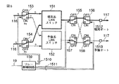
図5は、図3のパケットスイッチ部15の要部構成を示す機能ブロック図である。パケットスイッチ部15は、例えばスイッチングIC(Integrated Circuit)として実現され、IPパケットをOSI参照モデル第3レイヤ以下において処理するLANスイッチを備える。LANスイッチは現用系および予備系を備えて二重化され、現用系LANスイッチに符号151を、予備系LANスイッチに符号152を付与する。
FIG. 5 is a functional block diagram showing a main configuration of the
またパケットスイッチ部15は、シリアルバス116を介して伝送されるIPパケットの伝送経路を現用系LANスイッチ151および予備系LANスイッチ152のいずれかに切り替え、現用系LANスイッチ151と予備系LANスイッチ152との間での冗長切り替えを実現するためのリレー153〜158を備える。リレー153〜158はいずれも2つの接点を有し、オン状態において一方の接点が接続され、オフ状態において他方の接点が接続される。いずれの状態においても電力が消費されるが、オン状態における電力消費量がオフ状態に比べて多いとする。各リレー153〜158は、リレー制御回路159から与えられるリレー制御信号1510,1511によりオンまたはオフのいずれかの状態に切り替えられる。
Further, the
図5において、IP変換部14からのシリアルバス116は2系統に分岐され、それぞれリレー153,154の入力端子に接続される。リレー153のオフ側端子およびリレー154のオン側端子は現用系LANスイッチ151に接続され、リレー153のオン側端子およびリレー154のオフ側端子は予備系LANスイッチ152に接続される。
In FIG. 5, the
現用系LANスイッチ151の出力はリレー155の入力端子に接続され、予備系LANスイッチ152の出力はリレー157の入力端子に接続される。リレー155のオフ側出力端子はリレー156のオフ側入力端子に接続される。リレー155のオン側出力端子はリレー158のオン側入力端子に接続される。リレー157のオン側出力端子はリレー156のオン側入力端子に接続される。リレー157のオフ側出力端子はリレー158のオフ側入力端子に接続される。そして、リレー156の出力端子は現用ポート1512に接続され、リレー158の出力端子は予備ポート1513に接続される。現用ポート1512と予備ポート1513とは、LANケーブル117を介してIP網DNに接続される。
The output of the
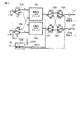
図6は、図5のパケットスイッチ部15の通常状態における信号経路を示す図である。図6において、通常状態すなわち無障害時には、リレー153がオフ、リレー154がオンとなり、シリアルバス116からのIPパケットは全て現用系LANスイッチ151に接続される。また、155〜158のリレーはオフとなり、現用系LANスイッチ151が現用ポート1512およびLANケーブル117を介してIP網DNに接続される。
FIG. 6 is a diagram showing signal paths in the normal state of the
図7は、図6に示される状態から現用系LANスイッチ151に障害が生じた場合の信号経路を示す図である。現用系LANスイッチ151に障害が生じると、図4の現用系LANスイッチ151からのステータス信号が現用系制御部16aに与えられる。これにより現用系制御部16aは障害の発生を認識し、リレー制御回路159にリレー制御情報が発行される。これを受けてリレー制御信号1510によりリレー153がオンされ、リレー154がオフされる。これによりシリアルバス116からのIPパケットは全て予備系LANスイッチ152に接続される。また、リレー制御信号1511によりリレー156,157はいずれもオンされ、これにより予備系LANスイッチ152が現用ポート1512を介してIP網DNに接続される。
FIG. 7 is a diagram showing signal paths when a failure occurs in the active LAN switch 151 from the state shown in FIG. When a failure occurs in the
図8は、図6に示される状態から現用ポート1512に回線障害が生じた場合の信号経路を示す図である。現用ポート1512に回線障害が生じると、現用ポート1512に接続されている現用系LANスイッチ151が障害を検出し、図4の現用系LANスイッチ151からのステータス信号が現用系制御部16aに与えられる。これにより現用系制御部16aは障害の発生を認識し、リレー制御回路159にリレー制御情報が発行される。これを受けてリレー153がオフされるとともにリレー154がオンされ、これによりシリアルバス116からのIPパケットは全て現用系LANスイッチ151に接続される。また、リレー制御信号1511によりリレー156,157がいずれもオンされ、これにより現用系LANスイッチ151が予備ポート1513を介してIP網DNに接続される。
FIG. 8 is a diagram showing a signal path when a line failure occurs in the working
以上のように本実施形態では、パケットスイッチ部15に現用系LANスイッチ151および予備系LANスイッチ152を備えて冗長化し、各LANスイッチ151,152の信号入方路および信号出方路に設けられるリレー153〜158により冗長切り替えを実施できるようにする。これにより障害からの速やかな復旧を実現することができる。各リレー153〜158はオフおよびオンの2つの接続状態を持ち、このうちオン状態において多くの電力を消費するとする。そして、冗長切り替えの前後すなわち通常動作時と障害動作時とにおいて、オン状態に有るリレーの数を同一相当とすべく、各リレー153〜158を現用系LANスイッチ151および予備系LANスイッチ152に接続するようにしている。
As described above, in the present embodiment, the
既存の装置においては、例えば現用系動作時には全てのリレーがオフされ、待機系への切り替えに伴って全てのリレーがオンとなるようになっている。リレーはオン状態において比較的大きな電力を消費するため、全てのリレーがオンされると消費電力が急激に増加し、電源回路などに過大な負荷がかかって最悪の場合には装置破壊に至る虞が有る。 In the existing apparatus, for example, all the relays are turned off during the active system operation, and all the relays are turned on when switching to the standby system. Since relays consume a relatively large amount of power in the on state, the power consumption increases rapidly when all relays are turned on, and there is a risk of overloading the power supply circuit, etc., leading to equipment damage in the worst case. There is.
これに対し第1の実施形態では、IP変換部14に接続されるリレー(リレー153,154)の駆動方向を半分ずつ逆にする構成としているため、図6の状態でのリレーの駆動数をn個とすると、図7の状態でのリレーの駆動数はn+2個、図8の状態でのリレーの駆動数はn+2個となる。よって、冗長切り替えの前後において駆動状態(オン状態)にあるリレーの数はほぼ同じとなる。従って冗長切り替えの前後において消費電流を安定化でき、電源回路などへの負担を軽減できる。特に、nが多くなればなるほどこの効果はより顕著になる。以上のことから、電力消費量を安定化できるとともに障害から速やかに復旧することの可能なゲートウェイ装置を提供することが可能となる。
On the other hand, in the first embodiment, the driving direction of the relays (
[第2の実施形態]
各リレー153〜158は個別にオン/オフ駆動することができ、各リレーのオン/オフ状態の組み合わせは上記の限りではない。以下では、現用系と予備系とを具備することの利点を生かし、LANスイッチへの負荷を軽減することの可能な実施形態を開示する。
[Second Embodiment]
Each of the
図9は、図5のパケットスイッチ部15における信号経路の他の例を示す図である。図9において、現用系LANスイッチ151および予備系LANスイッチ152のいずれにも障害が生じていないとする。このことは図4の制御部16により認識される。この状態において制御部16は、各リレー153〜158を全てオフとする。このようにすることで、LANスイッチ151,152のトラフィック負荷を分散させることができる。またIP変換部14が冗長化されている場合には、各IP変換部14のトラフィック負荷を軽減することもできる。これによりトラフィックの集中を防ぐことができ、負荷を分散してパフォーマンスの低下を軽減することができる。しかも、この状態では全てのリレー153〜158がオフ状態であるので、電力消費量も最低となる。
FIG. 9 is a diagram illustrating another example of a signal path in the
なお、本発明は上記実施形態そのままに限定されるものではなく、実施段階ではその要旨を逸脱しない範囲で構成要素を変形して具体化できる。また、上記実施形態に開示されている複数の構成要素の適宜な組み合わせにより、種々の発明を形成できる。例えば、実施形態に示される全構成要素から幾つかの構成要素を削除してもよい。 Note that the present invention is not limited to the above-described embodiment as it is, and can be embodied by modifying the constituent elements without departing from the scope of the invention in the implementation stage. In addition, various inventions can be formed by appropriately combining a plurality of components disclosed in the embodiment. For example, some components may be deleted from all the components shown in the embodiment.
SN…加入者網、DN…IP網、XN…回線交換網、1…ゲートウェイ装置、CS1…基地局、PS1…無線端末、3…交換機、5〜7…加入者端末、11…加入者回線インタフェース(端末側)、12…加入者回線インタフェース(交換機側)、14…IP変換部、15…パケットスイッチ部、16…制御部、114…加入者回線、115…加入者回線、116…シリアルバス、117…LANケーブル、151…現用系LANスイッチ、152…予備系LANスイッチ、153〜158…リレー、159…リレー制御回路、1512…現用ポート、1513…予備ポート SN ... subscriber network, DN ... IP network, XN ... circuit switching network, 1 ... gateway device, CS1 ... base station, PS1 ... wireless terminal, 3 ... exchange, 5-7 ... subscriber terminal, 11 ... subscriber line interface (Terminal side), 12 ... subscriber line interface (switch side), 14 ... IP conversion unit, 15 ... packet switch unit, 16 ... control unit, 114 ... subscriber line, 115 ... subscriber line, 116 ... serial bus, 117: LAN cable, 151 ... active LAN switch, 152 ... standby LAN switch, 153 to 158 ... relay, 159 ... relay control circuit, 1512 ... active port, 1513 ... spare port
Claims (2)
前記加入者網を終端して装置内信号を生成する加入者網インタフェースと、
前記回線交換網を終端して前記装置内信号を生成する回線交換網インタフェースと、
前記装置内信号を回線交換する交換手段と、
この交換手段から前記パケット通信網に向け出力される装置内信号をパケット化する信号変換手段と、
この信号変換手段から出力されるパケット信号を前記パケット通信網における宛先に向け経路制御して送出する第1パケットスイッチと、
この第1パケットスイッチの予備系として機能する第2パケットスイッチと、
前記第1パケットスイッチの障害時には前記信号変換手段から出力されるパケット信号を前記第2パケットスイッチに入力し、前記第1および第2パケットスイッチの無障害時には前記信号変換手段から出力されるパケット信号を前記第1および第2パケットスイッチに入力する切替手段とを具備し、
この切替手段は、
前記第1パケットスイッチおよび前記第2パケットスイッチの信号入方路に設けられ、前記パケット信号の経路を前記障害時と前記無障害時とで切り替える複数のリレーを備え、
これらの複数のリレーはオンとオフの2つの状態を取り、オン状態においてオフ状態よりも多くの電力を消費し、
オン状態のリレーの数とオフ状態のリレーの数とを前記障害時と前記無障害時とで同一相当とすべく、前記複数のリレーを前記第1パケットスイッチおよび前記第2パケットスイッチに接続したことを特徴とするゲートウェイ装置。 A gateway device that converts communication protocols between a subscriber network, a circuit switching network, and a packet communication network to realize mutual communication between these networks,
A subscriber network interface that terminates the subscriber network and generates an in-device signal;
A circuit switching network interface that terminates the circuit switching network and generates the in-device signal;
Switching means for circuit-switching the in-device signal;
A signal conversion means for packetizing the in-device signal output from the switching means toward the packet communication network;
A first packet switch for routing the packet signal output from the signal conversion means toward the destination in the packet communication network and sending out the packet signal;
A second packet switch functioning as a backup system for the first packet switch;
A packet signal output from the signal conversion means when the first packet switch fails is input to the second packet switch, and a packet signal output from the signal conversion means when the first and second packet switches do not fail Switching means for inputting to the first and second packet switches ,
This switching means is
A plurality of relays that are provided in signal entry paths of the first packet switch and the second packet switch, and switch the path of the packet signal between the failure time and the no-failure time;
These relays take two states, on and off, and consume more power in the on state than in the off state,
The plurality of relays are connected to the first packet switch and the second packet switch so that the number of relays in the on state and the number of relays in the off state are equivalent to each other at the time of the failure and at the time of the no failure. A gateway device characterized by that.
さらに、前記第1パケットスイッチまたは前記第2パケットスイッチから送出されたパケット信号を前記パケット通信網に送出する第1ポートと、A first port for sending a packet signal sent from the first packet switch or the second packet switch to the packet communication network;
前記第1ポートの予備系として機能する第2ポートとをさらに具備することを特徴とする請求項1に記載のゲートウェイ装置。The gateway device according to claim 1, further comprising a second port functioning as a standby system for the first port.
Priority Applications (1)
| Application Number | Priority Date | Filing Date | Title |
|---|---|---|---|
| JP2005198909A JP4358162B2 (en) | 2005-07-07 | 2005-07-07 | Gateway device |
Applications Claiming Priority (1)
| Application Number | Priority Date | Filing Date | Title |
|---|---|---|---|
| JP2005198909A JP4358162B2 (en) | 2005-07-07 | 2005-07-07 | Gateway device |
Publications (2)
| Publication Number | Publication Date |
|---|---|
| JP2007019831A JP2007019831A (en) | 2007-01-25 |
| JP4358162B2 true JP4358162B2 (en) | 2009-11-04 |
Family
ID=37756591
Family Applications (1)
| Application Number | Title | Priority Date | Filing Date |
|---|---|---|---|
| JP2005198909A Expired - Fee Related JP4358162B2 (en) | 2005-07-07 | 2005-07-07 | Gateway device |
Country Status (1)
| Country | Link |
|---|---|
| JP (1) | JP4358162B2 (en) |
Families Citing this family (4)
| Publication number | Priority date | Publication date | Assignee | Title |
|---|---|---|---|---|
| JP4372078B2 (en) | 2005-10-04 | 2009-11-25 | 株式会社東芝 | Gateway device |
| JP4893575B2 (en) * | 2007-10-11 | 2012-03-07 | 日本電気株式会社 | Gateway device, traffic control method, signal processing device, and signal processing program |
| JP5104465B2 (en) | 2008-03-28 | 2012-12-19 | 富士通株式会社 | Transfer device and packet transmission device |
| JP5603375B2 (en) * | 2012-05-18 | 2014-10-08 | Necプラットフォームズ株式会社 | Terminal connection system and method, virtual time division switch, and virtual time division switch program |
-
2005
- 2005-07-07 JP JP2005198909A patent/JP4358162B2/en not_active Expired - Fee Related
Also Published As
| Publication number | Publication date |
|---|---|
| JP2007019831A (en) | 2007-01-25 |
Similar Documents
| Publication | Publication Date | Title |
|---|---|---|
| CN101164307A (en) | Method and gateway equipment for resuming service after switching status of main/standby gateway device | |
| JP4282613B2 (en) | Network connection device | |
| JP4358162B2 (en) | Gateway device | |
| US20110216647A1 (en) | Telephone system, gateway for telephone system, and redundancy switching method | |
| JP4372078B2 (en) | Gateway device | |
| US20030021293A1 (en) | Signaling gateway system and network management method for use in the signaling gateway system | |
| US7827307B2 (en) | Method for fast switchover and recovery of a media gateway | |
| JP4967674B2 (en) | Media service system, media service device, and LAN redundancy method used therefor | |
| CN110677339A (en) | Method and device for protecting redundancy between gateway nodes, gateway equipment and storage medium | |
| WO2014125761A1 (en) | Wireless transmission apparatus, communication system, and communication trouble control method | |
| US7577135B2 (en) | IP telephone system | |
| KR101017502B1 (en) | Duplicate billing system and method in a communication network | |
| JP4579018B2 (en) | IP phone system | |
| JP2006261980A (en) | Network connection device | |
| JP7359681B2 (en) | Line control device and wireless communication system | |
| JP2009232000A (en) | Transmission line terminating apparatus | |
| JP4781697B2 (en) | IP phone system | |
| KR100912005B1 (en) | Gateway system and method for changing redundancy by using automatic protection switching using the same | |
| JP4354357B2 (en) | Packet processing module | |
| JP2007124037A (en) | Telephone exchange and incoming call control method of telephone exchange | |
| JPH06120985A (en) | Packet line backup system | |
| JP3921412B2 (en) | IP phone | |
| KR100894731B1 (en) | Method for changing redundancy by using gateway system | |
| JP5144363B2 (en) | Call control device and telephone system | |
| CN103152262A (en) | Method and equipment for connection establishment |
Legal Events
| Date | Code | Title | Description |
|---|---|---|---|
| A621 | Written request for application examination |
Free format text: JAPANESE INTERMEDIATE CODE: A621 Effective date: 20070319 |
|
| A977 | Report on retrieval |
Free format text: JAPANESE INTERMEDIATE CODE: A971007 Effective date: 20081114 |
|
| A131 | Notification of reasons for refusal |
Free format text: JAPANESE INTERMEDIATE CODE: A131 Effective date: 20081118 |
|
| A521 | Written amendment |
Free format text: JAPANESE INTERMEDIATE CODE: A523 Effective date: 20090119 |
|
| TRDD | Decision of grant or rejection written | ||
| A01 | Written decision to grant a patent or to grant a registration (utility model) |
Free format text: JAPANESE INTERMEDIATE CODE: A01 Effective date: 20090714 |
|
| A01 | Written decision to grant a patent or to grant a registration (utility model) |
Free format text: JAPANESE INTERMEDIATE CODE: A01 |
|
| A61 | First payment of annual fees (during grant procedure) |
Free format text: JAPANESE INTERMEDIATE CODE: A61 Effective date: 20090805 |
|
| FPAY | Renewal fee payment (event date is renewal date of database) |
Free format text: PAYMENT UNTIL: 20120814 Year of fee payment: 3 |
|
| R151 | Written notification of patent or utility model registration |
Ref document number: 4358162 Country of ref document: JP Free format text: JAPANESE INTERMEDIATE CODE: R151 |
|
| FPAY | Renewal fee payment (event date is renewal date of database) |
Free format text: PAYMENT UNTIL: 20120814 Year of fee payment: 3 |
|
| FPAY | Renewal fee payment (event date is renewal date of database) |
Free format text: PAYMENT UNTIL: 20120814 Year of fee payment: 3 |
|
| FPAY | Renewal fee payment (event date is renewal date of database) |
Free format text: PAYMENT UNTIL: 20130814 Year of fee payment: 4 |
|
| LAPS | Cancellation because of no payment of annual fees |