JP4357877B2 - Image forming apparatus and process cartridge - Google Patents
Image forming apparatus and process cartridge Download PDFInfo
- Publication number
- JP4357877B2 JP4357877B2 JP2003156308A JP2003156308A JP4357877B2 JP 4357877 B2 JP4357877 B2 JP 4357877B2 JP 2003156308 A JP2003156308 A JP 2003156308A JP 2003156308 A JP2003156308 A JP 2003156308A JP 4357877 B2 JP4357877 B2 JP 4357877B2
- Authority
- JP
- Japan
- Prior art keywords
- latent image
- image carrier
- transfer
- forming apparatus
- toner
- Prior art date
- Legal status (The legal status is an assumption and is not a legal conclusion. Google has not performed a legal analysis and makes no representation as to the accuracy of the status listed.)
- Expired - Fee Related
Links
Images


Description
【0001】
【発明の属する技術分野】
本発明は、電子写真方式を用いた複写機、ファクシミリ、プリンタに関するものである。
【0002】
【従来の技術】
近年、重合トナーに代表される球形トナーを使用した画像形成装置が上市されている。
重合トナーの様に球形な形状を有するトナーを用いた電子写真記録装置では転写残のトナーをクリーニングするために複雑なシステムを有する場合が多い。例えば従来のクリーニングブレードに加えてファーブラシを当接させたり、そのファーブラシに潤滑剤を塗布させてクリーニングブレードの能力を高めたり、特許文献1に記載のようにクリーニングの前にコロナ放電器を配置してトナーの電荷をそろえクリーニングしやすくしたりする等の方法が実際に使用されている。
【0003】
また、特許文献2に記載のようにクリーニングブレードを排除したものもある。
本発明に使用する画像形成装置は、クリーニングブレードを排除した替わりに一時的保持手段(ブラシローラ、弾性ローラ等)を搭載し、この一時保持手段で転写残トナーの逆帯電トナーを回収し、排出モード時に一時保持手段から感光体上に排出した逆帯電トナーはさらに感光体から感光体に当接する転写手段に排出され、転写手段に設置されているクリーニング機構にて回収される構成をとっている。
しかしながら、このようなシステムの画像形成装置では、長時間使用する事により一時保持手段を通過した逆帯電トナーや、排出モード時に帯電手段と感光体間を通過する逆帯電トナーが機械的な付着力によって帯電手段に堆積し、帯電不良が発生してしまうという問題があった。
【0004】
【特許文献1】
特開平9−330002号公報
【特許文献2】
特開2000−310911号公報
【0005】
【発明が解決しようとする課題】
上記問題点に鑑み、本発明は、帯電手段の汚れを定期的に排出し、帯電不良を防止することが可能な画像形成装置を提供することである。
【0006】
【課題を解決するための手段】
上記課題を解決するために、本発明は、潜像担持体と、帯電部材を潜像担持体表面に接触または近接させている帯電手段と、潜像形成手段と現像手段と、潜像担持体と接触しつつ表面移動する表面移動部材との間に電界を形成して、潜像担持体上に形成されたトナー像を表面移動部材上に転写させる転写手段と、転写後に潜像担持体表面に残留した転写残トナーを潜像担持体から回収して保持し、保持した転写残トナーを潜像担持体表面に排出する一時保持手段と、一時保持手段から排出した転写残トナーを潜像担持体から回収する回収手段とを設ける画像形成装置において、前記画像形成装置は、帯電手段及び現像手段を接地した状態で、一時保持手段に両極性のバイアスを交互に印加し、潜像担持体を両極性に交互に帯電させて、帯電手段上に付着した逆帯電トナーを潜像担持体に排出させ、転写手段に画像転写時とは逆極性の転写バイアスを印加して表面移動部材上に移動させ、表面移動部材に設置しているクリーニング手段で回収し、前記一時保持手段に交互に印加する両極性のバイアスの印加時間を徐々に少なくすることを特徴とする画像形成装置である。
【0007】
本発明は、潜像担持体と、帯電部材を潜像担持体表面に接触または近接させている帯電手段と、潜像形成手段と現像手段と、潜像担持体と接触しつつ表面移動する表面移動部材との間に電界を形成して、潜像担持体上に形成されたトナー像を表面移動部材上に転写させる転写手段と、転写後に潜像担持体表面に残留した転写残トナーを潜像担持体から回収して保持し、保持した転写残トナーを潜像担持体表面に排出する一時保持手段と、一時保持手段から排出した転写残トナーを潜像担持体から回収する回収手段とを設ける画像形成装置において、前記画像形成装置は、帯電手段及び現像手段を接地した状態で、転写手段に両極性のバイアスを交互に印加し、潜像担持体を両極性に交互に帯電させて、帯電手段上に付着した逆帯電トナーを潜像担持体に排出し、前記転写手段に交互に印加するバイアスの印加時間Tは潜像担持体の直径をR,潜像担持体の線速をV、自然数をnとした場合、T=πR/2nVであることを特徴とする画像形成装置である。
【0008】
本発明は、前記いずれかの画像形成装置において、帯電手段上に付着した逆帯電トナーを潜像担持体に排出する時は帯電バイアスを0Vにすることを特徴とする画像形成装置である。
【0009】
本発明は、前記いずれかの画像形成装置において、潜像を担持する潜像担持体と前記転写手段による転写後に潜像担持体表面に残留した転写残トナーとを潜像担持体から回収して保持し、その保持した転写残トナーを潜像担持体表面に排出する一時保持手段を少なくとも一体化するプロセスカートリッジを有することを特徴とする画像形成装置である。
【0010】
本発明は、前記いずれかの画像形成装置において、前記トナーは、体積平均粒径(DV)が3〜8μmの範囲にあり、体積平均粒径(DV)と個数平均粒径(Dn)の比(DV/Dn)で定義される分散度が1.00〜1.40の範囲にあることを特徴とする画像形成装置である。
本発明は、前記いずれかの画像形成装置において、前記トナーは形状係数SF−1で100〜180の範囲にあり、かつ形状係数SF−2で100〜180の範囲に有ることを特徴とする画像形成装置である。
本発明は、前記いずれかの画像形成装置において、前記トナーは紡錘形状であり、長軸と短軸との比(r2/r1)が0.5〜1.0の範囲で、厚さと短軸との比(r3/r2)が0.7〜1.0の範囲であって、長軸r1>短軸r2≧厚さr3の関係を満足することを特徴とする画像形成装置である。
【0011】
本発明は、画像形成装置に着脱可能なプロセスカートリッジであって、少なくとも、潜像担持体と、帯電部材を潜像担持体表面に接触または近接させている帯電手段と、前記転写手段による転写後に潜像担持体表面に残留した転写残トナーを潜像担持体から回収して保持し、保持した転写残トナーを潜像担持体表面に排出する一時保持手段とを一体化するプロセスカートリッジにおいて、帯電手段及び現像手段を接地した状態で、前記一時保持手段に両極性のバイアスを交互に印加し、潜像担持体を両極性に交互に帯電させて、帯電手段上に付着した逆帯電トナーを潜像担持体に排出させ、表面移動部材に設置しているクリーニング手段で回収し、前記一時保持手段に交互に印加する両極性のバイアスの印加時間を徐々に少なくすることを特徴とするプロセスカートリッジである。
【0012】
【発明の実施の形態】
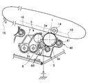
本発明の構成を有する現像装置を図1に基づいて説明する。図1に示すように、ドラム状の感光体1は矢印で示す時計回り方向へ駆動装置(図示せず)によって回転される。感光体1の周囲には、帯電ローラ3aと、露光装置60と、現像装置5と、トナーを一時保持させるブラシローラ41(ブラシローラに限定しない)、転写装置14と、中間転写ベルト10が感光体1の上方に配置されている。また、中間転写ベルト10にはベルトクリーニング装置15が配置されている。
帯電ローラ3aは、感光体1の表面を一様に帯電する。露光装置60は一様に帯電された感光体1の表面にレーザ光を照射して静電潜像を形成する。現像装置5は、トナーを感光体1の表面の静電潜像に与えてトナー画像を形成する。転写装置14は、感光体1の表面のトナー画像を中間転写ベルト10に転写する。中間転写ベルト10に転写されたトナー像は、2次転写装置によって転写紙上にに転写される(図示せず)。ブラシローラ41は、トナー画像の転写後に感光体1の表面に残留している逆帯電残留トナーを、逆帯電トナーと逆のバイアスを印加したブラシローラ41にて保持させる。画像印字時にはこのような帯電工程、露光工程、現像工程、転写工程、が繰り返して実行される。
【0013】
また、画像印字時以外の時にブラシローラ41に確保した逆帯電トナーを、ブラシローラ41に逆帯電トナーと同極性のバイアスを印加する事により逆帯電トナーを電気的に感光体側に排出する。感光体上に排出された逆帯電トナーは転写装置14まで搬送され、画像転写時とは逆バイアスを印加された転写装置14にて中間転写ベルト10上に転写され、ベルトクリーニング装置15にて回収される。
現像装置5は、感光体1に対向する側が開口されている現像容器7と、この現像容器7の内部の感光体1に対向する側に配置されている現像スリーブ5aと、現像容器7に収容されている2成分の現像剤と、この現像剤を撹拌して現像スリーブ5aの表面に現像剤を供給する撹拌部材5bと、現像スリーブ5aの表面に積層(保持)されている現像剤の層厚(高さ)を規制するドクターブレード8とを有している。現像剤は、磁性のキャリアと非磁性のトナーとを混合してなる。現像剤が撹拌部材5bにより撹拌されると、摩擦帯電によりトナーが帯電される。現像スリーブ5aの内部には、マグネット(図示せず)が配置されている。マグネットの磁力により現像剤が現像スリーブ5aの表面に保持される。現像スリーブ5aは矢印方向へ回転され、現像スリーブ5aの表面に保持された現像剤はドクターブレード8により層厚を規制された後に感光体1との間に移動される。現像スリーブ5aの表面に保持されたキャリアに付着したトナーは、現像スリーブ5aと感光体1の静電潜像との間に形成される電界によって感光体1の静電潜像の方向に移動されこの静電潜像に付着される。
【0014】
本使用例は、帯電ローラの汚れに対して厳しい条件である接触帯電方式及びクリーニングブレードの無い構成を用いているが、他の帯電方式及びクリーニングブレードがある構成に関しても本発明は適応できる。
本発明の例では帯電手段として接触方式をとっているが、通常画像出力時には感光体1上の帯電電位が−500Vになる程度のバイアスが印加されている。もし図2の逆帯電トナーT1がブラシローラ41を抜けて帯電ローラ3aの位置まで搬送されると、感光体1上は帯電する前の電位であるから帯電ローラ3aに向けて逆帯電トナーT1が付着する事になる。帯電ローラ3aにトナーが付着すると帯電ローラ3aの抵抗や表面性が変わる為に帯電開始電圧が変化し同じ印加バイアスでも狙った電位が得られなくなり濃度低下や地肌汚れ(かぶり)が発生する事になる。つまり、図2の逆帯電トナーT1を帯電ローラ3aから排出する事が重要である。
【0015】
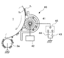
逆帯電トナーT1を帯電ローラから排出する手段を、図3を用いて説明する。逆帯電トナーT1を帯電ローラから排出する手段は画像印字時以外の時に、図3の帯電ローラ3aを接地し、ブラシローラ41に−550Vのバイアスを印加し、感光体表面をマイナスに帯電させ、感光体1と帯電ローラ3aの間に電位差を生じさせる事により、帯電ローラ3aに付着した逆帯電トナーを感光体1上に移動させる。感光体1上に排出された逆帯電トナーは転写装置14まで搬送され、画像転写時とは逆バイアスを印加された転写部にて中間転写ベルト10上に転写されベルトクリーニング装置15にて回収される。この動作を繰り返していると、帯電ローラ3aに付着した逆帯電トナーはマイナスに帯電していき、帯電ローラ3aから感光体1上に移動される逆帯電トナーは徐々に減っていく。そこで、ブラシローラ41に先程とは逆のバイアスの+200Vを印加すると帯電ローラ3a上のトナーは再度感光体上に移動させられる。感光体1上に排出されたトナーは転写装置14まで搬送され、画像転写時と同じバイアスを印加された転写装置14にて中間転写ベルト10上に転写されベルトクリーニング装置15にて回収される。この操作を帯電ローラ3a上のトナーが無くなるまで数回繰り返す。
【0016】
また、この一連の動作中、現像スリーブ5a は接地し駆動も停止させる。
先記したブラシローラ41に印加するブラシバイアスの範囲は、−1200V〜+600Vとする。これは、−1200V以下であると感光体表面電位がマイナス側に高く乗ってしまい、キャリア付着が懸念され、+600V以上であると、感光体表面が疲労し寿命が短くなってしまうからである。
ブラシローラ41に交互にバイアスを印加すると帯電ローラ3a上のトナーは減少していく為、帯電ローラ3aに残っているトナーは短時間で感光体表面電位と同極性に帯電される。その為、帯電ローラ3a上のトナーを逆極性に帯電するまでにかかるバイアス印加時間をT1(マイナス)、T2(プラス)、T3(マイナス)、T3(マイナス)、T4(プラス)、T5(マイナス)・・・とすると、その時間はT1>T2>T3>T4>T5>・・・というように徐々に少なくなる。
また、この発明の利点は帯電ローラ3a上のトナーを排出する為の総時間が短縮されることである。
【0017】
ブラシローラ41の役割を転写装置14にて代用してもよい。利点としては、ブラシローラ41にバイアスを印加するパワーパックがない場合に、ブラシローラ41用のパワーパックを付ける必要がなく、コストアップ及び装置の小型化に優位になる。
転写装置14によって感光体表面を帯電し、帯電ローラ3aから感光体上に排出されたトナーを回収する必要がある。その為、帯電ローラ3aから感光体上に排出されたトナーが、感光体ドラム1と転写装置14との間に到達した時にトナーとは逆極性の転写バイアスをかける必要がある。その為、ブラシローラ41に印加するバイアスの印加時間Tは、図5に示すように感光体1の円周径を偶数分割した時間で極性を反転する必要があり、その関係は、感光体の直径をR、感光体の線速をV、自然数をnとした場合、T=πR/2nVとする。
【0018】
また、帯電部材からの付着物排出時、感光体1が駆動すると同時に、帯電ローラ3aの印加バイアスを0V(アース)にする。この事により、ブラシローラ41や転写装置14によって帯電させられた感光体1との間に電位差を作ることができ、帯電ローラ3a上のトナーを感光体上に移動させることが可能になる。
帯電ローラ3aから感光体1上に排出されたトナーが転写部に到達すると同時にトナーと逆極性の転写バイアスを印加し、感光体上のトナーを中間転写ベルト10に移動させてもよい。
中間転写ベルト10に排出したトナーを中間転写ベルト10に設置しているベルトクリーニング装置15で回収してもよい。さらにそこで回収された排トナーを搬出するための搬出手段(図示せず)も設置されている。このようなシステムを構成する事によって経時的にも異常画像の無い良好な画像が得られる画像形成装置を提供することが可能になる。
【0019】
また、図1に示すように、感光体1、ブラシローラ41、帯電ローラ3a及び現像装置5が一体となったプロセスカートリッジとして交換可能にしてもよい。この様な形態にすることでユーザーの交換作業が容易になり、メンテナンス性が向上するほかに、プロセスカートリッジの交換だけで良好な画像が得られる画像形成装置を提供することが可能になる。
【0020】
次に、本発明の画像形成装置に好適に使用されるトナーについて説明する。
トナーの体積平均粒径は3〜8μmが好ましく、体積平均粒径(Dv)と個数平均粒径(Dn)との比(Dv/Dn)は1.00〜1.40の範囲にあることが好ましい。このような小粒径で粒径分布の狭いトナーでは、トナーの帯電量分布が均一になり、地肌かぶりの少ない高品位な画像を得ることができ、また、転写率を高くすることができる。
【0021】
トナーの形状係数SF−1は100〜180、形状係数SF−2は100〜180の範囲にあることが好ましい。形状係数SF−1は、トナー形状の丸さの割合を示すものであり、下記式(1)で表される。トナーを2次元平面に投影してできる形状の最大長MXLNGの二乗を図形面積AREAで除して、100π/4を乗じた値である。
SF−1={(MXLNG)2/AREA}×(100π/4) ・・・式(1)
SF−1の値が100の場合トナーの形状は真球となり、SF−1の値が大きくなるほど不定形になる。
【0022】
また、形状係数SF−2は、トナーの形状の凹凸の割合を示すものであり、下記式(2)で表される。トナーを2次元平面に投影してできる図形の周長PERIの二乗を図形面積AREAで除して、100π/4を乗じた値である。
SF−2={(PERI)2/AREA}×(100π/4) ・・・式(2)
SF−2の値が100の場合トナー表面に凹凸が存在しなくなり、SF−2の値が大きくなるほどトナー表面の凹凸が顕著になる。
トナーの形状が球形に近くなると、トナーとトナーあるいはトナーと感光体ドラム1との接触合点接触になるために、トナー同士の吸着力は弱くなり従って流動性が高くなり、また、トナーと感光体ドラム1との吸着力も弱くなって、転写率は高くなる。形状係数SF−1、SF−2のいずれかが180を超えると、転写率が低下するため好ましくない。
【0023】
本発明に用いるトナーは、紡錘形状であり、トナーを長軸r1、短軸r2、厚さr3(但し、r1≧r2≧r3とする。)で規定するとき、本発明のトナーは、長軸と短軸との比(r2/r1)が0.5〜1.0で、厚さと短軸との比(r3/r2)が0.7〜1.0の範囲にあることが好ましい。長軸と短軸との比(r2/r1)が0.5未満では、真球形状から離れるためにドット再現性及び転写効率が劣り、高品位な画質が得られなくなる。また、厚さと短軸との比(r3/r2)が0.7未満では、扁平形状に近くなり、球形トナーのような高転写率は得られなくなる。特に、厚さと短軸との比(r3/r2)が1.0では、長軸を回転軸とする回転体となり、トナーの流動性を向上させることができる。
【0024】
【発明の効果】
以上説明したように、本発明によれば、一時保持手段に両極性のバイアスを交互に印加し、潜像担持体を両極性に交互に帯電させて、帯電手段上に付着した付着物を潜像担持体に排出することにより、帯電手段の汚れを定期的に排出し、帯電不良を防止することが可能となる画像形成装置を提供することができる。
【図面の簡単な説明】
【図1】本発明の実施形態の一例である感光体周りの概略構成図である。
【図2】一時保持手段としてのトナー保持装置を示す概略構成図である。
【図3】一時転写ニップ部を示す概略構成図である。
【図4】ブラシローラのバイアスを示す図である。
【符号の説明】
1 感光体ドラム
3 帯電装置
3a 帯電ローラ
5 現像装置
5a 現像スリーブ
5b 攪拌搬送スクリュー
7 現像容器
8 ドクターブレード
10 中間転写ベルト
14 転写装置
15 ベルトクリーニング装置
40 一時保持手段
41 ブラシローラ
60 露光装置[0001]
BACKGROUND OF THE INVENTION
The present invention relates to a copying machine, a facsimile, and a printer using an electrophotographic system.
[0002]
[Prior art]
In recent years, an image forming apparatus using a spherical toner represented by a polymerized toner has been put on the market.
An electrophotographic recording apparatus using a toner having a spherical shape such as a polymerized toner often has a complicated system for cleaning the toner remaining after transfer. For example, in addition to a conventional cleaning blade, a fur brush is brought into contact, or a lubricant is applied to the fur brush to increase the capacity of the cleaning blade. As described in
[0003]
In addition, there is a type in which the cleaning blade is excluded as described in Patent Document 2.
The image forming apparatus used in the present invention is equipped with temporary holding means (brush roller, elastic roller, etc.) instead of removing the cleaning blade, and collects and discharges the reversely charged toner of the transfer residual toner with this temporary holding means. The reversely charged toner discharged from the temporary holding unit to the photosensitive member during the mode is further discharged from the photosensitive member to the transfer unit that contacts the photosensitive member, and is collected by a cleaning mechanism installed in the transfer unit. .
However, in the image forming apparatus of such a system, the reversely charged toner that has passed through the temporary holding unit after being used for a long time or the reversely charged toner that has passed between the charging unit and the photosensitive member in the discharge mode is mechanically attached. As a result, there is a problem that a charging failure occurs due to accumulation on the charging means.
[0004]
[Patent Document 1]
JP-A-9-330002 [Patent Document 2]
Japanese Patent Laid-Open No. 2000-310911
[Problems to be solved by the invention]
In view of the above problems, an object of the present invention is to provide an image forming apparatus capable of periodically discharging dirt on a charging unit and preventing charging failure.
[0006]
[Means for Solving the Problems]
In order to solve the above problems, the present invention provides a latent image carrier, a charging unit in which a charging member is in contact with or close to the surface of the latent image carrier, a latent image forming unit, a developing unit, and a latent image carrier. A transfer means for forming an electric field between the surface moving member and the surface moving member that moves in contact with the surface to transfer the toner image formed on the latent image carrier onto the surface moving member; and a surface of the latent image carrier after the transfer The residual transfer toner remaining on the latent image carrier is collected and held from the latent image carrier, and the temporary transfer means that discharges the retained transfer residual toner to the surface of the latent image carrier, and the residual transfer toner discharged from the temporary holder is latent image carrier. In the image forming apparatus provided with the recovery means for recovering from the body, the image forming apparatus alternately applies a bipolar bias to the temporary holding means while the charging means and the developing means are grounded, Charging hands alternately charged in both polarities The reversely charged toner adhering to the upper surface is discharged to the latent image carrier, and the transfer means is applied with a transfer bias having a polarity opposite to that at the time of image transfer and moved onto the surface moving member. recovered by means, the is an image forming apparatus according to claim least to Rukoto between at bipolar bias applied gradually applied alternately in the temporary holding means.
[0007]
The present invention relates to a latent image carrier, a charging unit in which a charging member is in contact with or close to the surface of the latent image carrier, a latent image forming unit, a developing unit, and a surface that moves while contacting the latent image carrier. An electric field is formed between the transfer member and the transfer member for transferring the toner image formed on the latent image carrier onto the surface transfer member, and transfer residual toner remaining on the surface of the latent image carrier after transfer is latently transferred. Temporary holding means for recovering and holding the transfer residual toner from the image bearing member and discharging the held transfer residual toner to the surface of the latent image carrier; and recovery means for recovering the transfer residual toner discharged from the temporary holding means from the latent image carrier. In the image forming apparatus to be provided, the image forming apparatus applies a bias of both polarities alternately to the transfer unit in a state where the charging unit and the developing unit are grounded, and alternately charges the latent image carrier to both polarities, The reversely charged toner adhering to the charging means Discharged into carrier, the application time T of the bias to be applied alternately to the transfer means the diameter of the image bearing member R, when the linear velocity of the latent image bearing member V, and natural number was n, T = .pi.R / The image forming apparatus is characterized by being 2 nV .
[0008]
The present invention, in any one of the image forming apparatus, Ru image forming apparatus der characterized by a charging bias to 0V when discharging the oppositely charged toner deposited on the charging unit to the latent image bearing member.
[0009]
According to the present invention, in any one of the image forming apparatuses, the latent image carrier that carries a latent image and the transfer residual toner remaining on the surface of the latent image carrier after the transfer by the transfer unit are collected from the latent image carrier. holding an image forming apparatus characterized by having a process cartridge which at least integrating a temporary holding means for discharging the transfer residual toner that held on the surface of the latent image carrier.
[0010]
The present invention, the ratio of the said one Kano image forming apparatus, the toner may have a volume average particle diameter (DV) is in the range of 3 to 8 [mu] m, number average particle diameter and volume average particle diameter (DV) (Dn) The image forming apparatus is characterized in that the degree of dispersion defined by (DV / Dn) is in the range of 1.00 to 1.40.
The present invention, in the any Kano image forming apparatus, the toner image, characterized in that a shape factor SF-1 is in the range of 100 to 180, and a shape factor SF-2 is in the range of 100 to 180 Forming device.
According to the present invention, in any one of the above image forming apparatuses, the toner has a spindle shape, and the ratio of the major axis to the minor axis (r2 / r1) is in the range of 0.5 to 1.0. (R3 / r2) in the range of 0.7 to 1.0, and satisfies the relationship of major axis r1> minor axis r2 ≧ thickness r3.
[0011]
The present invention relates to a process cartridge that can be attached to and detached from an image forming apparatus, and includes at least a latent image carrier, a charging unit that brings a charging member into contact with or close to the surface of the latent image carrier, and after transfer by the transfer unit In a process cartridge in which a transfer residual toner remaining on the surface of the latent image carrier is collected from the latent image carrier and held, and a temporary holding unit that discharges the held transfer residual toner to the surface of the latent image carrier is integrated. With the means and the developing means grounded, a bipolar bias is alternately applied to the temporary holding means to alternately charge the latent image carrier to both polarities, so that the reversely charged toner adhering to the charging means is latent. is discharged to the image bearing member, especially that was collected by the cleaning unit is installed on the surface moving member, gradually reducing the application time of the bipolar bias applied alternately in the temporary holding means A process cartridge to be.
[0012]
DETAILED DESCRIPTION OF THE INVENTION
A developing device having the configuration of the present invention will be described with reference to FIG. As shown in FIG. 1, the drum-
The
[0013]
Further, the reversely charged toner secured on the
The developing
[0014]
In this usage example, the contact charging method and the configuration without the cleaning blade, which are severe conditions against the contamination of the charging roller, are used. However, the present invention can be applied to a configuration with another charging method and a cleaning blade.
In the example of the present invention, the contact method is used as the charging means, but a bias is applied so that the charging potential on the
[0015]
A means for discharging the reversely charged toner T1 from the charging roller will be described with reference to FIG. The means for discharging the reversely charged toner T1 from the charging roller is to ground the charging
[0016]
Further, during this series of operations, the developing
The range of the brush bias applied to the
When a bias is alternately applied to the
An advantage of the present invention is that the total time for discharging the toner on the charging
[0017]
The role of the
It is necessary to charge the surface of the photosensitive member by the
[0018]
In addition, when the adhered material is discharged from the charging member, the applied bias of the charging
The toner discharged on the
The toner discharged to the
[0019]
Further, as shown in FIG. 1, the process cartridge may be replaced as a unit in which the
[0020]
Next, the toner suitably used in the image forming apparatus of the present invention will be described.
The volume average particle diameter of the toner is preferably 3 to 8 μm, and the ratio (Dv / Dn) of the volume average particle diameter (Dv) to the number average particle diameter (Dn) is in the range of 1.00 to 1.40. preferable. With such a toner having a small particle size and a narrow particle size distribution, the toner charge amount distribution is uniform, a high-quality image with little background fogging can be obtained, and the transfer rate can be increased.
[0021]
The toner shape factor SF-1 is preferably in the range of 100 to 180, and the shape factor SF-2 is preferably in the range of 100 to 180. The shape factor SF-1 indicates the ratio of the roundness of the toner shape and is represented by the following formula (1). This is a value obtained by dividing the square of the maximum length MXLNG of the shape formed by projecting the toner on a two-dimensional plane by the figure area AREA and multiplying by 100π / 4.
SF-1 = {(MXLNG) 2 / AREA} × (100π / 4) (1)
When the value of SF-1 is 100, the shape of the toner becomes a true sphere, and becomes larger as the value of SF-1 increases.
[0022]
The shape factor SF-2 indicates the ratio of the unevenness of the toner shape, and is represented by the following formula (2). A value obtained by dividing the square of the perimeter PERI of the figure formed by projecting the toner on the two-dimensional plane by the figure area AREA and multiplying by 100π / 4.
SF-2 = {(PERI) 2 / AREA} × (100π / 4) Expression (2)
When the value of SF-2 is 100, there is no unevenness on the toner surface, and as the value of SF-2 increases, the unevenness of the toner surface becomes more prominent.
When the shape of the toner is close to a sphere, the contact point contact between the toner and the toner or the toner and the
[0023]
The toner used in the present invention has a spindle shape, and when the toner is defined by a major axis r1, a minor axis r2, and a thickness r3 (where r1 ≧ r2 ≧ r3), the toner of the present invention has a major axis. Preferably, the ratio (r2 / r1) to the minor axis is 0.5 to 1.0, and the ratio (r3 / r2) to the minor axis is 0.7 to 1.0. When the ratio of the major axis to the minor axis (r2 / r1) is less than 0.5, the dot reproducibility and transfer efficiency are inferior because of being away from the true spherical shape, and high quality image quality cannot be obtained. On the other hand, if the ratio of thickness to minor axis (r3 / r2) is less than 0.7, the shape is close to a flat shape, and a high transfer rate like a spherical toner cannot be obtained. In particular, when the ratio of the thickness to the minor axis (r3 / r2) is 1.0, the rotating body has a major axis as a rotation axis, and the fluidity of the toner can be improved.
[0024]
【The invention's effect】
As described above, according to the present invention, a bipolar bias is alternately applied to the temporary holding unit, and the latent image carrier is alternately charged to the bipolar, so that the adhered matter adhering to the charging unit is latent. By discharging the toner onto the image carrier, it is possible to provide an image forming apparatus capable of periodically discharging dirt on the charging unit and preventing charging failure.
[Brief description of the drawings]
FIG. 1 is a schematic configuration diagram around a photoconductor as an example of an embodiment of the present invention.
FIG. 2 is a schematic configuration diagram showing a toner holding device as temporary holding means.
FIG. 3 is a schematic configuration diagram illustrating a temporary transfer nip portion.
FIG. 4 is a diagram illustrating a bias of a brush roller.
[Explanation of symbols]
DESCRIPTION OF
Claims (8)
前記画像形成装置は、帯電手段及び現像手段を接地した状態で、一時保持手段に両極性のバイアスを交互に印加し、潜像担持体を両極性に交互に帯電させて、帯電手段上に付着した逆帯電トナーを潜像担持体に排出させ、転写手段に画像転写時とは逆極性の転写バイアスを印加して表面移動部材上に移動させ、表面移動部材に設置しているクリーニング手段で回収し、
前記一時保持手段に交互に印加する両極性のバイアスの印加時間を徐々に少なくする
ことを特徴とする画像形成装置。A latent image carrier, a charging unit that brings a charging member into contact with or close to the surface of the latent image carrier, a latent image forming unit, a developing unit, and a surface moving member that moves on the surface while contacting the latent image carrier. A transfer means for forming an electric field therebetween to transfer the toner image formed on the latent image carrier onto the surface moving member, and transfer residual toner remaining on the surface of the latent image carrier after the transfer from the latent image carrier. An image forming apparatus provided with a temporary holding means for collecting and holding, and discharging the held transfer residual toner to the surface of the latent image carrier, and a collecting means for collecting the transfer residual toner discharged from the temporary holding means from the latent image carrier. In
The image forming apparatus adheres the charging unit and the developing unit to the temporary holding unit by alternately applying a bipolar bias to alternately charge the latent image carrier to the bipolar unit and to adhere to the charging unit. The reversely charged toner is discharged to the latent image carrier, applied to the transfer means by applying a transfer bias having a polarity opposite to that at the time of image transfer, moved onto the surface moving member, and collected by the cleaning means installed on the surface moving member. And
Image forming apparatus, wherein you reduced between upon application of bipolar bias applied alternately in the temporary holding means gradually.
前記画像形成装置は、帯電手段及び現像手段を接地した状態で、転写手段に両極性のバイアスを交互に印加し、潜像担持体を両極性に交互に帯電させて、帯電手段上に付着した逆帯電トナーを潜像担持体に排出し、
前記転写手段に交互に印加するバイアスの印加時間Tは潜像担持体の直径をR、潜像担持体の線速をV、自然数をnとした場合、T=πR/2nVである
ことを特徴とする画像形成装置。A latent image carrier, a charging unit that brings a charging member into contact with or close to the surface of the latent image carrier, a latent image forming unit, a developing unit, and a surface moving member that moves on the surface while contacting the latent image carrier. A transfer means for forming an electric field therebetween to transfer the toner image formed on the latent image carrier onto the surface moving member, and transfer residual toner remaining on the surface of the latent image carrier after the transfer from the latent image carrier. An image forming apparatus provided with a temporary holding means for collecting and holding, and discharging the held transfer residual toner to the surface of the latent image carrier, and a collecting means for collecting the transfer residual toner discharged from the temporary holding means from the latent image carrier. In
In the image forming apparatus, with the charging unit and the developing unit being grounded, a bias of both polarities is alternately applied to the transfer unit, and the latent image carrier is alternately charged to both polarities, and adhered to the charging unit. Discharging the reversely charged toner to the latent image carrier,
The bias application time T applied alternately to the transfer means is T = πR / 2nV, where R is the diameter of the latent image carrier, V is the linear velocity of the latent image carrier, and n is a natural number. An image forming apparatus.
帯電手段上に付着した逆帯電トナーを潜像担持体に排出する時は帯電バイアスを0Vにすることを特徴とする画像形成装置。The image forming apparatus according to claim 1, wherein
An image forming apparatus characterized in that a charging bias is set to 0 V when reversely charged toner adhered on a charging means is discharged to a latent image carrier.
潜像を担持する潜像担持体と前記転写手段による転写後に潜像担持体表面に残留した転写残トナーとを潜像担持体から回収して保持し、その保持した転写残トナーを潜像担持体表面に排出する一時保持手段を少なくとも一体化するプロセスカートリッジを有することを特徴とする画像形成装置。The image forming apparatus according to any one of claims 1 to 3,
The latent image carrier that carries the latent image and the transfer residual toner remaining on the surface of the latent image carrier after the transfer by the transfer means are collected from the latent image carrier and retained, and the retained transfer residual toner is retained on the latent image carrier. An image forming apparatus comprising: a process cartridge for integrating at least a temporary holding unit for discharging onto a body surface.
前記トナーは、体積平均粒径(DV)が3〜8μmの範囲にあり、体積平均粒径(DV)と個数平均粒径(Dn)の比(DV/Dn)で定義される分散度が1.00〜1.40の範囲にあることを特徴とする画像形成装置。The image forming apparatus according to claim 1,
The toner has a volume average particle diameter (DV) in the range of 3 to 8 μm, and a dispersion degree defined by a ratio (DV / Dn) of the volume average particle diameter (DV) to the number average particle diameter (Dn) is 1. An image forming apparatus characterized by being in the range of .00 to 1.40.
前記トナーは形状係数SF−1で100〜180の範囲にあり、かつ形状係数SF−2で100〜180の範囲に有ることを特徴とする画像形成装置。The image forming apparatus according to claim 1,
The image forming apparatus according to claim 1, wherein the toner has a shape factor SF-1 in a range of 100 to 180 and a shape factor SF-2 in a range of 100 to 180.
前記トナーは紡錘形状であり、長軸と短軸との比(r2/r1)が0.5〜1.0の範囲で、厚さと短軸との比(r3/r2)が0.7〜1.0の範囲であって、長軸r1>短軸r2≧厚さr3の関係を満足することを特徴とする画像形成装置。The image forming apparatus according to claim 1,
The toner has a spindle shape, the ratio of major axis to minor axis (r2 / r1) is in the range of 0.5 to 1.0, and the ratio of thickness to minor axis (r3 / r2) is 0.7 to. An image forming apparatus having a range of 1.0 and satisfying a relationship of major axis r1> minor axis r2 ≧ thickness r3.
帯電手段及び現像手段を接地した状態で、前記一時保持手段に両極性のバイアスを交互に印加し、潜像担持体を両極性に交互に帯電させて、帯電手段上に付着した逆帯電トナーを潜像担持体に排出させ、表面移動部材に設置しているクリーニング手段で回収し、
前記一時保持手段に交互に印加する両極性のバイアスの印加時間を徐々に少なくする
ことを特徴とするプロセスカートリッジ。A process cartridge that is detachable from an image forming apparatus, comprising at least a latent image carrier, a charging unit that brings a charging member into contact with or close to the surface of the latent image carrier, and a latent image carrier after transfer by the transfer unit In the process cartridge in which the transfer residual toner remaining on the surface is collected from the latent image carrier and held, and the temporary holding means for discharging the held transfer residual toner to the surface of the latent image carrier is integrated,
While the charging unit and the developing unit are grounded, a bias of both polarities is alternately applied to the temporary holding unit, and the latent image carrier is alternately charged to both polarities, so that the reversely charged toner adhered on the charging unit is removed. Discharged to the latent image carrier and collected by the cleaning means installed on the surface moving member,
A process cartridge, wherein you reduced between upon application of bipolar bias applied alternately in the temporary holding means gradually.
Priority Applications (1)
| Application Number | Priority Date | Filing Date | Title |
|---|---|---|---|
| JP2003156308A JP4357877B2 (en) | 2003-06-02 | 2003-06-02 | Image forming apparatus and process cartridge |
Applications Claiming Priority (1)
| Application Number | Priority Date | Filing Date | Title |
|---|---|---|---|
| JP2003156308A JP4357877B2 (en) | 2003-06-02 | 2003-06-02 | Image forming apparatus and process cartridge |
Publications (2)
| Publication Number | Publication Date |
|---|---|
| JP2004361450A JP2004361450A (en) | 2004-12-24 |
| JP4357877B2 true JP4357877B2 (en) | 2009-11-04 |
Family
ID=34050429
Family Applications (1)
| Application Number | Title | Priority Date | Filing Date |
|---|---|---|---|
| JP2003156308A Expired - Fee Related JP4357877B2 (en) | 2003-06-02 | 2003-06-02 | Image forming apparatus and process cartridge |
Country Status (1)
| Country | Link |
|---|---|
| JP (1) | JP4357877B2 (en) |
Families Citing this family (2)
| Publication number | Priority date | Publication date | Assignee | Title |
|---|---|---|---|---|
| JP2006301463A (en) * | 2005-04-22 | 2006-11-02 | Ricoh Co Ltd | Developing device, process cartridge, image forming apparatus, and toner |
| JP4878221B2 (en) * | 2006-06-09 | 2012-02-15 | キヤノン株式会社 | Image forming apparatus |
-
2003
- 2003-06-02 JP JP2003156308A patent/JP4357877B2/en not_active Expired - Fee Related
Also Published As
| Publication number | Publication date |
|---|---|
| JP2004361450A (en) | 2004-12-24 |
Similar Documents
| Publication | Publication Date | Title |
|---|---|---|
| US6807384B2 (en) | Image forming apparatus | |
| JPH05346751A (en) | Image forming device | |
| JP4357877B2 (en) | Image forming apparatus and process cartridge | |
| JPH09251264A (en) | Cleaner and process cartridge equipped therewith and image forming device using the same | |
| US6640072B2 (en) | Image forming apparatus including an image bearing member and a charging member featuring a controlled peripheral velocity difference therebetween during charging | |
| JPH10247036A (en) | Image forming device and processing cartridge | |
| JPH07210053A (en) | Cleaning device for electrophotographic device | |
| JP2004117599A (en) | Image forming apparatus | |
| JP2992421B2 (en) | Image forming device | |
| JP2005189594A (en) | Cleaning apparatus, process cartridge, and image forming apparatus | |
| JP2610454B2 (en) | Developing device | |
| JP3129425B2 (en) | Filming removal device for latent image carrier | |
| JP4429660B2 (en) | Image forming apparatus, process cartridge | |
| JP2009098498A (en) | Image forming device | |
| JP2872775B2 (en) | Magnetic brush cleaning device | |
| JP4593097B2 (en) | Cleaning device, process cartridge, and color image forming apparatus having the same | |
| JP2980654B2 (en) | Latent image carrier cleaning and filming removal device | |
| JP2596261B2 (en) | Image forming apparatus and image forming method | |
| JPH10333523A (en) | Image forming device | |
| JPH11305624A (en) | Electrophotographic recorder | |
| JPH07281508A (en) | Image-forming device | |
| JP3862426B2 (en) | Image forming apparatus | |
| KR100465218B1 (en) | Developing apparatus for Image forming apparatus | |
| JPH0746936Y2 (en) | Image forming device | |
| JP2001056628A (en) | Cleaning device |
Legal Events
| Date | Code | Title | Description |
|---|---|---|---|
| A621 | Written request for application examination |
Free format text: JAPANESE INTERMEDIATE CODE: A621 Effective date: 20050712 |
|
| A977 | Report on retrieval |
Free format text: JAPANESE INTERMEDIATE CODE: A971007 Effective date: 20081113 |
|
| A131 | Notification of reasons for refusal |
Free format text: JAPANESE INTERMEDIATE CODE: A131 Effective date: 20081118 |
|
| A521 | Written amendment |
Free format text: JAPANESE INTERMEDIATE CODE: A523 Effective date: 20090119 |
|
| A131 | Notification of reasons for refusal |
Free format text: JAPANESE INTERMEDIATE CODE: A131 Effective date: 20090303 |
|
| A521 | Written amendment |
Free format text: JAPANESE INTERMEDIATE CODE: A523 Effective date: 20090408 |
|
| A131 | Notification of reasons for refusal |
Free format text: JAPANESE INTERMEDIATE CODE: A131 Effective date: 20090602 |
|
| A521 | Written amendment |
Free format text: JAPANESE INTERMEDIATE CODE: A523 Effective date: 20090622 |
|
| TRDD | Decision of grant or rejection written | ||
| A01 | Written decision to grant a patent or to grant a registration (utility model) |
Free format text: JAPANESE INTERMEDIATE CODE: A01 Effective date: 20090804 |
|
| A01 | Written decision to grant a patent or to grant a registration (utility model) |
Free format text: JAPANESE INTERMEDIATE CODE: A01 |
|
| A61 | First payment of annual fees (during grant procedure) |
Free format text: JAPANESE INTERMEDIATE CODE: A61 Effective date: 20090805 |
|
| FPAY | Renewal fee payment (event date is renewal date of database) |
Free format text: PAYMENT UNTIL: 20120814 Year of fee payment: 3 |
|
| R150 | Certificate of patent or registration of utility model |
Free format text: JAPANESE INTERMEDIATE CODE: R150 |
|
| FPAY | Renewal fee payment (event date is renewal date of database) |
Free format text: PAYMENT UNTIL: 20120814 Year of fee payment: 3 |
|
| FPAY | Renewal fee payment (event date is renewal date of database) |
Free format text: PAYMENT UNTIL: 20130814 Year of fee payment: 4 |
|
| LAPS | Cancellation because of no payment of annual fees |