JP4355498B2 - Movable heat exchange catheter system - Google Patents
Movable heat exchange catheter system Download PDFInfo
- Publication number
- JP4355498B2 JP4355498B2 JP2002592846A JP2002592846A JP4355498B2 JP 4355498 B2 JP4355498 B2 JP 4355498B2 JP 2002592846 A JP2002592846 A JP 2002592846A JP 2002592846 A JP2002592846 A JP 2002592846A JP 4355498 B2 JP4355498 B2 JP 4355498B2
- Authority
- JP
- Japan
- Prior art keywords
- heat exchange
- catheter
- blood
- wire
- catheter body
- Prior art date
- Legal status (The legal status is an assumption and is not a legal conclusion. Google has not performed a legal analysis and makes no representation as to the accuracy of the status listed.)
- Expired - Fee Related
Links
Images


Classifications
-
- A—HUMAN NECESSITIES
- A61—MEDICAL OR VETERINARY SCIENCE; HYGIENE
- A61F—FILTERS IMPLANTABLE INTO BLOOD VESSELS; PROSTHESES; DEVICES PROVIDING PATENCY TO, OR PREVENTING COLLAPSING OF, TUBULAR STRUCTURES OF THE BODY, e.g. STENTS; ORTHOPAEDIC, NURSING OR CONTRACEPTIVE DEVICES; FOMENTATION; TREATMENT OR PROTECTION OF EYES OR EARS; BANDAGES, DRESSINGS OR ABSORBENT PADS; FIRST-AID KITS
- A61F7/00—Heating or cooling appliances for medical or therapeutic treatment of the human body
- A61F7/12—Devices for heating or cooling internal body cavities
- A61F7/123—Devices for heating or cooling internal body cavities using a flexible balloon containing the thermal element
-
- A—HUMAN NECESSITIES
- A61—MEDICAL OR VETERINARY SCIENCE; HYGIENE
- A61F—FILTERS IMPLANTABLE INTO BLOOD VESSELS; PROSTHESES; DEVICES PROVIDING PATENCY TO, OR PREVENTING COLLAPSING OF, TUBULAR STRUCTURES OF THE BODY, e.g. STENTS; ORTHOPAEDIC, NURSING OR CONTRACEPTIVE DEVICES; FOMENTATION; TREATMENT OR PROTECTION OF EYES OR EARS; BANDAGES, DRESSINGS OR ABSORBENT PADS; FIRST-AID KITS
- A61F7/00—Heating or cooling appliances for medical or therapeutic treatment of the human body
- A61F2007/0054—Heating or cooling appliances for medical or therapeutic treatment of the human body with a closed fluid circuit, e.g. hot water
-
- A—HUMAN NECESSITIES
- A61—MEDICAL OR VETERINARY SCIENCE; HYGIENE
- A61F—FILTERS IMPLANTABLE INTO BLOOD VESSELS; PROSTHESES; DEVICES PROVIDING PATENCY TO, OR PREVENTING COLLAPSING OF, TUBULAR STRUCTURES OF THE BODY, e.g. STENTS; ORTHOPAEDIC, NURSING OR CONTRACEPTIVE DEVICES; FOMENTATION; TREATMENT OR PROTECTION OF EYES OR EARS; BANDAGES, DRESSINGS OR ABSORBENT PADS; FIRST-AID KITS
- A61F7/00—Heating or cooling appliances for medical or therapeutic treatment of the human body
- A61F7/12—Devices for heating or cooling internal body cavities
- A61F2007/126—Devices for heating or cooling internal body cavities for invasive application, e.g. for introducing into blood vessels
-
- Y—GENERAL TAGGING OF NEW TECHNOLOGICAL DEVELOPMENTS; GENERAL TAGGING OF CROSS-SECTIONAL TECHNOLOGIES SPANNING OVER SEVERAL SECTIONS OF THE IPC; TECHNICAL SUBJECTS COVERED BY FORMER USPC CROSS-REFERENCE ART COLLECTIONS [XRACs] AND DIGESTS
- Y02—TECHNOLOGIES OR APPLICATIONS FOR MITIGATION OR ADAPTATION AGAINST CLIMATE CHANGE
- Y02P—CLIMATE CHANGE MITIGATION TECHNOLOGIES IN THE PRODUCTION OR PROCESSING OF GOODS
- Y02P20/00—Technologies relating to chemical industry
- Y02P20/141—Feedstock
-
- Y—GENERAL TAGGING OF NEW TECHNOLOGICAL DEVELOPMENTS; GENERAL TAGGING OF CROSS-SECTIONAL TECHNOLOGIES SPANNING OVER SEVERAL SECTIONS OF THE IPC; TECHNICAL SUBJECTS COVERED BY FORMER USPC CROSS-REFERENCE ART COLLECTIONS [XRACs] AND DIGESTS
- Y10—TECHNICAL SUBJECTS COVERED BY FORMER USPC
- Y10T—TECHNICAL SUBJECTS COVERED BY FORMER US CLASSIFICATION
- Y10T428/00—Stock material or miscellaneous articles
- Y10T428/24—Structurally defined web or sheet [e.g., overall dimension, etc.]
- Y10T428/24942—Structurally defined web or sheet [e.g., overall dimension, etc.] including components having same physical characteristic in differing degree
Abstract
Description
本発明は、患者の体内温度を調整もしくは変更すべく構成された熱交換カテーテルに関し、特に、熱交換面と同面上を通過する血液との間の熱伝達を増加させるべく、十分な動作を発生させるために熱交換面に動作源を備えた血管内熱交換カテーテルシステムに関する。 The present invention relates to a heat exchange catheter configured to adjust or change a patient's body temperature, and in particular, sufficient operation to increase heat transfer between the heat exchange surface and blood passing through the same surface. The present invention relates to an intravascular heat exchange catheter system having an operating source on a heat exchange surface for generation.
通常は、人体の体温調整システムは、体温を約37°C(華氏98.6度)程度に保ち、これを正常体温と称している。
様々な理由により、人は、低体温と呼ばれる正常体温以下の体温、もしくは高体温と呼ばれる正常体温以上の体温を発生させる。低体温および高体温は概して有害であり、症状が深刻な場合には、患者は治療を受け、症状を回復させて正常体温に戻す。治療を要するほどの急激な低体温は、患者が極端に寒い環境に置かれたり、患者の体温調整機能が、怪我、病気または麻酔により低下している時に起こり得る。例えば、このような低体温は、外傷を受けた患者や、手術を受ける患者の合併症として起きることがある。同様に、高体温は、極端に暑い環境に置かれた場合や、怪我、病気または麻酔の合併症により起こり得る。
Usually, the body temperature regulation system of the human body keeps the body temperature at about 37 ° C. (98.6 degrees Fahrenheit), which is called normal body temperature.
For various reasons, a person generates a body temperature below normal body temperature called hypothermia, or a body temperature above normal body temperature called hyperthermia. Hypothermia and hyperthermia are generally detrimental, and if symptoms are severe, the patient is treated and the symptoms are restored to normal body temperature. Sudden hypothermia that may require treatment can occur when the patient is placed in an extremely cold environment or when the patient's thermoregulatory function is reduced due to injury, illness, or anesthesia. For example, such hypothermia can occur as a complication of a patient who has undergone trauma or undergoing surgery. Similarly, hyperthermia can occur when placed in an extremely hot environment or due to injury, illness or anesthesia complications.
しかしながら、他の特定の状況においては、高体温および特に低体温が望ましい場合があり、意図的に引き起こされる場合がある。例えば、低体温は、概して神経防護作用であると認識されており、それ故、虚血性脳卒中もしくは出血性脳卒中、心停止、脳内出血もしくは頭蓋内出血ならびに頭部および脊髄外傷などによる血液不足の治療と併せて導入される。上記の各疾患において、神経組織の損傷が、虚血、脳圧の上昇、浮腫もしくは他の症状により引き起こされて、脳機能障害および恒久的な神経機能障害を生じることがある。 However, in other specific situations, hyperthermia and particularly hypothermia may be desirable and may be caused intentionally. For example, hypothermia is generally recognized as a neuroprotective effect, and therefore treatment of blood deficits such as ischemic or hemorrhagic stroke, cardiac arrest, intracerebral or intracranial hemorrhage, and head and spinal cord trauma. Also introduced. In each of the above diseases, nerve tissue damage can be caused by ischemia, increased brain pressure, edema or other symptoms, resulting in brain dysfunction and permanent neurological dysfunction.
低体温が神経防護作用である他の例としては、心筋梗塞および心臓手術における心停止の時間、動脈瘤の治療手術、血管動脈瘤の治療、脊髄手術、および心臓、脳、脊髄への輸血が一時的に遮断され得るような心臓バイパス手術、または他の手術などで脳、心臓または脊髄に虚血を引き起こすようなリスクを患者が負う治療がある。 Other examples where hypothermia is a neuroprotective effect include cardiac arrest time in myocardial infarction and cardiac surgery, aneurysm treatment, vascular aneurysm treatment, spinal surgery, and blood transfusion to the heart, brain, and spinal cord There are treatments in which the patient bears the risk of causing ischemia in the brain, heart or spinal cord, such as cardiac bypass surgery, which may be temporarily blocked, or other surgery.
低体温療法はまた、心筋梗塞(MI)の間もしくは後の神経組織および心筋組織両方を保護する治療としても有効であることが判ってきた。
偶発的な低体温症の治療であれ、低体温症から回復させる処置であれ、暖めるための表面的な方法としては、患者を暖めた毛布でくるんだり、温浴させたりすることである。低体温症がさほど深刻でない場合や、低体温症から緊急に回復させる必要がない場合は、これらの方法で十分である。しかしながら、体表面の毛細血管床の血管収縮、および皮膚に血液を送らない動静脈短絡などの正常な体温調整機能の反応により、体表面をゆっくり暖める必要がある。
Hypothermia has also proven effective as a treatment to protect both neural and myocardial tissue during or after myocardial infarction (MI).
Whether it is treatment of accidental hypothermia or treatment to recover from hypothermia, the superficial method for warming is to wrap the patient in a warm blanket or bath. These methods are sufficient when hypothermia is less severe or when there is no need to urgently recover from hypothermia. However, it is necessary to warm the body surface slowly by the reaction of the normal body temperature regulation function such as the vasoconstriction of the capillary bed on the body surface and the arteriovenous short circuit that does not send blood to the skin.
低体温が望ましい場合、例えば患者が卒中を起こした場合、患者を冷やした毛布でくるんだり、アルコールで体を擦ったりして体温を下げる試みがなされることがある。体表面を冷やして低体温を起こすこれらの試みは、冷やした毛布やアルコールを患者の皮膚に使用することにより体温調整機能の反応を招くため、緩慢で非効率的なものである。さらに、体表面を冷やすことは、覚醒している患者にとっても非常に不快なものである。さらに問題となる要素として、患者の体が震えて、おそらく促進性グロブリンもしくはそれ以上の因子により、体内から発生する熱量を増加させる。このために、患者の体温の低下をさらに困難にしている。体の震えは、患者の不快感を増大させ、時には体表面の冷却が困難になるほどである。 When hypothermia is desired, for example, when a patient has a stroke, attempts may be made to lower the body temperature by wrapping the patient in a chilled blanket or rubbing the body with alcohol. These attempts to cool the body surface and cause hypothermia are slow and inefficient, because the use of a chilled blanket or alcohol on the patient's skin causes a reaction of the body temperature regulation function. Furthermore, cooling the body surface is very uncomfortable for awake patients. A further problem is that the patient's body shakes, increasing the amount of heat generated from the body, possibly due to stimulating globulins or higher factors. This makes it more difficult to lower the patient's body temperature. Tremors increase patient discomfort and sometimes make it difficult to cool the body surface.
暖めたあるいは冷やした呼吸ガス、暖めた輸液を使用して、患者を暖めたり冷やしたりすることがある。患者を傷つけることなく使用できる輸液量およびガスまたは輸液の温度制限により、加えるあるいは取り除く熱量が制限されるので、ゆっくりとあまり制御しないで処置を行う必要がある。 The patient may be warmed or cooled using warm or cold breathing gas or warm infusion. Because the volume of infusion that can be used without damaging the patient and the temperature limit of the gas or infusion limits the amount of heat that is added or removed, treatment must be performed slowly and with little control.
極めて侵襲的な方法を用いて患者の体温を調整することがあり、同方法において、患者の血液は(下大静脈などの静脈に取り付けた)カニューレを介して外部ポンプに送られ、その後患者の体内に送り返される。患者から取り出された血液は、外部で加熱もしくは冷却されて体内に送り返される。そのようなバイパス処置の例としては、心臓切開手術においてしばしば使用される心肺バイパスシステム(CPB)がある。このバイパス方法は、一旦開始すると、迅速かつ効果的に患者の血液に熱を加え、また熱を取り除いて患者の体温を調整する。しかしながら、同方法は、複雑な機器の使用や高度に熟練した複数の操作者を必要とし、外科的治療においてのみ利用可能であり、その複雑さ故に非常に費用がかかり、行うまでに長い時間を要する極めて侵襲的な治療行為を伴うという点において不都合を生じる。実際に、この方法は、患者の胸部を切開手術した後でなければ行えず、胸部を閉じるまでは再度暖めることができない。さらに、このようなバイパス方法は、血液を機械的に送る必要があり、これは血液にとって極めて危険であり、赤血球溶血などを起こすことがある。このため、4時間を越えるバイパスの使用は望ましくなく、長時間の体温調整を必要とするこの技術の使用が制限される。 The patient's body temperature may be adjusted using a highly invasive method, in which the patient's blood is pumped to an external pump via a cannula (attached to a vein such as the inferior vena cava) and then the patient's blood Sent back into the body. The blood removed from the patient is heated or cooled externally and sent back into the body. An example of such a bypass procedure is the cardiopulmonary bypass system (CPB) often used in open heart surgery. Once started, this bypass method quickly and effectively applies heat to the patient's blood and removes the heat to adjust the patient's body temperature. However, this method requires the use of complex equipment and multiple highly skilled operators and can only be used in surgical treatments, and because of its complexity, it is very expensive and takes a long time to perform. This is disadvantageous in that it involves a very invasive therapeutic action. In fact, this method can only be performed after the patient's chest has been opened and cannot be warmed again until the chest is closed. In addition, such bypass methods require blood to be sent mechanically, which is extremely dangerous for blood and can cause red blood cell hemolysis and the like. For this reason, the use of a bypass for more than 4 hours is undesirable and limits the use of this technique which requires prolonged body temperature regulation.
外部のポンプにより機械的に血液を送る必要のない他の方法として、患者の血流内に配置した熱交換カテーテルにより、低体温あるいは高体温を治療もしくは起こす方法は、ギンズバーグ(Ginsburg)に付与された米国特許第5486208号に記載されており、その内容は参照により本願に組み込まれる。同特許は、熱交換領域を有する熱交換カテーテルを血管内に挿入し、熱交換領域と患者の体温に影響を及ぼす血液との間で熱交換を行うことにより、血液に熱を加えたり、血液から熱を取り除いて体温を調整する方法を開示している。開示された一方法には、バルーンからなる熱交換領域を有するカテーテルを患者の血管内に挿入し、バルーンが血液に接触している間に、バルーンを介して加熱もしくは冷却した熱交換流体を循環させる方法が含まれる。 As another method that does not require blood to be pumped mechanically by an external pump, a method for treating or causing hypothermia or hyperthermia with a heat exchange catheter placed in the patient's bloodstream is given to Ginsburg. U.S. Pat. No. 5,486,208, the contents of which are incorporated herein by reference. In this patent, a heat exchange catheter having a heat exchange region is inserted into a blood vessel, and heat is exchanged between the heat exchange region and blood that affects the body temperature of the patient. Discloses a method of adjusting body temperature by removing heat from the body. In one disclosed method, a catheter having a heat exchange region consisting of a balloon is inserted into a patient's blood vessel and a heated or cooled heat exchange fluid is circulated through the balloon while the balloon is in contact with blood. A method is included.
そのようなカテーテルの熱交換領域と血流との間の熱移動は、以下の公式により表される。
Q=US△T
上記式において、Qはワットで表される熱移動率を示し、Uは全体の熱移動係数を、Sは熱交換領域と血流との間の接触面の表面積を、および△Tは血流と熱交換領域との間の温度差を示す。以下に記載する熱交換カテーテルと患者の血液との間の熱移動の速度と調整を最大限にするために、熱移動率(Q)が最大化されなければならない。
The heat transfer between the heat exchange region of such a catheter and the blood flow is represented by the following formula:
Q = US △ T
In the above equation, Q represents the heat transfer rate expressed in watts, U is the overall heat transfer coefficient, S is the surface area of the contact surface between the heat exchange region and the blood flow, and ΔT is the blood flow. And the temperature difference between the heat exchange area. In order to maximize the rate and coordination of heat transfer between the heat exchange catheter and the patient's blood as described below, the heat transfer rate (Q) must be maximized.
しかしながら、特定の熱交換カテーテル、例えば以下の「発明の詳細な記載」において記載されるカテーテルは、熱交換領域と血液(S)との間の接触面の表面積が固定される。 However, certain heat exchange catheters, such as those described in the “Detailed Description of the Invention” below, have a fixed surface area of contact between the heat exchange region and blood (S).
カテーテルと血液との間の熱交換を表す△T値もまた制限される。血液の温度は、体温と同様に37°Cから32°Cの間である。熱交換領域は0°Cより低い温度を維持することができない、即ち熱交換領域と接触する血液は凍結する。50°Cを越える温度は血液に有害であるため、熱交換領域は温度を0°Cから50°Cの範囲内で維持される。 ΔT values representing heat exchange between the catheter and blood are also limited. The blood temperature is between 37 ° C. and 32 ° C., similar to body temperature. The heat exchange area cannot maintain a temperature below 0 ° C., ie the blood in contact with the heat exchange area freezes. Since temperatures above 50 ° C are detrimental to blood, the heat exchange zone is maintained within a temperature range of 0 ° C to 50 ° C.
変数Uは、熱交換カテーテルの材料、流体(血液)の成分、流速などを含む多数の異なる変数により決定される。血液内の特定の熱交換カテーテルにとって、カテーテルの材料は一定であり、血液の熱交換の特性および血液の流速は、通常は医者の管理範囲ではない。これら全ての固定されたもしくは限定された要素において、上記の条件を備えた熱移動をさらに向上させる方法を考察することは極めて有効である。本発明は、そのような熱移動の向上を可能にする。 The variable U is determined by a number of different variables including heat exchange catheter materials, fluid (blood) components, flow rates, and the like. For certain heat exchange catheters in blood, the catheter material is constant, and the heat exchange characteristics of blood and blood flow rates are usually not within the physician's control. In all these fixed or limited elements, it is extremely useful to consider a method for further improving heat transfer with the above conditions. The present invention makes it possible to improve such heat transfer.
本発明は、患者の血管内で血液の温度を変更することにより、患者の体内温度を調整するためのカテーテルシステムを提供する。本発明によるシステムは、血液に接触する熱交換面を有する熱交換領域、および動作を熱交換面に伝達するために直接もしくは間接的に熱交換領域に連結された動作源を備えたカテーテル本体からなり、熱交換面は血流に接触し血液が熱交換面上を流れる時に、血液の混合を緩やかに行う。 The present invention provides a catheter system for adjusting the body temperature of a patient by changing the temperature of blood in the blood vessel of the patient. The system according to the present invention comprises a catheter body comprising a heat exchange region having a heat exchange surface in contact with blood, and an operating source coupled directly or indirectly to the heat exchange region to transfer motion to the heat exchange surface. Thus, when the heat exchange surface comes into contact with the blood flow and blood flows on the heat exchange surface, the blood is gently mixed.
本発明によれば、熱交換面(即ち、血流に接触して配置された熱交換領域の表面)の動きが、カテーテルシステムと血流との間の熱交換を向上させる。特に、熱交換面のそのような動きは同面上の円滑な流れを妨害し、例えば、通過する血液を撹拌して混合させ、血流と熱交換面との間の熱交換を向上させる。 According to the present invention, the movement of the heat exchange surface (ie, the surface of the heat exchange region located in contact with the blood stream) improves the heat exchange between the catheter system and the blood stream. In particular, such movement of the heat exchange surface impedes a smooth flow on the same surface, for example, stirring and mixing the passing blood and improving the heat exchange between the blood flow and the heat exchange surface.
したがって、本発明は、(取り付けるカテーテルシャフトあるいは一体部分として移動熱交換面のいずれかを有する)カテーテル本体を患者の血管内に挿入し、血管を通して血流にあるいは血流から熱の移動を選択的に行うことにより、治療即ち低体温もしくは高体温を誘導する方法を提供する。同方法は、熱交換能力を向上させ、それにより低体温もしくは高体温を誘導し、即ち治療する機能および患者の体温を迅速かつ正確に調整する機能とを向上させる。 Thus, the present invention inserts a catheter body (having either a catheter shaft to be attached or a moving heat exchange surface as an integral part) into a patient's blood vessel and selectively transfers heat to or from the blood stream through the blood vessel. To provide a method for inducing treatment, ie hypothermia or hyperthermia. The method improves heat exchange capacity, thereby inducing hypothermia or hyperthermia, i.e., the ability to treat and adjust the patient's body temperature quickly and accurately.
流体を満たした熱交換バルーンを使用する本発明の様々な実施形態において、バルーンの熱交換面の動きが、バルーン内の流体の流れ、特に熱交換面の内側付近の流れを有効に遮断することにより、通過する熱交換流体内で撹拌し、熱交換流体と熱交換面との間の熱交換を向上させる。好ましい実施形態において、熱移動バルーンは、複数の突出部を有するマルチルーメンバルーンであってもよい。熱交換面の動きは、直接あるいは間接的に熱交換領域に連結された動作源により誘導される。様々な実施形態において、この動作源は、カテーテル本体の少なくとも一部を長手方向に貫通して延びるワイヤ、および、幾つかの実施例においては、超音波領域において同ワイヤを動かすために構成されたトランスデューサからなる。 In various embodiments of the present invention using a fluid-filled heat exchange balloon, the movement of the balloon heat exchange surface effectively blocks fluid flow within the balloon, particularly near the inside of the heat exchange surface. Thus, stirring is performed in the passing heat exchange fluid, and heat exchange between the heat exchange fluid and the heat exchange surface is improved. In a preferred embodiment, the heat transfer balloon may be a multi-lumen balloon having a plurality of protrusions. The movement of the heat exchange surface is induced by an operating source connected directly or indirectly to the heat exchange area. In various embodiments, the source of motion is configured to move a wire extending longitudinally through at least a portion of the catheter body, and in some embodiments, moving the wire in the ultrasound region. It consists of a transducer.
あるいは、カテーテル本体の少なくとも一部を長手方向に貫通して延びるワイヤからなる動作源、およびワイヤを回転させる機構を備え、少なくともワイヤの一部が非対称の切断面、即ち径方向に突出して延びる部分を有することにより、熱交換面を動かすようにシステムが構成される。さらに、湾曲したワイヤを有するシステムは、ワイヤの回転時にカテーテルの先端部を撹拌して移動するように構成される。また、流体を満たした熱交換バルーンの場合は、通過する熱交換流体の流体コラムに動作を誘導する動作源により、バルーンの熱交換面において動作が誘導もしくは補完される。 Alternatively, an operating source comprising a wire extending through at least a part of the catheter body in the longitudinal direction and a mechanism for rotating the wire, and at least a part of the wire asymmetrically cut, that is, a part extending in the radial direction The system is configured to move the heat exchange surface. In addition, systems with curved wires are configured to agitate and move the tip of the catheter as the wire rotates. In the case of a heat exchange balloon filled with fluid, the operation is induced or supplemented on the heat exchange surface of the balloon by an operation source that induces the operation to the fluid column of the passing heat exchange fluid.
他の動作源は、フロー検知羽根もしくは類似する構造により、カテーテル本体上、熱交換領域上もしくは少なくともカテーテルの一部を介して血流内に延びるガイドワイヤ上に構成してもよい。血流は羽根に対して偏向し、熱交換領域を動かす。 Other sources of motion may be configured on the guide body that extends into the bloodstream via the flow sensing vane or similar structure, on the catheter body, on the heat exchange area, or at least through a portion of the catheter. The blood flow is deflected relative to the blades and moves the heat exchange area.
したがって、本発明は、任意にカテーテル本体の熱交換面を移動させるために使用され、カテーテルの熱交換面上を通過する血液を緩やかに混合させる様々な構成を提供する。そのような(流体中に撹拌する構成を有することによる)混合は、カテーテルの熱交換面とカテーテル上を流れる血液との間の熱移動を増加させるという優れた効果を有する。流体、熱交換面および温度の特性によっては、この混合は、固定された熱交換面と比較して、熱交換を25%以上増加させる。したがって、本発明は患者の血液の熱交換を迅速、効率よく、また制御して行うシステムを提供し、患者もしくは患者の体内の特定組織の温度を効率よくかつ迅速に変化させて、所望の温度に維持する。 Thus, the present invention is used to arbitrarily move the heat exchange surface of the catheter body and provides various configurations for gently mixing blood passing over the heat exchange surface of the catheter. Such mixing (by having an agitation configuration in the fluid) has the excellent effect of increasing heat transfer between the heat exchange surface of the catheter and the blood flowing over the catheter. Depending on the fluid, heat exchange surface and temperature characteristics, this mixing increases heat exchange by more than 25% compared to a fixed heat exchange surface. Accordingly, the present invention provides a system for quickly, efficiently, and controlling the heat exchange of a patient's blood to efficiently and quickly change the temperature of a patient or a specific tissue within the patient's body to a desired temperature. To maintain.
本発明はさらに、患者の血管内で血流温度を変更することにより、患者の体内温度を調整する方法を提供する。これらの方法は、熱交換面を有するカテーテル本体を患者の血管内に送り込み、熱交換面を患者の血液に接触させることと、熱交換面の温度を血液の温度とは異なるようにして、熱交換面と患者の血液との間の熱移動を起こさせることと、熱交換領域の熱交換面を移動させることにより、熱交換面上の血流を遮断することとからなる。さらに、そのような熱交換面の移動はまた、カテーテルの熱交換領域内、例えば、流体を満たした熱交換カテーテルの場合は、熱交換面の内側に沿って流体を遮断する。したがって、任意の形態において、この動きは、カテーテルを介して通過する熱交換流体の流体コラムに直接伝達される。 The present invention further provides a method of adjusting a patient's body temperature by changing the blood flow temperature within the patient's blood vessel. These methods involve feeding a catheter body having a heat exchange surface into a patient's blood vessel, bringing the heat exchange surface into contact with the patient's blood, and making the heat exchange surface temperature different from the blood temperature. It consists of causing heat transfer between the exchange surface and the patient's blood and blocking the blood flow on the heat exchange surface by moving the heat exchange surface of the heat exchange region. Further, such movement of the heat exchange surface also blocks fluid within the heat exchange region of the catheter, eg, in the case of a heat exchange catheter filled with fluid, along the inside of the heat exchange surface. Thus, in any form, this movement is transferred directly to the fluid column of heat exchange fluid passing through the catheter.
本発明の方法の様々な形態において、少なくともカテーテル本体の一部を介して延びるワイヤに用いた超音波を含んだ異なる技術を使用して、カテーテル本体を移動させてもよい。(非対称の切断面、単一の湾曲あるいは複数の湾曲、もしくは径方向に突出して延びる部分を有する)カテーテル本体を貫通して長手方向に延びるワイヤの回転を利用してもよい。ワイヤが回転する際に、ワイヤは熱交換領域の熱交換面を移動させる。 In various forms of the method of the present invention, the catheter body may be moved using different techniques, including ultrasound used for wires extending through at least a portion of the catheter body. Rotation of the wire extending longitudinally through the catheter body (having an asymmetric cut surface, a single curve or multiple curves, or a portion extending radially extending) may be utilized. As the wire rotates, the wire moves the heat exchange surface of the heat exchange region.
本書において使用されるように、熱交換面の「移動」は、少なくとも熱交換面の一部を移動させることであり、少なくともカテーテル本体の一部が血管内の血液の流れに対して多方向に偏向し(即ち、血管内のカテーテルの長手中心軸方向に対して直交する方向)、カテーテル本体もまた、蛇行もしくは撹拌動作のいずれかにおいて多方向に移動する。 As used herein, “movement” of a heat exchange surface is to move at least a portion of the heat exchange surface, so that at least a portion of the catheter body is multi-directional with respect to blood flow in the blood vessel. Deflection (ie, the direction orthogonal to the longitudinal central axis direction of the catheter in the blood vessel), the catheter body also moves in multiple directions, either in a meandering or agitating action.
他の形態において、熱交換面の「移動」はまた、カテーテル本体の一部を軸方向に前後に移動させること、即ちカテーテル本体の長手方向中央軸に平行した動き、または回転移動、即ちカテーテル本体の長手方向中央軸の周囲の不均一な熱交換面の回転、もしくはこれらの動きのいかなる組み合わせも含む。 In other forms, the “movement” of the heat exchange surface may also move a portion of the catheter body axially back and forth, ie movement parallel to the longitudinal central axis of the catheter body, or rotational movement, ie catheter body. Rotation of the non-uniform heat exchange surface around the longitudinal central axis, or any combination of these movements.
さらに、流体を満たした熱交換バルーンの場合、バルーンの熱交換面の移動は、通過する熱交換流体の流体コラムに動作をもたらす動作源により誘導もしくは補完される。 Further, in the case of a heat exchange balloon filled with fluid, movement of the heat exchange surface of the balloon is induced or supplemented by an operating source that provides action to the fluid column of heat exchange fluid passing therethrough.
本発明は、患者の血管内で血流の温度を変更することにより、患者の体内温度を調整するための装置および方法を提供する。好ましい実施形態において、本発明は、血液と接触して配置された熱交換領域を有するカテーテル本体、および熱交換領域の熱交換面を移動させることにより、流体の流れを分断もしくは遮断して、熱交換面上の血流を撹拌するためのシステムを有するカテーテル本体を提供する。 The present invention provides an apparatus and method for adjusting a patient's body temperature by changing the temperature of the blood flow within the patient's blood vessel. In a preferred embodiment, the present invention provides a catheter body having a heat exchange region placed in contact with blood and a heat exchange surface in the heat exchange region to disrupt or block fluid flow to A catheter body having a system for agitating blood flow on an exchange surface is provided.
様々に異なるカテーテル本体および動作源が、本願において含まれるが、実施例として述べた構成に限定されるものではなく、熱交換領域の熱交換面を移動させるために使用される様々な実施形態において、熱交換バルーンを介して通過する熱交換流体のアクチュアルコラムもまた、以下に記載するように移動させてもよい。 A variety of different catheter bodies and operating sources are included in this application, but are not limited to the configurations described as examples, but in various embodiments used to move the heat exchange surface of the heat exchange region. The actual column of heat exchange fluid passing through the heat exchange balloon may also be moved as described below.
実施形態を通して、図1乃至6は、本発明によるカテーテルの熱交換面を移動させるための様々な構成を示す。
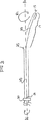
図1は熱交換カテーテル本体10を示す。カテーテル本体10は、いずれのタイプの熱交換カテーテルからなってもよい。例えば、カテーテル本体10は、流体を満たした熱交換バルーン(図6に示す)もしくは抵抗ヒーターを有する熱交換カテーテル(図1に示す)からなってもよい。本発明のカテーテル本体10からなる熱交換カテーテルシステムの好適な実施形態が、多くの米国特許において開示されている。
Throughout the embodiments, FIGS. 1-6 illustrate various configurations for moving the heat exchange surface of a catheter according to the present invention.
FIG. 1 shows a heat
本発明は、多種多様な温度を調整するカテーテルシステムを使用するために構成されていることが理解されるべきである。例えば、本発明において、使用されるカテーテルシステムは、通過する体液を暖める(例えば、電気ヒーターを備えたシステム、または熱交換流体を送り込むシステム)ために構成されたカテーテルシステムからなる。さらに、使用されるカテーテルシステムは、通過する体液を冷やす(例えば、冷却流体を循環させるシステム)ために構成されたカテーテルシステムからなる。 It should be understood that the present invention is configured to use a catheter system that regulates a wide variety of temperatures. For example, in the present invention, the catheter system used consists of a catheter system configured to warm the passing body fluid (eg, a system with an electric heater or a system that delivers a heat exchange fluid). In addition, the catheter system used consists of a catheter system configured to cool body fluid passing therethrough (eg, a system for circulating a cooling fluid).
図1に示される実施形態において、カテーテル本体10は、抵抗ヒーター13が配置された熱交換領域11からなる。この実施形態において、表面12は熱交換面からなる。
熱交換面の移動は、動作源により誘導される。
In the embodiment shown in FIG. 1, the
The movement of the heat exchange surface is guided by an operating source.
様々な実施形態において、この動作源は、少なくともカテーテル本体の一部を長手方向に貫通して延びるワイヤ、および同ワイヤを動かすために構成されたトランスデューサからなる。例えば、カテーテル本体10は、少なくともカテーテル本体の一部を長手方向に貫通して延びるワイヤ20および同ワイヤに取り付けられたトランスデューサ22を有する。
In various embodiments, the source of motion consists of a wire extending longitudinally through at least a portion of the catheter body and a transducer configured to move the wire. For example, the
動作源は熱交換領域に連結され、熱交換面への動きを伝達する。これは多くの異なる構成により実施してもよく、以下に記載した実施例に限定されるものではない。
図1において、トランスデューサ22はワイヤ20を動かすために同ワイヤに取り付けられる。トランスデューサ22は超音波トランスデューサからなることが望ましいが、そうである必要はない。
The operating source is coupled to the heat exchanging region and transmits movement to the heat exchanging surface. This may be done with many different configurations and is not limited to the examples described below.
In FIG. 1, a
好適な一実施形態において、トランスデューサ22はワイヤ20に接触して配置され、ワイヤ20の基端部21を径方向R1に前後に移動させる。
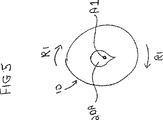
振動エネルギー(波動として)は、ワイヤ20を介して基端部21から先端部23に伝わり、カテーテル10を移動させる。ワイヤ20(およびカテーテル10)は、ほぼ径方向R1に移動し、カテーテルを平面上で「揺動させる」(即ち、図1が示されているページの面のこと、以下に記載する図6の方向R1も参照のこと)。
In a preferred embodiment, the
Vibration energy (as waves) is transmitted from the
トランスデューサ22によるカテーテル本体10の動きは、カテーテル本体の長さの少なくとも一部に沿って直接伝達される動きとなり、それにより熱交換領域11の熱交換面12を移動させる。
The movement of the
トランスデューサ22は、ワイヤ20の基端部21に連結されてもよく、ワイヤ20が「振動」もしくは「震動」し、即ち立体的に移動し(例えば、以下に記載する図6に示されるR1、R2およびR3方向)、ワイヤ20の移動は、図1に示される平面上の動きに限定されるものではない。したがって、図1に示されるシステムが、トランスデューサ22がどのようにワイヤ20の基端部21に取り付けられているかにより、2次元もしくは3次元のいずれにおいても振動するように構成されていることが理解されるべきである。
The
図6は、(カテーテル10および同カテーテルを貫通して延びる長手方向の中心軸と同一線上になるように伸ばされたワイヤ20を有する)本発明のカテーテルシステムの端面図であり、径方向の様々な向きを示す。R1方向に生じる前後移動は、1つの好適な平面における(2次元)動作を構成する。一方、R1、R2およびR3の全方向(および間に角度をなした全半径方向)において生じる動きは、3次元移動を構成する。
FIG. 6 is an end view of the catheter system of the present invention (having the
本発明において、熱交換面の「移動」はまた、少なくともカテーテル本体の一部を径方向外向き(即ちカテーテルの長手方向の中心軸に対して直交する方向)に、繰り返し偏向させることにより行われてもよい。そのような径方向の偏向は、熱交換面12からなるカテーテル本体部分を「蛇行」移動させる。これは、カテーテル本体の長手方向中心軸が同じ位置に留まるような単なる「脈」動とは区別され、例えば、流体を満たした熱交換バルーンの熱表面を径方向内向きおよび外向きに移動させ、バルーンを膨張(即ち熱交換面をカテーテル本体の中心から外向きに移動させる)および収縮(即ち熱交換面をカテーテル本体の中心から内向きに移動させる)させる。
In the present invention, “movement” of the heat exchange surface is also performed by repeatedly deflecting at least a portion of the catheter body radially outward (ie, in a direction perpendicular to the central axis in the longitudinal direction of the catheter). May be. Such radial deflection causes the catheter body portion of the
しかしながら、R1方向外向きに繰り返し偏向する少なくともカテーテル本体の一部から生じる動きは、カテーテル本体を互いに対向する2つの径方向に前後移動(カテーテル本体が好適な面において「揺動すること」)させることからなる。しかしながら、そのような動きは、少なくともカテーテル本体の一部を互いに対向する2つ以上のR1、R2およびR3方向に偏向させ、少なくともカテーテル本体10の一部を(1)「振動」もしくは「震動」させて、カテーテル本体の中心軸が時間をかけて任意の径方向に移動し、または(2)カテーテル本体10の一部がカテーテルの残りの部分を貫通して延びる長手方向の中心軸の周囲を回転する。
However, the movement resulting from at least a portion of the catheter body that repeatedly deflects outward in the R1 direction causes the catheter body to move back and forth in two radial directions facing each other (the catheter body “swings” in a preferred plane). Consists of. However, such movement causes at least a portion of the catheter body to deflect in two or more opposite R1, R2 and R3 directions and at least a portion of the catheter body 10 (1) “vibrates” or “vibrates”. The central axis of the catheter body moves in any radial direction over time, or (2) around a longitudinal central axis that extends part of the
「振動」もしくは「震動」する構成において、カテーテル本体の中心軸(図6においては、ワイヤ20と同一線上にある)は、時間をかけて中央位置に戻ることが望ましい。
図1において、熱交換面12の移動の周波数は、超音波領域内であってもよいが、そうである必要はない。超音波領域よりも低い周波数での動きもまた、本発明において意図されている。本発明の周波数の下限において、カテーテル本体は容易に目視可能な、例えば毎秒1ないし2回転でゆっくりと回転する。振幅(即ち「移動する」熱交換領域が移動するR方向における径方向の距離)は、少なくとも下限周波数においてはより大きいが、熱交換領域が配置される血管の幅により制約される。したがって、軸方向の動きも、熱交換領域上の層状の血流を遮断するために誘導されてもよい。
In a “vibrating” or “vibrating” configuration, it is desirable that the central axis of the catheter body (in FIG. 6 collinear with the wire 20) return to the central position over time.
In FIG. 1, the frequency of movement of the
この構成を変更することもまた可能である。例えば、トランスデューサ22をワイヤ20の先端部23に取り付けて、ワイヤの先端部23から基端部21へ振動しながら移動させてもよい。
It is also possible to change this configuration. For example, the
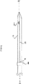
図2も熱交換カテーテル本体10を示す。カテーテル本体10は、長手方向に貫通して延びるワイヤ20およびカテーテルに取り付けられたトランスデューサ22Aを有する。この構成において、トランスデューサ22Aはワイヤ20と接触して配置され、ワイヤ20の基端部を軸方向Aに前後に移動させる。また、ワイヤ20の先端部23はカテーテルの先端部に取り付けられることが望ましい。振動エネルギーは、ワイヤ20を介してその基端部21から先端部23(代わりにワイヤ20の部分を引っ張り圧縮する部分を有する)に伝わり、カテーテル10を移動させる。この構成において、カテーテル10は、ほぼ軸方向Aに移動する。
FIG. 2 also shows the heat
図3において、動作源はまた、ワイヤを回転させるべく構成された機構を有するカテーテル本体の少なくとも一部を貫通して長手方向に延びるワイヤからなってもよい。一構成において、カテーテル本体の先端部は、以下のようにカテーテル本体10を貫通して延びる長手中心軸A1の周囲を回転する。
In FIG. 3, the operating source may also comprise a wire extending longitudinally through at least a portion of the catheter body having a mechanism configured to rotate the wire. In one configuration, the distal end of the catheter body rotates about a longitudinal central axis A1 that extends through the
熱交換カテーテル本体10が構成される。カテーテル本体10は、貫通して長手方向に延びるワイヤ20を有する。ワイヤ20は、捻れ即ち湾曲部25(明確に示すために図3において湾曲の角度が強調されている)においてわずかに湾曲する。ワイヤ20の基端部21は、回転システム30(モーターからなることが望ましい)に取り付けられる。回転システム30により、ワイヤ20は軸A1−A1の周囲を回転し、カテーテル10の先端部(およびワイヤ20の先端部23)を軸A1−A1の周囲で回転させ、先端部15を「撹拌して」移動させ、軸A1−A1からほぼ同じ径方向距離に配置される。ワイヤ20が回転すると、カテーテル10の長さ17に平行した様々な部分は、長手方向中心軸A1−A1から同距離をおいて留まる。
A heat
カテーテルが十分に伸ばされている時は、軸A1−A1は、カテーテルの長手方向中心軸と同一線上にある。図3において示されるように、カテーテルの大部分(基端部)は、軸A1−A1と同一線上に留まり、カテーテル本体の動きは、(熱交換領域を有する)先端部分における動きに限定される。 When the catheter is fully extended, axis A1-A1 is collinear with the longitudinal central axis of the catheter. As shown in FIG. 3, the majority (proximal end) of the catheter remains collinear with the axis A1-A1, and the movement of the catheter body is limited to movement at the distal end (having a heat exchange area). .
任意の様々な構成において、ワイヤ20は2つ以上の湾曲部を有する。全体的にこれらの複数の湾曲部は、カテーテル10の先端部15に形成されるので、軸A1−A1と同軸上にはならない。例えば、図7に示す他の構成において、ワイヤ20は、軸A1−A1と同軸となるカテーテル本体10の先端部15を1つにまとめて複数の湾曲部を有してもよい。この構成において、先端部15は、ワイヤ20が回転する間は軸A1−A1上に配置される。しかしながら、カテーテル本体10Aおよび10Bは、互いに対向する径方向R1に延びることが望ましい。ワイヤ20が回転する時に、カテーテル本体10Aおよび10Bの相対移動は、カテーテル10上を通過する流体を遮断しようとする。
In any of various configurations, the
他の実施形態において、ワイヤの先端部に配置された非対称の切断面(即ち径方向の突出部)により移動が生じ、ワイヤが回転する時に、カテーテルの先端部は、(カテーテルの先端部が長手方向の中心軸から同じ距離において留まり)カテーテル本体の長さの大部分を貫通して延びる長手方向の中心軸の周囲を以下に述べるように回転する。 In other embodiments, when the movement is caused by an asymmetric cutting surface (ie, a radial protrusion) disposed at the tip of the wire and the wire rotates, the tip of the catheter (the tip of the catheter is longitudinal) It stays at the same distance from the central axis of the direction) and rotates around the longitudinal central axis extending through most of the length of the catheter body as described below.
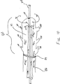
図4は、熱交換カテーテル本体10を示す。カテーテル本体10は、貫通して長手方向に延びるワイヤ20を有する。ワイヤ20は、径方向に延びる突出部27を有する。ワイヤ20の基端部21は、回転システム30(モーターからなることが望ましい)に取り付けられる。回転システム30により、ワイヤ20が軸A1−A1の周囲を回転し、突出部27もまた軸A1−A1の周囲を回転して、カテーテル本体10の先端部15(およびワイヤ20の先端部23)を軸A1−A1の周囲で回転させ、少なくともカテーテル10の先端部を移動させる。
FIG. 4 shows the heat
図5は、熱交換カテーテル本体10を示す。カテーテル本体10は、貫通して長手方向に延びるワイヤ20Aを有する。ワイヤ20は、少なくとも非対称の切断面を備えた部分を有する。ワイヤ20は、軸A1−A1の周囲を(例えば、図3および4の回転システム30と同一もしくは類似する回転システムにより)回転する。ワイヤ20は、切断面において非対称であるため、ワイヤ20Aの回転により、カテーテル本体10を移動させる。ワイヤ20Aは、その長さ全体に渡って、もしくはその長さの小部分において、非対称の切断面を任意で有してもよい。ワイヤ20Aの非対称部分が、同ワイヤの先端部23に近接して配置される場合、ワイヤ20Aの回転により、カテーテル本体10の先端部が軸A1−A1の周囲を回転し、カテーテル本体10の熱交換面12が移動する。
FIG. 5 shows the heat
図7において、熱交換領域は流体を満たしたバルーンからなり、同バルーンは、シングルルーメンバルーンもしくは複数の突出部を有するマルチルーメンバルーンであってもよい。この実施形態において、カテーテル本体は、シャフト部51および同シャフト部の先端部に取り付けられた複数の突出部を有するバルーン55からなる。熱交換領域はまた、すでに述べた実施形態のように、シャフトと一体に形成されてもよい。これらのシステムにおいて、熱交換領域の熱交換面は、熱交換バルーンの表面からなる。熱交換は、熱交換流体とバルーン間、およびバルーン表面とその上を流れる血液との間で生じる。複数の突出部を有するマルチルーメンバルーンを使用する場合は、図に示すようにバルーンの突出部が好適に包まれ、即ち中央ルーメンの周囲を撚り合わせてもよい。
In FIG. 7, the heat exchange region is composed of a balloon filled with fluid, and the balloon may be a single lumen balloon or a multi-lumen balloon having a plurality of protrusions. In this embodiment, the catheter body includes a
本発明の補足的な構成において、カテーテルは、カテーテルの熱交換領域を介して熱交換流体を循環させることにより血液と熱を交換し、熱交換領域を介して循環する流体コラムに動作を誘導することにより、動きを熱交換領域に伝達する。これは、動きを流体コラムに伝達するために、超音波移動ジェネレータをカテーテルのハブに取り付けることにより行われる。 In a complementary configuration of the present invention, the catheter exchanges heat with blood by circulating a heat exchange fluid through the heat exchange region of the catheter and directs motion to a fluid column that circulates through the heat exchange region. Thus, the movement is transmitted to the heat exchange area. This is done by attaching an ultrasonic movement generator to the catheter hub in order to transfer the motion to the fluid column.
熱交換流体の流体コラムのそのような動きは、熱交換バルーンを介して流体を脈動させる既存のシステム、即ち凝血を抑制するために必要な程度までバルーンを膨張および収縮させるシステムから区別される。一方、本発明のシステムは、外部のバルーンを単に先行技術における程度まで拡張および収縮させることなく、流体コラム内に動きを伝達できる。 Such movement of the fluid column of heat exchange fluid is distinguished from existing systems that pulsate fluid through the heat exchange balloon, i.e., systems that inflate and deflate the balloon to the extent necessary to inhibit clotting. On the other hand, the system of the present invention can transfer motion into the fluid column without simply expanding and deflating the external balloon to the extent of the prior art.
熱交換が2つの流体間において行われる場合、向流を用いることが最も効率がよい。即ち、熱交換流体の流れを、熱を交換する流体の流動方向と逆方向にするのである。熱交換カテーテルは、様々な方法で血管内に挿入され、通常の血液の流れがその時々に異なるので(即ち基端方向から先端方向、もしくは先端方向から基端方向)、本発明のカテーテルは、体液流に触れた熱交換領域部分内の流体の方向がいずれの方向にも流れるように調整され、カテーテルを血管内においていずれの方向にも挿入可能にし、熱交換流体の流動方向を調整して血管内の血流とは逆方向に流動可能にするように、任意に有効に構成される。 If heat exchange takes place between two fluids, it is most efficient to use countercurrent. That is, the flow of the heat exchange fluid is set in the direction opposite to the flow direction of the fluid exchanging heat. Since heat exchange catheters are inserted into blood vessels in various ways and normal blood flow is different from time to time (i.e., proximal to distal, or distal to proximal), the catheter of the present invention is The direction of the fluid in the heat exchange region that touched the body fluid flow is adjusted to flow in either direction, the catheter can be inserted in any direction in the blood vessel, and the flow direction of the heat exchange fluid is adjusted It is configured to be arbitrarily effective so that it can flow in the direction opposite to the blood flow in the blood vessel.
他の実施形態において、図8には、血管内の血流内に配置されるフロー偏向羽根が示されている。フロー偏向羽根は、カテーテルシャフト50上に配置してもよく、またはカテーテル52の熱交換領域上に直接配置してもよい。代わりに、ガイドワイヤ上に配置してもよく、例えば、ガイドワイヤ54の先端部上でもよく、即ち少なくともカテーテル本体の一部を介して血流内を通過する。フロー偏向羽根は、血流内のどこに配置されても、血流内を移動して動きを熱交換領域に伝達する。
In another embodiment, FIG. 8 shows a flow deflection vane that is placed in the blood flow in a blood vessel . The flow deflection vanes may be located on the
図は3箇所全てにおいてフロー偏向羽根を示すが、当業者にとっては、一構成において、単一のフロー偏向羽根もしくは複数のフロー偏向羽根、あるいはいずれの組み合わせも使用できること、およびカテーテルシステムが本発明の範囲内にあることが理解されよう。同様に、フロー偏向羽根は、カテーテルの一部もしくはガイドワイヤから突出した固定した構造であってもよく、または血流内に配置された場合に動きを誘導すべく設計された熱交換領域、シャフトもしくはガイドワイヤから構成されてもよい。例えば、複数の突出部を有する熱交換バルーンが、動きを誘導する非対称の突出部を有する場合、これは本発明が意図する範囲である。同様に、ガイドワイヤが図において使用されているが、カテーテルから延びる温度探知棒などの類似するワイヤ構造が動きを誘導するように構成されてもよく、これもまた本発明の意図する範囲である。 Although the figure shows the flow deflection vanes in all three locations, for those skilled in the art, a single flow deflection vane or multiple flow deflection vanes, or any combination, can be used in one configuration, and a catheter system of the present invention. It will be understood that it is within range. Similarly, the flow deflection vane may be a fixed structure protruding from a portion of the catheter or guidewire, or a heat exchange region, shaft designed to induce movement when placed in the bloodstream Or you may comprise from a guide wire. For example, if a heat exchange balloon having a plurality of protrusions has an asymmetric protrusion that induces movement, this is within the scope of the present invention. Similarly, although a guide wire is used in the figure, a similar wire structure, such as a temperature sensing rod extending from the catheter, may be configured to induce movement, which is also within the intended scope of the present invention. .
動きを熱交換面に伝達する他のシステムは、プルワイヤおよびワイヤを引っ張って放すためのプルワイヤ上の可変張力源からなる。そのようなシステムは、図9Aおよび9Bに示される。熱交換面70を有するカテーテルは、同カテーテルを貫通して、熱交換領域付近の取り付け位置74まで延びるプルワイヤ72を有する。張力源、例えば逆動作源76はプルワイヤに取り付けられる。取り付け位置は非対称であり、例えば円形ルーメンの一面上にあり、ワイヤが引っ張られた時に、熱交換面は径方向に湾曲し、ワイヤが押圧もしくは開放された時に、熱交換面はカテーテル軸に沿って相対的に直線状となる。プルワイヤを繰り返し引っ張ってから放すことにより、熱交換面は血流内を移動して熱交換を向上させる。
Another system for transferring motion to the heat exchange surface consists of a pull wire and a variable tension source on the pull wire to pull and release the wire. Such a system is shown in FIGS. 9A and 9B. A catheter having a
熱交換面の回転移動もまた、その表面は流体を撹拌する要素を有するが、熱交換を向上させる。例えば、図10において、カテーテルは、流入ルーメン80および同軸熱交換領域82を有する。流体密封ベアリング84は、基端カテーテル本体86と熱交換領域との間に配置される。熱交換領域の表面は、フロー偏向羽根などの一連の突出部を形成する。この構成において、表面上の血流は熱交換領域の矢印90により示される回転移動を伝え、カテーテルシャフト86に対して回転する。ベアリング84は、矢印92で示される熱交換流体が、流入ルーメン80を熱交換領域94の内部ルーメン内に流し、流出ルーメン96に戻すように、流体密閉シールが維持される間に回転する。作業ルーメン98もまた、カテーテル内にあり、同作業ルーメンは流入ルーメン80の中心に配置される。作業ルーメンは熱交換領域の先端方向に延ばしてもよい。その場合、ベアリングは、作業ルーメンが熱交換領域100にある場合に構成される。代わりに、その場所を取り付け位置としてもよく、作業ルーメンの回転により熱交換領域が回転する。作業ルーメンの基端部に取り付けられた回転動作源は、例えば、患者の外部において、回転運動を熱交換面に伝達するように構成してもよい。
The rotational movement of the heat exchange surface also improves the heat exchange, although the surface has elements that stir the fluid. For example, in FIG. 10, the catheter has an inflow lumen 80 and a coaxial heat exchange region 82. A fluid tight bearing 84 is disposed between the proximal catheter body 86 and the heat exchange area. The surface of the heat exchange area forms a series of protrusions such as flow deflection vanes. In this configuration, the blood flow on the surface transmits the rotational movement indicated by arrows 90 in the heat exchange region and rotates relative to the catheter shaft 86. The bearing 84 rotates while the fluid tight seal is maintained so that the heat exchange fluid, indicated by
本願において記載した実施形態は、本発明によるシステムを説明するためのものである。本発明は、そのような実施形態に限定されるものではない。むしろ、本発明は、添付の特許請求の範囲に記載された全ての構成、および当業者にとっては明白であろうそれらの変更も含まれることが理解されるべきである。 The embodiments described in this application are intended to illustrate a system according to the present invention. The present invention is not limited to such an embodiment. Rather, it is to be understood that the invention includes all arrangements set forth in the appended claims and modifications that would be apparent to those skilled in the art.
Claims (13)
血液と接触する熱交換面を有する熱交換領域を備えたカテーテル本体と、
前記熱交換面を介して熱交換を行うことにより血液が冷却されるように前記熱交換領域を冷却するための装置と、
血液を冷却すべく前記熱交換面と血液との間で熱交換が行われている間に、動作を同熱交換面に伝達する動作源とを備え、
前記動作源は、前記カテーテル本体の一部を長手方向に貫通して延びるワイヤと、同ワイヤに接続され、同ワイヤを振動させて径方向または軸線方向に移動させて、その動作を前記カテーテル本体に伝達して、同カテーテル本体の熱交換面を移動させるとともに血液を攪拌させるように構成されたトランスデューサとからなるシステム。A catheter system for adjusting a patient's internal temperature by changing the temperature of the blood flow in the patient's blood vessel,
A catheter body with a heat exchange region having a heat exchange surface in contact with blood;
An apparatus for cooling the heat exchange region such that blood is cooled by performing heat exchange through the heat exchange surface;
While the heat exchange between the heat exchange surface and the blood to cool the blood is being performed, and a behavior source you transmit operation in the heat exchange surface,
The motion source includes a wire extending in a longitudinal direction through a part of the catheter body, and connected to the wire, and the wire is vibrated and moved in a radial direction or an axial direction to move the catheter body. And a transducer configured to move the heat exchange surface of the catheter body and stir the blood .
Applications Claiming Priority (2)
| Application Number | Priority Date | Filing Date | Title |
|---|---|---|---|
| US09/872,818 US6752786B2 (en) | 2001-05-31 | 2001-05-31 | Moving heat exchange catheter system |
| PCT/US2002/017139 WO2002096329A1 (en) | 2001-05-31 | 2002-05-31 | Moving heat exchange catheter system |
Publications (2)
| Publication Number | Publication Date |
|---|---|
| JP2004527346A JP2004527346A (en) | 2004-09-09 |
| JP4355498B2 true JP4355498B2 (en) | 2009-11-04 |
Family
ID=25360359
Family Applications (1)
| Application Number | Title | Priority Date | Filing Date |
|---|---|---|---|
| JP2002592846A Expired - Fee Related JP4355498B2 (en) | 2001-05-31 | 2002-05-31 | Movable heat exchange catheter system |
Country Status (9)
| Country | Link |
|---|---|
| US (4) | US6752786B2 (en) |
| EP (1) | EP1389988B1 (en) |
| JP (1) | JP4355498B2 (en) |
| AT (1) | ATE336211T1 (en) |
| AU (1) | AU2002310229B2 (en) |
| CA (1) | CA2448206C (en) |
| DE (1) | DE60213970T2 (en) |
| ES (1) | ES2271268T3 (en) |
| WO (1) | WO2002096329A1 (en) |
Families Citing this family (90)
| Publication number | Priority date | Publication date | Assignee | Title |
|---|---|---|---|---|
| US6974463B2 (en) | 1999-02-09 | 2005-12-13 | Innercool Therapies, Inc. | System and method for patient temperature control employing temperature projection algorithm |
| US8128595B2 (en) * | 1998-04-21 | 2012-03-06 | Zoll Circulation, Inc. | Method for a central venous line catheter having a temperature control system |
| US6338727B1 (en) | 1998-08-13 | 2002-01-15 | Alsius Corporation | Indwelling heat exchange catheter and method of using same |
| US7914564B2 (en) | 1999-02-09 | 2011-03-29 | Innercool Therapies, Inc. | System and method for patient temperature control employing temperature projection algorithm |
| US6811551B2 (en) * | 1999-12-14 | 2004-11-02 | Radiant Medical, Inc. | Method for reducing myocardial infarct by application of intravascular hypothermia |
| US8123789B2 (en) | 2002-04-29 | 2012-02-28 | Rohit Khanna | Central nervous system cooling catheter |
| US6878147B2 (en) * | 2001-11-02 | 2005-04-12 | Vivant Medical, Inc. | High-strength microwave antenna assemblies |
| US7128739B2 (en) | 2001-11-02 | 2006-10-31 | Vivant Medical, Inc. | High-strength microwave antenna assemblies and methods of use |
| US7617005B2 (en) * | 2002-04-08 | 2009-11-10 | Ardian, Inc. | Methods and apparatus for thermally-induced renal neuromodulation |
| US7744583B2 (en) * | 2003-02-03 | 2010-06-29 | Boston Scientific Scimed | Systems and methods of de-endothelialization |
| US20040199114A1 (en) * | 2003-04-01 | 2004-10-07 | Alsius Corporation | Intravascular heat exchange catheter with tissue preservative |
| US7311703B2 (en) | 2003-07-18 | 2007-12-25 | Vivant Medical, Inc. | Devices and methods for cooling microwave antennas |
| US8672988B2 (en) * | 2004-10-22 | 2014-03-18 | Medtronic Cryocath Lp | Method and device for local cooling within an organ using an intravascular device |
| US20060190066A1 (en) * | 2005-02-23 | 2006-08-24 | Worthen William J | System and method for bringing hypothermia rapidly onboard |
| US20060190062A1 (en) * | 2005-02-23 | 2006-08-24 | Worthen William J | System and method for reducing shivering when using external cooling pads |
| US7425216B2 (en) * | 2005-03-01 | 2008-09-16 | Alsius Corporation | System and method for treating cardiac arrest and myocardial infarction |
| US7892269B2 (en) | 2005-04-18 | 2011-02-22 | Zoll Circulation, Inc. | External heat exchange pad for patient |
| EP2929862B1 (en) | 2005-04-27 | 2017-02-08 | Zoll Circulation, Inc. | System for providing enhanced heat transfer from a body |
| US7740627B2 (en) * | 2005-04-29 | 2010-06-22 | Medtronic Cryocath Lp | Surgical method and apparatus for treating atrial fibrillation |
| US7794455B2 (en) * | 2005-04-29 | 2010-09-14 | Medtronic Cryocath Lp | Wide area ablation of myocardial tissue |
| US7799019B2 (en) | 2005-05-10 | 2010-09-21 | Vivant Medical, Inc. | Reinforced high strength microwave antenna |
| US7905830B2 (en) * | 2005-05-13 | 2011-03-15 | Ethicon Endo-Surgery, Inc. | Sheath for use with an endoscope |
| AU2006263448B2 (en) * | 2005-06-29 | 2013-01-24 | Radiant Medical, Inc. | Devices, systems and methods for rapid endovascular cooling |
| US7951182B2 (en) | 2005-07-14 | 2011-05-31 | Zoll Circulation, Inc. | System and method for leak detection in external cooling pad |
| US20070167826A1 (en) * | 2005-11-30 | 2007-07-19 | Warren Lee | Apparatuses for thermal management of actuated probes, such as catheter distal ends |
| US9937332B2 (en) * | 2006-02-06 | 2018-04-10 | Medtronic Cryocath Lp | Cryo-perfusion balloon device |
| US7822485B2 (en) | 2006-09-25 | 2010-10-26 | Zoll Circulation, Inc. | Method and apparatus for spinal cooling |
| US7867266B2 (en) | 2006-11-13 | 2011-01-11 | Zoll Circulation, Inc. | Temperature management system with assist mode for use with heart-lung machine |
| US7892270B2 (en) | 2006-11-21 | 2011-02-22 | Zoll Circulation Inc. | Temperature management system and method for burn patients |
| US8296191B1 (en) | 2007-01-10 | 2012-10-23 | Stte, Llc | Electronic open-market commerce system and method |
| US8353893B2 (en) | 2007-03-07 | 2013-01-15 | Zoll Circulation, Inc. | System and method for rapidly cooling cardiac arrest patient |
| CA2684807A1 (en) | 2007-04-05 | 2008-10-16 | Velomedix, Inc. | Automated therapy system and method |
| WO2008124643A1 (en) * | 2007-04-05 | 2008-10-16 | Velomedix, Inc. | Device and method for safe access to a body cavity |
| US7998139B2 (en) * | 2007-04-25 | 2011-08-16 | Vivant Medical, Inc. | Cooled helical antenna for microwave ablation |
| US9737692B2 (en) | 2007-05-18 | 2017-08-22 | Zoll Circulation, Inc. | System and method for effecting non-standard fluid line connections |
| US8353901B2 (en) | 2007-05-22 | 2013-01-15 | Vivant Medical, Inc. | Energy delivery conduits for use with electrosurgical devices |
| US9023024B2 (en) | 2007-06-20 | 2015-05-05 | Covidien Lp | Reflective power monitoring for microwave applications |
| WO2009009540A1 (en) | 2007-07-09 | 2009-01-15 | Velomedix, Inc. | Hypothermia devices and methods |
| WO2009076560A2 (en) * | 2007-12-12 | 2009-06-18 | The Board Of Trustees Of The Leland Stanford Junior University | Method and apparatus for magnetic separation of cells |
| US8608696B1 (en) | 2009-02-24 | 2013-12-17 | North Carolina State University | Rapid fluid cooling devices and methods for cooling fluids |
| US9326890B2 (en) | 2009-02-26 | 2016-05-03 | Advanced Cooling Therapy, Inc. | Devices and methods for controlling patient temperature |
| ES2575302T3 (en) * | 2009-02-26 | 2016-06-27 | Advanced Cooling Therapy, Inc. | Devices for controlling patient temperature |
| US9301871B2 (en) | 2009-02-26 | 2016-04-05 | Advanced Cooling Therapy, Inc. | Devices and methods for controlling patient temperature |
| US9622909B2 (en) | 2009-02-26 | 2017-04-18 | Advanced Cooling Therapy, Inc. | Devices and methods for controlling patient temperature |
| US8926602B2 (en) | 2010-01-28 | 2015-01-06 | Medtronic Cryocath Lp | Triple balloon catheter |
| US9622670B2 (en) | 2010-07-09 | 2017-04-18 | Potrero Medical, Inc. | Method and apparatus for pressure measurement |
| KR102291972B1 (en) | 2011-01-19 | 2021-08-23 | 프랙틸 헬쓰, 인코포레이티드 | Devices and methods for the treatment of tissue |
| US20140058277A1 (en) * | 2011-03-09 | 2014-02-27 | Nanyang Polytechnic | Blood flow rate measurement system |
| CN103781443B (en) | 2011-04-13 | 2016-07-06 | 低温疗法有限公司 | Use the plaques stabilize of low temperature energy |
| US9387031B2 (en) | 2011-07-29 | 2016-07-12 | Medtronic Ablation Frontiers Llc | Mesh-overlayed ablation and mapping device |
| US9283110B2 (en) | 2011-09-20 | 2016-03-15 | Zoll Circulation, Inc. | Patient temperature control catheter with outer sleeve cooled by inner sleeve |
| US8974478B2 (en) | 2011-09-20 | 2015-03-10 | Covidien Lp | Ultrasonic surgical system having a fluid cooled blade and related cooling methods therefor |
| US9314370B2 (en) | 2011-09-28 | 2016-04-19 | Zoll Circulation, Inc. | Self-centering patient temperature control catheter |
| US9259348B2 (en) | 2011-09-28 | 2016-02-16 | Zoll Circulation, Inc. | Transatrial patient temperature control catheter |
| US8888832B2 (en) | 2011-09-28 | 2014-11-18 | Zoll Circulation, Inc. | System and method for doubled use of patient temperature control catheter |
| US10045881B2 (en) | 2011-09-28 | 2018-08-14 | Zoll Circulation, Inc. | Patient temperature control catheter with helical heat exchange paths |
| DE102012101525B4 (en) * | 2012-02-24 | 2013-12-12 | Acandis Gmbh & Co. Kg | Medical device for endovascular tempering of blood and arrangement with such a device |
| EP4066764A1 (en) * | 2012-02-27 | 2022-10-05 | Fractyl Health, Inc. | Heat ablation systems and devices for the treatment of tissue |
| AU2013249043B2 (en) | 2012-04-19 | 2017-04-27 | Fractyl Health, Inc. | Tissue expansion devices, system and methods |
| DE102012104381A1 (en) * | 2012-05-22 | 2013-11-28 | Acandis Gmbh & Co. Kg | Medical system for the endovascular tempering of blood and medical catheters |
| EP2879605A4 (en) | 2012-07-30 | 2016-04-06 | Fractyl Lab Inc | Electrical energy ablation systems, devices and methods for the treatment of tissue |
| EP2882362B1 (en) | 2012-08-09 | 2024-01-03 | Fractyl Health, Inc. | Ablation systems, devices and methods for the treatment of tissue |
| US9113911B2 (en) | 2012-09-06 | 2015-08-25 | Medtronic Ablation Frontiers Llc | Ablation device and method for electroporating tissue cells |
| US9801756B2 (en) | 2012-09-28 | 2017-10-31 | Zoll Circulation, Inc. | Intravascular heat exchange catheter and system with RFID coupling |
| US9433528B2 (en) | 2012-09-28 | 2016-09-06 | Zoll Circulation, Inc. | Intravascular heat exchange catheter with rib cage-like coolant path |
| US9717625B2 (en) | 2012-09-28 | 2017-08-01 | Zoll Circulation, Inc. | Intravascular heat exchange catheter with non-round coiled coolant path |
| US9241827B2 (en) | 2012-09-28 | 2016-01-26 | Zoll Circulation, Inc. | Intravascular heat exchange catheter with multiple spaced apart discrete coolant loops |
| EP2903626A4 (en) | 2012-10-05 | 2016-10-19 | Fractyl Lab Inc | Methods, systems and devices for performing multiple treatments on a patient |
| WO2014197632A2 (en) | 2013-06-04 | 2014-12-11 | Fractyl Laboratories, Inc. | Methods, systems and devices for reducing the luminal surface area of the gastrointestinal tract |
| US20160354144A1 (en) * | 2013-09-12 | 2016-12-08 | Fractyl Laboratories, Inc. | Systems, methods and devices for treatment of target tissue |
| JP6603660B2 (en) | 2013-11-22 | 2019-11-06 | フラクティル ラボラトリーズ インコーポレイテッド | System, device and method for generating treatment constraints in the gastrointestinal tract |
| US9474644B2 (en) | 2014-02-07 | 2016-10-25 | Zoll Circulation, Inc. | Heat exchange system for patient temperature control with multiple coolant chambers for multiple heat exchange modalities |
| US10792185B2 (en) | 2014-02-14 | 2020-10-06 | Zoll Circulation, Inc. | Fluid cassette with polymeric membranes and integral inlet and outlet tubes for patient heat exchange system |
| US10500088B2 (en) | 2014-02-14 | 2019-12-10 | Zoll Circulation, Inc. | Patient heat exchange system with two and only two fluid loops |
| US11033424B2 (en) | 2014-02-14 | 2021-06-15 | Zoll Circulation, Inc. | Fluid cassette with tensioned polymeric membranes for patient heat exchange system |
| JP2017513546A (en) | 2014-03-07 | 2017-06-01 | ゾール サーキュレイション インコーポレイテッドZOLL Circulation,Inc. | Intravascular heat exchange system and method using blood flow monitoring and notification function |
| US10959774B2 (en) | 2014-03-24 | 2021-03-30 | Fractyl Laboratories, Inc. | Injectate delivery devices, systems and methods |
| US11185367B2 (en) | 2014-07-16 | 2021-11-30 | Fractyl Health, Inc. | Methods and systems for treating diabetes and related diseases and disorders |
| US9844641B2 (en) | 2014-07-16 | 2017-12-19 | Fractyl Laboratories, Inc. | Systems, devices and methods for performing medical procedures in the intestine |
| WO2016011269A1 (en) | 2014-07-16 | 2016-01-21 | Fractyl Laboratories, Inc. | Methods and systems for treating diabetes and related diseases and disorders |
| US9784263B2 (en) | 2014-11-06 | 2017-10-10 | Zoll Circulation, Inc. | Heat exchange system for patient temperature control with easy loading high performance peristaltic pump |
| US11359620B2 (en) | 2015-04-01 | 2022-06-14 | Zoll Circulation, Inc. | Heat exchange system for patient temperature control with easy loading high performance peristaltic pump |
| US11213423B2 (en) | 2015-03-31 | 2022-01-04 | Zoll Circulation, Inc. | Proximal mounting of temperature sensor in intravascular temperature management catheter |
| US10537465B2 (en) | 2015-03-31 | 2020-01-21 | Zoll Circulation, Inc. | Cold plate design in heat exchanger for intravascular temperature management catheter and/or heat exchange pad |
| US10022265B2 (en) | 2015-04-01 | 2018-07-17 | Zoll Circulation, Inc. | Working fluid cassette with hinged plenum or enclosure for interfacing heat exchanger with intravascular temperature management catheter |
| WO2017019730A1 (en) | 2015-07-27 | 2017-02-02 | University Of Maryland, Baltimore | Body temperature management devices and methods |
| CN106618728B (en) * | 2016-12-26 | 2019-08-27 | 迈德医疗科技(上海)有限公司 | Ablation apparatus |
| US11185440B2 (en) | 2017-02-02 | 2021-11-30 | Zoll Circulation, Inc. | Devices, systems and methods for endovascular temperature control |
| US11337851B2 (en) | 2017-02-02 | 2022-05-24 | Zoll Circulation, Inc. | Devices, systems and methods for endovascular temperature control |
| US11116657B2 (en) | 2017-02-02 | 2021-09-14 | Zoll Circulation, Inc. | Devices, systems and methods for endovascular temperature control |
Family Cites Families (58)
| Publication number | Priority date | Publication date | Assignee | Title |
|---|---|---|---|---|
| US5791A (en) * | 1848-09-19 | Lock and escutcheon | ||
| US2308484A (en) * | 1939-01-16 | 1943-01-19 | Davol Rubber Co | Catheter |
| US3425419A (en) * | 1964-08-08 | 1969-02-04 | Angelo Actis Dato | Method of lowering and raising the temperature of the human body |
| US5019075A (en) * | 1984-10-24 | 1991-05-28 | The Beth Israel Hospital | Method and apparatus for angioplasty |
| US4754752A (en) * | 1986-07-28 | 1988-07-05 | Robert Ginsburg | Vascular catheter |
| US4762130A (en) * | 1987-01-15 | 1988-08-09 | Thomas J. Fogarty | Catheter with corkscrew-like balloon |
| US5041089A (en) * | 1987-12-11 | 1991-08-20 | Devices For Vascular Intervention, Inc. | Vascular dilation catheter construction |
| US4941475A (en) * | 1988-08-30 | 1990-07-17 | Spectramed, Inc. | Thermodilution by heat exchange |
| US5191883A (en) * | 1988-10-28 | 1993-03-09 | Prutech Research And Development Partnership Ii | Device for heating tissue in a patient's body |
| NL8902559A (en) * | 1989-10-16 | 1991-05-16 | Du Med Bv | INTRA-LUMINAL DEVICE. |
| US5624392A (en) * | 1990-05-11 | 1997-04-29 | Saab; Mark A. | Heat transfer catheters and methods of making and using same |
| US5304115A (en) * | 1991-01-11 | 1994-04-19 | Baxter International Inc. | Ultrasonic angioplasty device incorporating improved transmission member and ablation probe |
| US5250070A (en) * | 1991-05-28 | 1993-10-05 | Parodi Juan C | Less traumatic angioplasty balloon for arterial dilatation |
| US5304214A (en) * | 1992-01-21 | 1994-04-19 | Med Institute, Inc. | Transurethral ablation catheter |
| US5269758A (en) | 1992-04-29 | 1993-12-14 | Taheri Syde A | Intravascular catheter and method for treatment of hypothermia |
| US6110168A (en) * | 1993-02-10 | 2000-08-29 | Radiant Medical, Inc. | Method and apparatus for controlling a patient's body temperature by in situ blood temperature modifications |
| US5837003A (en) * | 1993-02-10 | 1998-11-17 | Radiant Medical, Inc. | Method and apparatus for controlling a patient's body temperature by in situ blood temperature modification |
| US5486208A (en) * | 1993-02-10 | 1996-01-23 | Ginsburg; Robert | Method and apparatus for controlling a patient's body temperature by in situ blood temperature modification |
| GB2283678B (en) * | 1993-11-09 | 1998-06-03 | Spembly Medical Ltd | Cryosurgical catheter probe |
| US6245068B1 (en) * | 1994-08-08 | 2001-06-12 | Scimed Life Systems, Inc. | Resilient radiopaque electrophysiology electrodes and probes including the same |
| US5879329A (en) * | 1997-01-22 | 1999-03-09 | Radiant Medical, Inc. | Infusion systems and methods for introducing fluids into the body within a desired temperature range |
| US5972026A (en) * | 1997-04-07 | 1999-10-26 | Broncus Technologies, Inc. | Bronchial stenter having diametrically adjustable electrodes |
| US6200333B1 (en) * | 1997-04-07 | 2001-03-13 | Broncus Technologies, Inc. | Bronchial stenter |
| US6254626B1 (en) * | 1998-03-24 | 2001-07-03 | Innercool Therapies, Inc. | Articulation device for selective organ cooling apparatus |
| US6231595B1 (en) * | 1998-03-31 | 2001-05-15 | Innercool Therapies, Inc. | Circulating fluid hypothermia method and apparatus |
| US6261312B1 (en) * | 1998-06-23 | 2001-07-17 | Innercool Therapies, Inc. | Inflatable catheter for selective organ heating and cooling and method of using the same |
| US6245095B1 (en) * | 1998-03-24 | 2001-06-12 | Innercool Therapies, Inc. | Method and apparatus for location and temperature specific drug action such as thrombolysis |
| US6238428B1 (en) * | 1998-01-23 | 2001-05-29 | Innercool Therapies, Inc. | Selective organ cooling apparatus and method employing turbulence-inducing element with curved terminations |
| US6312452B1 (en) * | 1998-01-23 | 2001-11-06 | Innercool Therapies, Inc. | Selective organ cooling catheter with guidewire apparatus and temperature-monitoring device |
| US6251130B1 (en) * | 1998-03-24 | 2001-06-26 | Innercool Therapies, Inc. | Device for applications of selective organ cooling |
| US6051019A (en) * | 1998-01-23 | 2000-04-18 | Del Mar Medical Technologies, Inc. | Selective organ hypothermia method and apparatus |
| US6325818B1 (en) * | 1999-10-07 | 2001-12-04 | Innercool Therapies, Inc. | Inflatable cooling apparatus for selective organ hypothermia |
| US6096068A (en) | 1998-01-23 | 2000-08-01 | Innercool Therapies, Inc. | Selective organ cooling catheter and method of using the same |
| US6251129B1 (en) * | 1998-03-24 | 2001-06-26 | Innercool Therapies, Inc. | Method for low temperature thrombolysis and low temperature thrombolytic agent with selective organ temperature control |
| US6042559A (en) * | 1998-02-24 | 2000-03-28 | Innercool Therapies, Inc. | Insulated catheter for selective organ perfusion |
| US6224624B1 (en) * | 1998-03-24 | 2001-05-01 | Innercool Therapies, Inc. | Selective organ cooling apparatus and method |
| US6645234B2 (en) * | 1998-04-21 | 2003-11-11 | Alsius Corporation | Cardiovascular guiding catheter with heat exchange properties and methods of use |
| US6338727B1 (en) | 1998-08-13 | 2002-01-15 | Alsius Corporation | Indwelling heat exchange catheter and method of using same |
| US6126684A (en) * | 1998-04-21 | 2000-10-03 | The Regents Of The University Of California | Indwelling heat exchange catheter and method of using same |
| US6149670A (en) * | 1999-03-11 | 2000-11-21 | Alsius Corporation | Method and system for treating cardiac arrest using hypothermia |
| US6419643B1 (en) * | 1998-04-21 | 2002-07-16 | Alsius Corporation | Central venous catheter with heat exchange properties |
| US6241722B1 (en) * | 1998-06-17 | 2001-06-05 | Cryogen, Inc. | Cryogenic device, system and method of using same |
| US6450990B1 (en) | 1998-08-13 | 2002-09-17 | Alsius Corporation | Catheter with multiple heating/cooling fibers employing fiber spreading features |
| AU761785B2 (en) | 1998-09-25 | 2003-06-12 | Alcon Laboratories, Inc. | Sustained release, and comfortable ophthalmic composition and method for ocular therapy |
| US6146411A (en) * | 1998-12-24 | 2000-11-14 | Alsius Corporation | Cooling system for indwelling heat exchange catheter |
| US6299599B1 (en) * | 1999-02-19 | 2001-10-09 | Alsius Corporation | Dual balloon central venous line catheter temperature control system |
| US6019703A (en) * | 1999-03-23 | 2000-02-01 | Daimlerchrysler Corporation | Transmission assembly for vehicle with torque converter clutch and method for engaging this clutch |
| US6290717B1 (en) * | 1999-03-31 | 2001-09-18 | Alsius Corporation | Temperature probe and interconnect cable for hypothermia catheter temperature feedback |
| US6358273B1 (en) * | 1999-04-09 | 2002-03-19 | Oratec Inventions, Inc. | Soft tissue heating apparatus with independent, cooperative heating sources |
| US6165207A (en) * | 1999-05-27 | 2000-12-26 | Alsius Corporation | Method of selectively shaping hollow fibers of heat exchange catheter |
| US6287326B1 (en) * | 1999-08-02 | 2001-09-11 | Alsius Corporation | Catheter with coiled multi-lumen heat transfer extension |
| US6231594B1 (en) * | 1999-08-11 | 2001-05-15 | Radiant Medical, Inc. | Method of controlling body temperature while reducing shivering |
| US6264679B1 (en) * | 1999-08-20 | 2001-07-24 | Radiant Medical, Inc. | Heat exchange catheter with discrete heat exchange elements |
| US6811551B2 (en) * | 1999-12-14 | 2004-11-02 | Radiant Medical, Inc. | Method for reducing myocardial infarct by application of intravascular hypothermia |
| WO2002047577A2 (en) * | 2000-12-15 | 2002-06-20 | Alsius Corporation | Radio frequency patient heating system |
| US6451045B1 (en) * | 2001-02-22 | 2002-09-17 | Alsius Corporation | Heat exchange catheter having a helically wrapped heat exchanger |
| US6666858B2 (en) * | 2001-04-12 | 2003-12-23 | Scimed Life Systems, Inc. | Cryo balloon for atrial ablation |
| US6887263B2 (en) * | 2002-10-18 | 2005-05-03 | Radiant Medical, Inc. | Valved connector assembly and sterility barriers for heat exchange catheters and other closed loop catheters |
-
2001
- 2001-05-31 US US09/872,818 patent/US6752786B2/en not_active Expired - Lifetime
-
2002
- 2002-05-08 US US10/142,659 patent/US20020183692A1/en not_active Abandoned
- 2002-05-31 ES ES02737291T patent/ES2271268T3/en not_active Expired - Lifetime
- 2002-05-31 AU AU2002310229A patent/AU2002310229B2/en not_active Ceased
- 2002-05-31 AT AT02737291T patent/ATE336211T1/en not_active IP Right Cessation
- 2002-05-31 JP JP2002592846A patent/JP4355498B2/en not_active Expired - Fee Related
- 2002-05-31 EP EP02737291A patent/EP1389988B1/en not_active Expired - Lifetime
- 2002-05-31 DE DE60213970T patent/DE60213970T2/en not_active Expired - Lifetime
- 2002-05-31 CA CA2448206A patent/CA2448206C/en not_active Expired - Fee Related
- 2002-05-31 WO PCT/US2002/017139 patent/WO2002096329A1/en active Search and Examination
-
2003
- 2003-12-17 US US10/738,066 patent/US20040133256A1/en not_active Abandoned
-
2004
- 2004-05-26 US US10/855,434 patent/US7238166B2/en not_active Expired - Fee Related
Also Published As
| Publication number | Publication date |
|---|---|
| US20020183691A1 (en) | 2002-12-05 |
| WO2002096329A1 (en) | 2002-12-05 |
| US20020183692A1 (en) | 2002-12-05 |
| DE60213970T2 (en) | 2007-04-26 |
| ES2271268T3 (en) | 2007-04-16 |
| US7238166B2 (en) | 2007-07-03 |
| US20040133256A1 (en) | 2004-07-08 |
| AU2002310229B2 (en) | 2007-12-06 |
| CA2448206A1 (en) | 2002-12-05 |
| ATE336211T1 (en) | 2006-09-15 |
| EP1389988B1 (en) | 2006-08-16 |
| CA2448206C (en) | 2011-07-12 |
| US20040225342A1 (en) | 2004-11-11 |
| EP1389988A1 (en) | 2004-02-25 |
| EP1389988A4 (en) | 2005-03-23 |
| DE60213970D1 (en) | 2006-09-28 |
| US6752786B2 (en) | 2004-06-22 |
| JP2004527346A (en) | 2004-09-09 |
Similar Documents
| Publication | Publication Date | Title |
|---|---|---|
| JP4355498B2 (en) | Movable heat exchange catheter system | |
| AU2002310229A1 (en) | Moving heat exchange catheter system | |
| US6224624B1 (en) | Selective organ cooling apparatus and method | |
| JP4610825B2 (en) | Heat exchange catheter with a separate heat exchange element | |
| US6551349B2 (en) | Selective organ cooling apparatus | |
| US6261312B1 (en) | Inflatable catheter for selective organ heating and cooling and method of using the same | |
| JP3676234B2 (en) | Method and apparatus for selective organ cooling | |
| US6692488B2 (en) | Apparatus for cell necrosis | |
| US7018399B2 (en) | Method of making selective organ cooling catheter | |
| US20120203201A1 (en) | Methods for Preparing a Heat Exchange Catheter System and for Heating and/or Cooling a Subject's Body | |
| JP2010137067A (en) | Multiple lumen heat exchange catheter | |
| AU2007242941A1 (en) | Methods and apparatus for regional and whole body temperature modification |
Legal Events
| Date | Code | Title | Description |
|---|---|---|---|
| A621 | Written request for application examination |
Free format text: JAPANESE INTERMEDIATE CODE: A621 Effective date: 20050524 |
|
| A131 | Notification of reasons for refusal |
Free format text: JAPANESE INTERMEDIATE CODE: A131 Effective date: 20080401 |
|
| A601 | Written request for extension of time |
Free format text: JAPANESE INTERMEDIATE CODE: A601 Effective date: 20080701 |
|
| A602 | Written permission of extension of time |
Free format text: JAPANESE INTERMEDIATE CODE: A602 Effective date: 20080708 |
|
| A521 | Request for written amendment filed |
Free format text: JAPANESE INTERMEDIATE CODE: A523 Effective date: 20080930 |
|
| TRDD | Decision of grant or rejection written | ||
| A01 | Written decision to grant a patent or to grant a registration (utility model) |
Free format text: JAPANESE INTERMEDIATE CODE: A01 Effective date: 20090707 |
|
| A01 | Written decision to grant a patent or to grant a registration (utility model) |
Free format text: JAPANESE INTERMEDIATE CODE: A01 |
|
| A61 | First payment of annual fees (during grant procedure) |
Free format text: JAPANESE INTERMEDIATE CODE: A61 Effective date: 20090803 |
|
| R150 | Certificate of patent or registration of utility model |
Free format text: JAPANESE INTERMEDIATE CODE: R150 |
|
| FPAY | Renewal fee payment (event date is renewal date of database) |
Free format text: PAYMENT UNTIL: 20120807 Year of fee payment: 3 |
|
| FPAY | Renewal fee payment (event date is renewal date of database) |
Free format text: PAYMENT UNTIL: 20130807 Year of fee payment: 4 |
|
| R250 | Receipt of annual fees |
Free format text: JAPANESE INTERMEDIATE CODE: R250 |
|
| R250 | Receipt of annual fees |
Free format text: JAPANESE INTERMEDIATE CODE: R250 |
|
| R250 | Receipt of annual fees |
Free format text: JAPANESE INTERMEDIATE CODE: R250 |
|
| R250 | Receipt of annual fees |
Free format text: JAPANESE INTERMEDIATE CODE: R250 |
|
| R250 | Receipt of annual fees |
Free format text: JAPANESE INTERMEDIATE CODE: R250 |
|
| LAPS | Cancellation because of no payment of annual fees |