JP4355019B1 - Pipe fitting - Google Patents
Pipe fitting Download PDFInfo
- Publication number
- JP4355019B1 JP4355019B1 JP2008273536A JP2008273536A JP4355019B1 JP 4355019 B1 JP4355019 B1 JP 4355019B1 JP 2008273536 A JP2008273536 A JP 2008273536A JP 2008273536 A JP2008273536 A JP 2008273536A JP 4355019 B1 JP4355019 B1 JP 4355019B1
- Authority
- JP
- Japan
- Prior art keywords
- pipe joint
- thread
- pipe
- insert core
- tool
- Prior art date
- Legal status (The legal status is an assumption and is not a legal conclusion. Google has not performed a legal analysis and makes no representation as to the accuracy of the status listed.)
- Expired - Fee Related
Links
Images


Classifications
-
- F—MECHANICAL ENGINEERING; LIGHTING; HEATING; WEAPONS; BLASTING
- F16—ENGINEERING ELEMENTS AND UNITS; GENERAL MEASURES FOR PRODUCING AND MAINTAINING EFFECTIVE FUNCTIONING OF MACHINES OR INSTALLATIONS; THERMAL INSULATION IN GENERAL
- F16L—PIPES; JOINTS OR FITTINGS FOR PIPES; SUPPORTS FOR PIPES, CABLES OR PROTECTIVE TUBING; MEANS FOR THERMAL INSULATION IN GENERAL
- F16L37/00—Couplings of the quick-acting type
- F16L37/08—Couplings of the quick-acting type in which the connection between abutting or axially overlapping ends is maintained by locking members
-
- F—MECHANICAL ENGINEERING; LIGHTING; HEATING; WEAPONS; BLASTING
- F16—ENGINEERING ELEMENTS AND UNITS; GENERAL MEASURES FOR PRODUCING AND MAINTAINING EFFECTIVE FUNCTIONING OF MACHINES OR INSTALLATIONS; THERMAL INSULATION IN GENERAL
- F16L—PIPES; JOINTS OR FITTINGS FOR PIPES; SUPPORTS FOR PIPES, CABLES OR PROTECTIVE TUBING; MEANS FOR THERMAL INSULATION IN GENERAL
- F16L47/00—Connecting arrangements or other fittings specially adapted to be made of plastics or to be used with pipes made of plastics
- F16L47/16—Screw-threaded joints
-
- F—MECHANICAL ENGINEERING; LIGHTING; HEATING; WEAPONS; BLASTING
- F16—ENGINEERING ELEMENTS AND UNITS; GENERAL MEASURES FOR PRODUCING AND MAINTAINING EFFECTIVE FUNCTIONING OF MACHINES OR INSTALLATIONS; THERMAL INSULATION IN GENERAL
- F16L—PIPES; JOINTS OR FITTINGS FOR PIPES; SUPPORTS FOR PIPES, CABLES OR PROTECTIVE TUBING; MEANS FOR THERMAL INSULATION IN GENERAL
- F16L21/00—Joints with sleeve or socket
- F16L21/02—Joints with sleeve or socket with elastic sealing rings between pipe and sleeve or between pipe and socket, e.g. with rolling or other prefabricated profiled rings
-
- F—MECHANICAL ENGINEERING; LIGHTING; HEATING; WEAPONS; BLASTING
- F16—ENGINEERING ELEMENTS AND UNITS; GENERAL MEASURES FOR PRODUCING AND MAINTAINING EFFECTIVE FUNCTIONING OF MACHINES OR INSTALLATIONS; THERMAL INSULATION IN GENERAL
- F16L—PIPES; JOINTS OR FITTINGS FOR PIPES; SUPPORTS FOR PIPES, CABLES OR PROTECTIVE TUBING; MEANS FOR THERMAL INSULATION IN GENERAL
- F16L21/00—Joints with sleeve or socket
- F16L21/06—Joints with sleeve or socket with a divided sleeve or ring clamping around the pipe-ends
-
- F—MECHANICAL ENGINEERING; LIGHTING; HEATING; WEAPONS; BLASTING
- F16—ENGINEERING ELEMENTS AND UNITS; GENERAL MEASURES FOR PRODUCING AND MAINTAINING EFFECTIVE FUNCTIONING OF MACHINES OR INSTALLATIONS; THERMAL INSULATION IN GENERAL
- F16L—PIPES; JOINTS OR FITTINGS FOR PIPES; SUPPORTS FOR PIPES, CABLES OR PROTECTIVE TUBING; MEANS FOR THERMAL INSULATION IN GENERAL
- F16L21/00—Joints with sleeve or socket
- F16L21/08—Joints with sleeve or socket with additional locking means
-
- F—MECHANICAL ENGINEERING; LIGHTING; HEATING; WEAPONS; BLASTING
- F16—ENGINEERING ELEMENTS AND UNITS; GENERAL MEASURES FOR PRODUCING AND MAINTAINING EFFECTIVE FUNCTIONING OF MACHINES OR INSTALLATIONS; THERMAL INSULATION IN GENERAL
- F16L—PIPES; JOINTS OR FITTINGS FOR PIPES; SUPPORTS FOR PIPES, CABLES OR PROTECTIVE TUBING; MEANS FOR THERMAL INSULATION IN GENERAL
- F16L47/00—Connecting arrangements or other fittings specially adapted to be made of plastics or to be used with pipes made of plastics
- F16L47/20—Connecting arrangements or other fittings specially adapted to be made of plastics or to be used with pipes made of plastics based principally on specific properties of plastics
- F16L47/24—Connecting arrangements or other fittings specially adapted to be made of plastics or to be used with pipes made of plastics based principally on specific properties of plastics for joints between metal and plastics pipes
Landscapes
- Engineering & Computer Science (AREA)
- General Engineering & Computer Science (AREA)
- Mechanical Engineering (AREA)
- Mutual Connection Of Rods And Tubes (AREA)
- Non-Disconnectible Joints And Screw-Threaded Joints (AREA)
- Infusion, Injection, And Reservoir Apparatuses (AREA)
- Joints With Pressure Members (AREA)
- Joints That Cut Off Fluids, And Hose Joints (AREA)
Abstract
【課題】狭い取り付け場所においても容易に取り付けることが可能な管継手を提供する。
【解決手段】本発明に係る管継手1は、本体2の一端側に、外部配管60を接続する一もしくは複数の継手部4を備え、他端側に、取付用ネジ部3を備えて、内部を流体が通過する管継手であって、前記取付用ネジ部3は、外周にネジ山を有し、内部に該取付用ネジ部3を回動させる回動工具が嵌入可能な工具連結部および流体が通過する管路を有する。
【選択図】図1A pipe joint that can be easily mounted even in a narrow mounting place.
A pipe joint 1 according to the present invention includes one or a plurality of joint parts 4 for connecting an external pipe 60 on one end side of a main body 2, and a mounting screw part 3 on the other end side. A pipe joint through which a fluid passes, and the attachment screw portion 3 has a thread on the outer periphery, and a tool connecting portion into which a turning tool for turning the attachment screw portion 3 can be inserted. And a conduit through which the fluid passes.
[Selection] Figure 1
Description
本発明は、管継手に関し、さらに詳細には、一端側に、外部配管を接続する一もしくは複数の継手部を備え、他端側に、取付用ネジ部を備えて、内部を流体が通過する管継手に関する。 The present invention relates to a pipe joint, and more particularly, one or more joint parts for connecting an external pipe are provided on one end side, and a mounting thread part is provided on the other end side so that fluid passes through the inside. It relates to pipe joints.
近年、配管接続に用いられる管継手として、通過流体の多様化から、耐食性等に優れる樹脂材料を多用する管継手が普及している。 In recent years, pipe joints that use many resin materials with excellent corrosion resistance and the like have become widespread as pipe joints used for pipe connection because of the diversification of passing fluids.
ここで、管継手に関する従来技術の例として、特許文献1で提案されている管継手100がある(図14参照)。
この管継手100は、樹脂材料および金属材料からなる構成であって、一端側に樹脂管を接合可能な樹脂製の樹脂管接合部106を有すると共に、他端側に管材を連結可能な金属製の管材連結部107を有し、この管材連結部107は、管材に対する連結機構部115と、一端側が樹脂管接合部106にインサート成形され、他端側に連結機構部115に対する取付部116を有するインサートスリーブ117とから構成されている。
Here, there is a
This
特許文献1に記載されるような従来の管継手においては、取り付け時に工具から作用する高トルクに耐えられるように、取付部116を金属材料で形成すると共に、管材連結部107の外周に設ける構成が一般的であった。しかし、金属材料を用いることによって、加工工数の増加等に伴う製造コストの増加が避けられず、また、当該取付部が外周に設けられることによって、狭い取り付け場所においては、回動工具(ここでは、スパナ)が入らない、もしくは回転できないという理由から、取り付けが不可能になるといった課題があった。
In the conventional pipe joint as described in
本発明は、上記事情に鑑みてなされたものであって、狭い取り付け場所においても容易に取り付けることが可能な管継手を提供することを目的とする。 This invention is made | formed in view of the said situation, Comprising: It aims at providing the pipe joint which can be easily attached also in a narrow attachment place.
本発明は、以下に記載するような解決手段により、前記課題を解決する。 The present invention solves the above-described problems by the solving means described below.
この管継手は、本体の一端側に、外部配管を接続する一もしくは複数の継手部を備え、他端側に、取付用ネジ部を備えて、内部を流体が通過する管継手であって、前記取付用ネジ部は、外周にネジ山を有し、内部に該取付用ネジ部を回動させる回動工具が嵌入可能な工具連結部および流体が通過する管路を有することを要件とする。 This pipe joint is provided with one or a plurality of joint parts for connecting an external pipe on one end side of the main body, and is provided with a mounting thread part on the other end side so that fluid can pass through the inside. The mounting screw part has a thread on the outer periphery, and has a tool connecting part into which a turning tool for turning the mounting screw part can be inserted, and a conduit through which fluid passes. .
これによれば、回動工具を、取付用ネジ部の内部に挿入して連結および回動が可能となるため、従来のように広い回動用空間を必要とせず、非常に狭い場所であっても、取付用ネジ部を回動させて、管継手を取り付けることが可能となる。 According to this, since the turning tool can be inserted and connected to the inside of the mounting screw portion, it is possible to connect and turn, so that it does not require a wide turning space as in the prior art, and is a very narrow place. In addition, it is possible to attach the pipe joint by rotating the attaching screw portion.
また、前記管路の一部もしくは全部が、前記取付用ネジ部を回動させる回動工具の嵌入が可能な前記工具連結部に形成されていることを要件とする。 Further, it is a requirement that a part or all of the pipe line is formed in the tool connecting portion capable of inserting a turning tool for turning the mounting screw portion.
これによれば、取付用ネジ部の内部に工具連結部を設けることが可能となり、管路と兼用することによって、取付用ネジ部の小型化が可能となる。 According to this, it becomes possible to provide a tool connection part in the inside of the screw part for attachment, and it becomes possible to miniaturize the screw part for attachment by combining with a pipe line.
また、前記継手部は、前記外部配管が挿入される開口部を備え、該開口部は、前記回動工具を挿入し回動させることが可能な大きさに形成されることを要件とする。 Moreover, the said joint part is provided with the opening part in which the said external piping is inserted, and this opening part is formed in the magnitude | size which can insert and rotate the said rotation tool.
これによれば、開口部から回動工具を挿入して取付用ネジ部を回動させることが可能となる。 According to this, it becomes possible to rotate the attachment screw portion by inserting the rotation tool from the opening.
また、前記開口部の中心軸と、前記管路の中心軸とが一致しない構成であって、前記本体に前記回動工具を挿入し回動させることが可能な大きさの工具挿入口が設けられ、該工具挿入口の密閉および開放が可能な蓋部が設けられることを要件とする。 In addition, a tool insertion opening is provided in which the central axis of the opening portion and the central axis of the pipe line do not coincide with each other, and the rotation tool can be inserted into the main body and rotated. It is a requirement that a lid capable of sealing and opening the tool insertion opening is provided.
これによれば、開口部から回動工具を挿入して、工具連結部すなわち貫通孔に嵌入させることが不可能である場合に、工具挿入口から回動工具を挿入して取付用ネジ部を回動させることが可能となる。また、蓋部を備えて、流体通過時に工具挿入口の密閉が可能である。 According to this, when it is impossible to insert the rotating tool from the opening and insert it into the tool connecting portion, that is, the through hole, the rotating tool is inserted from the tool insertion port, and the mounting screw portion is inserted. It can be rotated. Moreover, a lid part is provided, and the tool insertion port can be sealed when the fluid passes.
また、前記本体と前記取付用ネジ部とが相互に同軸で回動可能に連結されることを要件とする。 Further, it is a requirement that the main body and the mounting screw portion are coaxially connected to each other so as to be rotatable.
これによれば、継手部の向きを固定したまま、取付用ネジ部のみを回動させることが可能となる。 According to this, it becomes possible to rotate only the mounting screw part while fixing the direction of the joint part.
また、前記継手部と前記取付用ネジ部との間に、通過流体の流量を調整する流量調整機構を備えることを要件とする。 Further, it is a requirement that a flow rate adjusting mechanism for adjusting the flow rate of the passing fluid is provided between the joint portion and the mounting screw portion.
これによれば、狭い場所に、流量調整機構を備える管継手を取り付けることが可能となる。 According to this, it becomes possible to attach the pipe joint provided with the flow rate adjusting mechanism in a narrow place.
また、前記取付用ネジ部は、軸方向の中心にインサート芯を備え、前記インサート芯の外周に、該インサート芯よりも軟らかい材料からなる雄ネジ状の前記ネジ山を有するネジ山部材が密着して形成されることを要件とする。 The mounting screw portion includes an insert core at the center in the axial direction, and a thread member having the male thread-shaped thread made of a material softer than the insert core is in close contact with the outer periphery of the insert core. It is necessary to be formed.
これによれば、軟らかい材料からなるネジ山部材のネジ山が螺合相手のネジ形状に対応して隙間を埋めるように変形して密着するため、シール性が向上する。 According to this, since the thread of the thread member made of a soft material is deformed and closely adhered so as to fill the gap corresponding to the screw shape of the screwing counterpart, the sealing performance is improved.
また、前記インサート芯に、前記管路が設けられることを要件とする。 Moreover, it is a requirement that the pipe is provided in the insert core.
これによれば、硬い材料を使用するインサート芯に工具連結部を兼用する管路を形成することが可能となる。 According to this, it is possible to form a pipe line that also serves as a tool connecting portion on an insert core that uses a hard material.
また、前記管路における前記工具連結部を兼用する箇所は、断面が多角形もしくは楕円形の貫通孔形状に形成されることを要件とする。 Moreover, the location which serves as the tool connection part in the pipe is required to be formed in a through-hole shape having a polygonal or elliptical cross section.
これによれば、工具連結部を兼用する貫通孔に工具を嵌入して取付用ネジ部を回動させることが可能となる。 According to this, it is possible to insert the tool into the through hole that also serves as the tool connecting portion and to rotate the mounting screw portion.
また、前記インサート芯の先端部ならびに後端部もしくは該後端部よりも該先端部寄りの中間部に設けられる大径部によって前記ネジ山部材が挟み込まれるように構成されることを要件とする。 Further, it is a requirement that the screw thread member is configured to be sandwiched by a front end portion of the insert core and a rear end portion or a large diameter portion provided at an intermediate portion closer to the front end portion than the rear end portion. .
これによれば、締結を行う際に、軸線方向のねじ込む方向およびそれと逆の方向の両方向に、ネジ山部材が流出するように変形することを防止することが可能となり、また、ねじ込む方向と逆方向に変形してインサート芯とネジ山部材との位置ずれが生じることを防止することが可能となる。それにより、長期にわたって緩みを防止することができる。 According to this, when fastening, it is possible to prevent the thread member from being deformed so as to flow out in both the axial screwing direction and the opposite direction, and the reverse of the screwing direction. It is possible to prevent the positional deviation between the insert core and the thread member from being deformed in the direction. Thereby, loosening can be prevented over a long period of time.
また、前記先端部の大径部の外周には、前記ネジ山部材のネジ山に連続するネジ山が形成されることを要件とする。 Further, it is a requirement that a thread continuous with the thread of the thread member is formed on the outer periphery of the large diameter portion of the tip.
これによれば、ネジ山部材のネジ山に連続するように、先端部の大径部の外周にネジ山を形成することによって、それらを一つのネジとして一体で機能させつつ、ネジ山部材のネジ山の変形を抑止する効果を最適化することが可能となる。 According to this, by forming a screw thread on the outer periphery of the large-diameter portion of the tip portion so as to be continuous with the screw thread of the screw thread member, while allowing them to function integrally as one screw, It is possible to optimize the effect of suppressing thread deformation.
また、前記ネジ山部材は、テーパネジ形状に形成されることを要件とする。 The thread member is required to be formed in a taper screw shape.
特に、このネジ山部材をテーパネジ形状に形成する場合、すなわち、径方向の圧縮力が作用する場合に、軟らかい材料からなるネジ山部材が螺合相手のネジ形状に対応して隙間を埋めるように変形して密着するため、シール性が格段に向上する。 In particular, when the thread member is formed into a tapered thread shape, that is, when a radial compressive force is applied, the thread member made of a soft material fills the gap corresponding to the thread shape of the screwing counterpart. Since it deforms and adheres, the sealing performance is greatly improved.
また、前記インサート芯の外周形状が、前記ネジ山部材のネジ山の山および谷と山および谷の位置が軸方向において一致するネジ形状を有することを要件とする。 Further, it is a requirement that the outer peripheral shape of the insert core has a screw shape in which the positions of the crests and troughs and crests and troughs of the thread member coincide in the axial direction.
これによれば、インサート芯の外周において、ネジ山部材の厚さ均一化することが可能となり、締結の際に生じる力を均等に作用させることができ、変形防止に効果的である。 According to this, the thickness of the thread member can be made uniform on the outer periphery of the insert core, and the force generated during fastening can be applied uniformly, which is effective in preventing deformation.
また、前記インサート芯の外周には、前記ネジ形状を構成するネジ溝を周方向に分断する複数のリブが形成されることを要件とする。 In addition, it is a requirement that a plurality of ribs that divide the thread grooves forming the screw shape in the circumferential direction are formed on the outer periphery of the insert core.
これによれば、締結の際、インサート芯とネジ山部材との間に高荷重が加わっても、特に、周方向へ相互に位置ずれ・変形することが防止できる。 According to this, even when a high load is applied between the insert core and the thread member at the time of fastening, it is possible to prevent displacement and deformation, particularly in the circumferential direction.
また、前記インサート芯の外周には、軸方向に延びる複数の突起部もしくは複数の溝部が形成されることを要件とする。 Further, it is a requirement that a plurality of protrusions or a plurality of grooves extending in the axial direction be formed on the outer periphery of the insert core.
前記同様、これによれば、締結の際、インサート芯とネジ山部材との間に高荷重が加わっても、特に、周方向へ相互に位置ずれ・変形することが防止できる。 Similar to the above, according to this, even when a high load is applied between the insert core and the thread member at the time of fastening, it is possible to prevent displacement and deformation in particular in the circumferential direction.
また、前記インサート芯は、ポリアミドMXD6樹脂もしくはポリフェニレンサルファイド樹脂を用いて構成されることを要件とする。 The insert core is required to be composed of polyamide MXD6 resin or polyphenylene sulfide resin.
これによれば、強度、耐熱性、弾性強度、耐薬品性、寸法安定性に優れ、工具の嵌入・使用が可能であり、ネジ部材として用いられる場合の高荷重にも耐えられる。 According to this, it is excellent in strength, heat resistance, elastic strength, chemical resistance, and dimensional stability, allows the insertion and use of a tool, and can withstand high loads when used as a screw member.
また、前記インサート芯に密着して形成されるネジ山部材は、ポリブチレンテレフタレート樹脂を用いて構成されることを要件とする。 Further, it is a requirement that the thread member formed in close contact with the insert core is made of polybutylene terephthalate resin.
これによれば、熱安定性や寸法精度、電気特性に優れるため、外周のネジ山部材の材料として好適である。 According to this, since it is excellent in thermal stability, dimensional accuracy, and electrical characteristics, it is suitable as a material for the outer thread member.
本発明によれば、取付用ネジ部を回動させる回動工具を連結するための工具連結部を、当該取付用ネジ部の外周ではなく、内部に設ける構成を実現することによって、狭い取り付け場所においても、管継手の取り付けが不能になることを防止して、容易に取り付けることが可能となる。 According to the present invention, a narrow mounting place is realized by realizing a configuration in which a tool connecting portion for connecting a rotating tool for rotating the mounting screw portion is provided not inside the outer periphery of the mounting screw portion. In this case, it is possible to prevent the fitting of the pipe joint from being disabled and to easily attach it.
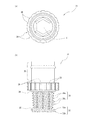
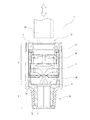
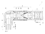
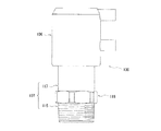
以下、図面を参照して、本発明の実施の形態について詳しく説明する。図1は、本発明の第一の実施の形態に係る管継手1の例を示す概略図である。図2は、その管継手1の接続機構5のスリーブ41の構成を示す概略図であり、図2(a)は平面図、図2(b)は正面断面図、図2(c)は側面断面図である。図3は、その管継手1の接続機構5のロック部材42の構成を示す概略図であり、図3(a)は平面図、図3(b)は正面図、図3(c)は側面断面図である。図4は、その管継手1の取付用ネジ部3の構成を示す概略図であり、図4(a)は平面図、図4(b)は正面断面図である。図5は、その取付用ネジ部3のネジ山部材30とインサート芯31との密着部の構成を示す拡大図である。図6は、その取付用ネジ部3のインサート芯31の外周部の構成を示す拡大図である。図7は、その取付用ネジ部3のインサート芯31の構成を示す概略図であり、図7(a)は平面図、図7(b)は正面図である。図8は、本発明の第二の実施の形態に係る管継手1の例を示す概略図である。図9は、本発明の第三の実施の形態に係る管継手1の例を示す概略図である。図10は、その管継手1の蓋部16を取り外した状態を示す概略図である。図11は、その管継手1の蓋部16の構成を示す概略図であり、図11(a)は平面図、図11(b)は正面図である。図12は、本発明の第四の実施の形態に係る管継手1の例を示す概略図である。図13は、本発明の第五実施の形態に係る管継手1の例を示す概略図である。
Hereinafter, embodiments of the present invention will be described in detail with reference to the drawings. FIG. 1 is a schematic view showing an example of a
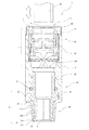
図1に示すように、本発明の第一の実施の形態に係る管継手1は、筒状に形成される本体2の後端部2bに、外部配管60を接続・固定する継手部4を備え、先端部2aに、取付用ネジ部3を備えて、内部を流体が通過する構造である。なお、外部配管60は継手部4の開口部12から軸方向に挿入される。一例として、本体2は熱安定性や寸法精度、電気特性に優れるPBT(ポリブチレンテレフタレート)を用いて構成される。符号7は、開口部12に設けられるゴム製のパッキンであり、本体2および挿入される外部配管60に隙間なく密着することにより、通過させる流体が漏れないようにシールを行う。また、開口部12が設けられる位置には、接続機構5およびパッキン7を本体2内部に保持するためのリング状のキャップ部50が設けられる。
また、取付用ネジ部3は、外周にネジ山を有するネジ山部材30を備えると共に、その内部には当該取付用ネジ部3を回動させるための回動工具を嵌入する工具連結部と、流体が通過する管路とを備える(詳細は後述)。管継手1は、取付用ネジ部3によって、外部流体機器(不図示)における流体が出入する接続孔に接続される。
このようにして、管継手1を介して外部配管60と外部流体機器とを結ぶ流体の流路が構成される。
As shown in FIG. 1, the pipe joint 1 according to the first embodiment of the present invention has a
The mounting
In this manner, a fluid flow path that connects the
ここで、外部配管60を接続・固定するために継手部4に設けられる接続機構5は、当該接続・固定機能を発揮する構成であれば足り、特にその構成は限定されるものではないが、第一の実施の形態、第二の実施の形態においては、後述のように開口部12から挿入される回動工具が貫通孔6まで到達できる構成であることが必要となる。
一例として、接続機構5は以下に示す構成が考えられる。本体2に、軸方向が本体2の軸方向と一致するようにして筒状のスリーブ41(図2参照)が内嵌されて固定される。さらに、スリーブ41に、環状のリング部43および当該リング部43から軸方向に延出する複数の延出部44を有するロック部材42(図3参照)が内嵌される。このとき、ロック部材42は、リング部43の軸方向と前記スリーブ41の軸方向とが一致するように構成されると共に、スリーブ41内を軸方向に移動可能および周方向に回動可能なように構成される。
Here, the connection mechanism 5 provided in the
As an example, the connection mechanism 5 may have the following configuration. A cylindrical sleeve 41 (see FIG. 2) is fitted and fixed to the
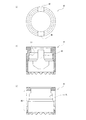
図2にスリーブ41の構成を示す(図2(a)は平面図、図2(b)は正面断面図、図2(c)は側面断面図)。スリーブ41は、筒状の壁部を貫通する切欠穴48が設けられる。本実施の形態では、切欠穴48は軸対象に二箇所設けられる。なお、切欠穴48には、ロック部材42の突起部45(後述)が係合される。なお、スリーブ41は、一例としてPOM(ポリアセタール)等の樹脂材料からなる。
2 shows a configuration of the sleeve 41 (FIG. 2A is a plan view, FIG. 2B is a front sectional view, and FIG. 2C is a side sectional view). The
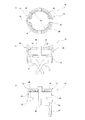
図3にロック部材42の構成を示す(図3(a)は平面図、図3(b)は正面図、図3(c)は側面断面図)。本実施の形態では、延出部44はリング部43の軸を対称に二箇所設けられる。なお、延出部44の個数は二箇所でなくてもよいが、二箇所の場合には、金型パーティングラインが2つ割りとなることによって、生産性の向上が図られる。
延出部44は、筒体を(スリットにより)2つ割りにした半筒状の形態をなし、リング部43への接続部には、周方向に伸びる切欠が形成され、これにより両延出部44は、両外方へ、弾力をもって屈曲可能となっている。
各延出部44の内周には、径方向の内方に向かって立設されるプレスツメ46が設けられる。このとき、軸中心に対向するプレスツメ46同士の間の距離D1は、挿入される外部配管60に圧接させることが可能なように、外部配管60の外径よりも小さく構成される。例えば、鋸刃状に形成することにより食い込み力、摩擦力をより高めることができる。
また、ロック部材42には、延出部44において径方向の外方に向かって立設される突起部45が設けられる。各突起部45は、対応する位置の前記切欠穴48内に侵入し、当該切欠穴48内を移動可能な状態となっている。
なお、一例として、ロック部材42は、可撓性を有する樹脂材料からなり、プレスツメ46はステンレス鋼からなる。なお、当該樹脂材料としては、POM(ポリアセタール)が強度、弾性率、耐衝撃性、摺動特性に優れており好適である。
FIG. 3 shows the configuration of the lock member 42 (FIG. 3A is a plan view, FIG. 3B is a front view, and FIG. 3C is a side sectional view). In the present embodiment, the extending
The extending
A
Further, the
As an example, the
また、接続機構5には、ロック部材42を管の抜脱方向(図1中の上方向)に向かって付勢する付勢部材47が設けられる。本実施の形態においては、付勢部材47は、ロック部材42と一体に形成される構成を備え、より具体的には、リング部43から管の挿入方向(図1中の下方向)に向かって螺旋状に延出する形状であって、リング部43の軸に対して軸対称に二箇所設けられる(図3参照)。もちろん、ロック部材42と別体に形成してもよく、コイル状等のように上記以外の形状であってもよい。
なお、各付勢部材47は、各延出部44に対応させてその下方から延出するように形成される構成を備える。
Further, the connection mechanism 5 is provided with an urging
Each urging
上記構成によって、外部配管60をロック部材42に挿入したとき、当該ロック部材42が挿入方向に押動されて、付勢部材47の先端部と対応する本体2の当接部24とが当接・摺動して、リング部43が折れ曲がることによって対向する延出部44間が拡径される作用が生じる。
その結果、対向する延出部44同士の間、特に、外部配管60の外径よりも小さく構成されている対向するプレスツメ46同士の間が拡径されて、外部配管60の外径よりも大きく拡げられるため、外部配管60が対向する延出部44の間(特に、対向するプレスツメ46同士の間)の空間部に進入することが可能となる。なお、厳密には、外部配管60がプレスツメ46に摺接しながら進入することとなる。
With the above configuration, when the
As a result, the diameter between the opposing
また、スリーブ41に延出部縮径用テーパ面51が設けられ、これに対応する当接部として、延出部縮径用テーパ面52がロック部材42に設けられる(図2、3参照)。
Also, the
その作用として、ロック部材42内に挿入されてロックされている外部配管60を抜脱方向に引動したとき、スリーブ41に内嵌されているロック部材42が外部配管60と共に抜脱方向に引動されることにより、延出部縮径用テーパ面51と、該テーパ面に対応する当接部すなわち延出部縮径用テーパ面52とが当接して摺動する。このとき、延出部縮径用テーパ面52が延出部縮径用テーパ面51から受ける力(径方向の内方へ押される力)の作用によって、延出部縮径用テーパ面52が設けられている延出部44の開口部12側の端部が径方向の内方に向かって変位する。その結果、対向する延出部44同士の間、特に、外部配管60の外径よりも小さく構成されている対向するプレスツメ46同士の間が縮径されて、当該プレスツメ46がより一層外部配管60の外周に食い込むこととなる。すなわち、外部配管60を抜脱方向に引動する力が大きければ大きいほど、プレスツメ46同士の間が一層縮径されることなり、プレスツメ46が外部配管60の外周に食い込む力すなわち外部配管60とプレスツメ46との圧接力が一層大きくなるため、前記引動力が大きくなっても外部配管60の抜脱を防止することが可能となる。
As an action, when the
続いて、管継手1に外部配管60を接続・固定する際の操作と、管継手1の動作について説明する。
外部配管60を繋ぐ前の段階では、管継手1は、図1に示すように、ロック部材42が付勢部材47の付勢力で開口部12側に向かって付勢されて静止している。
Subsequently, an operation when the
In the stage before connecting the
この図1の状態で、作業者は、外部配管60を開口部12から挿入する。このとき、外部配管60の先端部は、最初に、延出部44に設けられたプレスツメ46の開口部12側上面に当接して、スリーブ41に内嵌されているロック部材42が外部配管60によって挿入方向に押動される。これにより、ロック部材42下部に設けられた付勢部材47の先端部と本体2の当接部24とが当接し、付勢部材47が付勢力を発生させるが、当該付勢力に抗して、さらに外部配管60を押し込むと、付勢部材47の先端部と当接部24とが摺動して、リング部43が折れ曲がることによって対向する延出部44間(プレスツメ46間)が拡径される。
なお、ロック部材42のリング部43には、外部配管の進入量を規制するストッパ49が設けられているため、ロック部材42の内部において所定量以上に外部配管60が進入することはない。ただし、外部配管60よりも外径の小さい回動工具の進入は可能である。
ちなみに、上記の動作中において、外部配管60の先端部が当接する箇所は、延出部44間(プレスツメ46間)の拡径が進むにつれて、プレスツメ46の開口部12側上面から、ストッパ49へと移行する。
In this state of FIG. 1, the operator inserts the
The
Incidentally, during the above operation, the position where the tip of the
作業者が、外部配管60の挿入を停止することによって、自動的にロックが完了する。より詳しくは、強制的に拡径されている状態の延出部44が元に戻ろうとする復元力が生じるためである。
なお、付勢部材47がロック部材42をスリーブ41内において抜脱方向へ付勢する力を生じさせているため、外部配管60の挿入力を解除すると、付勢部材47がロック部材42を抜脱方向へ押動する。
When the operator stops the insertion of the
Since the urging
ちなみに、外部配管60がロックされた状態においては、パッキン7の内周と外部配管60の外周とが隙間無く密着し、パッキン7の外周と本体2の内周とが隙間無く密着するため、通過流体が外部に漏出することが防止される。
Incidentally, when the
続いて、取付用ネジ部3の構成について説明する。
図4に示すように、本実施の形態に係る取付用ネジ部3は、インサート芯31の外周に、ネジ山部材30が密着して形成されて、雄ネジとして構成される。また、ネジ山部材30のネジ山の先端部と後端部とを軸線方向において挟み込むように、インサート芯31には先端部3aの位置に大径部32が設けられ、後端部3b(後端部3bよりも先端部3a寄りの中間部でもよい)に大径部34が設けられる。
また、後端部3bに連結部35が設けられる。なお、連結部35は、別体で形成して後端部3bに接続してもよく、本実施形態のように、インサート芯31に連続して一体で形成し、後端部3bから本体2の方向へ延出するように構成してもよい。
Next, the configuration of the mounting
As shown in FIG. 4, the mounting
Further, a connecting
本実施の形態では、本体2を別体として形成しておき、連結部35に連結して、管継手1を構成する(図1参照)。なお、Oリング19によってシール性を保っている。
この構成によれば、本体2に設けられる継手部4の多品種化に対応しつつ、ネジ部(取付用ネジ部3)の共通化を図り、製造コストの削減、あるいは量産化が可能となる。
In the present embodiment, the
According to this configuration, the screw portion (mounting screw portion 3) can be made common while corresponding to the wide variety of
一方、ネジ山部材30は、インサート芯31よりも軟らかい材料で構成する。これにより、特に、ネジ山部材30をテーパネジ形状に形成する場合に顕著な効果が生じる。より具体的には、締結する際、径方向の圧縮力が作用して、軟らかい材料からなるネジ山部材30が螺合相手のネジ部(ここでは雌ネジ)の形状に対応して隙間を埋めるように変形して密着するため、シール性が格段に向上する。なお、軟らかい材料は、径方向の圧縮力によって、軸線方向のねじ込む方向およびそれと逆の方向の両方向に、いわば流出するように変形が生じてしまうが、本実施形態では、インサート芯31の先端部3aおよび後端部3bに設けられる大径部32および34によって、ネジ山部材30の両端部が挟み込まれて形成されているため、そのような変形が抑止されて、変形に起因した締結の緩みが長期にわたって防止される。
On the other hand, the
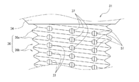
上記変形を抑止するために、変形が生じる位置、すなわちネジ山部材30の山部21aおよび谷部21bの外径位置において、大径部32および34によって挟み込むように構成することが好適である。しかし、大径部32および34の外径は、ネジ山部材30の山部21aの外径よりも大きく形成すれば、挟み込みは十分となるが、先端部3aの大径部32がネジ山部材30の山部21aよりも大径になると、雌ネジとの螺合が不可能となる。したがって、大径部34はネジ山部材30の山部21aよりも大径で、且つ大径部32はネジ山部材30の山部21aと同径である構成が、ネジ山部材30のネジ山の両端部全体に接して抑止を行うために最適であるといえる。当該構成を実現するため、本実施形態では、特に、インサート芯31の先端部3aの大径部32の外周に、ネジ山部材30のネジ山に連続するネジ山33が形成されている。すなわち、ネジ山部材30の山部21aおよび谷部21bと、ネジ山33の山部33aおよび谷部33bとが、それぞれ連続するように形成されて、一つのネジとして一体で機能させると共に、大径部32の外径を、許容範囲内で最適化(最大化)している。
In order to suppress the above deformation, it is preferable that the
加えて、本実施形態では、図5に示すように、インサート芯31の外周形状が、ネジ山部材30のネジ山の山および谷(山部21aおよび谷部21b)と山および谷の位置が軸線方向において一致するネジ形状(山部36aおよび谷部36b)を有する。それによって、インサート芯31に相対的に硬い材料(例えば、高強度樹脂)を使用し、その外周のネジ山部材30に相対的に軟らかい材質(例えば、樹脂)を均一に成形することにより、工具を使用してインサート芯31を回動させても破壊されることなく、且つネジ締めに伴う高荷重によるネジ山部材30のネジ山の欠落・変形・経年変化等がない構造を可能にする。
In addition, in the present embodiment, as shown in FIG. 5, the outer peripheral shape of the
さらに、図6に示すようにインサート芯31の外周には、ネジ形状を構成するネジ溝36bを周方向に分断する凸状のリブ37が複数形成される。また、図7(図7(a)は平面図、図7(b)は正面図)に示すようにインサート芯31の外周には、軸線方向に延びる複数の突起部38、および複数の溝部39が形成され、ネジ山部材30の延出部22によって被覆される(図4参照)。
これらによって、締結の際、インサート芯31とネジ山部材30との間に高荷重が加わっても、特に、周方向へ相互に位置ずれ・変形することが防止でき、経年変化も防止できる。
Further, as shown in FIG. 6, a plurality of
Thus, even when a high load is applied between the
ここで、使用材料の例として、インサート芯31は、ポリアミドMXD6樹脂もしくはポリフェニレンサルファイド樹脂等が好適である。ポリアミドMXD6樹脂は、強度、耐熱性、弾性強度、耐薬品性、寸法安定性に優れ、工具の嵌入・使用が可能であり、ネジ部材として用いられる場合の高荷重にも耐えられる材料で、ガラス繊維を50%含ませることにより、さらに性能を向上させることができる。最適材料はReny(三菱瓦斯化学株式会社登録商標)である。また、ポリフェニレンスルファイド樹脂は、強度や剛性がきわめて高く、耐磨耗性にも優れる。ポリアミドMXD6樹脂よりも靭性が低いものの、食品安全性が高く、アメリカ食品医薬品局および米国科学財団では食品機器厨房用品や水道飲用水に接触する部分への使用を認可しているため、ネジの使用用途によっては最適材料となる。
一方、ネジ山部材30は、ポリブチレンテレフタレート樹脂等が好適である。熱安定性や寸法精度、電気特性に優れるため、外周のネジ部分の材料として適している。
Here, as an example of the material used, the
On the other hand, the
上記構成を備えることによって、従来の管継手では金属材料を用いて形成していた取付用ネジ部を、樹脂材料で形成することが可能となり、取り付け時の高トルクに耐えられる構成を実現しつつ、製造コストを低下させることが可能となる。
また、本実施形態に係る取付用ネジ部3は、高いシール性と長期にわたる緩み防止が達成可能であるため、管用ネジとして好適である。さらに、取付用ネジ部3を管用テーパ雄ネジとしてJISB203等の規格を適用して形成することで、汎用性を高めることが可能となる。
By providing the above-described configuration, it is possible to form a mounting screw portion that has been formed using a metal material in a conventional pipe joint with a resin material, while realizing a configuration that can withstand high torque during mounting. Thus, the manufacturing cost can be reduced.
Further, the mounting
ところで、従来、管継手の管用ネジは、内部に管路を備えるため、回動用の工具を連結するための工具連結部は外周部に設けられていた(図14参照)。そのため、管継手を狭い場所に取り付ける際に、回動工具を工具連結部に連結させることができない、あるいは連結はできても回転させることができない等の事象がしばしば発生し、取り付けが不可能になるといった課題があった。 By the way, conventionally, since the pipe thread of a pipe joint is provided with a pipe line inside, the tool connection part for connecting the tool for rotation was provided in the outer peripheral part (refer FIG. 14). For this reason, when fitting a pipe joint in a narrow space, it often happens that the rotating tool cannot be connected to the tool connecting part, or that the connecting tool cannot be rotated even if it can be connected. There was a problem of becoming.
さらに、本実施形態のように、取付用ネジ部3の外周部すなわちネジ山部材30が軟らかい材料からなる場合、工具連結部を形成するには不適である。その一方で、インサート芯31をネジ山部材30の延出部22よりも、後端部3bの方向に長く延出させて、その延出部に工具連結部を形成しようとすると、コンパクト性に欠けることとなる。
Furthermore, as in the present embodiment, when the outer peripheral portion of the mounting
そこで、本実施形態においては、管路と工具連結部とを兼用することが可能な構造を取付用ネジ部3の内部に設けることによって、上記の課題の解決を可能とした。
より具体的には、取付用ネジ部3のインサート芯31の内部に、管路と取付用ネジ部3を回転させる回動工具を嵌入するための工具連結部とを兼用する断面が多角形の貫通孔6を、当該インサート芯31の径の中心を通って軸線方向に貫通するように設けている。
また、継手部4の開口部12は、回動工具を挿入して回動させることが可能な大きさに形成される。
Therefore, in the present embodiment, the above-described problem can be solved by providing a structure capable of serving both as a pipe line and a tool connecting portion inside the mounting
More specifically, the polygonal cross-section that serves both as a pipe connection and a tool connecting portion for inserting a turning tool for rotating the mounting
Moreover, the opening
一例として、貫通孔6は、軸線方向の一部もしくは全部を断面が正六角形に形成する。それによって、汎用六角レンチを使用して締結することが可能となる。ただし、貫通孔6の断面形状は正六角形には限定されず、他の多角形(例えば星型のような形状も含む)、もしくは楕円等のように正円以外の曲線からなる形状であってもよい。
As an example, the through-
従来は、管継手を取り付ける際に、外周部に設けられていた工具連結部にスパナ等の回動工具を連結して、取付用ネジ部を回動させ、取り付けていたのに対し、上記構成を備えることによって、六角レンチのような回動工具を取付用ネジ部3の内部に軸線方向に挿入し、連結(嵌入)および回動が可能となるため、従来のスパナのように径方向に広い回動用空間を必要とせず、非常に狭い場所であっても、取付用ネジ部3を回動させて、管継手1を取り付けることが可能となる。さらに、電動回転工具等の使用も可能となるため、短時間に且つ容易に取り付けることが可能となる。
Conventionally, when attaching a pipe joint, a rotating tool such as a spanner is connected to a tool connecting part provided on the outer periphery, and the mounting screw part is rotated and attached. Since a rotating tool such as a hexagon wrench can be inserted into the mounting
続いて、第二の実施の形態に係る管継手1について説明する。
図8に示すように、前記第一の実施の形態との相違点として、取付用ネジ部3の後端部3bに連結部35が設けられない構成であると共に、筒状の本体2とネジ山部材30とが前記樹脂を用いて一体に形成される構成である。
この構成によれば、部品点数の削減および製造工程の削減が可能となるため、製造コストをより低く抑えることが可能となる。
Then, the pipe joint 1 which concerns on 2nd embodiment is demonstrated.
As shown in FIG. 8, the difference from the first embodiment is that the connecting
According to this configuration, it is possible to reduce the number of parts and the manufacturing process, and thus it is possible to further reduce the manufacturing cost.
続いて、第三の実施の形態に係る管継手1について説明する。
前記第一の実施の形態、第二の実施の形態との相違点として、本実施形態の管継手1は、開口部12の中心軸と、管路すなわち貫通孔6の中心軸とが一致しない構成を有する。
より具体的には、図9に示すように、取付用ネジ部3の中心軸(ここでは貫通孔6の中心軸と一致)と、本体2の中心軸とが一致するように、取付用ネジ部3と本体2とが連結され(第二の実施形態のように一体形成でもよい)、本体2の中心軸と継手部4の中心軸とが0度ではない角度(ここでは90度)をなすように、本体2と継手部4とが連結(本実施形態では一体に形成)される。
Next, the pipe joint 1 according to the third embodiment will be described.
As a difference from the first embodiment and the second embodiment, in the
More specifically, as shown in FIG. 9, the mounting
上記の構成を有する管継手1は、一般に、L字状継手あるいはLタイプ継手等と称されるものであるが、前記第一の実施の形態、第二の実施の形態と相違して、継手部4の開口部12から回動工具を挿入して、工具連結部すなわち貫通孔6に嵌入させることが不可能である。
そこで、本実施形態に特徴的な構成として、回動工具を挿入して回動させることが可能な大きさの工具挿入口14が本体2に設けられる。もちろん、継手部4に設けてもよい。
The pipe joint 1 having the above-described configuration is generally called an L-shaped joint or an L-type joint, but the joint is different from the first embodiment and the second embodiment. It is impossible to insert the turning tool from the
Therefore, as a characteristic configuration of the present embodiment, the
本実施形態では、図9〜図11に示すように、工具挿入口14は、その中心軸が、貫通孔6の中心軸と一致するように本体2に設けられる。さらに、貫通孔6の中心軸と一致するように本体2の内部に設けられる管路17は、回動工具の挿入路を兼用することとなる。このようにして、工具挿入口14から管路17を経て貫通孔6に至る、回動工具の挿入路が構成される。
なお、回動工具を挿入して回動させることが可能でさえあれば、工具挿入口14および管路17は、貫通孔6に対して中心軸を一致させることは必須ではなく、形状についても特に限定されるものではない。
In the present embodiment, as shown in FIGS. 9 to 11, the
As long as the turning tool can be inserted and rotated, it is not essential that the
一方、工具挿入口14は、流体を通過させる際に、シールする必要があることから、当該工具挿入口14を密閉および開放することが可能な蓋部16が設けられる。本実施形態では、工具挿入口14と蓋部16との間にOリング18を設けて流体が漏れないようにシールを行っている。ここで、図9は蓋部16が取り付けられた状態の図であり、図10は蓋部16が取り外された状態の図である。
なお、蓋部16と工具挿入口14との締結方法は、ネジによる螺合方式としたが、これに限定されるものではない。また、締結に使用する工具もドライバー、レンチ等、どのようなものであってもよく、蓋部16の上面を該工具に対応した工具連結用形状とすればよい。
図11(図11(a)は平面図、図11(b)は正面図)に示すように、本実施形態においては、汎用六角レンチ61により回動可能なように、蓋部16の上面の工具連結用形状を正六角形の溝としている(図11中の符号20)。なお、その溝(正六角形)の大きさと、貫通孔6の断面(正六角形)の大きさとを一致させれば、共通の回動工具(六角レンチ)によっていずれも回動させることが可能となるため、非常に効率的である。
On the other hand, since the
In addition, although the fastening method of the
As shown in FIG. 11 (FIG. 11 (a) is a plan view and FIG. 11 (b) is a front view), in the present embodiment, the upper surface of the
なお、本体2と取付用ネジ部3とは相互に同軸で回動可能に連結される構成であってもよい。この構成によれば、例えば、狭い場所における取り付け時等、継手部4を回動させることが出来ない場合であっても、継手部4の向きを固定したまま、取付用ネジ部3のみを回動させることが可能となるため、管継手1の取り付けを行うことが可能となる。
The
続いて、第四の実施の形態に係る管継手1について説明する。
前記第三の実施の形態との相違点として、本実施形態の管継手1は、継手部4を複数備える構成である。
例えば、図12に示すように、本体2に二つの継手部4が連結される(本実施形態では一体に形成される)構成を有し、一般に、T字状継手あるいはTタイプ継手等と称されるものである。
なお、継手部4の数が異なる点以外は、上記第三の実施の形態と同様の構成を備えるものであるため、説明を省略する。もちろん、継手部4が三つ以上である構成も考えられる。
Then, the pipe joint 1 which concerns on 4th embodiment is demonstrated.
As a difference from the third embodiment, the
For example, as shown in FIG. 12, it has a configuration in which two
Since the configuration is the same as that of the third embodiment except that the number of
続いて、第五の実施の形態に係る管継手1について説明する。
本実施形態の管継手1は、前記第三の実施の形態を基本構成とし、継手部4と取付用ネジ部3との間に、通過流体の流量を調整する流量調整機構9が設けられる構成である。
流量調整機構9については、様々な構成が考えられるが、例えば、図13に示すように、先端部にV字状の切欠部56が設けられたニードル55を、調整ダイヤル57を用いて軸方向に移動させて、当該切欠部56とチェック弁58とによって形成される流路の面積を拡大もしくは縮小することによって、通過流体の流量を調整する機構である。なお、図13中、矢印Aが制御流、矢印Bが自由流の流れ方向を示す。
Then, the pipe joint 1 which concerns on 5th embodiment is demonstrated.
The
For the flow rate adjusting mechanism 9, various configurations are conceivable. For example, as shown in FIG. 13, a
以上説明したように、本発明によれば、従来の管継手では金属材料を用いて形成していた取付用ネジ部を樹脂材料で形成することが可能となり、その結果、取り付け時のトルクに耐えられる構成を実現しつつ、製造コストを低下させることが可能となる。
その一方で、取付用ネジ部のネジ山部材に軟らかい材料を用いて、螺合するネジとの密着性を高め、締結部のシール性を向上させることが可能であると共に、当該ネジ山部材が必要以上に変形してしまうことを抑止し、変形に起因した締結の緩みを長期にわたって防止することが可能となる。
さらに、取付用ネジ部をねじ込むための回動工具を連結するための工具連結部を、当該取付用ネジ部の外周ではなく、内部に設ける構成を実現することによって、狭い取り付け場所においても、従来のように回動工具が回動できないことによる取り付け不能を回避でき、容易に取り付けることが可能となる。
As described above, according to the present invention, it is possible to form a mounting screw portion made of a metal material in a conventional pipe joint from a resin material, and as a result, endure the torque at the time of mounting. The manufacturing cost can be reduced while realizing the configuration to be achieved.
On the other hand, using a soft material for the thread member of the mounting screw part, it is possible to improve the adhesion with the screw to be screwed together and improve the sealing performance of the fastening part. It is possible to suppress the deformation more than necessary, and to prevent loosening due to the deformation over a long period of time.
Further, by realizing a configuration in which a tool connecting portion for connecting a turning tool for screwing the mounting screw portion is provided not inside the outer periphery of the mounting screw portion, but also in a narrow mounting place, Thus, it is possible to avoid the mounting failure due to the fact that the rotating tool cannot be rotated, and it is possible to easily attach the rotating tool.
1 管継手
2 本体
3 取付用ネジ部
4 継手部
5 接続機構
6 貫通孔
7 パッキン
9 流量調整機構
12 開口部
14 工具挿入口
16 蓋部
18、19 Oリング
30 ネジ山部材
31 インサート芯
32、34 大径部
33 ネジ山
35 連結部
41 スリーブ
42 ロック部材
60 外部配管
DESCRIPTION OF
Claims (17)
前記取付用ネジ部は、外周にネジ山を有し、内部に該取付用ネジ部を回動させる回動工具が嵌入可能な工具連結部および流体が通過する管路を有し、
前記継手部は、前記外部配管が挿入される開口部を備え、
前記開口部の中心軸と、前記管路の中心軸とが一致しない構成であって、
前記本体に前記回動工具を挿入し回動させることが可能な大きさの工具挿入口が設けられ、
該工具挿入口の密閉および開放が可能な蓋部が設けられること
を特徴とする管継手。 One end of the main body is provided with one or a plurality of joints for connecting external pipes, and the other end is provided with a mounting screw part, and a pipe joint through which fluid passes,
The installation screw part has a screw thread on the outer periphery, have a conduit interior turning tool to rotate the screw part for with said mounting to be fitted a tool connecting part and a fluid passes,
The joint portion includes an opening into which the external pipe is inserted,
The central axis of the opening and the central axis of the conduit do not coincide with each other,
A tool insertion opening of a size capable of inserting and rotating the rotating tool in the main body is provided,
A pipe joint characterized by being provided with a lid part capable of sealing and opening the tool insertion slot .
前記取付用ネジ部は、外周にネジ山を有し、内部に該取付用ネジ部を回動させる回動工具が嵌入可能な工具連結部および流体が通過する管路を有し、
前記取付用ネジ部は、軸方向の中心にインサート芯を備え、
前記インサート芯の外周に、該インサート芯よりも軟らかい材料からなる雄ネジ状の前記ネジ山を有するネジ山部材が密着して形成されること
を特徴とする管継手。 One end of the main body is provided with one or a plurality of joints for connecting external pipes, and the other end is provided with a mounting screw part, and a pipe joint through which fluid passes,
The mounting screw portion has a thread on the outer periphery, and has a tool connecting portion into which a turning tool for rotating the mounting screw portion can be inserted and a conduit through which fluid passes,
The mounting screw portion includes an insert core at the center in the axial direction,
On the outer periphery of the insert core, a thread member having the male thread-like thread made of a material softer than the insert core is formed in close contact with the insert core.
Pipe fittings characterized by
を特徴とする請求項1または請求項2記載の管継手。 The part or the whole of the pipe line is formed in the tool connecting part capable of receiving a turning tool for turning the mounting screw part. Item 2. The pipe joint according to Item 2.
該開口部は、前記回動工具を挿入し回動させることが可能な大きさに形成されること
を特徴とする請求項2または請求項3記載の管継手。 The joint portion includes an opening into which the external pipe is inserted,
The opening is formed in a size that allows the rotating tool to be inserted and rotated.
The pipe joint according to claim 2 or 3, wherein
を特徴とする請求項1〜4のいずれか一項記載の管継手。 The pipe joint according to any one of claims 1 to 4, wherein the main body and the mounting screw part are coaxially connected to each other so as to be rotatable.
を特徴とする請求項1〜5のいずれか一項記載の管継手。 The pipe joint according to any one of claims 1 to 5, further comprising a flow rate adjusting mechanism that adjusts a flow rate of a passing fluid between the joint portion and the mounting screw portion.
前記インサート芯の外周に、該インサート芯よりも軟らかい材料からなる雄ネジ状の前記ネジ山を有するネジ山部材が密着して形成されること
を特徴とする請求項1記載の管継手。 The mounting screw portion includes an insert core at the center in the axial direction,
The outer periphery of the insert core, the pipe joint of claim 1, wherein the screw thread member having a screw thread of the male threaded consisting of softer material than the insert core is formed in close contact.
を特徴とする請求項2〜7のいずれか一項記載の管継手。 The pipe joint according to any one of claims 2 to 7 , wherein the pipe core is provided in the insert core.
を特徴とする請求項3〜8のいずれか一項記載の管継手。 The pipe joint according to any one of claims 3 to 8, wherein a portion of the pipe line that also serves as the tool connecting portion is formed in a through-hole shape having a polygonal or elliptical cross section.
を特徴とする請求項2〜9のいずれか一項記載の管継手。 The screw thread member is configured to be sandwiched between a front end portion of the insert core and a rear end portion or a large diameter portion provided at an intermediate portion closer to the front end portion than the rear end portion. The pipe joint according to any one of 2 to 9 .
を特徴とする請求項10記載の管継手。 The pipe joint according to claim 10, wherein a thread continuous with the thread of the thread member is formed on an outer periphery of the large-diameter portion of the tip.
を特徴とする請求項2〜11のいずれか一項記載の管継手。 The pipe joint according to any one of claims 2 to 11, wherein the thread member is formed in a taper screw shape.
を特徴とする請求項2〜12のいずれか一項記載の管継手。 Peripheral shape of the insert core is any one of claims 2-12 for the peaks and valleys and the peaks and valleys of the position of the threads of the screw thread member and having a thread shape which matches in the axial direction The described pipe joint.
を特徴とする請求項13記載の管継手。 The pipe joint according to claim 13, wherein a plurality of ribs are formed on an outer periphery of the insert core to divide a thread groove forming the thread shape in a circumferential direction.
を特徴とする請求項2〜14のいずれか一項記載の管継手。 The pipe joint according to any one of claims 2 to 14, wherein a plurality of protrusions or a plurality of grooves extending in the axial direction are formed on an outer periphery of the insert core.
を特徴とする請求項2〜15のいずれか一項記載の管継手。 The pipe joint according to any one of claims 2 to 15, wherein the insert core is made of polyamide MXD6 resin or polyphenylene sulfide resin.
を特徴とする請求項2〜16のいずれか一項記載の管継手。 The pipe joint according to any one of claims 2 to 16, wherein the thread member formed in close contact with the insert core is configured by using polybutylene terephthalate resin.
Priority Applications (6)
| Application Number | Priority Date | Filing Date | Title |
|---|---|---|---|
| JP2008273536A JP4355019B1 (en) | 2008-10-23 | 2008-10-23 | Pipe fitting |
| US12/504,118 US20100102555A1 (en) | 2008-10-23 | 2009-07-16 | Tube fitting |
| TW098124170A TW201017021A (en) | 2008-10-23 | 2009-07-17 | Tube fitting |
| EP09251826A EP2180227A1 (en) | 2008-10-23 | 2009-07-17 | Tube fitting |
| CN200910168795A CN101725779A (en) | 2008-10-23 | 2009-09-03 | Tube fitting |
| KR1020090085829A KR20100045368A (en) | 2008-10-23 | 2009-09-11 | Tube fitting |
Applications Claiming Priority (1)
| Application Number | Priority Date | Filing Date | Title |
|---|---|---|---|
| JP2008273536A JP4355019B1 (en) | 2008-10-23 | 2008-10-23 | Pipe fitting |
Publications (2)
| Publication Number | Publication Date |
|---|---|
| JP4355019B1 true JP4355019B1 (en) | 2009-10-28 |
| JP2010101431A JP2010101431A (en) | 2010-05-06 |
Family
ID=41314421
Family Applications (1)
| Application Number | Title | Priority Date | Filing Date |
|---|---|---|---|
| JP2008273536A Expired - Fee Related JP4355019B1 (en) | 2008-10-23 | 2008-10-23 | Pipe fitting |
Country Status (6)
| Country | Link |
|---|---|
| US (1) | US20100102555A1 (en) |
| EP (1) | EP2180227A1 (en) |
| JP (1) | JP4355019B1 (en) |
| KR (1) | KR20100045368A (en) |
| CN (1) | CN101725779A (en) |
| TW (1) | TW201017021A (en) |
Families Citing this family (3)
| Publication number | Priority date | Publication date | Assignee | Title |
|---|---|---|---|---|
| KR101131386B1 (en) * | 2011-09-21 | 2012-04-03 | 심혁수 | Rotary joint |
| CN105546124B (en) * | 2013-10-23 | 2017-10-27 | 南安市丽迪家居用品有限公司 | A kind of valve seat |
| DE102018114918A1 (en) * | 2018-06-21 | 2019-12-24 | Norma Germany Gmbh | Connection arrangement for forming a fluid-carrying connection |
Family Cites Families (4)
| Publication number | Priority date | Publication date | Assignee | Title |
|---|---|---|---|---|
| JPS569727Y2 (en) * | 1977-08-29 | 1981-03-04 | ||
| US4923221A (en) * | 1989-01-25 | 1990-05-08 | Cameron Iron Works U.S.A., Inc. | Safety connection into passages in a tubular body |
| US4926898A (en) * | 1989-10-23 | 1990-05-22 | Sampey Ted J | Safety choke valve |
| JP4839157B2 (en) | 2006-09-06 | 2011-12-21 | 積水化学工業株式会社 | Pipe fitting |
-
2008
- 2008-10-23 JP JP2008273536A patent/JP4355019B1/en not_active Expired - Fee Related
-
2009
- 2009-07-16 US US12/504,118 patent/US20100102555A1/en not_active Abandoned
- 2009-07-17 EP EP09251826A patent/EP2180227A1/en not_active Withdrawn
- 2009-07-17 TW TW098124170A patent/TW201017021A/en unknown
- 2009-09-03 CN CN200910168795A patent/CN101725779A/en active Pending
- 2009-09-11 KR KR1020090085829A patent/KR20100045368A/en not_active Application Discontinuation
Also Published As
| Publication number | Publication date |
|---|---|
| TW201017021A (en) | 2010-05-01 |
| KR20100045368A (en) | 2010-05-03 |
| EP2180227A1 (en) | 2010-04-28 |
| JP2010101431A (en) | 2010-05-06 |
| CN101725779A (en) | 2010-06-09 |
| US20100102555A1 (en) | 2010-04-29 |
Similar Documents
| Publication | Publication Date | Title |
|---|---|---|
| RU2643890C2 (en) | Sleeve assembly for pipeline fitting | |
| EP2899441B1 (en) | Pipe joint structure | |
| JP4330030B1 (en) | Screw, fastening system, pipe joint, and method for manufacturing the screw | |
| KR102121628B1 (en) | Push to connect conduit fitting with ferrule | |
| JP4355020B1 (en) | Pipe fitting | |
| WO2013168306A1 (en) | Pipe joint | |
| JP4906973B1 (en) | Pipe fitting | |
| JP4355019B1 (en) | Pipe fitting | |
| JP5269178B2 (en) | How to assemble pipe fittings | |
| JP6112842B2 (en) | Pipe joint structure | |
| JP4852368B2 (en) | Pipe fitting | |
| JP2008038924A (en) | Pipe joint | |
| US20030197378A1 (en) | Sealing compression ferrule for plumbing connection fitting | |
| US10344894B2 (en) | Retention and anti-rotation for bulkhead fittings | |
| JP4597889B2 (en) | Pipe fitting | |
| CN108443608B (en) | Pipe joint | |
| WO2011001376A1 (en) | Pipe coupling | |
| JP2008045598A (en) | Pipe fitting | |
| CN213576133U (en) | Three-way joint | |
| JP4810267B2 (en) | Pipe fitting | |
| JP6813183B2 (en) | Assembling method of pipe fittings and pipe fittings | |
| JP2023129890A (en) | Pipe joint | |
| JP2010106964A (en) | Joint for connecting different type pipes | |
| JP3107298U (en) | Detachment prevention type rotary flexible fitting | |
| JPH0113904Y2 (en) |
Legal Events
| Date | Code | Title | Description |
|---|---|---|---|
| TRDD | Decision of grant or rejection written | ||
| A01 | Written decision to grant a patent or to grant a registration (utility model) |
Free format text: JAPANESE INTERMEDIATE CODE: A01 |
|
| A61 | First payment of annual fees (during grant procedure) |
Free format text: JAPANESE INTERMEDIATE CODE: A61 Effective date: 20090730 |
|
| R150 | Certificate of patent or registration of utility model |
Free format text: JAPANESE INTERMEDIATE CODE: R150 Ref document number: 4355019 Country of ref document: JP Free format text: JAPANESE INTERMEDIATE CODE: R150 |
|
| FPAY | Renewal fee payment (event date is renewal date of database) |
Free format text: PAYMENT UNTIL: 20120807 Year of fee payment: 3 |
|
| FPAY | Renewal fee payment (event date is renewal date of database) |
Free format text: PAYMENT UNTIL: 20130807 Year of fee payment: 4 |
|
| R250 | Receipt of annual fees |
Free format text: JAPANESE INTERMEDIATE CODE: R250 |
|
| R250 | Receipt of annual fees |
Free format text: JAPANESE INTERMEDIATE CODE: R250 |
|
| R250 | Receipt of annual fees |
Free format text: JAPANESE INTERMEDIATE CODE: R250 |
|
| R250 | Receipt of annual fees |
Free format text: JAPANESE INTERMEDIATE CODE: R250 |
|
| R250 | Receipt of annual fees |
Free format text: JAPANESE INTERMEDIATE CODE: R250 |
|
| R250 | Receipt of annual fees |
Free format text: JAPANESE INTERMEDIATE CODE: R250 |
|
| R250 | Receipt of annual fees |
Free format text: JAPANESE INTERMEDIATE CODE: R250 |
|
| R250 | Receipt of annual fees |
Free format text: JAPANESE INTERMEDIATE CODE: R250 |
|
| LAPS | Cancellation because of no payment of annual fees |