JP4354287B2 - Fishing rod case - Google Patents
Fishing rod case Download PDFInfo
- Publication number
- JP4354287B2 JP4354287B2 JP2004021512A JP2004021512A JP4354287B2 JP 4354287 B2 JP4354287 B2 JP 4354287B2 JP 2004021512 A JP2004021512 A JP 2004021512A JP 2004021512 A JP2004021512 A JP 2004021512A JP 4354287 B2 JP4354287 B2 JP 4354287B2
- Authority
- JP
- Japan
- Prior art keywords
- fishing rod
- case
- bottom cup
- cup
- case body
- Prior art date
- Legal status (The legal status is an assumption and is not a legal conclusion. Google has not performed a legal analysis and makes no representation as to the accuracy of the status listed.)
- Expired - Fee Related
Links
Images

Landscapes
- Purses, Travelling Bags, Baskets, Or Suitcases (AREA)
Description
本発明は、釣竿を収納する釣竿ケースに関する。 The present invention relates to a fishing rod case that houses a fishing rod.
釣人は、釣竿を衝撃から守り、また、海水で濡らすことなく運搬するために釣竿を釣竿ケースに収納する。
そして、従来、釣竿ケースは、接地衝撃から釣竿を保護するため、ケース本体(胴部)の底部に樹脂成形品のボトムカップ(底皿体)を装着してケース本体の底部を塞ぎ、また、ケース本体に防水素材を用いたり防水構造のファスナーを用いて、釣竿ケース内部への水の浸入を防止している。
The angler stores the fishing rod in a fishing rod case in order to protect the fishing rod from impact and transport it without getting wet with seawater.
Conventionally, in order to protect the fishing rod from a grounding impact, the fishing rod case is attached with a bottom cup (bottom plate body) of a resin molded product at the bottom of the case main body (trunk) to close the bottom of the case main body, A waterproof material is used for the case body and a waterproof zipper is used to prevent water from entering the fishing rod case.
しかし、釣竿ケースは、筒体に成形したケース本体の底部をボトムカップ内に差し込んで縫糸やリベット,ネジ等で止着した構造上、雨や飛沫が釣竿ケースにかかると、ケース本体の外周を伝った水がボトムカップとの止着部の隙間から釣竿ケース内に浸入してしまう虞があった。
そして、一度釣竿ケース内に水が浸入してまうと、容易に水を排水させることができないのが実情である。
However, the fishing rod case has a structure in which the bottom of the case body molded into a cylindrical body is inserted into the bottom cup and fastened with sewing threads, rivets, screws, etc. There is a risk that the transmitted water may enter the fishing rod case through the gap between the bottom cup and the fastening portion.
And the situation is that once water enters the fishing rod case, it cannot be drained easily.
また、特許文献1には、ボトムカップの底部に複数の水抜き孔を設けた釣竿ケースが開示されている。
しかし乍ら、斯様にボトムカップの底部に水抜き孔を設けると、逆に水抜き孔から釣竿ケース内に水が多量に浸入してしまい、好ましい構造とはいえなかった。
本発明は斯かる実情に鑑み案出されたもので、ボトムカップとケース本体の止着部の隙間から水が浸入しても、水が釣竿ケース内に浸入する虞のない釣竿ケースを提供することを目的とする。
However, if a drain hole is provided at the bottom of the bottom cup in this manner, a large amount of water enters the fishing rod case from the drain hole, which is not a preferable structure.
The present invention has been devised in view of such circumstances, and provides a fishing rod case in which water does not enter the fishing rod case even if water enters from the gap between the bottom cup and the fastening portion of the case body. For the purpose.
斯かる目的を達成するため、請求項1に係る発明は、筒状に成形したケース本体の底部をボトムカップ内に差し込んで止着した釣竿ケースに於て、上記ケース本体の底部の内周に内蓋を装着し、当該内蓋でケース本体の底部を閉塞すると共に、上記ボトムカップの内側底部に突部を突設し、当該突部を除く部位に排水孔を設けたことを特徴とする。
そして、請求項2に係る発明は、請求項1に記載の釣竿ケースに於て、上記ボトムカップの底部と内蓋との間に、間隙を設けたことを特徴とする。
In order to achieve such an object, the invention according to
The invention according to claim 2, At a fishing rod case according to
また、請求項3に係る発明は、筒状に成形したケース本体の底部をボトムカップ内に差し込んで止着した釣竿ケースに於て、上記ボトムカップの側壁の内側に、当該側壁に沿って支持壁を立設し、ケース本体の底部を当該支持壁と側壁との間の間隙に差し込んで、ケース本体の底部と支持壁を止着すると共に、ボトムカップに上記間隙と連通する排水孔を設けたことを特徴とする。 According to a third aspect of the present invention, there is provided a fishing rod case in which a bottom portion of a case body formed into a cylindrical shape is inserted into a bottom cup and fastened, and is supported on the inside of the side wall of the bottom cup along the side wall. A wall is erected, the bottom of the case body is inserted into the gap between the support wall and the side wall, and the bottom of the case body and the support wall are fixed, and a drain hole communicating with the gap is provided in the bottom cup. It is characterized by that.
各請求項に係る発明によれば、雨や飛沫が釣竿ケースにかかって、ケース本体の外周を伝った水がボトムカップとの止着部の隙間から内部に浸入しても、水が釣竿ケース内に浸入することがなく、釣竿ケースの確実な防水が可能となった。
また、請求項1及び請求項2に係る発明によれば、ボトムカップ内部に浸入した水を、突部の周辺部に集めて排水孔から速やかに排水させることができる利点を有する。
According to the invention according to each claim, even if rain or splash is applied to the fishing rod case and the water that has traveled along the outer periphery of the case main body enters the inside through the gap between the bottom cup and the fastening portion, the water remains in the fishing rod case. The fishing rod case can be reliably waterproofed without entering inside.
Moreover, according to the invention which concerns on
以下、本発明の実施形態を図面に基づいて詳細に説明する。
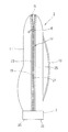
図1及び図2は請求項1及び請求項2に係る釣竿ケースの一実施形態を示し、図1に於て、1は所定形状に裁断された1枚のシートを筒状に屈曲形成した釣竿ケース3のケース本体(胴部)で、図2に示すようにその底部5は、ケース本体1の成形材料より剛性の大きい樹脂材料で形成された断面コ字状のボトムカップ(底皿体)7内に差し込まれて、当該ボトムカップ7の側壁9に全周が縫糸11で縫着されて止着されている。
Hereinafter, embodiments of the present invention will be described in detail with reference to the drawings.
1 and 2 show an embodiment of a fishing rod case according to
ケース本体1を形成するシートは、所定形状に裁断した1枚のポリウレタンやエチレン酢酸ビニル等の合成樹脂やゴム等の発泡材(独立気泡発泡材または連続気泡発泡材)の表裏に、ナイロンやポリプロピレン等の薄い外布と内布を添設した積層構造をなし、ケース本体1の背中当接面にショルダーベルト13や図示しない手提げ用の取っ手が取り付き、また、ケース本体1の一側面に図示しない小物用のサイドポケットが取り付けられている。
The sheet forming the
そして、ケース本体1に開口する釣竿取出し口15に、スライダー16の操作で当該釣竿取出し口15をケース本体1の頂部からボトムカップ7に亘って開閉するファスナー(スライドファスナー)17が取り付けられている。
ファスナーエレメント19,21が取り付くファスナー17の一対のファスナーテープ23,25は、例えばポリエステル繊維等の合成樹脂繊維を織成または編成して布状に形成され、夫々の裏面側に合成樹脂シートを溶着した防水用のコーティング層が設けられた防水構造となっている。
A fastener (slide fastener) 17 that opens and closes the
The pair of
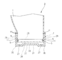
図2はケース本体1が止着されたボトムカップ7の断面図を示し、図中、27はケース本体1の底部5を閉塞する断面コ字状の内蓋で、当該内蓋27は、ボトムカップ7と同一材料を用いてボトムカップ7より薄肉に形成されている。そして、内蓋27はケース本体1の底部5の内周に配置されてケース本体1との境界からの水の浸入が防止され、その側壁29が底部5の周壁に全周に亘って縫糸11で止着されている。
FIG. 2 shows a cross-sectional view of the
そして、既述したようにケース本体1の底部5は、ボトムカップ7内に差し込まれてその側壁9に縫糸11で止着されているが、前記内蓋27とボトムカップ7の底部31との間に間隙33を空けて、ケース本体1の底部5がボトムカップ7に止着されている。
また、ボトムカップ7の底部31の四隅には、リング状の支持脚35が下方へ一体に突設され、更に各支持脚35の中央に、上記間隙33と連通する排水孔37が夫々設けられている。
As described above, the
Further, ring-
尚、排水孔37から地面の水をボトムカップ7内に吸い上げてしまうことがないように、排水孔37の外側開口部は、支持脚35の地面に接地する最下部より上側に形成されている。
そして、ボトムカップ7の底部31の中央部分には、釣竿ケース3の上方へ突出する平面視円形状の平坦な突部39が設けられており、前記排水孔37は、夫々、当該突部39の周辺部に配置された構造となっている。
In order to prevent the ground water from being sucked into the
A
尚、上記突部39は内蓋27に当接せず、当該突部39と内蓋27との間に間隙33が確保されている。また、排水孔は、ボトムカップ7の底部31に近い側壁9に設けてもよい。
本実施形態はこのように構成されているから、スライダー16の操作で、ファスナー17が釣竿ケース3の釣竿取出し口15をケース本体1の頂部からボトムカップ7に亘って開閉する。
The
Since the present embodiment is configured as described above, the
従って、釣人は釣竿取出し口15から釣竿を取り出し、また、釣竿取出し口15から釣竿を釣竿ケース3内に収納すればよく、収納された釣竿は釣竿ケース3内で内蓋27上に載置される。
そして、ボトムカップ7と内蓋27が接地衝撃から釣竿ケース3内の釣竿を保護し、また、防水素材を用いたケース本体1と防水構造のファスナー17によって防水が図られるが、ケース本体1の底部5が縫糸11によってボトムカップ7に止着されているため、雨や飛沫が釣竿ケース3にかかると、従来と同様、ケース本体1の外周を伝って水がボトムカップ7との止着部の隙間からボトムカップ7の内部に浸入する。
Therefore, the angler only has to take out the fishing rod from the
The
しかし、本実施形態に係る釣竿ケース3は、ボトムカップ7の底部31との間に間隙33を空けてケース本体1の底部5を内蓋27で閉塞しているため、ボトムカップ7の内部に浸入した水は、内蓋27に遮られてケース本体1内に浸入することがない。
そして、既述したようにボトムカップ7の底部31に突部39が中央部分に設けられて、当該突部39の周辺部に複数の排水孔37が配置された構造上、ボトムカップ7内に浸入した水は、上方へ突出した突部39の周辺部に集められて排水孔37から外部に速やかに排水されることとなる。
However, the fishing rod case 3 according to the present embodiment has a
As described above, the
一方、排水孔37を介して水がボトムカップ7内に浸入するが、水は内蓋27に遮られてケース本体1内に浸入せず、突部39の周辺部に集められて排水孔37から外部に排水される。
従って、本実施形態によれば、雨や飛沫が釣竿ケース3にかかって、ケース本体1の外周を伝った水がボトムカップ7との止着部の隙間から内部に浸入しても、水が釣竿ケース3内に浸入することがなく、この結果、防水素材を用いたケース本体1と防水構造のファスナー17との組み合わせで釣竿ケース3の確実な防水が可能となった。
On the other hand, water enters the
Therefore, according to the present embodiment, even if rain or splash is applied to the fishing rod case 3 and water that has traveled along the outer periphery of the
而も、本実施形態によれば、ボトムカップ7内に浸入した水を排水孔37から速やかに排水させることができるし、排水孔37から水がボトムカップ7内に浸入しても、水は内蓋27に遮られてケース本体1内に浸入せず、突部39の周辺部に集められて排水孔37から速やかに外部に排水させることができる。
そして、本実施形態によれば、既存の構造に大きな変更を必要とせず、構造が非常に簡単でコストも安い利点を有する。
According to this embodiment, the water that has entered the
And according to this embodiment, it does not require a big change to the existing structure, and has an advantage that the structure is very simple and the cost is low.
尚、既述した内蓋27の成形材料に代え、防水構造を以ったファスナーテープ23,25と同一材料を用いて内蓋27を形成してもよく、斯かる構成によっても、所期の目的を達成することが可能である。
図3は請求項3に係る釣竿ケースの一実施形態を示し、本実施形態に係る釣竿ケース3-1は、既述したボトムカップ7と同一材料で成形した断面コ字状のボトムカップ7-1の側壁9-1に沿ってその内側に支持壁41を底部31-1から立設し、ケース本体1の底部5を当該支持壁41と側壁9-1との間の間隙43に差し込んで、側壁9-1とケース本体1の底部5と支持壁41とを縫糸11で一体に止着すると共に、ボトムカップ7-1の底部31-1に、上記間隙43と連通する複数の排水孔45を支持脚35-1内に設けたもので、ケース本体1の底部5と排水孔45との間には若干の隙間を空けている。
Instead of the molding material for the
FIG. 3 shows an embodiment of a fishing rod case according to claim 3. The fishing rod case 3-1 according to this embodiment is a bottom cup 7- having a U-shaped cross section formed of the same material as the
尚、ケース本体1の底部5を支持壁41と側壁9-1とに止着したが、少なくとも側壁9-1に止着されていればよい。
そして、ファスナー等、その他の構成は図1の実施形態と同様であるので、それらの説明は省略する。
本実施形態はこのように構成されているから、ボトムカップ7-1とケース本体1の止着部の隙間から内部に水が浸入するが、水は支持壁41と側壁9-1との間の間隙43に沿って流下して排水孔45から外部に速やかに排水されることとなる。
In addition, although the
And since other structures, such as a fastener, are the same as that of embodiment of FIG. 1, those description is abbreviate | omitted.
Since the present embodiment is configured in this way, water enters the inside through the gap between the bottom cup 7-1 and the fastening portion of the
従って、本実施形態によっても、雨や飛沫が釣竿ケース3-1にかかって、ケース本体1の外周を伝った水がボトムカップ7-1との止着部の隙間からボトムカップ7-1内に浸入しても、水が釣竿ケース3-1内に浸入することがなく、因って、防水素材を用いたケース本体1と防水構造のファスナー17との組み合わせで釣竿ケース3-1の確実な防水が可能となる。
Therefore, according to the present embodiment, rain and splashes are applied to the fishing rod case 3-1, and the water transmitted along the outer periphery of the case
而も、本実施形態によれば、ボトムカップ7-1(間隙43)内に浸入した水を排水孔45から速やかに排水させることができるし、排水孔45から水がボトムカップ7-1内に浸入しても、排水孔45から速やかに排水させることができる。
そして、本実施形態によっても、既存の構造に大きな変更を必要とせず、構造が非常に簡単でコストも安い利点を有する。
According to this embodiment, the water that has entered the bottom cup 7-1 (gap 43) can be quickly drained from the
Also according to this embodiment, there is an advantage that the existing structure does not require a large change, the structure is very simple, and the cost is low.
尚、上述した各実施形態では、排水孔37,45をボトムカップ7,7-1の底部31,31-1に設けたが、側壁9,9-1に設けてもよい。この場合、排水孔は側壁9,9-1の底部31,31-1近傍に設けることが好ましい。
In each of the above-described embodiments, the drain holes 37 and 45 are provided in the
1 ケース本体
3,3-1 釣竿ケース
5,31,31-1 底部
7,7-1 ボトムカップ
9,9-1,29 側壁
11 縫糸
15 釣竿取出し口
17 ファスナー
27 内蓋
33,43 間隙
35,35-1 支持脚
37,45 排水孔
39 突部
41 支持壁
1 Case body 3, 3-1
Claims (3)
上記ケース本体の底部の内周に内蓋を装着し、当該内蓋でケース本体の底部を閉塞すると共に、
上記ボトムカップの内側底部に突部を突設し、当該突部を除く部位に排水孔を設けたことを特徴とする釣竿ケース。 In the fishing rod case that was fixed by inserting the bottom of the case body molded into a cylindrical shape into the bottom cup,
Attaching an inner lid to the inner periphery of the bottom of the case body, closing the bottom of the case body with the inner lid,
A fishing rod case , wherein a protrusion is provided on the inner bottom of the bottom cup, and a drain hole is provided in a portion excluding the protrusion .
上記ボトムカップの側壁の内側に、当該側壁に沿って支持壁を立設し、ケース本体の底部を当該支持壁と側壁との間の間隙に差し込んで、ケース本体の底部と支持壁を止着すると共に、ボトムカップに上記間隙と連通する排水孔を設けたことを特徴とする釣竿ケース。A support wall is erected along the side wall of the bottom cup, and the bottom part of the case body is inserted into the gap between the support wall and the side wall, and the bottom part of the case body and the support wall are fixed. And a drainage hole communicating with the gap in the bottom cup.
Priority Applications (1)
| Application Number | Priority Date | Filing Date | Title |
|---|---|---|---|
| JP2004021512A JP4354287B2 (en) | 2004-01-29 | 2004-01-29 | Fishing rod case |
Applications Claiming Priority (1)
| Application Number | Priority Date | Filing Date | Title |
|---|---|---|---|
| JP2004021512A JP4354287B2 (en) | 2004-01-29 | 2004-01-29 | Fishing rod case |
Publications (2)
| Publication Number | Publication Date |
|---|---|
| JP2005210964A JP2005210964A (en) | 2005-08-11 |
| JP4354287B2 true JP4354287B2 (en) | 2009-10-28 |
Family
ID=34905132
Family Applications (1)
| Application Number | Title | Priority Date | Filing Date |
|---|---|---|---|
| JP2004021512A Expired - Fee Related JP4354287B2 (en) | 2004-01-29 | 2004-01-29 | Fishing rod case |
Country Status (1)
| Country | Link |
|---|---|
| JP (1) | JP4354287B2 (en) |
Cited By (1)
| Publication number | Priority date | Publication date | Assignee | Title |
|---|---|---|---|---|
| JP7126435B2 (en) | 2018-12-07 | 2022-08-26 | 株式会社シマノ | rod case |
Families Citing this family (1)
| Publication number | Priority date | Publication date | Assignee | Title |
|---|---|---|---|---|
| JP2008011722A (en) * | 2006-07-03 | 2008-01-24 | Shimano Inc | Fishing rod case |
-
2004
- 2004-01-29 JP JP2004021512A patent/JP4354287B2/en not_active Expired - Fee Related
Cited By (1)
| Publication number | Priority date | Publication date | Assignee | Title |
|---|---|---|---|---|
| JP7126435B2 (en) | 2018-12-07 | 2022-08-26 | 株式会社シマノ | rod case |
Also Published As
| Publication number | Publication date |
|---|---|
| JP2005210964A (en) | 2005-08-11 |
Similar Documents
| Publication | Publication Date | Title |
|---|---|---|
| US20140261193A1 (en) | Multilayer pet bed cover | |
| JP4354287B2 (en) | Fishing rod case | |
| KR200481607Y1 (en) | Mat for making kimchi | |
| US9527624B1 (en) | Case made from dissimilar materials | |
| US6675523B1 (en) | Fishing hole cover system | |
| KR200440331Y1 (en) | An umbrella case for rainwater | |
| JP3777292B2 (en) | Fishing gear case | |
| JP3175366U (en) | Two-wheeled apron inner bag | |
| JP4316415B2 (en) | Fishing bucket | |
| JP2006188789A (en) | Vest-type body garment | |
| JP3185868U (en) | Ball bag for ball referee | |
| JP3177310U (en) | Pet bed | |
| JP2006096415A (en) | Container for leisure | |
| JP3033688U (en) | Accessory storage bag | |
| JP4914727B2 (en) | Fishing rod case | |
| JPS5935194Y2 (en) | Dehydrator cover mounting device | |
| JP2005211151A (en) | Fastener | |
| JP4939340B2 (en) | Waterproof pan for washroom | |
| JP2004215587A (en) | Bucket for fishing | |
| JP3114834U (en) | Luggage with protective cover | |
| JP4495622B2 (en) | Waterproof pan for washing machine | |
| JP3093069U (en) | bag | |
| JP2003235418A (en) | Holding case | |
| KR200447493Y1 (en) | Cover custody box for two-wheeled vehicle | |
| JP2019097761A (en) | Storage bag |
Legal Events
| Date | Code | Title | Description |
|---|---|---|---|
| A621 | Written request for application examination |
Free format text: JAPANESE INTERMEDIATE CODE: A621 Effective date: 20070109 |
|
| A977 | Report on retrieval |
Free format text: JAPANESE INTERMEDIATE CODE: A971007 Effective date: 20090109 |
|
| A131 | Notification of reasons for refusal |
Free format text: JAPANESE INTERMEDIATE CODE: A131 Effective date: 20090121 |
|
| A521 | Written amendment |
Free format text: JAPANESE INTERMEDIATE CODE: A523 Effective date: 20090319 |
|
| TRDD | Decision of grant or rejection written | ||
| A01 | Written decision to grant a patent or to grant a registration (utility model) |
Free format text: JAPANESE INTERMEDIATE CODE: A01 Effective date: 20090728 |
|
| A01 | Written decision to grant a patent or to grant a registration (utility model) |
Free format text: JAPANESE INTERMEDIATE CODE: A01 |
|
| A61 | First payment of annual fees (during grant procedure) |
Free format text: JAPANESE INTERMEDIATE CODE: A61 Effective date: 20090729 |
|
| R150 | Certificate of patent or registration of utility model |
Free format text: JAPANESE INTERMEDIATE CODE: R150 |
|
| FPAY | Renewal fee payment (event date is renewal date of database) |
Free format text: PAYMENT UNTIL: 20120807 Year of fee payment: 3 |
|
| FPAY | Renewal fee payment (event date is renewal date of database) |
Free format text: PAYMENT UNTIL: 20120807 Year of fee payment: 3 |
|
| FPAY | Renewal fee payment (event date is renewal date of database) |
Free format text: PAYMENT UNTIL: 20130807 Year of fee payment: 4 |
|
| FPAY | Renewal fee payment (event date is renewal date of database) |
Free format text: PAYMENT UNTIL: 20140807 Year of fee payment: 5 |
|
| R250 | Receipt of annual fees |
Free format text: JAPANESE INTERMEDIATE CODE: R250 |
|
| LAPS | Cancellation because of no payment of annual fees |