JP4354274B2 - Dispersion / collection system - Google Patents
Dispersion / collection system Download PDFInfo
- Publication number
- JP4354274B2 JP4354274B2 JP2003513665A JP2003513665A JP4354274B2 JP 4354274 B2 JP4354274 B2 JP 4354274B2 JP 2003513665 A JP2003513665 A JP 2003513665A JP 2003513665 A JP2003513665 A JP 2003513665A JP 4354274 B2 JP4354274 B2 JP 4354274B2
- Authority
- JP
- Japan
- Prior art keywords
- header
- fluid
- treatment system
- branches
- fluid treatment
- Prior art date
- Legal status (The legal status is an assumption and is not a legal conclusion. Google has not performed a legal analysis and makes no representation as to the accuracy of the status listed.)
- Expired - Lifetime
Links
Images


Classifications
-
- B—PERFORMING OPERATIONS; TRANSPORTING
- B01—PHYSICAL OR CHEMICAL PROCESSES OR APPARATUS IN GENERAL
- B01D—SEPARATION
- B01D24/00—Filters comprising loose filtering material, i.e. filtering material without any binder between the individual particles or fibres thereof
- B01D24/02—Filters comprising loose filtering material, i.e. filtering material without any binder between the individual particles or fibres thereof with the filter bed stationary during the filtration
- B01D24/10—Filters comprising loose filtering material, i.e. filtering material without any binder between the individual particles or fibres thereof with the filter bed stationary during the filtration the filtering material being held in a closed container
- B01D24/14—Downward filtration, the container having distribution or collection headers or pervious conduits
-
- B—PERFORMING OPERATIONS; TRANSPORTING
- B01—PHYSICAL OR CHEMICAL PROCESSES OR APPARATUS IN GENERAL
- B01D—SEPARATION
- B01D3/00—Distillation or related exchange processes in which liquids are contacted with gaseous media, e.g. stripping
- B01D3/008—Liquid distribution
-
- B—PERFORMING OPERATIONS; TRANSPORTING
- B01—PHYSICAL OR CHEMICAL PROCESSES OR APPARATUS IN GENERAL
- B01D—SEPARATION
- B01D15/00—Separating processes involving the treatment of liquids with solid sorbents; Apparatus therefor
- B01D15/08—Selective adsorption, e.g. chromatography
- B01D15/10—Selective adsorption, e.g. chromatography characterised by constructional or operational features
- B01D15/14—Selective adsorption, e.g. chromatography characterised by constructional or operational features relating to the introduction of the feed to the apparatus
-
- B—PERFORMING OPERATIONS; TRANSPORTING
- B01—PHYSICAL OR CHEMICAL PROCESSES OR APPARATUS IN GENERAL
- B01D—SEPARATION
- B01D2201/00—Details relating to filtering apparatus
- B01D2201/44—Special measures allowing the even or uniform distribution of fluid along the length of a conduit
Description
本発明は、流体のろ過に関し、特に流体を通すことによってろ過する媒体を有する容器を含むろ過システムに関する。さらに、本発明は、特に流体を上記媒体層を通って流れさせる容器の中に位置する分散/捕集システムに関する。 The present invention relates to fluid filtration, and more particularly to a filtration system that includes a container having a medium to be filtered by passing fluid. The invention further relates to a dispersion / collection system located in a container that allows fluid to flow through the media layer.
従来の分散/捕集システムは、分散器から空間をあけて離れている(space-apart)捕集器を有する容器中に位置し、分散器の下流に位置している。典型的な分散/捕集システムは、分散器の一部としての上部ヘッダ、および捕集器の一部としての下部ヘッダを有し、それぞれが、通常容器を横切るように、そして通常互いに平行になるように貫通している。上部ヘッダおよび下部ヘッダは、両者とも、通常容器の長軸と直角となる平面上に、ヘッダから放射状に離れるように延びた1セットの側部(laterals)を含んでいる。典型的な分散/捕集システムでは、流体(例えば、水など)は容器に入り、上部ヘッダを通常は容器の直径に沿って流れ落ち、上部側部を通って上部ヘッダから離れる。そこから、上記の水は上部ヘッダの下の媒体層(media bed)を通って、媒体層の下の下部側部に流入する。上記水は、ここで下部側部により捕集され、容器の中央に引き返して、通常上記ヘッダと同様に容器の直径に沿って配されている下部ヘッダに運ばれる。最後に、水は下部ヘッダを流れ落ち、通常水が容器に入ったところと同じ側から容器を出る。 A conventional dispersion / collection system is located in a container having a collector that is space-apart from the disperser and is located downstream of the disperser. A typical dispersion / collection system has an upper header as part of the disperser and a lower header as part of the collector, each usually across the container and usually parallel to each other. It penetrates to become. Upper header and a lower header, both, on a plane comprising the longitudinal axis at right angles with the normal vessel includes a side portion of a set that extends away radially from the header (laterals). In a typical dispersion / collection system, fluid (eg, water) enters the container and flows down the upper header, usually along the diameter of the container, away from the upper header through the upper side . From there, the water flows through the media bed below the upper header and into the lower side below the media layer. The water is collected here by the lower side , is pulled back to the center of the container and is carried to the lower header which is usually arranged along the diameter of the container as in the header. Finally, the water flows down the lower header and exits the container from the same side where the water normally enters the container.
従来の分散/捕集システムでは、流れが媒体層の全体で均一でないことがある。媒体層内のある点において水がこのシステムを通過するのにかかる時間は、媒体層内の異なる点において水がこのシステムを通過するのにかかる時間と異なる可能性がある。上部ヘッダの近くの上部側部から流出した水は、流入するときも、下部ヘッダの近くの下部側部に流入する。したがって、この場合、上部ヘッダから離れた上部側部から出て移動し、下部ヘッダから離れた点で下部側部へと移動した水よりも短い距離にてシステムを通過することになる。このように、典型的なシステムにおいては、流路が異なると、システム内での流れのレベルも異なってくる。したがって、システム内を一様に流動できる分散/捕集装置は、高い分散効率(分散器からの流出または捕集器への流入の、最低流量と最高流量との比)を提供できるので、このような分散器/捕集器を利用したろ過システムが使用者に求められている。 In conventional dispersion / collection systems, the flow may not be uniform across the media layer. The time it takes for water to pass through the system at a point in the media layer can differ from the time it takes for water to pass through the system at different points in the media layer. Water that flows out from the upper side near the upper header also flows into the lower side near the lower header when it flows in. Therefore, in this case, it moves out of the upper side away from the upper header and passes through the system at a shorter distance than the water moved to the lower side at a point away from the lower header. Thus, in a typical system, different flow paths result in different levels of flow within the system. Therefore, a dispersion / collection device that can flow uniformly in the system can provide a high dispersion efficiency (ratio of flow from the disperser or flow into the collector, the ratio of the minimum flow to the maximum flow). There is a need for users to provide a filtration system utilizing such a disperser / collector.
本発明の一側面に関して、流体処理システムは、
入口と出口を有するチャンバーと、
上記入口に流体の伝達をする(in fluid communication with)第1のヘッダと、
上記出口に流体の伝達をする第2のヘッダと、
媒体層と、を含んでなり、
第1のヘッダに流入する流体が、上記媒体層を通るように導き、第2のヘッダにより捕集し、かつ、媒体層の流体に対する作用が実質的に均一である。
In one aspect of the invention, a fluid treatment system comprises:
A chamber having an inlet and an outlet;
A first header for fluid communication with the inlet;
A second header for transmitting fluid to the outlet;
A medium layer, and
Fluid flowing into the first header is directed through the media layer and collected by the second header, and the media layer has a substantially uniform effect on the fluid.
さらなる側面、及び好ましい特徴点は、以下の請求項2に提示している。 Further aspects and preferred features are presented in claim 2 below.
本発明の一側面によれば、分散/捕集システムは、上部ヘッダから離れる方向に流体を運ぶ上部側部を有する上部ヘッダを備えた分散器と、下部ヘッダへ向かう方向に流体を運ぶ下部側部を有する下部ヘッダを備えた捕集器とを含む。流動は、容器の一方の側面にて分散器に流入し、容器のおおよそ反対側の側面にて捕集器から流出するものである。 In accordance with one aspect of the present invention, a dispersion / collection system includes a disperser with an upper header having an upper side that carries fluid away from the upper header, and a lower side that carries fluid in a direction toward the lower header. And a collector with a lower header having a portion. Flow flows into the disperser on one side of the container and out of the collector on the approximately opposite side of the container.
好ましい実施の形態では、上部ヘッダが、概ね容器の直径にそって容器を貫いて延びており、流入する方の上部ヘッダの端から離れるにつれて細くなっている。上部ヘッダから外側に向けては上部側部が延びており、それぞれが、ワイヤメッシュや外形がV字型のワイヤスクリーン等のろ過材料に囲まれた穴のあいたベースパイプを含むことが望ましい。好ましい実施の形態では、下部ヘッダが「蹄鉄型」あるいは「ウィッシュボーン型」であり、2つの分枝を含んでおり、分枝のそれぞれが概ね容器の周囲に沿って延びている。下部側部は、それぞれが、上部側部について記載したようにろ過スクリーンに囲まれた穴のあいたベースパイプを含んでなり、下部ヘッダの分枝の一つに向けて延びている。さらに、下部ヘッダのそれぞれの分枝は分枝の端に向かって細くなっている。 In a preferred embodiment, the upper header extends through the container generally along the diameter of the container and tapers away from the end of the incoming upper header. It is desirable that the upper side portion extends outward from the upper header, and each includes a base pipe with a hole surrounded by a filtering material such as a wire mesh or a wire screen having an outer shape of a V shape. In a preferred embodiment, the lower header is “horse-shoe” or “wishbone” and includes two branches, each branch extending generally around the circumference of the container. The lower sides each comprise a perforated base pipe surrounded by a filtration screen as described for the upper side and extend towards one of the branches of the lower header. Further, each branch of the lower header is narrowed toward the end of the branch.
ここで、いくつかの本発明の好ましい実施の形態を、単なる一例として、添付の図面を参照して説明する。 Several preferred embodiments of the present invention will now be described, by way of example only, with reference to the accompanying drawings.
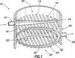
本発明に係る分散/捕集システム10は、図1から4に示すように、容器50内に位置している。図1によると、流体(図示せず。例えば水等)が入口チューブ12を通って分散器40に入り、分散器40の上部ヘッダ14を流れ落ちる。流体は、上部ヘッダ14から、1セットの上部側部16を通って、上部ヘッダ14から離れるように外に向かって流れる。上部側部16は、図3に最もよく示されるように、流体をその長さ方向に沿って分散させ、また、上部側部16から出て、分散器40の下にある媒体層18へと流体を分散させる。流れは媒体層18中を進み、媒体層18の下にある捕集器20により捕集される。媒体層18中を流れた後、流れは捕集器20の1セットの下部側部22に入る。ここから、流れは、下部側部22に沿って、容器50の外側に向かって外方向に進み、下部ヘッダ24内に入る。下部ヘッダ24は2つの分枝25を含み、この分枝25が流れを概ね容器50の周囲に沿って運び、容器50を出る出口管26に運ぶ。
The dispersion /
図2では、分散器を通る流れの方向が一連の矢印28で示されている。示されているように、流れは入口管12から容器50に入り、入口管12から離れるにしたがって細くなっている上部ヘッダ14を下って進む。上部ヘッダ14は上部側部16に流体の伝達をする。したがって、上部ヘッダ14を介して進む流れは上部側部16に分散され、上部側部16が流れを上部ヘッダ14から離れる方向に進める。それぞれの上部側部16は穴のあいたパイプ(図示せず)を含み、このパイプにより、流れが上部側部16から出て、分散器40の下にある媒体層18に入る。上部側部16の穴のあいたパイプは、ワイヤメッシュやV字型の外形のワイヤスクリーン等のろ過材料に囲まれていてもよい。このように、流体は、それぞれの上部側部16により、それぞれの上部側部の長さにわたって分散される。さらに、上部側部16の穿孔をそれぞれの上部側部16の長さに沿ってサイズを変えて行うことで、それぞれの上部側部16の長さに沿った上部側部16の異なる点からでも均一に流れ出るようにしてもよい。換言すると、上部ヘッダ14に対しての(toward)上部側部16の穿孔を、上部ヘッダ14から離れた上部側部16の穿孔よりも大きくあるいは小さくして、そこを通った流れを一様に分散させてもよい。
In FIG. 2, the direction of flow through the disperser is indicated by a series of
流れは、上部側部16を出た後、図3に示すように、媒体層18を通って進む。図3および1に最もよく示されるように、流れが媒体層18を通って進んだ後、捕集器20の下部側部22に接触する。下部側部22は、上部側部16について記載したものとほぼ同じように構成される。好ましくは、下部側部はワイヤメッシュやV字型の外形のワイヤスクリーン等のろ過材料に囲まれた穴のあいたパイプを含んでいる。しかし、通常の技術の1つによって、流れが通ることができるような上部または下部側部の他の構成が用いられてもよいと解釈できるだろう。流れが下部側部22に入ると、図4および1に最もよく示されるように、概ね容器50の周囲に沿って延びている「ウィッシュボーン型の」または「蹄鉄型の」下部ヘッダ24の方へと外に向かう。図4に関して、捕集器20を通る流れの方向は概して矢印30にて示される。図4に示されるように、流れが下部側部22を降りる方向に向かい、下部ヘッダ24に入った後、「ウィッシュボーン型の」下部ヘッダ24の2つの分枝25のうちの1つによって出口管26に運ばれる。ここから、流れが出口管26を通って容器50を出る。上部ヘッダ14と同様に、下部ヘッダ24は、一様な流れの分散を容易にするためにだんだん細くなっており、分散/捕集システム10の全体にわたって圧力低下を生じさせる。
After exiting the
図1に関して、上部側部16の長さに沿った1点において分散器40から出た流れは、流れが上部側部16を出た点のほぼまっすぐ下の点で下部側部22に入る。換言すれば、上部側部16からの各流出点には、まっすぐ下の下部側部22に、対応する、対の流入点がある。このように、本発明の分散/捕集システム10を通る流体粒子の流れがどの経路をとるかにかかわらず、流体粒子が入口管12から出口管26までを移動する距離がほぼ一定となる。換言すれば、流体粒子が上部ヘッダ14を下り、上部ヘッダ14に非常に近い上部側部16を出る流れ経路に従った場合、下部ヘッダ24の分枝25から比較的遠い点にて、対応する下部側部22に入ることになる。このようにして、流体粒子が上部側部16の長さに沿っては比較的短い距離を流動したとしても、比較的長い距離を流動して下部側部22を通って下部ヘッダ24に至って容器から出ることになる。同様に、上部ヘッダ14から比較的遠い点にて上部側部16を出た流体粒子は、下部ヘッダ24に比較的近い距離にて下部側部22へ入ることになる。どちらの場合も、流体粒子が分散/捕集システム10中を移動する距離はほぼ同じになり、粒子が容器50内で費やす時間も同じになる。これは、入口管12から比較的遠くで分散器40を出る流体に対する、入口管12に比較的近くで分散器40を出る流体についても有効であり、その逆についても同じである。入口管12から比較的近くで分散器40を出た流れは、出口管26から比較的遠くで捕集器20に入り、したがって、出口管26に到達するまでに下部ヘッダ24において比較的長い距離を移動する必要がある。入口管12から比較的離れた上部ヘッダ14を出た流体は、出口管26の比較的近くで下部ヘッダ24に入り、容器50を出る前に、下部ヘッダ24において比較的短い距離を移動すればよい。
With respect to Figure 1, the flow exiting the
入口管12は、容器50の周りにおいて出口管26から約180度の方向に向けられていることが好ましく、上部ヘッダ14および下部ヘッダ24の両方がだんだん細くなっていくことが好ましい。分散器40と捕集器20とは、概ね、示されたように配置され、媒体層18を介しての均一な流動分散、システム10での均一な圧力低下を生じさせ、本発明に係る分散/捕集システム10で比較的高い分散効率を得ることが好ましい。上部及び下部側部16、22は長さに対応して穿孔(図示せず)のサイズを変化させることでさらに均一な流動分散と高い分散効率を導く。加えて、システム10は、流路の長さを一定に作ることで、滞留時間(流体がシステム10全体を通って流れるのにかかる時間)を均衡させている。図3に示すように、容器50全体の高さおよび媒体層18の高さを要求されたとおりとすることでも、滞留時間を抑えられる。最後に、本発明に係る分散/捕集システム10は媒体層18を介してプラグフロー(plug flow)を作る。分散/捕集システム10の上記の詳細な記載は、通常の技術のひとつにより与えられることは明白である。
The
このシステムの志向は、媒体層18を通り、捕集器20を通って戻る、分散器40内の経路が、経路の方向にかかわらず、同じ滞留時間を有するというフラクタルシステムの振る舞いに近似できる。一般的な概念は、上部に分散器40として連続的に縮小するまっすぐなヘッダ14と、底部に一様な捕集とバックウォッシングとを行うための蹄鉄型のヘッダ24を使用した点である(配置は逆でもかまわない)。
The orientation of this system can be approximated to the behavior of a fractal system in which the path through the
本発明は、ある好ましい実施の形態を挙げて詳細に説明しているが、先に記載および定義した本発明の範囲内で変更や改良を行ってもかまわない。 While the invention has been described in detail with reference to certain preferred embodiments, modifications and improvements may be made within the scope of the invention as described and defined above.
以上、本発明の実施の形態について説明してきたが、本発明のその他のおよびさらなる実施の形態は、その基本的範囲からそれないような工夫をされてもよい。その範囲は以下の請求項により決定される。 While the embodiments of the present invention have been described above, other and further embodiments of the present invention may be devised not to depart from its basic scope. The scope is determined by the following claims.
Claims (21)
上記入口と流体の伝達をする第1のヘッダと、
上記出口と流体の伝達をする第2のヘッダと、
媒体層と、を含んでなり、
第1のヘッダに流入する流体が上記媒体層を通るように導き、第2のヘッダにより捕集する流体処理システムにおいて、
上記ヘッダのうちの一方のヘッダが2つの分枝を含んでなり、
上記2つの分枝は、概ね上記流体処理システムの周囲を周るように延びた蹄鉄型に形成されていて、
上記第1のヘッダ及び上記第2のヘッダによって、上記媒介層を介しての均一な流動分散を生じさせることを特徴とする流体処理システム。A chamber having an inlet and an outlet;
A first header in fluid communication with the inlet;
A second header in fluid communication with the outlet;
A medium layer, and
In a fluid treatment system in which fluid flowing into a first header is directed through the media layer and collected by a second header,
Ri one header of the upper SL header name contains two branches,
The two branches are formed in a horseshoe shape extending generally around the fluid treatment system,
The fluid treatment system according to claim 1, wherein the first header and the second header cause uniform flow distribution through the intermediate layer .
第1のヘッダにより上記流体を分散させるステップと、
媒体層に上記流体を流すステップと、
2つの分枝を有する第2のヘッダにより上記流体を捕集するステップと、
上記チャンバーの出口から上記流体を送り出すステップと、を含む流体処理方法であって、
上記ヘッダのうちの一方のヘッダが2つの分枝を含んでなり、当該2つの分枝が、上記チャンバーの周囲を周るように延びた蹄鉄型に形成されていることによって、上記媒介層を介しての均一な流動分散を生じさせることを特徴とする流体処理方法。Flowing a fluid to the inlet of the chamber;
Dispersing the fluid by a first header;
Flowing the fluid through the media layer;
Collecting the fluid by means of a second header having two branches;
Delivering the fluid from an outlet of the chamber, comprising: a fluid treatment method comprising :
One of the headers includes two branches, and the two branches are formed in a horseshoe shape extending around the chamber, thereby providing the mediating layer. A fluid processing method characterized by causing uniform flow dispersion through
Applications Claiming Priority (2)
| Application Number | Priority Date | Filing Date | Title |
|---|---|---|---|
| US30661901P | 2001-07-19 | 2001-07-19 | |
| PCT/GB2002/003301 WO2003008064A1 (en) | 2001-07-19 | 2002-07-18 | Distributor/collector system |
Publications (2)
| Publication Number | Publication Date |
|---|---|
| JP2004534644A JP2004534644A (en) | 2004-11-18 |
| JP4354274B2 true JP4354274B2 (en) | 2009-10-28 |
Family
ID=23186098
Family Applications (1)
| Application Number | Title | Priority Date | Filing Date |
|---|---|---|---|
| JP2003513665A Expired - Lifetime JP4354274B2 (en) | 2001-07-19 | 2002-07-18 | Dispersion / collection system |
Country Status (6)
| Country | Link |
|---|---|
| US (1) | US6919020B2 (en) |
| EP (1) | EP1406713B1 (en) |
| JP (1) | JP4354274B2 (en) |
| AU (1) | AU2002354882B2 (en) |
| BR (1) | BR0209299B1 (en) |
| WO (1) | WO2003008064A1 (en) |
Families Citing this family (11)
| Publication number | Priority date | Publication date | Assignee | Title |
|---|---|---|---|---|
| GB2380951C (en) * | 2001-10-18 | 2011-09-28 | Derek Colin Tolley | Filtration of liquid media |
| DE102004043362A1 (en) * | 2004-09-08 | 2006-03-09 | Bayer Technology Services Gmbh | Liquid distributor and liquid collector for chromatography columns |
| US20080121580A1 (en) * | 2006-11-27 | 2008-05-29 | Weatherford/ Lamb, Inc. | Geometrically Variable Filter Underdrain Header |
| FR2930454B1 (en) * | 2008-04-25 | 2010-11-19 | Inst Francais Du Petrole | SYSTEM FOR DISTRIBUTING AND COLLECTING FLUIDS IN A MULTI-PURPOSE COLUMN |
| DE102009009703A1 (en) * | 2009-02-19 | 2010-08-26 | Andrea Claudia Walter | chromatography |
| CN102772916A (en) * | 2012-08-17 | 2012-11-14 | 山东兆光色谱分离技术有限公司 | Distributor for simulated moving bed separation technology |
| TWI531403B (en) * | 2013-03-01 | 2016-05-01 | 格瑞福科技有限責任公司 | Underdrain filter for power generation and liquid process filtration vessels and method of using the same |
| CN107014236B (en) * | 2017-05-27 | 2023-06-23 | 中冶京诚工程技术有限公司 | Uniform water distribution system for pool |
| FR3072885B1 (en) * | 2017-10-27 | 2019-11-15 | IFP Energies Nouvelles | NEW MERIDIAN PANEL DISTRIBUTION SYSTEM FOR SIMUL MOBILE BED SEPARATION METHOD USING SERIES N-COLUMNS |
| CN110251982B (en) * | 2019-07-15 | 2021-07-23 | 万华化学集团股份有限公司 | High-operation-elasticity liquid distribution device and method |
| US11331616B2 (en) * | 2020-09-25 | 2022-05-17 | Mark Henderson | Pool filter assembly |
Family Cites Families (17)
| Publication number | Priority date | Publication date | Assignee | Title |
|---|---|---|---|---|
| CH231904A (en) * | 1943-04-27 | 1944-04-30 | Sa Clensol | Water softener. |
| US3268605A (en) | 1961-11-06 | 1966-08-23 | Universal Oil Prod Co | Supervisory control system for a simulated moving bed separation process |
| US3214247A (en) | 1963-02-25 | 1965-10-26 | Universal Oil Prod Co | Fluid distributing means for packed chambers |
| US3523762A (en) | 1967-05-19 | 1970-08-11 | Universal Oil Prod Co | Baffled chamber for a plurality of contact beds to preclude diffused fluid flow |
| US4099559A (en) * | 1976-05-10 | 1978-07-11 | Olin Corporation | Solar absorber plate design |
| US4407269A (en) * | 1978-07-07 | 1983-10-04 | Sunsearch, Inc. | Solar energy collector system having balanced heat-exchange fluid flow |
| US4378292A (en) | 1981-09-11 | 1983-03-29 | Uop Inc. | Fixed bed multiple zone fluid-solids contacting apparatus |
| US4379050A (en) * | 1981-10-27 | 1983-04-05 | The United States Of America As Represented By The Secretary Of The Army | Granular fluid biofilter reversing |
| US5124133A (en) | 1985-10-31 | 1992-06-23 | Wilmer Schoenrock | Apparatus and method for providing a uniform flow profile through large diameter, low-pressure vessels |
| US4809744A (en) * | 1987-10-08 | 1989-03-07 | James River Corporation | Uniform fluid distribution system |
| US4871463A (en) | 1988-08-23 | 1989-10-03 | Sepratech | Vertical reaction vessel |
| US4999102A (en) | 1988-12-16 | 1991-03-12 | The Amalgamated Sugar Company | Liquid transfer manifold system for maintaining plug flow |
| WO1993002327A1 (en) * | 1991-07-24 | 1993-02-04 | Rheem Australia Limited | Solar collector with freeze damage protection |
| FR2708480B1 (en) | 1993-08-02 | 1996-05-24 | Inst Francais Du Petrole | Single-phase fluid distributor-mixer-extractor for granular solids beds. |
| EP0769316B1 (en) | 1995-10-20 | 2003-01-15 | Institut Français du Pétrole | Distributor for independently injecting and/or collecting fluids |
| FR2755879B1 (en) | 1996-11-19 | 1999-01-08 | Inst Francais Du Petrole | PRESSURE BALANCING AND FLUSHING DEVICE IN AN ENCLOSURE |
| FR2782657B1 (en) | 1998-09-02 | 2000-09-29 | Inst Francais Du Petrole | FLUID DISTRIBUTOR-COLLECTOR SYSTEM AND METHOD |
-
2002
- 2002-07-18 US US10/198,653 patent/US6919020B2/en not_active Expired - Lifetime
- 2002-07-18 JP JP2003513665A patent/JP4354274B2/en not_active Expired - Lifetime
- 2002-07-18 WO PCT/GB2002/003301 patent/WO2003008064A1/en active IP Right Grant
- 2002-07-18 BR BRPI0209299-9A patent/BR0209299B1/en not_active IP Right Cessation
- 2002-07-18 AU AU2002354882A patent/AU2002354882B2/en not_active Expired
- 2002-07-18 EP EP02751316A patent/EP1406713B1/en not_active Expired - Lifetime
Also Published As
| Publication number | Publication date |
|---|---|
| WO2003008064A1 (en) | 2003-01-30 |
| US20030024885A1 (en) | 2003-02-06 |
| US6919020B2 (en) | 2005-07-19 |
| EP1406713A1 (en) | 2004-04-14 |
| JP2004534644A (en) | 2004-11-18 |
| AU2002354882B2 (en) | 2007-08-02 |
| EP1406713B1 (en) | 2007-04-04 |
| BR0209299A (en) | 2004-07-27 |
| BR0209299B1 (en) | 2010-12-14 |
Similar Documents
| Publication | Publication Date | Title |
|---|---|---|
| JP4354274B2 (en) | Dispersion / collection system | |
| US3289756A (en) | Heat exchanger | |
| AU2018229504B2 (en) | Diffuser Basket | |
| JP5319822B2 (en) | Screen intake device flow control and support device | |
| KR101893580B1 (en) | filter assembly | |
| US5037548A (en) | Multiple-disc filter having smaller passageways on the outlet side | |
| JPS63171612A (en) | Impurity separator | |
| AU2002354882A1 (en) | Distributor/collector system | |
| JP2016517349A5 (en) | ||
| US6576146B2 (en) | Filtration element employing improved backwash feature and method of utilizing same | |
| US20090008341A1 (en) | Fluid removing filter apparatus and method of removing fluid from a mixture | |
| JP2521389B2 (en) | In-line type strainer | |
| KR101741775B1 (en) | assembly of RO sheet and RO filter | |
| JPS6369509A (en) | Hollow yarn membrane filter | |
| JP7243964B2 (en) | filter element | |
| JP3180639B2 (en) | Gas separation membrane module | |
| JP2007132343A (en) | Fuel filter | |
| US11827530B2 (en) | Irrigation liquid filtration system | |
| JP2001252508A (en) | Method and apparatus for distributing flow | |
| CN215962764U (en) | Gas filtration system | |
| JPH0753681Y2 (en) | Deaerator | |
| US20110253644A1 (en) | Method and apparatus for filtering fluids | |
| WO1996035495A1 (en) | Vortex air separator for hydronic heating system | |
| JP2001205009A (en) | Laminated filter | |
| JPH06339616A (en) | Membrane separating apparatus |
Legal Events
| Date | Code | Title | Description |
|---|---|---|---|
| A621 | Written request for application examination |
Free format text: JAPANESE INTERMEDIATE CODE: A621 Effective date: 20050607 |
|
| RD02 | Notification of acceptance of power of attorney |
Free format text: JAPANESE INTERMEDIATE CODE: A7422 Effective date: 20050803 |
|
| A977 | Report on retrieval |
Free format text: JAPANESE INTERMEDIATE CODE: A971007 Effective date: 20071115 |
|
| A131 | Notification of reasons for refusal |
Free format text: JAPANESE INTERMEDIATE CODE: A131 Effective date: 20071204 |
|
| A521 | Request for written amendment filed |
Free format text: JAPANESE INTERMEDIATE CODE: A523 Effective date: 20080228 |
|
| TRDD | Decision of grant or rejection written | ||
| A01 | Written decision to grant a patent or to grant a registration (utility model) |
Free format text: JAPANESE INTERMEDIATE CODE: A01 Effective date: 20090707 |
|
| A01 | Written decision to grant a patent or to grant a registration (utility model) |
Free format text: JAPANESE INTERMEDIATE CODE: A01 |
|
| A61 | First payment of annual fees (during grant procedure) |
Free format text: JAPANESE INTERMEDIATE CODE: A61 Effective date: 20090729 |
|
| R150 | Certificate of patent or registration of utility model |
Ref document number: 4354274 Country of ref document: JP Free format text: JAPANESE INTERMEDIATE CODE: R150 Free format text: JAPANESE INTERMEDIATE CODE: R150 |
|
| FPAY | Renewal fee payment (event date is renewal date of database) |
Free format text: PAYMENT UNTIL: 20120807 Year of fee payment: 3 |
|
| FPAY | Renewal fee payment (event date is renewal date of database) |
Free format text: PAYMENT UNTIL: 20130807 Year of fee payment: 4 |
|
| R250 | Receipt of annual fees |
Free format text: JAPANESE INTERMEDIATE CODE: R250 |
|
| R250 | Receipt of annual fees |
Free format text: JAPANESE INTERMEDIATE CODE: R250 |
|
| R250 | Receipt of annual fees |
Free format text: JAPANESE INTERMEDIATE CODE: R250 |
|
| R250 | Receipt of annual fees |
Free format text: JAPANESE INTERMEDIATE CODE: R250 |
|
| R250 | Receipt of annual fees |
Free format text: JAPANESE INTERMEDIATE CODE: R250 |
|
| S111 | Request for change of ownership or part of ownership |
Free format text: JAPANESE INTERMEDIATE CODE: R313113 |
|
| S531 | Written request for registration of change of domicile |
Free format text: JAPANESE INTERMEDIATE CODE: R313531 |
|
| R350 | Written notification of registration of transfer |
Free format text: JAPANESE INTERMEDIATE CODE: R350 |
|
| R250 | Receipt of annual fees |
Free format text: JAPANESE INTERMEDIATE CODE: R250 |
|
| R250 | Receipt of annual fees |
Free format text: JAPANESE INTERMEDIATE CODE: R250 |
|
| R250 | Receipt of annual fees |
Free format text: JAPANESE INTERMEDIATE CODE: R250 |
|
| R250 | Receipt of annual fees |
Free format text: JAPANESE INTERMEDIATE CODE: R250 |
|
| R250 | Receipt of annual fees |
Free format text: JAPANESE INTERMEDIATE CODE: R250 |
|
| EXPY | Cancellation because of completion of term |