JP4354141B2 - Container with lid - Google Patents
Container with lid Download PDFInfo
- Publication number
- JP4354141B2 JP4354141B2 JP2001374914A JP2001374914A JP4354141B2 JP 4354141 B2 JP4354141 B2 JP 4354141B2 JP 2001374914 A JP2001374914 A JP 2001374914A JP 2001374914 A JP2001374914 A JP 2001374914A JP 4354141 B2 JP4354141 B2 JP 4354141B2
- Authority
- JP
- Japan
- Prior art keywords
- lid
- container
- claw
- operation part
- container body
- Prior art date
- Legal status (The legal status is an assumption and is not a legal conclusion. Google has not performed a legal analysis and makes no representation as to the accuracy of the status listed.)
- Expired - Lifetime
Links
Images


Landscapes
- Purses, Travelling Bags, Baskets, Or Suitcases (AREA)
- Containers And Packaging Bodies Having A Special Means To Remove Contents (AREA)
- Closures For Containers (AREA)
Description
【0001】
【発明の属する技術分野】
本発明は、容器本体の天面側に設けられた取出口を開閉可能な上蓋にて閉じるようにした容器に関する。
【0002】
【従来の技術】
多数枚のウエットティッシュを所定枚数ずつ順に取り出せるように折り畳んで収容した袋詰め物品のための樹脂製容器として、例えば特開平11−180460号公報(以下、先行文献1と呼ぶ。)に開示されている蓋付き容器が知られている。この公報の容器は、容器本体の底部をほぼ全面的に開口させ、その開口部を容器本体から分離可能な底蓋にて閉じることにより、袋詰めされたウエットティッシュを交換可能としたものである。容器本体の天面側にはウエットティッシュの取出口が形成され、その取出口は容器本体に対してヒンジ結合された上蓋にて閉じられる。容器本体には上蓋を開く方向に付勢する上蓋付勢手段と、その上蓋付勢手段の力に抗して上蓋を閉じた位置に保持する保持部とが設けられている。ユーザーが保持部を押し込み操作するとその保持部と上蓋との噛み合いが外れ、上蓋が上蓋付勢手段によって開かれる。つまり、上蓋はいわばワンプッシュで開放され、ユーザーにとっては使い勝手がよい。
【0003】
【発明が解決しようとする課題】
ところで、先行文献1に記載の容器の保持部は、例えば図32に示すように容器本体200と一体の操作部201に設けられた爪部202と、上蓋203に設けられた爪部204とを上下方向に噛み合わせて上蓋203を保持している。操作部201の先端をユーザーが押し込むと本体側の爪部202が上蓋203から後退し、それにより上蓋203の拘束が解除されて上蓋203が開放される。
【0004】
しかしながら、上記のような爪部202,204同士の噛み合い構造では、容器に何らかの衝撃が加わると爪部202,204同士の噛み合いが簡単に外れ、上蓋203がばね力で開放される。上蓋が組み込まれた容器本体を一つずつ生産ラインに載せて搬送するときにこうした現象が生じると、容器本体の搬送姿勢が安定せず、搬送不良を招く。
【0005】
また、特開平9−58725号公報(以下、先行文献2と呼ぶ。)には、上蓋の爪部と噛み合う爪部を備えた開放用操作部材を容器本体に対してヒンジ結合し、その操作部材に設けたばね部材により開放用操作部材を爪部同士が噛み合う方向に付勢する容器が開示されている。しかし、その容器の爪部は図32に示すものと同様であり、噛み合いが外れやすいことに変わりはない。しかも、先行文献2の容器は、上蓋の爪部を押し上げるフランジが開放用操作部材に設けられている。従って、容器の落下時の衝撃で操作部材が回転すると上蓋を押し上げる力が発生し、その力が爪部同士の噛み合いを外すように作用するので、上蓋がより一層開き易くなることがある。また、開放用操作部材のばね部が片持ち状態で設けられているため、繰り返し使用に対するばね部の強度に不安がある。
【0006】
特開2000−211661号公報(以下、先行文献3と呼ぶ。)には、上蓋を閉じた状態に保持する爪部を上蓋と容器本体とに設け、かつ、容器本体には開放操作用の操作部材をヒンジを介して取り付けた容器が開示されている。この容器では、操作部材の押し込み操作が上蓋に対して上向きの力として伝達され、それにより上蓋側の爪部が容器本体側の爪部を乗り越えて上蓋の拘束が解除される。操作部材には、これを非操作状態、つまり上蓋を押し上げない状態に保持するためのばね部材が一体に成形されている。しかし、そのばね部材が爪部同士を相互に押し付けることはない。
【0007】
本発明は、内容物の取出口を覆う蓋を容器本体に対して確実に拘束でき、振動等による蓋の意図しない開放を防止できる蓋付き容器を提供することを目的とする。
【0008】
また、本発明は、蓋を開くために操作される操作部品を容器本体に回動自在に取り付ける場合において、その操作部品が爪部を噛み合いを外す方向に不用意に移動して蓋が意図せずに開放されるおそれがない蓋付き容器を提供することをも目的とする。
【0009】
【課題を解決するための手段】
以下、本発明について説明する。なお、本発明の理解を容易にするために添付図面の参照符号を括弧書きにて付記するが、それにより本発明が図示の形態に限定されるものではない。
【0010】
本発明の第1の蓋付き容器は、内容物の取出口(10)を有する容器本体(2)と、前記容器本体にヒンジ部(44)を介して連結され、前記取出口を閉鎖可能な蓋(4)と、前記容器本体と前記蓋との間に配置されて前記蓋を開く方向に付勢する蓋付勢手段(5)とを具備し、前記蓋側及び前記容器本体側にそれぞれ設けられた一対の爪部(43,63)を噛み合わせて当該蓋を閉じる位置に拘束可能とされ、かつ前記容器本体又は前記蓋に設けられた操作部(6)の操作により前記爪部の噛み合いを解除可能とした蓋付き容器(1)において、前記一対の爪部のうち、いずれか一方の爪部(43)は、他方の爪部(63)の対向面(63a)に沿って当該他方の爪部の先端(AP)まで延び、さらにその先端を越えて裏面(63b)側に回り込む形状を有し、前記操作部が前記容器本体に設けられ、前記操作部及び前記蓋に前記爪部がそれぞれ設けられ、前記容器本体には所定のヒンジ部(64)を介して回動自在な操作部品(6)が取り付けられ、その操作部品が前記操作部として機能し、前記爪部が噛み合う方向へ前記操作部品を付勢するばね手段(65)を備え、前記ばね手段は前記操作部品に一体に形成され、前記操作部品には使用者が触れるための操作面(61a)が設けられ、前記ばね手段は、前記操作部品の前記操作面に対する裏面側に設けられ、前記ばね手段は、その両端部(65a)が前記裏面側に接合された弧を描くように形成され、前記容器本体には、前記ばね手段と当接して前記ばね手段の弾性変形の方向を制限する制限手段(33)が設けられていることを特徴とするものである。
【0011】
この発明の第1の蓋付き容器によれば、爪部が二方向に噛み合うことができる。従って、衝撃や振動が容器に加わっても爪部の噛み合いが外れにくくなり、意図しない蓋の開放を防止することができる。
【0012】
爪部は蓋側及び容器本体側にそれぞれ設けられているが、蓋又は容器本体それ自身に爪部が設けられる場合の他に、蓋又は容器本体に装着される他の部品に爪部が設けられてもよい。例えば、容器本体に操作部として機能する別部品を装着し、その別部品に爪部を設けた場合には当該別部品の爪部が容器本体側の爪部に相当する。操作部は蓋側にあってもよい。
【0013】
容器本体には所定のヒンジ部を介して回動自在な操作部品が取り付けられ、その操作部品が操作部として機能するから、ヒンジ部を軸として操作部品を所定角度回転させることにより蓋が開放される。
【0014】
爪部が噛み合う方向へ前記操作部品を付勢するばね手段を備えているため、操作部材を、爪部が外れる方向へ逃げないように付勢し、意図しない蓋の開放をより確実に防止することができる。
【0015】
ばね手段は操作部品に一体に形成されているから、特に操作部品を樹脂成形品とする場合にはばね手段を一体成形することで部品点数を減らしてコストダウンを図ることができる。
【0016】
操作部品には使用者が触れるための操作面が設けられ、ばね手段は、操作部品の操作面に対する裏面側に設けられているから、ばね手段によって操作面を持ち上げる方向に操作部品を付勢することができる。そのばね手段に抗して操作面を押さえ付けることにより蓋が開放される。
【0017】
ばね手段は、その両端部が裏面側に接合された弧を描くように形成されることにより閉じた形状を描くので比較的剛性が高いばねを簡単に実現できる。しかも、片持ち状態のばねと比較して応力集中が生じにくく、ばね手段の寿命も向上する。
【0019】
容器本体には、ばね手段と当接してばね手段の弾性変形の方向を制限する制限手段(33)が設けられているので、ばね手段が強度的に不利な方向に弾性変形することを防止してばね手段の寿命を向上させることができる。特に弧状のばね手段を設ける場合において、前記制限手段は、前記ばね手段がその両端部と中央とを含む平面に沿って変形するように前記方向を制限することが好ましい。
【0020】
本発明の第2の蓋付き容器は、内容物の取出口(10)を有する容器本体(2)と、前記容器本体にヒンジ部(44)を介して連結され、前記取出口を閉鎖可能な蓋(4)と、前記容器本体と前記蓋との間に配置されて前記蓋を開く方向に付勢する蓋付勢手段(5)とを具備し、前記蓋側及び前記容器本体側にそれぞれ設けられた一対の爪部(43,63)を噛み合わせて当該蓋を閉じる位置に拘束可能とされ、かつ前記容器本体又は前記蓋に設けられた操作部(6)の操作により前記爪部の噛み合いを解除可能とした蓋付き容器(1)において、前記一対の爪部のうち、いずれか一方の爪部(43)は、他方の爪部(63)の対向面(63a)に沿って当該他方の爪部の先端(AP)まで延び、さらにその先端を越えて裏面(63b)側に回り込む形状を有し、前記操作部が前記容器本体に設けられ、前記操作部及び前記蓋に前記爪部がそれぞれ設けられ、前記容器本体には所定のヒンジ部(64)を介して回動自在な操作部品(6)が取り付けられ、その操作部品が前記操作部として機能し、前記操作部品は前記容器本体の凹部(30)に装着され、前記爪部が噛み合った状態からその噛み合いが外れる位置まで前記操作部品を操作したときに、当該操作部品の少なくとも一部(例えば図31の61d)が前記凹部の周囲における容器本体の外面よりも突出し、前記爪部の噛み合いが外れる位置を越えて前記操作部品を操作したときに前記操作部品の前記外面からの突出部分が前記容器本体の凹部のエッジ(30d)と接触して前記操作部品の操作が制限されることを特徴とするものである。この蓋付き容器によれば、上述した蓋付き容器と同様の効果を得ることができ、さらに、操作部品が容器本体の外面から突出しているので操作し易い。特に、指を操作面に正しく添えなくても、例えば手の平や手の甲を操作部品の突出部分に添えて操作部品を操作することによっても蓋を開放できる利点がある。また、爪部の噛み合いが外れる位置を越えて操作部品を操作したときに操作部品の外面からの突出部分が容器本体の凹部のエッジと接触して操作部品の操作が制限されるからばね手段の過度の変形を防止することができる。
【0021】
本発明の第3の蓋付き容器は、内容物の取出口(10)を有する容器本体(2)と、前記容器本体にヒンジ部(44)を介して連結され、前記取出口を閉鎖可能な蓋(4)と、前記容器本体と前記蓋との間に配置されて前記蓋を開く方向に付勢する蓋付勢手段(5)とを具備し、前記蓋側及び前記容器本体側にそれぞれ設けられた一対の爪部(43,63)を噛み合わせて当該蓋を閉じる位置に拘束可能とされ、かつ前記容器本体又は前記蓋に設けられた操作部(6)の操作により前記爪部の噛み合いを解除可能とした蓋付き容器(1)において、前記一対の爪部のうち、いずれか一方の爪部(43)は、他方の爪部(63)の対向面(63a)に沿って当該他方の爪部の先端(AP)まで延び、さらにその先端を越えて裏面(63b)側に回り込む形状を有し、前記操作部が前記容器本体に設けられ、前記操作部及び前記蓋に前記爪部がそれぞれ設けられ、前記容器本体には所定のヒンジ部(64)を介して回動自在な操作部品(6)が取り付けられ、その操作部品が前記操作部として機能し、前記操作部品は前記容器本体の凹部(30)に装着され、前記爪部の噛み合いが外れる位置に前記操作部品を操作したときに、当該操作部品の全体が前記凹部の周囲における容器本体の外面よりも内側に収まっていることを特徴とするものである。この蓋付き容器によれば、上述した蓋付き容器と同様の効果を得ることができ、さらに、凹部内に配置された操作部品に触れない限り爪部が外れないので、操作部品に不用意に接触したり、操作部品の周囲の何らかの障害物等が操作部品に接することにより不用意に蓋が開放されるおそれがない。
【0022】
第2の蓋付き容器においては、前記蓋の爪部と前記操作部品の爪部とを前記操作部品の爪部が上となるようにして相互に噛み合わせた状態において、前記操作部品のヒンジ部の軸線(AX)が前記爪部の噛み合い部分(P)よりも下方でかつ前記蓋から横方向に偏位した位置にあることが望ましい。この場合には、ヒンジ部の軸線を中心とした操作部品の運動により、その操作部品の爪部には、蓋側の爪部から上方に抜ける動作が与えられると同時に、その蓋側の爪部の移動軌跡(図30の48)の外側に後退する動作が与えられる。これにより、操作部品と蓋側の爪部とを上記のように噛み合わせた構造であっても、操作部品を回動操作するだけでその噛み合いを容易に外すことができる。
【0024】
本発明の第4の蓋付き容器は、内容物の取出口(10)を有する容器本体(2)と、前記容器本体にヒンジ部(44)を介して連結され、前記取出口を閉鎖可能な蓋(4)と、前記容器本体と前記蓋との間に配置されて前記蓋を開く方向に付勢する蓋付勢手段(5)と、前記容器本体にヒンジ部(64)を介して装着される操作部品(6)とを具備し、前記蓋及び前記操作部品にそれぞれ設けられた一対の爪部(43,63)を噛み合わせて前記蓋を閉じる位置に拘束可能であり、前記操作部品の操作により前記爪部の噛み合いを解除可能とした蓋付き容器(1)において、前記操作部品には使用者が触れるための操作面(61a)が設けられ、その操作面の裏面側には、当該操作部品を前記爪部が噛み合う方向に付勢するばね手段(65)が設けられ、前記ばね手段は、その両端部(65a)が前記裏面側に接合された弧を描くように前記操作部品に一体に形成され、前記容器本体には、前記ばね手段と当接して前記ばね手段の弾性変形の方向を制限する制限手段(33)が設けられていることを特徴とするものである。この蓋付き容器によれば、上述した蓋付き容器と同様の効果を得ることができる。この蓋付き容器においては、前記制限手段は、前記ばね手段がその両端部と中央とを含む平面に沿って変形するように前記方向を制限してもよい。
【0025】
本発明の第5の蓋付き容器は、内容物の取出口(10)を有する容器本体(2)と、前記容器本体にヒンジ部(44)を介して連結され、前記取出口を閉鎖可能な蓋(4)と、前記容器本体と前記蓋との間に配置されて前記蓋を開く方向に付勢する蓋付勢手段(5)と、前記容器本体にヒンジ部(64)を介して装着される操作部品(6)とを具備し、前記蓋及び前記操作部品にそれぞれ設けられた一対の爪部(43,63)を噛み合わせて前記蓋を閉じる位置に拘束可能であり、前記操作部品の操作により前記爪部の噛み合いを解除可能とした蓋付き容器(1)において、前記操作部品には使用者が触れるための操作面(61a)が設けられ、その操作面の裏面側には、当該操作部品を前記爪部が噛み合う方向に付勢するばね手段(65)が設けられ、前記ばね手段は、その両端部(65a)が前記裏面側に接合された弧を描くように前記操作部品に一体に形成され、前記操作部品は前記容器本体の凹部(30)に装着され、前記爪部が噛み合った状態からその噛み合いが外れる位置まで前記操作部品を操作したときに、当該操作部品の少なくとも一部(例えば図31の61d)が前記凹部の周囲における容器本体の外面よりも突出し、前記爪部の噛み合いが外れる位置を越えて前記操作部品を操作したときに前記操作部品の前記外面からの突出部分が前記容器本体の前記凹部のエッジ(30d)と接触して前記操作部品の操作が制限されることを特徴とするものである。この蓋付き容器によれば、上述した蓋付き容器と同様の効果を得ることができる。
【0026】
本発明の第6の蓋付き容器は、内容物の取出口(10)を有する容器本体(2)と、前記容器本体にヒンジ部(44)を介して連結され、前記取出口を閉鎖可能な蓋(4)と、前記容器本体と前記蓋との間に配置されて前記蓋を開く方向に付勢する蓋付勢手段(5)と、前記容器本体にヒンジ部(64)を介して装着される操作部品(6)とを具備し、前記蓋及び前記操作部品にそれぞれ設けられた一対の爪部(43,63)を噛み合わせて前記蓋を閉じる位置に拘束可能であり、前記操作部品の操作により前記爪部の噛み合いを解除可能とした蓋付き容器(1)において、前記操作部品には使用者が触れるための操作面(61a)が設けられ、その操作面の裏面側には、当該操作部品を前記爪部が噛み合う方向に付勢するばね手段(65)が設けられ、前記ばね手段は、その両端部(65a)が前記裏面側に接合された弧を描くように前記操作部品に一体に形成され、前記操作部品は前記容器本体の凹部に装着され、前記爪部の噛み合いが外れる位置に前記操作部品を操作したときに、当該操作部品の全体が前記凹部の周囲における容器本体の外面よりも内側に収まっていることを特徴とするものである。この蓋付き容器によれば、上述した蓋付き容器と同様の効果を得ることができる。
【0030】
【発明の実施の形態】
図1は本発明の一実施形態に係る容器の外観を示す斜視図であり、(a)は上蓋を閉じた状態を、(b)は上蓋を開いた状態をそれぞれ示している。また、図2は平面図、図3は部分破断正面図、図4は右側面図である。まず、これらの図を参照して容器1の概略を説明する。
【0031】
図1に示すように、本実施形態の蓋付き容器1は、容器本体2と、その容器本体2の底面側に配置される底蓋3と、容器本体2の天面側(図1において上面側)に配置される上蓋4とを有している。容器本体2の下端はほぼ全面的に開口し、その開口は底蓋3にて閉じられる。底蓋3を取り外すことにより、容器本体2の内部にはウエットティッシュの梱包物が装着される。
【0032】
図5はその梱包物の断面図である。梱包物100は、シール性を有する袋101の内部に、多数枚のウエットティッシュ102…102を、開口103から所定枚数ずつ(例えば一枚ずつ)連続的に取り出せるように折り畳んで収容した周知のものである。開口103はシール104にて塞がれており、そのシール104は使用時(すなわち、容器1への収容時)に剥がされる。
【0033】
図1(b)から明らかなように、容器本体2の上部には取出口10が形成される。容器1内の梱包物100に収容されたウエットティッシュ102はその取出口10から所定枚数ずつ引き出される。周知のように、取出口10には、ウエットティッシュ102の取り出しに伴って引き上げられる次のウエットティッシュ102の端部を保持するためのフラップ11…11が設けられる。フラップ11の形状は図示のものに限らず、種々変更してよい。梱包物100の開口103に、フラップ11と同等の機能が備えられているときはフラップ11を省略してもよい。
【0034】
上蓋4はその後端部が容器本体2に対してヒンジ結合されることにより、容器本体2に回動自在に取り付けられる。容器本体2と上蓋4との間には、上蓋4を開く位置に付勢する蓋付勢手段としての板ばね5が配置される。また、容器本体2の前側にはプッシュボタン6が取り付けられる。プッシュボタン6は、板ばね5の力に抗して上蓋4を閉じた位置に保持する保持手段、及び上蓋4を開くために操作される解除操作手段として機能する。以上の容器1において、容器本体2、底蓋3、上蓋4及びプッシュボタン6は樹脂成形品であり、板ばね5は好適には天然又は合成ゴムにて構成される。但し、本発明の容器はこれらの材質にて構成されたものに限定されない。例えば、ゴム素材に代えばね鋼等を利用して板ばね5を形成してもよい。蓋付勢手段は板状のものに限らない。
【0035】
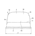
次に、容器1の外観的な特徴について説明する。図1(a)及び図2にハッチングを付して示すように、上蓋4には、閉じたときに容器1の底面(底蓋3によって形成される面)と略平行となる矩形状の平面部7が設けられている。この平面部7は容器1を上下方向に積み重ねたときの安定性を確保するために設けられている。また、平面部7は、各種のラベルを貼り付ける面としても好適に機能する。金型内に予め配置されて樹脂成形品と一体化されるいわゆるインモールドラベルの取付位置としても平面部7は好適である。
【0036】
一方、容器本体2の前後左右には側面12a、12b、12c及び12d(側面12b及び12cは図1において陰に隠れて現れない。)が設けられ、上蓋4の平面部7と容器本体2の前後左右の側面12a〜12dとの間には曲面部8a,8b,8c,8dが配置されている。そして、各曲面部8a,8b,8c,8dは上蓋4及び容器本体2の両者に亘って延びている。換言すれば、曲面部8a〜8dの一部は上蓋4に、残部は容器本体2にそれぞれ振り分けられている。
【0037】
なお、図では、理解の便宜のために曲面部8a〜8dの相互の境界部分、側面12a〜12dの相互の境界部分、及び曲面部8a〜8dと側面12a〜12dとの境界部分のそれぞれに輪郭線を描いているが、実際にはこれらの輪郭部分にも曲面が配置される。また、容器1の安定感を印象付けるため、容器本体2の側面8a〜8dには、容器1の水平断面が上側に向かうほど漸次小さくなるように傾斜又は湾曲が付けられている。容器1の幅W、奥行きD及び高さH(図2〜図4参照)をおよそ170×110×70mmとしたとき、各曲面部8a〜8dの曲率半径は少なくとも30mm以上に設定される。但し、曲率半径が異なる二以上の曲線を接合して曲面部8a〜8dを構成してもよい。また、平面部7の面積は、容器1の底面の面積に対して20%以上確保することが望ましい。なお、平面部7は、容器平面の中央部に設けることが望ましい。平面部7の形状は矩形状に限らず、種々の形状にて設けることができる。
【0038】
容器本体2の下部には、スタックライン13が容器本体2を一周するように設けられている。スタックライン13は、容器本体2の側面12a〜12dを所定量だけ外側にずらすことにより形成されている。図3のVI部を拡大して示した図6(a)から明らかなように、容器本体2の下端内面の四隅には凸部14が形成されている。容器本体2を上下に積み重ねたとき、図6(b)に示すように下側の容器本体2のスタックライン13と上側の容器本体2の凸部14とが当接する。これにより、容器本体2を上下方向に一定の間隔で整然と積み重ねることができる。なお、スタックライン13と凸部14との位置関係は、図7に示すように、容器本体2、上蓋4、板ばね5及びプッシュボタン6を組み合わせたサブアッセンブリ9を上下方向に積み重ねることができるように定められる。
【0039】
容器本体2と底蓋3との連結部分は図6(a)に示すように構成される。すなわち、容器本体2の下端には、先端が拡大したリブ15及びそのリブ15よりも外側に突出するフランジ16がそれぞれ形成されている。底蓋3の外周にはリブ15を受け入れる溝部3aが底蓋3を一周するように形成されている。リブ15を溝部3aに差し込むことにより、溝部3aの外周側の壁部3bがリブ15の拡大部分と噛み合い、それにより底蓋3が容器本体2に対して脱落することなく保持される。
【0040】
次に、容器本体2と上蓋4との関係を説明する。図8は図3のVIII−VIII線に沿った断面図、図9は上蓋4及び板ばね5を省略した容器1の平面図、図10は図3のX部の拡大図である。また、参考のため、上蓋4の詳細を図11〜17に示す。図11は上蓋4の平面図、図12は上蓋4の正面図、図13は上蓋4の背面図、図14は上蓋の右側面図、図15は上蓋4の裏面図、図16は上蓋4の前端部の拡大断面図、図17は上蓋4の後端部の拡大断面図である。
【0041】
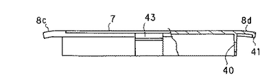
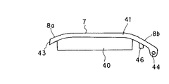
図8及び図9に示すように、容器本体2の天面側には上蓋4の外周と形状を合わせて第1凹部(天面側凹部)21が形成されている。第1凹部21の底板21aは容器1の底面と平行であり、側板21bはその底板21aとほぼ直交する。底板21aには、第1凹部21よりも一段低められた第2凹部22が形成されている。その第2凹部22の底板22aに上述した取出口10及びフラップ11が形成されている。第2凹部22の底板22aも容器1の底面と平行であり、側板22bはその底板22aとほぼ直交する。第2凹部22は全体として楕円状又は長円状に形成されている。図1(b)、及び図15によく示されているように、上蓋4の裏面には第2凹部22と対応した楕円状又は長円状の閉鎖リブ40が形成されている。図8及び図10に示すように、上蓋4を閉じたとき、この閉鎖リブ40が第2凹部22の側板22bの直ぐ内側に入り込む。これにより、取出口10の周囲が閉鎖リブ40及び側板22bにて二重に取り囲まれ、容器1の取出口10の周囲に関して実用上十分な密封性が確保される。
【0042】
図14及び図15に示したように、閉鎖リブ40は上蓋4の平面部7と前後の曲面部8a,8bとに亘って延びている。つまり、閉鎖リブ40によって描かれる閉じた形状は、平面部7及び曲面部8a,8bにまたがって延びている。従って、平面部7と曲面部8a,8bとが閉鎖リブ40によって一体化され、上蓋4に実用上十分な剛性が付与される。また、閉鎖リブ40を平面部7の大きさに影響されることなく拡大し、それによりウエットティッシュ102の噛み込みが発生する頻度を減少させて容器1の使い勝手を向上させることができる。なお、上蓋4の裏面に閉鎖リブ40とは別に補強用のリブを設けてもよい。
【0043】
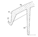
図11及び図15から明らかなように、上蓋4の外周は、上蓋4の前端から左右の後端に向かって緩やかな曲線を描いて延びる湾曲部41と、その湾曲部41の両端を直線状に結ぶ後端部42とを組み合わせて構成されている。湾曲部41は容器本体2の第1凹部21の側板21bと相似形の輪郭を描いて延び、それにより、上蓋4を閉じたときの上蓋4と容器本体2との隙間を必要最小限に抑えて曲面部8a〜8dの一体感を向上させている。そして、湾曲部41の前端には、プッシュボタン6(図1参照)と噛み合う爪部43が設けられている(図16参照)。
【0044】
湾曲部41は容器本体2の背面側の曲面部8bまで延びている。また、湾曲部41の後端(図15において下端)には互いに平行な平行部41a,41aが設けられ、それらの平行部41aにヒンジ軸44,44が設けられている。ヒンジ軸44,44は互いに同軸であり、その軸線は後端部42の延びる方向と平行である。また、図17から明らかなように、後端部42には、上蓋4を閉じた状態でヒンジ軸44の軸芯を越えて下方に延びるストッパフランジ45が設けられている。さらに、上蓋4の裏面には板ばね5を取り付けるための2本の中空状のボス46,46が設けられている。なお、平行部41a,41aの間の幅W2は、上蓋4の最大幅W1に対して85%以上に設定される。
【0045】
一方、図8及び図9から明らかなように、容器本体2の背面側(図8において右端側)には、上蓋4の後端部を受け入れるための第3凹部(背面側凹部)23が形成されている。上蓋4の後端部42が曲面部8bの存在によって、平面部7よりも下方に偏位しているため、第3凹部23の底板23aは第1凹部21の底板21aよりも低い位置にある。第3凹部23の両端には、貫通していない袋状のヒンジ受け穴24,24が形成されている。これらのヒンジ受け穴24に上蓋4のヒンジ軸44を装着することにより、図18に示すように上蓋4が容器本体2に対して開閉自在に取り付けられる。なお、第3凹部23にはストッパ25,25が形成されている(図9参照)。図18(b)に示したように、上蓋4をその平面部7が容器1の底面とほぼ直交する状態まで開くとストッパフランジ45の先端面45aがストッパ25と当接し、それ以上の上蓋4の開放が阻止される。これにより、上蓋4の開閉範囲が適当な範囲に制限される。但し、ストッパ25による開放制限位置は、平面部7が容器1の底面と直交する位置に限定されず、容器1の使用形態に応じて適宜に設定してよい。
【0046】
図9に示すように、第3凹部23の底板23aのほぼ中央には、板ばね5を取り付けるためのばね取付穴26が形成されている。そのばね取付穴26の前方には、第3凹部23を前方に拡大するようにしてばね収容部27が設けられている。ばね収容部27の左右方向の幅は板ばね5の同一方向の幅よりも幾らか大きい。ばね収容部27の前端の側板27aは第2凹部22の側板22bと面一である。図18(a)及び(b)に示すように、板ばね5の一端はばね取付穴26に差し込まれ、他端は上蓋4のボス46に取り付けられる。ボス46には板ばね5を抜け止めするためのキャップ47が取り付けられる。
【0047】
図18(a)に示すように、上蓋4を閉じたとき、板ばね5はその折り返し部5aを容器1の前側に突き出すような姿勢でばね収容部27に収容される。一方、図18(b)に示すように、上蓋4を開いたときには板ばね5がばね収容部27から上方へ引き出されるが、その場合でも板ばね5は容器1の前方に膨らむような弧を描いて湾曲している。従って、上蓋4の開放に伴って後端部42、特にストッパフランジ45が第3凹部23に入り込んでも、上蓋4のストッパフランジ45と板ばね5とが干渉するおそれがない。しかも、ばね取付穴26はストッパ25とほぼ同一位置にあり、ばね取付穴26から引き出された板ばね5がストッパ25に当接したストッパフランジ45の先端面45aよりも容器1の前側に逃げている。これにより、板ばね5と上蓋4の後端部42との干渉がより確実に回避される。
【0048】
なお、図8及び図18に示したように、容器本体2の内面側にはばね取付穴26に対応したボス28が突出させて形成される。このボス28は、上蓋4に曲面部8bを設けたことに伴って第1凹部21よりも深く形成された第3凹部23の底板23aからさらに下方に突出する。このようなボス28が梱包物100の袋101と接触して袋101が破れることがないように、ボス28の両側には略半円状のリブ29,29が設けられている。なお、リブ29の形状は半円状に限定されず、ボス28の先端から基部に向かって末広がりの形状をボス28の周囲に付与するものであればよい。
【0049】
図8に示すように、プッシュボタン6は容器本体2のボタン取付凹部30に装着されている。図21及び図22はそのプッシュボタン6の取付部分を拡大して示す図であり、図21は平面図、図22は断面図である。また、参考のため、容器本体2のボタン取付凹部30の付近の詳細を図23及び図24に、プッシュボタン6の詳細を図25〜29にそれぞれ示す。さらに、プッシュボタン6と上蓋4との噛み合い部分を拡大した様子を図30に示す。
【0050】
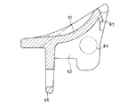
図25〜図29から明らかなように、プッシュボタン6は、天板部61と、その天板部61の周囲に沿って延びる周板部62とを備えている。天板部61の上面はユーザーが指を添えるための操作面61aとして機能する。その操作面61aは中央が凹んだ曲面を描くように形成されている。天板部61の前端側(図25において下側)の外周61bは弧状に湾曲し、後端側の外周61cは上蓋4の湾曲部41に合わせて凹んだ形状に形成されている。天板部61の後端部の中央には、上蓋4の爪部43と噛み合うための爪部63が形成されている。また、周板部62の左右の端部にはヒンジ軸64,64が形成されている。ヒンジ軸64は互いに同軸である。さらに、天板部61の下方にはばね部65が形成されている。ばね部65は弓形であり、その両端65a,65aは周板部62に一体的に接合される。ヒンジ軸64,64の軸線と、ばね部65の弦、すなわち、ばね部65の両端65a,65aを結ぶ線とは互いに平行である。
【0051】
ばね部65の塑性変形を抑えるため、ばね部65の長さは長いほど好ましい。その一方、天板部61の前端側の外周61bは弧状に湾曲しているため、プッシュボタン6の左右方向の幅は前端に向かうほど減少する。そこで、ばね部65の両端65a,65aと周板部62との接合位置は、プッシュボタン6の前端よりも幾らか後退した位置に設定される。なお、プッシュボタン6を射出成形する場合、金型内のばね部65と相補的なキャビティ内にて樹脂の流れが合流すると、その合流した位置に樹脂の接合面が生じ、その部分の強度が低下してばね部65の耐久性に影響を与えるおそれがある。従って、ばね部65を形成する金型においては、注入された樹脂がばね部65を形成するためのキャビティの一方から他方へと流れるように樹脂注入用のゲート位置を定めることが望ましい。
【0052】
一方、図23及び図24に示すように、容器本体2のボタン取付凹部30は、第2凹部22の底板22aよりも低い底板30aと、その底板30aと第1凹部21の底板21aとの間に配置される側板30bと、底板30aと曲面部8aとの間に配置される側板30cとに囲まれている。側板30cはプッシュボタン6の外周61bに沿って湾曲し、その左右の端部にはプッシュボタン6のヒンジ軸64を受け入れるための袋状のヒンジ受け穴31,31が形成されている。また、底板30aには、プッシュボタン6のばね部65を受け入れるためのばね受け溝32が設けられ、その溝32内にはばね部65の中央65b(図26参照)を所定位置に拘束するためのリブ33が設けられている。
【0053】
図21及び図22に示したように、プッシュボタン6はばね部65をばね受け溝32に、ヒンジ軸64をヒンジ受け穴31にそれぞれ嵌め込むことによりボタン取付凹部30内にヒンジ軸64を中心として回動可能に装着される。ばね部65の復元力により、プッシュボタン6はヒンジ軸64を中心として第1凹部21に近付く方向(図22の矢印R1方向)に付勢されている。上蓋4が閉じられると、その上蓋4の爪部43を避けるようにしてプッシュボタン6が図22の矢印R2方向に回転する。そして、爪部43が爪部63を乗り越えると、ばね部65の力でプッシュボタン6が回動し、それにより図22に示したように爪部63,43が相互に噛み合って上蓋4が閉じた状態に保持される。
【0054】
上蓋4が閉じた状態において、ばね部65にて形成される弧を含む平面を仮想したとき、その平面がプッシュボタン6の押し下げ方向とほぼ平行となるようにリブ33はばね部65を拘束する。このため、ばね部65の弾性変形の方向がばね部65によって形成される弧を押し広げる方向に保たれ、不規則な方向への変形によりばね部65が切断する等の不都合が生じるおそれがない。なお、ばね部65の変形方向を所定方向に保持する手段は、リブ33に限定することなく種々変更してよい。例えば、溝32の全体をばね部65とほぼ同一幅に設定し、溝32それ自身によりばね部65の変形方向を制限してもよい。
【0055】
図30に詳しく示したように、爪部43は爪部63の対向面63aに沿って頂点(先端)APまで延び、さらにその頂点APを越えて当該爪部63の裏面63b側に回り込む形状に形成されている。このような噛み合い構造としたため、容器1やそのサブアッセンブリ9を落としたとき等に上蓋4が誤って開くおそれが減少する。つまり、本実施形態の容器1によれば、爪部63,43が上下方向のみならず前後方向にも噛み合っているので、上蓋4が誤って開くおそれが少なく、上蓋の意図しない開放に起因する搬送エラーを防止し、生産効率を向上させることができる。
【0056】
さらに、本実施形態の容器1では、図30に示したように、爪部63,43が互いに噛み合う領域Pに対して、プッシュボタン6の回転中心となるヒンジ軸64の軸芯AXは下方かつ前方に離れている。このように噛み合い領域Pと軸芯AXとの位置関係を設定することにより、プッシュボタン6を押したときに爪部63が爪部43に対して容器1の上方及び前方の両方向に逃げるようになる。従って、爪部63を抱き込むように爪部43を噛み合わせた形状であるにも拘わらず、プッシュボタン6を押し下げるだけの簡単な操作で爪部63,43の噛み合いを確実に外して上蓋4を開放することができる。
【0057】
なお、図22に示したように、プッシュボタン6の前端部6aは容器本体2の外面より突出する。プッシュボタン6を押し下げたときにその前端部6aがボタン取付凹部30のストッパエッジ30dに当接し、それによりプッシュボタン6の押し下げ操作が制限される。このようにプッシュボタン6の操作量を所定範囲に制限したので、ばね部65が過度に撓んで塑性変形を生じるおそれを確実に排除できる。
【0058】
プッシュボタン6の前端部は、プッシュボタン6の操作範囲の全てにおいて容器本体2の外面(ここでは曲面部8a)よりも突出している。従って、操作面61aに指を添えることなく、手の平や甲、あるいはそれ以外の部位をプッシュボタン6に引っ掛けて上蓋4を開放することもできる。このような操作性を重視するならば、例えば図31に示すように、プッシュボタン6の操作面61aに突起部61dを形成し、ユーザーがより容易に指等の部位を引っ掛けられるようにしてもよい。但し、プッシュボタン6の操作範囲の全域でプッシュボタン6の一部が容器1の外面から突出している必要はなく、爪部63,43の噛み合いが外れる位置、つまり図30において爪部43の軌跡線48と爪部63とが接する位置までプッシュボタン6を操作した時点で、そのプッシュボタン6の一部が容器1の外面から突出していればよい。
【0059】
一方、プッシュボタン6が容器1の外面から突出していると、そのプッシュボタン6が不用意に押されたり、その周囲の物体がプッシュボタン6に接触して上蓋4が意図せずに開かれるおそれもある。このような上蓋4の意図せぬ開放を防止するためには、爪部63,43の噛み合いが外れる位置までプッシュボタン6を操作したときに、そのプッシュボタン6の全体が容器1の外面の内側に隠れるように構成するとよい。
【0060】
以上の容器1においては、プッシュボタン6からばね部65を分離し、別のばね部材によってプッシュボタン6を閉じる位置へ付勢してもよい。プッシュボタン6を容器本体2とを一体化し、そのプッシュボタン6の部分と容器本体2とを繋ぐ部分の肉厚を、ヒンジ軸64に相当する位置に回転中心が一致するように調整してもよい。上蓋4のヒンジ軸44は容器1の背面側で容器本体2と結合されてもよいし、天面側で結合されてもよい。板ばね5の個数は2以上であってもよい。ヒンジ軸44とヒンジ受け穴24,ヒンジ軸64とヒンジ受け穴31はそれぞれ軸と穴との関係を反対にしてもよい。
【0061】
なお、上記の実施形態において、天面、底面、側面及び上蓋の語は、取出口を上向きにして容器を設置した場合を基準として各部の位置を相対的に特定したものに過ぎず、実際の使用時の各部の位置はこれらの用語によって限定されるものではない。例えば、本発明の蓋付き容器は、取出口を横向きにした状態で使用されてもよい。
【0062】
【発明の効果】
以上に説明したように、本発明の蓋付き容器によれば、爪部が二方向に噛み合うことができるので、衝撃や振動が容器に加わっても爪部の噛み合いが外れにくくなり、意図しない蓋の開放を防止することができる。また、蓋を開くために操作される操作部品を容器本体に回動自在に取り付ける場合において、その操作部品が爪部を噛み合いを外す方向に不用意に移動して蓋が意図せずに開放されるおそれがない。しかも、ばね手段が閉じた形状を弧を描くので、比較的剛性が高いばねを簡単に実現できる。片持ち状態のばねと比較して応力集中が生じにくく、ばね手段の寿命も向上する。
【図面の簡単な説明】
【図1】本発明の一実施形態に係る容器の外観を示す斜視図であり、(a)は上蓋を閉じた状態を、(b)は上蓋を開いた状態をそれぞれ示す。
【図2】蓋付き容器の平面図。
【図3】蓋付き容器の部分破断正面図。
【図4】蓋付き容器の右側面図。
【図5】蓋付き容器に内蔵されるウエットティッシュの梱包物の断面図。
【図6】容器本体の下端部付近の構成を示す図。
【図7】容器のサブアッセンブリを積み重ねた状態を示す図。
【図8】図3のVIII−VIII線に沿った断面図。
【図9】上蓋と板ばねとを省略した容器の平面図。
【図10】図3のX部の拡大図。
【図11】上蓋の平面図。
【図12】上蓋の正面図。
【図13】上蓋の背面図。
【図14】上蓋の右側面図。
【図15】上蓋の裏面図。
【図16】上蓋の前端側の拡大断面図。
【図17】上蓋の後端側の拡大断面図。
【図18】上蓋と容器本体との連結部分を示す図。
【図19】容器本体の内部に突出するボスの拡大図。
【図20】図19のXX方向からボスをみた状態を示す図。
【図21】プッシュボタンの取付部分を拡大した平面図。
【図22】プッシュボタンの取付部分を拡大した断面図。
【図23】容器本体のボタン取付凹部の平面図。
【図24】ボタン取付凹部の断面図。
【図25】プッシュボタンの平面図。
【図26】プッシュボタンの正面図。
【図27】プッシュボタンの右側面図。
【図28】プッシュボタンの背面図。
【図29】プッシュボタンの断面図。
【図30】上蓋とプッシュボタンとの噛み合い部分を拡大して示す図。
【図31】プッシュボタンの変形例を図21及び図22に対応させて示す図。
【図32】従来の上蓋の拘束部分の構成を示す断面図。
【符号の説明】
1 容器
2 容器本体(特定の構成部品)
3 底蓋
4 上蓋(相手部品)
5 板ばね(蓋付勢手段)
6 プッシュボタン(操作部品)
7 平面部
8a,8b,8c,8d 曲面部
9 サブアッセンブリ
10 取出口
11 フラップ
12a,12b,12c,12d 側面
21 第1凹部(天面側凹部)
21a 底板
21b 側板
22 第2凹部
22a 底板
22b 側板
23 第3凹部(背面側凹部)
23a 底板
24 ヒンジ受け穴
25 ストッパ
26 ばね取付穴(ばね取付部)
27 ばね収容部
28 ボス
29 リブ
30 ボタン取付凹部
30a 底板
30b 側板
30c 側板
30d ストッパエッジ
31 ヒンジ受け穴
32 溝
33 リブ
40 閉鎖リブ
41 湾曲部
41a 平行部
42 後端部
43 爪部
44 ヒンジ軸(ヒンジ部)
45 ストッパフランジ
45a 先端面
46 ボス(ばね取付部)
61 天板部
61a 操作面
61b 前端側の外周
61c 後端側の外周
61d 突起部
62 周板部
63 爪部
64 ヒンジ軸(ヒンジ部)
65 ばね部(ばね手段)
65a ばね部の両端
65b ばね部の中央
100 ウエットティッシュの梱包物
101 袋
102 ウエットティッシュ[0001]
BACKGROUND OF THE INVENTION
The present invention relates to a container in which an outlet provided on the top side of a container body is closed with an openable lid.
[0002]
[Prior art]
As a resin-made container for a bag-packed article in which a large number of wet tissues are folded and stored so that a predetermined number of sheets can be taken out one by one, it is disclosed in, for example, Japanese Patent Application Laid-Open No. 11-180460 (hereinafter referred to as Prior Document 1). Containers with lids are known. In the container of this publication, the bottom of the container main body is opened almost entirely, and the opening is closed with a bottom lid separable from the container main body, so that the wet tissue packed in the bag can be replaced. . A wet tissue outlet is formed on the top side of the container body, and the outlet is closed by an upper lid hinged to the container body. The container body is provided with an upper lid urging means for urging the upper lid in the opening direction and a holding portion for holding the upper lid in a closed position against the force of the upper lid urging means. When the user pushes in the holding portion, the holding portion and the upper lid are disengaged, and the upper lid is opened by the upper lid urging means. In other words, the upper lid is opened with a single push, which is convenient for the user.
[0003]
[Problems to be solved by the invention]
By the way, as shown in FIG. 32, for example, the container holding portion described in the
[0004]
However, in the meshing structure between the
[0005]
Japanese Patent Application Laid-Open No. 9-58725 (hereinafter referred to as Prior Art Document 2) discloses that an opening operating member having a claw portion that meshes with a claw portion of an upper lid is hinge-coupled to a container body, and the operation member The container which urges | biases the operation member for opening | release in the direction which a nail | claw part meshes | engages with the spring member provided in is disclosed. However, the claw portion of the container is the same as that shown in FIG. 32, and the meshing is easily disengaged. And the container of the
[0006]
Japanese Patent Laid-Open No. 2000-211661 (hereinafter referred to as Prior Document 3) provides a claw portion for holding the upper lid in a closed state on the upper lid and the container main body, and the container main body has an opening operation. A container having a member attached via a hinge is disclosed. In this container, the pushing operation of the operating member is transmitted as an upward force to the upper lid, whereby the upper lid side claw portion gets over the container main body side claw portion and the upper lid is released from the restraint. The operating member is integrally formed with a spring member for holding it in a non-operating state, that is, in a state where the upper lid is not pushed up. However, the spring member does not press the claws together.
[0007]
It is an object of the present invention to provide a container with a lid that can reliably restrain a lid that covers a content outlet and prevents the lid from being unintentionally opened due to vibration or the like.
[0008]
In addition, the present invention is intended to allow the lid to be inadvertently moved in the direction of disengaging the claw when the operating component operated to open the lid is rotatably attached to the container body. the object of the invention is to provide a lidded container is no risk of being released without.
[0009]
[Means for Solving the Problems]
The present invention will be described below. In order to facilitate understanding of the present invention, reference numerals in the accompanying drawings are appended in parentheses, but the present invention is not limited to the illustrated embodiment.
[0010]
A container with a first lid of the present invention is connected to a container body (2) having a content outlet (10) and a hinge part (44) to the container body, and the outlet can be closed. A lid (4), and a lid urging means (5) disposed between the container body and the lid to urge the lid in a direction to open the lid, respectively on the lid side and the container body side The pair of claw portions (43, 63) provided can be engaged to restrain the lid to be closed, and the operation of the operation portion (6) provided on the container body or the lid can be used to In the lidded container (1) capable of releasing the engagement, one of the claw portions (43) of the pair of claw portions corresponds to the opposite surface (63a) of the other claw portion (63). It extends to the tip (AP) of the other nail part, and further to the back (63b) side beyond the tip. The operation part is provided in the container body, the claw part is provided in the operation part and the lid, and the container body is rotated via a predetermined hinge part (64). A free operation part (6) is attached, the operation part functions as the operation part, and comprises spring means (65) for urging the operation part in a direction in which the claw part is engaged, and the spring means is the operation part. The operation part is provided with an operation surface (61a) for a user to touch, and the spring means is provided on the back side of the operation part with respect to the operation surface. The both ends (65a) are formed so as to draw an arc joined to the back surface side, and the container body abuts on the spring means to limit the direction of elastic deformation of the spring means. 33) It is characterized in.
[0011]
According to the first lidded container of the present invention, the claw portion can be engaged in two directions. Therefore, even if an impact or vibration is applied to the container, the engagement of the claw portions becomes difficult to be released, and unintentional opening of the lid can be prevented.
[0012]
The claw part is provided on the lid side and the container body side, respectively. In addition to the case where the claw part is provided on the lid or the container body itself, the claw part is provided on other parts attached to the lid or the container body. May be. For example, when a separate part that functions as an operation unit is attached to the container body, and the claw part is provided on the separate part, the claw part of the separate part corresponds to the claw part on the container body side. The operation unit may be on the lid side.
[0013]
The container body rotatable operation unit article is attached via a predetermined hinge portion, since the operation part functions as operation unit, the lid by predetermined angle operation part hinge portion as a shaft Is released.
[0014]
Due to the provision of the spring means to urge the operating direction component claw portion engages the operating member, and biases the escaping in the direction of the claw portion is disengaged, the opening of unintended lid reliably prevented can do.
[0015]
Since it means is formed integrally with the operation part if, it is possible to reduce the cost, especially the operation part reducing the number of parts by integrally molding the spring means in the case of a resin molded article.
[0016]
The operation part provided operation surface for the user touched, place it means, because they provided on the back side for operation surface of the operation part, the operation part in a direction of lifting the operating surface by the spring means Can be energized. The lid is opened by pressing the operating surface against the spring means.
[0017]
Springs means can be easily realized relatively stiff spring so draws a shape that both ends are closed by Rukoto formed in an arc which is joined to the rear surface side. Moreover, stress concentration is less likely to occur compared to the spring of the cantilever, the life of the spring means also you improved.
[0019]
The container body, because the restricting means for restricting the direction of the elastic deformation of the field it means abuts it if it means (33) is provided, the spring means is elastically deformed in strength disadvantageous direction And the life of the spring means can be improved. In particular, when an arcuate spring means is provided, the restricting means preferably restricts the direction so that the spring means is deformed along a plane including both ends and the center thereof.
[0020]
A container with a second lid of the present invention is connected to a container body (2) having a content outlet (10) and a hinge part (44) to the container body, and the outlet can be closed. A lid (4), and a lid urging means (5) disposed between the container body and the lid to urge the lid in a direction to open the lid, respectively on the lid side and the container body side The pair of claw portions (43, 63) provided can be engaged to restrain the lid to be closed, and the operation of the operation portion (6) provided on the container body or the lid can be used to In the lidded container (1) capable of releasing the engagement, one of the claw portions (43) of the pair of claw portions corresponds to the opposite surface (63a) of the other claw portion (63). It extends to the tip (AP) of the other nail part, and further to the back (63b) side beyond the tip. The operation part is provided in the container body, the claw part is provided in the operation part and the lid, and the container body is rotated via a predetermined hinge part (64). A free operation part (6) is attached, the operation part functions as the operation part, the operation part is mounted in the concave part (30) of the container body, and the engagement is released from the state where the claw part is engaged. When the operation component is operated to a position, at least a part of the operation component (for example, 61d in FIG. 31) protrudes from the outer surface of the container main body around the recess and exceeds the position where the engagement of the claw portion is released. When the operation component is operated, a protruding portion of the operation component from the outer surface comes into contact with an edge (30d) of the recess of the container body, and the operation of the operation component is restricted. It is intended. According to this lidded container, the same effect as the above-described lidded container can be obtained, and furthermore, since the operation component protrudes from the outer surface of the container body, it is easy to operate. In particular, there is an advantage that the lid can be opened by operating the operation part without attaching a finger to the operation surface correctly, for example, by attaching the palm or back of the hand to the protruding part of the operation part. Further, when the operating part is operated beyond the position where the engagement of the claw part is disengaged, the protruding part from the outer surface of the operating part comes into contact with the edge of the concave part of the container body, so that the operation of the operating part is restricted. Excessive deformation can be prevented.
[0021]
The third lidded container of the present invention is connected to the container main body (2) having the content outlet (10) and the container main body via a hinge part (44), and the outlet can be closed. A lid (4), and a lid urging means (5) disposed between the container body and the lid to urge the lid in a direction to open the lid, respectively on the lid side and the container body side The pair of claw portions (43, 63) provided can be engaged to restrain the lid to be closed, and the operation of the operation portion (6) provided on the container body or the lid can be used to In the lidded container (1) capable of releasing the engagement, one of the claw portions (43) of the pair of claw portions corresponds to the opposite surface (63a) of the other claw portion (63). It extends to the tip (AP) of the other nail part, and further to the back surface (63b) side beyond the tip. The operation part is provided in the container body, the claw part is provided in the operation part and the lid, and the container body is rotated via a predetermined hinge part (64). A free operation part (6) is attached, the operation part functions as the operation part, the operation part is mounted in the recess (30) of the container body, and the operation part is in a position where the engagement of the claw part is released. When the is operated, the whole of the operation component is located inside the outer surface of the container body around the recess. According to this container with a lid, the same effect as the container with a lid described above can be obtained, and furthermore, the nail part cannot be removed unless the operation part arranged in the recess is touched. There is no risk that the lid will be inadvertently opened due to contact or any obstacle around the operation component coming into contact with the operation component.
[0022]
In the second lidded container, in the state where the claw portion of the lid and the claw portion of the operation component are meshed with each other so that the claw portion of the operation component faces up, the hinge portion of the operation component It is desirable that the axial line (AX) is located below the meshing part (P) of the claw part and is displaced laterally from the lid. In this case, the movement of the operation part centering on the axis of the hinge part causes the claw part of the operation part to move upward from the claw part on the lid side, and at the same time, the claw part on the lid side An operation of retreating outside the movement locus (48 in FIG. 30) is given. Thereby, even if it is the structure which meshed | operated the operation component and the nail | claw part of the lid | cover as mentioned above, the engagement can be easily removed only by rotating operation component.
[0024]
The fourth lidded container of the present invention is connected to the container main body (2) having the content outlet (10) and the container main body via a hinge portion (44), and the outlet can be closed. A lid (4), a lid biasing means (5) disposed between the container main body and the lid for biasing the lid in the opening direction, and attached to the container main body via a hinge portion (64) An operating component (6) that can be constrained to a position where the lid is closed by engaging a pair of claw portions (43, 63) respectively provided on the lid and the operating component. In the lidded container (1) capable of releasing the engagement of the claw portion by the operation of (1), the operation part is provided with an operation surface (61a) for the user to touch, and on the back side of the operation surface, Spring means (65) for urging the operation component in a direction in which the claw portion engages The spring means is formed integrally with the operating component so as to draw an arc in which both end portions (65a) are joined to the back surface side, and the container body abuts on the spring means and Limiting means (33) for limiting the direction of elastic deformation of the spring means is provided. According to this lidded container, the same effect as the above-described lidded container can be obtained. In this lidded container, the restricting means may restrict the direction so that the spring means is deformed along a plane including both ends and the center thereof.
[0025]
The fifth lidded container of the present invention is connected to the container main body (2) having a content outlet (10) and the container main body via a hinge portion (44), and the outlet can be closed. A lid (4), a lid biasing means (5) disposed between the container main body and the lid for biasing the lid in the opening direction, and attached to the container main body via a hinge portion (64) An operating component (6) that can be constrained to a position where the lid is closed by engaging a pair of claw portions (43, 63) respectively provided on the lid and the operating component. In the lidded container (1) capable of releasing the engagement of the claw portion by the operation of (1), the operation part is provided with an operation surface (61a) for the user to touch, and on the back side of the operation surface, Spring means (65) for urging the operation component in a direction in which the claw portion engages Provided, said spring means, both end portions (65a) is formed integrally with the operating part in an arc which is joined to the rear surface side, the operation part is mounted in the recess (30) of the container body When the operation part is operated from the state where the claw part is engaged to the position where the engagement is disengaged, at least a part of the operation part (for example, 61d in FIG. 31) is from the outer surface of the container body around the recess. also protrudes the protruding portion from the outer surface of the operating part when operating the operation part beyond the position where the engagement is disengaged before Symbol claw in contact with the edge of the recess of the container body (30d) The operation of the operation component is limited. According to this lidded container, the same effect as the above-described lidded container can be obtained.
[0026]
The sixth lidded container of the present invention is connected to the container main body (2) having the content outlet (10) and the container main body via a hinge portion (44), and the outlet can be closed. A lid (4), a lid biasing means (5) disposed between the container main body and the lid for biasing the lid in the opening direction, and attached to the container main body via a hinge portion (64) An operating component (6) that can be constrained to a position where the lid is closed by engaging a pair of claw portions (43, 63) respectively provided on the lid and the operating component. In the lidded container (1) capable of releasing the engagement of the claw portion by the operation of (1), the operation part is provided with an operation surface (61a) for the user to touch, and on the back side of the operation surface, Spring means (65) for urging the operation component in a direction in which the claw portion engages The spring means is formed integrally with the operation part so that both ends (65a) of the both ends (65a) draw an arc joined to the back surface side, and the operation part is mounted in a recess of the container body, When the operation component is operated at a position where the claw portion is disengaged, the entire operation component is accommodated inside the outer surface of the container body around the recess. According to this lidded container, the same effect as the above-described lidded container can be obtained.
[0030]
DETAILED DESCRIPTION OF THE INVENTION
1A and 1B are perspective views showing the appearance of a container according to an embodiment of the present invention. FIG. 1A shows a state in which the upper lid is closed, and FIG. 1B shows a state in which the upper lid is opened. 2 is a plan view, FIG. 3 is a partially broken front view, and FIG. 4 is a right side view. First, the outline of the
[0031]
As shown in FIG. 1, a
[0032]
FIG. 5 is a cross-sectional view of the package. The
[0033]
As is clear from FIG. 1 (b), an
[0034]
The
[0035]
Next, external features of the
[0036]
On the other hand,
[0037]
In the figure, for convenience of understanding, the boundary portions of the
[0038]
A
[0039]
The connecting portion between the
[0040]
Next, the relationship between the
[0041]
As shown in FIGS. 8 and 9, a first concave portion (top surface-side concave portion) 21 is formed on the top surface side of the
[0042]
As shown in FIGS. 14 and 15, the closing
[0043]
As apparent from FIGS. 11 and 15, the outer periphery of the
[0044]
The
[0045]
On the other hand, as is apparent from FIGS. 8 and 9, a third recess (back recess) 23 for receiving the rear end of the
[0046]
As shown in FIG. 9, a
[0047]
As shown in FIG. 18A, when the
[0048]
As shown in FIGS. 8 and 18, a
[0049]
As shown in FIG. 8, the
[0050]
As is clear from FIGS. 25 to 29, the
[0051]
In order to suppress plastic deformation of the
[0052]
On the other hand, as shown in FIGS. 23 and 24, the
[0053]
As shown in FIGS. 21 and 22, the
[0054]
In a state where the
[0055]
As shown in detail in FIG. 30, the
[0056]
Furthermore, in the
[0057]
22, the front end 6a of the
[0058]
The front end portion of the
[0059]
On the other hand, if the
[0060]
In the
[0061]
In the above embodiment, the terms top, bottom, side and top lid are merely relative to the position of each part relative to the case where the container is installed with the outlet facing upward, The position of each part at the time of use is not limited by these terms. For example, the container with a lid of the present invention may be used in a state in which the outlet is turned sideways.
[0062]
【The invention's effect】
As described above, according to the container with a lid of the present invention, since the claw portion can be engaged in two directions, the claw portion is not easily disengaged even if an impact or vibration is applied to the container, and the lid is not intended. Can be prevented. In addition , when an operation part that is operated to open the lid is rotatably attached to the container body, the operation part inadvertently moves in a direction to disengage the claw portion, and the lid is unintentionally opened. There is no fear. In addition, since the arc of the closed shape of the spring means is drawn, a spring having relatively high rigidity can be easily realized. Compared with a cantilever spring, stress concentration is less likely to occur and the life of the spring means is improved .
[Brief description of the drawings]
1A and 1B are perspective views showing the appearance of a container according to an embodiment of the present invention, in which FIG. 1A shows a state where an upper lid is closed, and FIG. 1B shows a state where an upper lid is opened.
FIG. 2 is a plan view of a container with a lid.
FIG. 3 is a partially cutaway front view of a container with a lid.
FIG. 4 is a right side view of a container with a lid.
FIG. 5 is a cross-sectional view of a wet tissue package contained in a lidded container.
FIG. 6 is a diagram showing a configuration near the lower end of the container body.
FIG. 7 is a view showing a state where the sub-assemblies of the container are stacked.
8 is a cross-sectional view taken along line VIII-VIII in FIG.
FIG. 9 is a plan view of a container in which an upper lid and a leaf spring are omitted.
10 is an enlarged view of a portion X in FIG. 3;
FIG. 11 is a plan view of the upper lid.
FIG. 12 is a front view of the upper lid.
FIG. 13 is a rear view of the upper lid.
FIG. 14 is a right side view of the upper lid.
FIG. 15 is a rear view of the upper lid.
FIG. 16 is an enlarged cross-sectional view of the front end side of the upper lid.
FIG. 17 is an enlarged cross-sectional view of the rear end side of the upper lid.
FIG. 18 is a view showing a connecting portion between the upper lid and the container main body.
FIG. 19 is an enlarged view of a boss protruding inside the container body.
20 is a view showing a state in which a boss is viewed from the XX direction of FIG. 19;
FIG. 21 is an enlarged plan view of a push button mounting portion.
FIG. 22 is an enlarged cross-sectional view of a push button mounting portion.
FIG. 23 is a plan view of a button mounting recess of the container body.
FIG. 24 is a cross-sectional view of a button mounting recess.
FIG. 25 is a plan view of a push button.
FIG. 26 is a front view of a push button.
FIG. 27 is a right side view of the push button.
FIG. 28 is a rear view of the push button.
FIG. 29 is a cross-sectional view of a push button.
FIG. 30 is an enlarged view showing a meshing portion between an upper lid and a push button.
FIG. 31 is a diagram showing a modification of the push button corresponding to FIGS. 21 and 22;
FIG. 32 is a cross-sectional view showing a configuration of a conventional restraint portion of the upper lid.
[Explanation of symbols]
1
3
5 leaf spring (lid biasing means)
6 Push buttons (operation parts)
7
27
45 Stopper flange 45a Tip face 46 Boss (spring mounting part)
61 Top plate portion
65 Spring part (spring means)
65a Both ends 65b of the spring part 100b of the
Claims (9)
前記一対の爪部のうち、いずれか一方の爪部は、他方の爪部の対向面に沿って当該他方の爪部の先端まで延び、さらにその先端を越えて裏面側に回り込む形状を有し、
前記操作部が前記容器本体に設けられ、前記操作部及び前記蓋に前記爪部がそれぞれ設けられ、
前記容器本体には所定のヒンジ部を介して回動自在な操作部品が取り付けられ、その操作部品が前記操作部として機能し、
前記爪部が噛み合う方向へ前記操作部品を付勢するばね手段を備え、
前記ばね手段が前記操作部品に一体に形成され、
前記操作部品には使用者が触れるための操作面が設けられ、前記ばね手段は、前記操作部品の前記操作面に対する裏面側に設けられ、
前記ばね手段は、その両端部が前記裏面側に接合された弧を描くように形成され、
前記容器本体には、前記ばね手段と当接して前記ばね手段の弾性変形の方向を制限する制限手段が設けられていることを特徴とする蓋付き容器。A container main body having a content outlet, a lid connected to the container main body via a hinge portion, and capable of closing the outlet, and disposed between the container main body and the lid to open the lid A lid urging means for urging in the direction, and a pair of claw portions provided on the lid side and the container main body side are meshed with each other so as to be restrained at a position where the lid is closed, and the container main body Or in a container with a lid that can release the engagement of the claw part by operating the operation part provided in the lid,
Of the pair of claws, one of the claws has a shape that extends to the tip of the other claw along the opposing surface of the other claw, and further wraps around the back to the back side. ,
The operation part is provided in the container body, the claw part is provided in the operation part and the lid,
A rotatable operation part is attached to the container body via a predetermined hinge part, and the operation part functions as the operation part,
Spring means for urging the operating component in a direction in which the claw portion meshes;
The spring means is formed integrally with the operating component;
The operation part is provided with an operation surface for a user to touch, and the spring means is provided on the back side of the operation part with respect to the operation surface,
The spring means is formed so as to draw an arc whose both ends are joined to the back surface side,
A container with a lid, wherein the container main body is provided with a restricting means for contacting the spring means to restrict the direction of elastic deformation of the spring means.
前記一対の爪部のうち、いずれか一方の爪部は、他方の爪部の対向面に沿って当該他方の爪部の先端まで延び、さらにその先端を越えて裏面側に回り込む形状を有し、
前記操作部が前記容器本体に設けられ、前記操作部及び前記蓋に前記爪部がそれぞれ設けられ、
前記容器本体には所定のヒンジ部を介して回動自在な操作部品が取り付けられ、その操作部品が前記操作部として機能し、
前記操作部品は前記容器本体の凹部に装着され、前記爪部が噛み合った状態からその噛み合いが外れる位置まで前記操作部品を操作したときに、当該操作部品の少なくとも一部が前記凹部の周囲における容器本体の外面よりも突出し、
前記爪部の噛み合いが外れる位置を越えて前記操作部品を操作したときに前記操作部品の前記外面からの突出部分が前記容器本体の凹部のエッジと接触して前記操作部品の操作が制限されることを特徴とする蓋付き容器。A container main body having a content outlet, a lid connected to the container main body via a hinge portion, and capable of closing the outlet, and disposed between the container main body and the lid to open the lid A lid urging means for urging in the direction, and a pair of claw portions provided on the lid side and the container main body side are meshed with each other so as to be restrained at a position where the lid is closed, and the container main body Or in a container with a lid that can release the engagement of the claw part by operating the operation part provided in the lid,
Of the pair of claws, one of the claws has a shape that extends to the tip of the other claw along the opposing surface of the other claw, and further wraps around the back to the back side. ,
The operation part is provided in the container body, the claw part is provided in the operation part and the lid,
A rotatable operation part is attached to the container body via a predetermined hinge part, and the operation part functions as the operation part,
The operation component is mounted in a recess of the container body, and when the operation component is operated from a state where the claw portion is engaged to a position where the engagement is disengaged, at least a part of the operation component is a container around the recess. Protrudes from the outer surface of the body,
When the operation component is operated beyond the position where the engagement of the claw portion is disengaged, the protruding portion of the operation component from the outer surface comes into contact with the edge of the concave portion of the container body, and the operation of the operation component is restricted. A container with a lid.
前記一対の爪部のうち、いずれか一方の爪部は、他方の爪部の対向面に沿って当該他方の爪部の先端まで延び、さらにその先端を越えて裏面側に回り込む形状を有し、
前記操作部が前記容器本体に設けられ、前記操作部及び前記蓋に前記爪部がそれぞれ設けられ、
前記容器本体には所定のヒンジ部を介して回動自在な操作部品が取り付けられ、その操作部品が前記操作部として機能し、
前記操作部品は前記容器本体の凹部に装着され、前記爪部の噛み合いが外れる位置に前記操作部品を操作したときに、当該操作部品の全体が前記凹部の周囲における容器本体の外面よりも内側に収まっていることを特徴とする蓋付き容器。A container main body having a content outlet, a lid connected to the container main body via a hinge portion, and capable of closing the outlet, and disposed between the container main body and the lid to open the lid A lid urging means for urging in the direction, and a pair of claw portions provided on the lid side and the container main body side are meshed with each other so as to be restrained at a position where the lid is closed, and the container main body Or in a container with a lid that can release the engagement of the claw part by operating the operation part provided in the lid,
Of the pair of claws, one of the claws has a shape that extends to the tip of the other claw along the opposing surface of the other claw, and further wraps around the back to the back side. ,
The operation part is provided in the container body, the claw part is provided in the operation part and the lid,
A rotatable operation part is attached to the container body via a predetermined hinge part, and the operation part functions as the operation part,
The operation component is mounted in a recess of the container body, and when the operation component is operated at a position where the engagement of the claw portion is disengaged, the entire operation component is inside the outer surface of the container body around the recess. A container with a lid characterized by being accommodated.
前記容器本体にヒンジ部を介して連結され、前記取出口を閉鎖可能な蓋と、
前記容器本体と前記蓋との間に配置されて前記蓋を開く方向に付勢する蓋付勢手段と、
前記容器本体にヒンジ部を介して装着される操作部品とを具備し、
前記蓋及び前記操作部品にそれぞれ設けられた一対の爪部を噛み合わせて前記蓋を閉じる位置に拘束可能であり、
前記操作部品の操作により前記爪部の噛み合いを解除可能とした蓋付き容器において、
前記操作部品には使用者が触れるための操作面が設けられ、その操作面の裏面側には、当該操作部品を前記爪部が噛み合う方向に付勢するばね手段が設けられ、
前記ばね手段は、その両端部が前記裏面側に接合された弧を描くように前記操作部品に一体に形成され、
前記容器本体には、前記ばね手段と当接して前記ばね手段の弾性変形の方向を制限する制限手段が設けられていることを特徴とする蓋付き容器。A container body having a content outlet;
A lid that is connected to the container body via a hinge portion and can close the outlet;
A lid urging means arranged between the container body and the lid to urge the lid in a direction to open the lid;
Comprising an operation part mounted on the container body via a hinge part;
A pair of claw portions respectively provided on the lid and the operation component can be engaged to restrain the lid to be closed.
In the lidded container that can release the engagement of the claw part by operating the operation part,
The operation part is provided with an operation surface for the user to touch, and on the back side of the operation surface, spring means for urging the operation part in a direction in which the claw portion is engaged is provided,
The spring means is formed integrally with the operation component so as to draw an arc whose both ends are joined to the back side,
A container with a lid, wherein the container main body is provided with a restricting means for contacting the spring means to restrict the direction of elastic deformation of the spring means.
前記容器本体にヒンジ部を介して連結され、前記取出口を閉鎖可能な蓋と、
前記容器本体と前記蓋との間に配置されて前記蓋を開く方向に付勢する蓋付勢手段と、
前記容器本体にヒンジ部を介して装着される操作部品とを具備し、
前記蓋及び前記操作部品にそれぞれ設けられた一対の爪部を噛み合わせて前記蓋を閉じる位置に拘束可能であり、
前記操作部品の操作により前記爪部の噛み合いを解除可能とした蓋付き容器において、
前記操作部品には使用者が触れるための操作面が設けられ、その操作面の裏面側には、当該操作部品を前記爪部が噛み合う方向に付勢するばね手段が設けられ、
前記ばね手段は、その両端部が前記裏面側に接合された弧を描くように前記操作部品に一体に形成され、
前記操作部品は前記容器本体の凹部に装着され、前記爪部が噛み合った状態からその噛み合いが外れる位置まで前記操作部品を操作したときに、当該操作部品の少なくとも一部が前記凹部の周囲における容器本体の外面よりも突出し、
前記爪部の噛み合いが外れる位置を越えて前記操作部品を操作したときに前記操作部品の前記外面からの突出部分が前記容器本体の前記凹部のエッジと接触して前記操作部品の操作が制限されることを特徴とする蓋付き容器。A container body having a content outlet;
A lid that is connected to the container body via a hinge portion and can close the outlet;
A lid urging means arranged between the container body and the lid to urge the lid in a direction to open the lid;
Comprising an operation part mounted on the container body via a hinge part;
A pair of claw portions respectively provided on the lid and the operation component can be engaged to restrain the lid to be closed.
In the lidded container that can release the engagement of the claw part by operating the operation part,
The operation part is provided with an operation surface for the user to touch, and on the back side of the operation surface, spring means for urging the operation part in a direction in which the claw portion is engaged is provided,
The spring means is formed integrally with the operation component so as to draw an arc whose both ends are joined to the back side,
The operation component is mounted in a recess of the container body, and when the operation component is operated from a state where the claw portion is engaged to a position where the engagement is disengaged, at least a part of the operation component is a container around the recess. Protrudes from the outer surface of the body,
The protruding portion from the outer surface of the operation part of the operation part in contact with the edge of the recess of the container main body operation is limited when operating the operation part beyond the position where the engagement is disengaged the pawl portion A container with a lid.
前記容器本体にヒンジ部を介して連結され、前記取出口を閉鎖可能な蓋と、
前記容器本体と前記蓋との間に配置されて前記蓋を開く方向に付勢する蓋付勢手段と、
前記容器本体にヒンジ部を介して装着される操作部品とを具備し、
前記蓋及び前記操作部品にそれぞれ設けられた一対の爪部を噛み合わせて前記蓋を閉じる位置に拘束可能であり、
前記操作部品の操作により前記爪部の噛み合いを解除可能とした蓋付き容器において、
前記操作部品には使用者が触れるための操作面が設けられ、その操作面の裏面側には、当該操作部品を前記爪部が噛み合う方向に付勢するばね手段が設けられ、
前記ばね手段は、その両端部が前記裏面側に接合された弧を描くように前記操作部品に一体に形成され、
前記操作部品は前記容器本体の凹部に装着され、前記爪部の噛み合いが外れる位置に前記操作部品を操作したときに、当該操作部品の全体が前記凹部の周囲における容器本体の外面よりも内側に収まっていることを特徴とする蓋付き容器。A container body having a content outlet;
A lid that is connected to the container body via a hinge portion and can close the outlet;
A lid urging means arranged between the container body and the lid to urge the lid in a direction to open the lid;
Comprising an operation part mounted on the container body via a hinge part;
A pair of claw portions respectively provided on the lid and the operation component can be engaged to restrain the lid to be closed.
In the lidded container that can release the engagement of the claw part by operating the operation part,
The operation part is provided with an operation surface for the user to touch, and on the back side of the operation surface, spring means for urging the operation part in a direction in which the claw portion is engaged is provided,
The spring means is formed integrally with the operation component so as to draw an arc whose both ends are joined to the back side,
The operation component is mounted in a recess of the container body, and when the operation component is operated at a position where the engagement of the claw portion is disengaged, the entire operation component is inside the outer surface of the container body around the recess. A container with a lid characterized by being accommodated.
Priority Applications (1)
| Application Number | Priority Date | Filing Date | Title |
|---|---|---|---|
| JP2001374914A JP4354141B2 (en) | 2001-12-07 | 2001-12-07 | Container with lid |
Applications Claiming Priority (1)
| Application Number | Priority Date | Filing Date | Title |
|---|---|---|---|
| JP2001374914A JP4354141B2 (en) | 2001-12-07 | 2001-12-07 | Container with lid |
Related Child Applications (1)
| Application Number | Title | Priority Date | Filing Date |
|---|---|---|---|
| JP2008311188A Division JP5078096B2 (en) | 2008-12-05 | 2008-12-05 | Container with lid |
Publications (2)
| Publication Number | Publication Date |
|---|---|
| JP2003170950A JP2003170950A (en) | 2003-06-17 |
| JP4354141B2 true JP4354141B2 (en) | 2009-10-28 |
Family
ID=19183388
Family Applications (1)
| Application Number | Title | Priority Date | Filing Date |
|---|---|---|---|
| JP2001374914A Expired - Lifetime JP4354141B2 (en) | 2001-12-07 | 2001-12-07 | Container with lid |
Country Status (1)
| Country | Link |
|---|---|
| JP (1) | JP4354141B2 (en) |
Families Citing this family (14)
| Publication number | Priority date | Publication date | Assignee | Title |
|---|---|---|---|---|
| JP4776198B2 (en) * | 2004-09-27 | 2011-09-21 | ユニ・チャーム株式会社 | Wet tissue packaging |
| JP4747556B2 (en) * | 2004-10-25 | 2011-08-17 | 大日本印刷株式会社 | Lid and manufacturing method thereof |
| JP4630710B2 (en) * | 2005-04-01 | 2011-02-09 | ユニ・チャーム株式会社 | Wet material storage container and wet tissue package |
| JP5258522B2 (en) * | 2008-11-14 | 2013-08-07 | ユニ・チャーム株式会社 | Wet tissue package storage container |
| JP5349915B2 (en) | 2008-11-14 | 2013-11-20 | ユニ・チャーム株式会社 | Openable / closable container |
| US20100122985A1 (en) * | 2008-11-14 | 2010-05-20 | Peters Timothy J | Dispenser for Personal Care Products With a Wide Lid-Activation Button |
| JP5349916B2 (en) | 2008-11-14 | 2013-11-20 | ユニ・チャーム株式会社 | Openable / closable container |
| JP5512116B2 (en) | 2008-11-14 | 2014-06-04 | ユニ・チャーム株式会社 | Openable / closable container |
| US8844745B2 (en) | 2010-08-30 | 2014-09-30 | Kimberly-Clark Worldwide, Inc. | Dispenser with a wide lid-activation button having a stabilizing rib |
| JP6089559B2 (en) * | 2012-10-10 | 2017-03-08 | 凸版印刷株式会社 | Container with push button |
| US10793324B2 (en) | 2016-11-11 | 2020-10-06 | The Procter & Gamble Company | Container systems |
| US10577156B2 (en) | 2016-11-11 | 2020-03-03 | The Procter & Gamble Company | Container systems |
| US10501239B2 (en) | 2016-11-11 | 2019-12-10 | The Procter & Gamble Company | Container systems |
| JP2019199290A (en) * | 2018-05-18 | 2019-11-21 | 戎屋化学工業株式会社 | Container with lid |
-
2001
- 2001-12-07 JP JP2001374914A patent/JP4354141B2/en not_active Expired - Lifetime
Also Published As
| Publication number | Publication date |
|---|---|
| JP2003170950A (en) | 2003-06-17 |
Similar Documents
| Publication | Publication Date | Title |
|---|---|---|
| JP4354141B2 (en) | Container with lid | |
| EP1138608B1 (en) | Openable container | |
| CA2274659C (en) | Freely openable container | |
| US5050623A (en) | Vanity case | |
| WO2004063041A1 (en) | Covered container | |
| JP2005289426A (en) | Self-opening type cap mechanism | |
| WO2019171931A1 (en) | Container for housing household tissue paper | |
| US20040251148A1 (en) | Container for cigarette and cigarillo packs | |
| EP3831743A1 (en) | Household thin paper sheet storing container | |
| JP4536881B2 (en) | Packaging paper box with lid | |
| JP4338342B2 (en) | Container with lid | |
| JP5078096B2 (en) | Container with lid | |
| JP3871409B2 (en) | Sealed container | |
| WO2021001643A1 (en) | Latchable package | |
| JP4038235B2 (en) | container | |
| JP3502631B1 (en) | Carton for powder | |
| JPH09140441A (en) | Cosmetic container | |
| JPH0610887Y2 (en) | Compact container | |
| JP4500381B2 (en) | Openable / closable container | |
| JP4549910B2 (en) | Packaging container | |
| JP2023018288A (en) | Sanitary tissue paper storage box | |
| US20220097949A1 (en) | Household-use tissue storage container | |
| JPH0513286Y2 (en) | ||
| JPH0515845Y2 (en) | ||
| JP2001097421A (en) | Single motion operable container |
Legal Events
| Date | Code | Title | Description |
|---|---|---|---|
| A621 | Written request for application examination |
Free format text: JAPANESE INTERMEDIATE CODE: A621 Effective date: 20041006 |
|
| A131 | Notification of reasons for refusal |
Free format text: JAPANESE INTERMEDIATE CODE: A131 Effective date: 20080205 |
|
| A521 | Written amendment |
Free format text: JAPANESE INTERMEDIATE CODE: A523 Effective date: 20080407 |
|
| A131 | Notification of reasons for refusal |
Free format text: JAPANESE INTERMEDIATE CODE: A131 Effective date: 20081007 |
|
| A521 | Written amendment |
Free format text: JAPANESE INTERMEDIATE CODE: A523 Effective date: 20081205 |
|
| TRDD | Decision of grant or rejection written | ||
| A01 | Written decision to grant a patent or to grant a registration (utility model) |
Free format text: JAPANESE INTERMEDIATE CODE: A01 Effective date: 20090630 |
|
| A01 | Written decision to grant a patent or to grant a registration (utility model) |
Free format text: JAPANESE INTERMEDIATE CODE: A01 |
|
| A61 | First payment of annual fees (during grant procedure) |
Free format text: JAPANESE INTERMEDIATE CODE: A61 Effective date: 20090729 |
|
| R150 | Certificate of patent or registration of utility model |
Ref document number: 4354141 Country of ref document: JP Free format text: JAPANESE INTERMEDIATE CODE: R150 Free format text: JAPANESE INTERMEDIATE CODE: R150 |
|
| FPAY | Renewal fee payment (event date is renewal date of database) |
Free format text: PAYMENT UNTIL: 20120807 Year of fee payment: 3 |
|
| FPAY | Renewal fee payment (event date is renewal date of database) |
Free format text: PAYMENT UNTIL: 20120807 Year of fee payment: 3 |
|
| FPAY | Renewal fee payment (event date is renewal date of database) |
Free format text: PAYMENT UNTIL: 20130807 Year of fee payment: 4 |
|
| R250 | Receipt of annual fees |
Free format text: JAPANESE INTERMEDIATE CODE: R250 |
|
| FPAY | Renewal fee payment (event date is renewal date of database) |
Free format text: PAYMENT UNTIL: 20130807 Year of fee payment: 4 |
|
| RD04 | Notification of resignation of power of attorney |
Free format text: JAPANESE INTERMEDIATE CODE: R3D04 |
|
| R250 | Receipt of annual fees |
Free format text: JAPANESE INTERMEDIATE CODE: R250 |
|
| R250 | Receipt of annual fees |
Free format text: JAPANESE INTERMEDIATE CODE: R250 |
|
| R250 | Receipt of annual fees |
Free format text: JAPANESE INTERMEDIATE CODE: R250 |
|
| R250 | Receipt of annual fees |
Free format text: JAPANESE INTERMEDIATE CODE: R250 |
|
| R250 | Receipt of annual fees |
Free format text: JAPANESE INTERMEDIATE CODE: R250 |
|
| R250 | Receipt of annual fees |
Free format text: JAPANESE INTERMEDIATE CODE: R250 |
|
| R250 | Receipt of annual fees |
Free format text: JAPANESE INTERMEDIATE CODE: R250 |
|
| R250 | Receipt of annual fees |
Free format text: JAPANESE INTERMEDIATE CODE: R250 |
|
| R250 | Receipt of annual fees |
Free format text: JAPANESE INTERMEDIATE CODE: R250 |
|
| EXPY | Cancellation because of completion of term |