JP4353109B2 - Combustion nailer - Google Patents
Combustion nailer Download PDFInfo
- Publication number
- JP4353109B2 JP4353109B2 JP2005043280A JP2005043280A JP4353109B2 JP 4353109 B2 JP4353109 B2 JP 4353109B2 JP 2005043280 A JP2005043280 A JP 2005043280A JP 2005043280 A JP2005043280 A JP 2005043280A JP 4353109 B2 JP4353109 B2 JP 4353109B2
- Authority
- JP
- Japan
- Prior art keywords
- combustion chamber
- lever
- switch
- combustion
- cylinder
- Prior art date
- Legal status (The legal status is an assumption and is not a legal conclusion. Google has not performed a legal analysis and makes no representation as to the accuracy of the status listed.)
- Active
Links
Images


Description
本発明は燃焼式釘打機に関する。 The present invention relates to a combustion nailing machine.
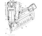
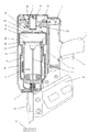
燃焼式釘打機の概要を図9を参照して説明する。燃焼式釘打機は、ハウジング14、ハンドル11、後述するスパークスイッチを操作するトリガレバー12、シリンダヘッド23、燃焼室枠15、プッシュレバー21、シリンダ4、ピストン10、ドライバブレード16、モータ8、ファン6、ガスボンベ7、点火プラグ9、排気逆止弁31、マガジン13、テールカバー1とを主に備えている。シリンダヘッド23は空気が通過可能な複数の穴を有してハウジング14の上方に設けられており、ハンドル11はハウジング14に固定されトリガレバー12が付設される。燃焼室枠15は、ハウジング14内においてハウジング14の長手方向に移動可能に設けられ、反シリンダヘッド方向にバネ付勢されるが、バネの付勢力に抗して一端がシリンダヘッド23に当接可能に設けられる。ハンドル11の図示しない後端には電池が着脱可能に装着され、電池はモータ8、点火プラグ9等の駆動用電源となる。
An outline of the combustion nailer will be described with reference to FIG. The combustion nailing machine includes a
プッシュレバー21は、ハウジング14の他端において移動可能に設けられ、燃焼室枠15と連接されている。シリンダ4は燃焼室枠15に連通可能に位置してハウジング14に固定され、燃焼室枠15の移動を案内すると共に排気穴3が形成されている。ピストン10はシリンダ4に対して往復移動可能に設けられ、燃焼室枠15の一端がシリンダヘッド23に当接した時、シリンダヘッド23、燃焼室枠15、シリンダ4のシリンダヘッド側端部と共に燃焼室5を形成する。ドライバブレード16は、ピストン10の反燃焼室側からハウジング14の他端部方向に延設されている。モータ8はシリンダヘッド23に支持され、ファン6はモータ8の回転軸に固定されて燃焼室5内に位置する。ファン6は、燃焼室5内で可燃性ガスと空気を混合して燃焼を促進させると共に燃焼室枠15がシリンダヘッド23から離間した時に、外気をハウジング14内に導入して燃焼室枠15内を掃気し、またシリンダ4の外周側を冷却する役割を果たす。ガスボンベ7はハウジング14内に収容され、シリンダヘッド23のガス通路22を通じて燃焼室5内に噴射される可燃性ガスを内含する。点火プラグ9は燃焼室5に臨み可燃性ガスと空気との混合気を着火する。排気逆止弁31は排気穴3を選択的に遮蔽する。
The
マガジン13は、ハウジング14の他端部側に設けられて釘等の止具を収容する。テールカバー1は、マガジン13内の止具をドライバブレード16に対向する位置に給送するためにマガジン13とプッシュレバー21との間に設けられている。
The
燃焼室枠15がシリンダヘッド23に当接した時に燃焼室5を密閉するために、燃焼室枠15の上部と密着するシリンダヘッド23の所定面と、燃焼室枠15の下部と密着するシリンダ4のシリンダヘッド側端部とには、シール材(シールリング)29、28がそれぞれ設けられている。なお30、25はそれぞれ初期状態においてシリンダヘッド23下方及びシリンダ4の上方に形成される空気通路であって、ハウジング14の上面を覆うヘッドカバー33から取り入れた空気をシリンダ4内外を通過させて燃焼室5、シリンダ4内の掃気及びこれらを冷却するために設けられている。
In order to seal the
プッシュレバー21を被打込材24に押し付け、トリガレバー12をオン操作すると、燃焼室5が形成された状態でハウジング14に収納されたガスボンベ7内の液化可燃性ガスが燃焼室5内に噴射され、ファン6により空気と可燃性ガスが攪拌混合され、点火プラグ9による点火によって混合気が爆発燃焼され、ピストン10を駆動してドライバブレード16を介して被打込材27に止具が打込まれる。爆発燃焼後、所定時間が経過するまでは、燃焼室枠15はシリンダヘッド23に当接した状態が維持され、燃焼ガスの排気後の排気逆止弁31の閉鎖によって燃焼室5内が密閉されると共に温度低下による燃焼室5内の圧力低下により、燃焼室5側で熱真空が得られ、ピストン上下間の圧力差によりピストン10を上昇させることができる(例えば特許文献1〜2参照)。
かかる燃焼式釘打機の特徴は、従来の圧縮空気式釘打機のようなコンプレッサとホースを必要とせず操作性が良いことである。
When the
The feature of such a combustion type nailer is that it does not require a compressor and a hose as in the conventional compressed air type nailer, and is easy to operate.
燃焼式釘打機において、プッシュレバー21を被打込材27に押し付け燃焼室枠15を燃焼室5を形成する方向に移動させない限りトリガレバー12を作動できない、すなわちトリガレバー12を操作した後にプッシュレバー21を押し付けても打ち込み動作を開始しないようにした構成となっていることは、例えば特許文献3等によって周知のことである。
In the combustion nailing machine, the
特許文献3により、プッシュレバー21を被打込材27に押し付けた状態でトリガレバー12を操作できるようにした構成が提案されたが、そのための構成が複雑で安価な燃焼式釘打機を提供し難いという問題があった。
本発明の目的は、上記した欠点をなくし、トリガレバーが先に操作されたらスパークスイッチが動作しないようにする構成を簡単なものとし安価な燃焼式釘打機を提供できるようにすることである。 SUMMARY OF THE INVENTION An object of the present invention is to eliminate the above-mentioned drawbacks and to simplify the configuration in which the spark switch does not operate when the trigger lever is operated first, and to provide an inexpensive combustion nailing machine. .
上記目的は、プッシュレバーを被打込材に押し付けてプッシュレバーを押し上げた際に他端が所定量下降してスパークスイッチのアクチュエータと接触することによりスパークスイッチをオンさせるスイッチレバーの他端を、トリガレバーが先に操作されたら下降しないようにすることにより達成される。 The purpose of the above is to press the push lever against the material to be driven and push the push lever up, the other end of the other end descends by a predetermined amount and contacts the spark switch actuator to turn on the other end of the switch lever. This is achieved by preventing the trigger lever from being lowered if it is operated first.
本発明によれば、トリガレバーが先に操作されたらスパークスイッチをオンさせるスイッチレバーの他端の下降を阻止するという簡単な構成としたので、安価な燃焼式釘打機を提供することが可能となる。 According to the present invention, it is possible to provide an inexpensive combustion nailing machine because the simple construction of preventing the lower end of the other end of the switch lever that turns on the spark switch when the trigger lever is operated first is prevented. It becomes.
本発明釘打機を一実施形態を示す図1〜図9を参照して説明する。なお上記した図9と同じ要素には同じ符号を付し、重複した説明を省略すると共に本発明に直接関係する部分につき以下説明する。 The nailing machine of the present invention will be described with reference to FIGS. 1 to 9 showing an embodiment. The same elements as those in FIG. 9 described above are denoted by the same reference numerals, redundant description is omitted, and portions directly related to the present invention will be described below.
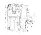
燃焼室枠15の外壁に周方向に延びて設けられた係合片15Aの移動軌跡上方に位置する一端40Aを有するスイッチレバー40はハウジング14に装着された支軸40Cを介してハウジング14に回転可能に支持され、他端40Bはトリガレバー12の上方に位置する如く形成されている。スイッチレバー40はスプリング42により図中反時計方向に付勢されている。トリガレバー12の上方にはスパークスイッチ44が装着され、スパークスイッチ44のアクチュエータ46はスパークスイッチ44の上面から上方に突出している。スパークスイッチ44は図示しない接点がオンした時に図示しない駆動回路を介して点火プラグ9を放電させるものである。なおスイッチレバー40の一端40Aには板バネ50が取り付けられ、一端40Aは板バネ50を介して係合片15Aにより押し上げれるように構成されている。板バネ50の作用については後述する。
The
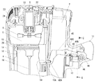
図2は操作前の初期状態を示し、図3は図2からプッシュレバー21を被打込材に押し付けプッシュレバー21が押し上げられ燃焼室5が形成された状態を示し、図4は図3からトリガレバー12が操作された状態を示す。この際、スパークスイッチ44のアクチュエータ46がスイッチレバー40の他端40Bに当接してスパークスイッチ44はオンする。図5はトリガレバー12が操作された後にプッシュレバーレバー21が押し上げられ燃焼室5が形成された状態を示すが、この際にはスイッチレバー40の他端40Bが所定量以上の下降が阻止されスパークスイッチ44のアクチュエータ46がスイッチレバー40の他端40Bに当接しなくなるのでスパークスイッチ44がオンすることはない。なおスイッチレバー40の他端40Bとスパークスイッチ44のアクチュエータ46間の距離は次のように設定されている。すなわち、図3及び図4に示す如く、プッシュレバー21が押し上げられ燃焼室5が形成された状態すなわち燃焼室枠15、係合片15Aが上死点に位置した状態で、トリガレバー12が操作された時にアクチュエータ46先端がスイッチレバー40の他端40Bと接触するような距離と設定されている。
2 shows an initial state before the operation, FIG. 3 shows a state in which the
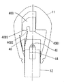
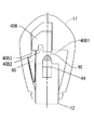
図6はスパークスイッチ44とスイッチレバー40の他端40Bの関係を示す図で、他端40Bは、横方向中央の溝部40B2、溝部40B2の両側に設けられた当接部40B1及び係止部40B3から構成されている。ハンドル11とトリガレバー12との間には固定端がハンドル11に固定されたV字状の板バネ48が設けられ、板バネ48の自由端は初期状態で溝部40B2の下方に位置するように構成されている。
FIG. 6 is a diagram showing the relationship between the
図7はトリガレバー12が先に操作された状態を示す図6相当の図で、この場合には板バネ48の自由端がトリガレバー12に押され自由端の先端が他端40Bの係止部40B3に下方に位置している状態を示す。この場合にはスイッチレバー40の他端40Bが所定量以上下降しないので、スパークスイッチ44がオンすることはない。
FIG. 7 is a view corresponding to FIG. 6 showing the state in which the
図8はプッシュレバー21が被打込材に押し当てられた後にトリガレバー12が操作された状態を示し、この場合には板バネ48の自由端が溝部40B2に位置している状態でトリガレバー12により押されるが、板バネ48の自由端が溝部40B2から外れることはなく、板バネ48が他端40Bの下降を阻止することはない。従って、図8に示す如くトリガレバー12を操作することによりスパークスイッチ44はオンするようになる。この際上記した如くスパークスイッチ44がオンするのは燃焼室5が形成された後であるので、混合気は確実に着火されて燃焼するようになる。
FIG. 8 shows a state in which the
トリガレバー12が先に操作された場合には上記した如く図5に示す状態となり、スイッチレバー40の一端40Aには大きな力が加わるが、係合片15Aと一端40A間には板バネ50が介在しており、板バネ50が衝撃を緩衝するのでスイッチレバー40が損傷を受ける恐れはなくなる。
When the
4はシリンダ、5は燃焼室、6はファン、7はガスボンベ、8はモータ、9は点火プラグ、10はピストン、12はトリガレバー、14はハウジング、15は燃焼室枠、15Aは係合片、23はシリンダヘッド、40はスイッチレバー、40Aはスイッチレバーの一端、40Bはスイッチレバーの他端、42はスプリング、44はスパークスイッチ、46はアクチュエータ、48、50は板バネ。
4 is a cylinder, 5 is a combustion chamber, 6 is a fan, 7 is a gas cylinder, 8 is a motor, 9 is a spark plug, 10 is a piston, 12 is a trigger lever, 14 is a housing, 15 is a combustion chamber frame, and 15A is an engagement piece. , 23 is a cylinder head, 40 is a switch lever, 40A is one end of the switch lever, 40B is the other end of the switch lever, 42 is a spring, 44 is a spark switch, 46 is an actuator, and 48 and 50 are leaf springs.
Claims (4)
該シリンダ内に往復移動可能に支持されたピストンと、
前記シリンダに沿って往復移動可能で前記ピストンと共に燃焼室を形成する燃焼室枠と、
前記ハウジングの下方に設けられ、被打込材への押圧時に移動可能で前記燃焼室枠と連結されたプッシュレバーと、
前記燃焼室内の混合気に点火する点火プラグと、
トリガレバーのオン操作によりオンされた時に前記点火プラグを動作させるスパークスイッチと、
前記燃焼室枠の外周に設けられた係合部と、
一端が前記係合部の移動軌跡に沿って設けられ、他端が前記スパークスイッチに対向する如く設けられたスイッチレバーとを有し、
前記トリガレバーが前記燃焼室が形成される前に操作された時に前記スイッチレバーの他端に接触してスイッチレバー他端が前記スパークスイッチに当接するのを阻止する部材を設けたことを特徴とする燃焼式釘打機。 A cylinder provided in the housing;
A piston reciprocally movably supported in the cylinder,
A combustion chamber frame forming a combustion chamber with a reciprocating movable and the piston along the cylinder,
Provided under the housing, a push lever which is connected with possible the combustion chamber frame moves in pressing to the struck member,
A spark plug to ignite the fuel-air mixture in the combustion chamber,
A spark switch for operating said spark plug when it is turned on by the ON operation of the trigger lever,
An engaging portion provided on an outer periphery of the combustion chamber frame,
One end is provided along a moving locus of the engaging portion, and a switch lever and the other end is provided as opposed to the spark switch,
Said trigger lever is provided with a member in which the switch lever and the other end in contact with the other end of the switch lever when operated before the combustion chamber is formed to prevent the contact with the Sparks acme switch Combustion type nailing machine.
Priority Applications (5)
| Application Number | Priority Date | Filing Date | Title |
|---|---|---|---|
| JP2005043280A JP4353109B2 (en) | 2005-02-18 | 2005-02-18 | Combustion nailer |
| US11/356,106 US7931181B2 (en) | 2005-02-18 | 2006-02-17 | Combustion-type power tool with trigger control arrangements |
| AT06250880T ATE438484T1 (en) | 2005-02-18 | 2006-02-18 | COMBUSTION POWERED TOOL |
| DE602006008197T DE602006008197D1 (en) | 2005-02-18 | 2006-02-18 | Combustion-powered tool |
| EP06250880A EP1693159B1 (en) | 2005-02-18 | 2006-02-18 | Combustion-type power tool |
Applications Claiming Priority (1)
| Application Number | Priority Date | Filing Date | Title |
|---|---|---|---|
| JP2005043280A JP4353109B2 (en) | 2005-02-18 | 2005-02-18 | Combustion nailer |
Publications (3)
| Publication Number | Publication Date |
|---|---|
| JP2006224271A JP2006224271A (en) | 2006-08-31 |
| JP2006224271A5 JP2006224271A5 (en) | 2007-11-15 |
| JP4353109B2 true JP4353109B2 (en) | 2009-10-28 |
Family
ID=36986069
Family Applications (1)
| Application Number | Title | Priority Date | Filing Date |
|---|---|---|---|
| JP2005043280A Active JP4353109B2 (en) | 2005-02-18 | 2005-02-18 | Combustion nailer |
Country Status (1)
| Country | Link |
|---|---|
| JP (1) | JP4353109B2 (en) |
Families Citing this family (4)
| Publication number | Priority date | Publication date | Assignee | Title |
|---|---|---|---|---|
| JP5003259B2 (en) * | 2007-04-12 | 2012-08-15 | マックス株式会社 | Gas internal combustion nailer |
| JP4945359B2 (en) | 2007-07-26 | 2012-06-06 | 株式会社マキタ | Combustion type driving tool |
| JP5365971B2 (en) * | 2008-01-31 | 2013-12-11 | 日立工機株式会社 | Combustion type driving tool |
| JP5429512B2 (en) | 2008-01-31 | 2014-02-26 | 日立工機株式会社 | Driving machine |
-
2005
- 2005-02-18 JP JP2005043280A patent/JP4353109B2/en active Active
Also Published As
| Publication number | Publication date |
|---|---|
| JP2006224271A (en) | 2006-08-31 |
Similar Documents
| Publication | Publication Date | Title |
|---|---|---|
| JP4353076B2 (en) | Combustion power tool | |
| EP2061631B1 (en) | Combustion-type power tool | |
| JP4400587B2 (en) | Driving machine | |
| US7931181B2 (en) | Combustion-type power tool with trigger control arrangements | |
| EP1595653B1 (en) | Combustion type power tool having fin for effectively cooling cylinder | |
| US7387092B2 (en) | Combustion-type power tool having cooling arrangement | |
| JP2006255880A (en) | Combustion-type power tool | |
| JP4608974B2 (en) | Combustion nailer | |
| US7305940B2 (en) | Combustion-type power tool having ignition proof arrangement | |
| JP4353109B2 (en) | Combustion nailer | |
| JP5429512B2 (en) | Driving machine | |
| JP5003259B2 (en) | Gas internal combustion nailer | |
| JP2005212060A (en) | Combustion type power tool | |
| JP4353108B2 (en) | Combustion nailer | |
| JP4586564B2 (en) | Combustion nailer | |
| JP4158598B2 (en) | Combustion power tool | |
| US20050263113A1 (en) | Combustion type nailing machine | |
| JP5293992B2 (en) | Combustion type driving machine | |
| JP4239631B2 (en) | Combustion power tool | |
| JP5262019B2 (en) | Combustion type driving machine | |
| JP2011194492A (en) | Combustion type nailing machine |
Legal Events
| Date | Code | Title | Description |
|---|---|---|---|
| A521 | Written amendment |
Free format text: JAPANESE INTERMEDIATE CODE: A523 Effective date: 20070928 |
|
| A621 | Written request for application examination |
Free format text: JAPANESE INTERMEDIATE CODE: A621 Effective date: 20070928 |
|
| A977 | Report on retrieval |
Free format text: JAPANESE INTERMEDIATE CODE: A971007 Effective date: 20090622 |
|
| TRDD | Decision of grant or rejection written | ||
| A01 | Written decision to grant a patent or to grant a registration (utility model) |
Free format text: JAPANESE INTERMEDIATE CODE: A01 Effective date: 20090707 |
|
| A01 | Written decision to grant a patent or to grant a registration (utility model) |
Free format text: JAPANESE INTERMEDIATE CODE: A01 |
|
| A61 | First payment of annual fees (during grant procedure) |
Free format text: JAPANESE INTERMEDIATE CODE: A61 Effective date: 20090720 |
|
| R150 | Certificate of patent or registration of utility model |
Ref document number: 4353109 Country of ref document: JP Free format text: JAPANESE INTERMEDIATE CODE: R150 Free format text: JAPANESE INTERMEDIATE CODE: R150 |
|
| FPAY | Renewal fee payment (event date is renewal date of database) |
Free format text: PAYMENT UNTIL: 20120807 Year of fee payment: 3 |
|
| FPAY | Renewal fee payment (event date is renewal date of database) |
Free format text: PAYMENT UNTIL: 20130807 Year of fee payment: 4 |
|
| FPAY | Renewal fee payment (event date is renewal date of database) |
Free format text: PAYMENT UNTIL: 20140807 Year of fee payment: 5 |
|
| S533 | Written request for registration of change of name |
Free format text: JAPANESE INTERMEDIATE CODE: R313533 |
|
| R350 | Written notification of registration of transfer |
Free format text: JAPANESE INTERMEDIATE CODE: R350 |