JP4352494B2 - Lens barrel - Google Patents
Lens barrel Download PDFInfo
- Publication number
- JP4352494B2 JP4352494B2 JP05292899A JP5292899A JP4352494B2 JP 4352494 B2 JP4352494 B2 JP 4352494B2 JP 05292899 A JP05292899 A JP 05292899A JP 5292899 A JP5292899 A JP 5292899A JP 4352494 B2 JP4352494 B2 JP 4352494B2
- Authority
- JP
- Japan
- Prior art keywords
- optical system
- lens barrel
- mode
- manual focus
- focusing optical
- Prior art date
- Legal status (The legal status is an assumption and is not a legal conclusion. Google has not performed a legal analysis and makes no representation as to the accuracy of the status listed.)
- Expired - Lifetime
Links
Images


Description
【0001】
【発明の属する技術分野】
本発明は、カメラ等に装着されるレンズ鏡筒に係り、詳しくは、オートフォーカスモードとマニュアルフォーカスモードとの間の迅速かつ確実な切換え等を実現する技術に関する。
【0002】
【従来の技術】
カメラには、単焦点レンズやズームレンズを始めとして、広角レンズや望遠レンズ等、種々の形式のレンズ鏡筒が装着される。レンズ鏡筒は、一枚あるいは複数枚の光学レンズからなるレンズ群を複数有しており、各レンズ群間の相対距離を適宜変動させることによりフォーカシングが行われる。そして近年では、比較的低価格帯のカメラにおいても、撮影者が鏡筒外周面のマニュアルフォーカス環を回動させてフォーカシングを行うマニュアルフォーカスモードに加え、フォーカシングをカメラ自体が行うオートフォーカスモードを備えたものが主流となっている。この種のカメラでは、カメラ本体内にマイクロコンピュータやCCDセンサ、電動モータ等からなる合焦駆動制御機構が組み込まれており、被写体までの距離が検出されると、電動モータがレンズ鏡筒内の合焦用レンズ群を前進あるいは後退駆動する構造となっている。
【0003】
通常、オートフォーカスカメラ用のレンズ鏡筒では、実開平3−26108号公報に記載されたように、鏡筒側面等に設けられたモード切換スイッチを操作することにより、オートフォーカスとマニュアルフォーカスとのモード切換えが可能となっている。モード切換スイッチは、カメラ側の合焦駆動制御機構を作動あるいは停止させる他、合焦レンズ群の駆動源を合焦駆動制御機構とマニュアルフォーカス環との間で切換えるクラッチを作動させる。すなわち、オートフォーカスモード時に撮影者がモード切換スイッチを切換えると、合焦駆動制御機構への電力供給が断たれれると同時に、合焦レンズ群保持筒に連結された連動リングの連結対象がクラッチにより合焦駆動制御機構からマニュアルフォーカス環に切換えられ、マニュアルフォーカス環の回転が連動リングに伝達される。
【0004】
【発明が解決しようとする課題】
上記公報に記載されたレンズ鏡筒では、モード切換スイッチがレンズ鏡筒に外嵌するロータリスイッチ(モード切換環)であるため、撮影時における操作性等に大きな問題があった。
【0005】
例えば、マニュアルフォーカスモードでの撮影時には、撮影者が、右手でカメラボディをホールドし、左手でレンズ鏡筒のマニュアルフォーカス環を把持して回動操作することが普通である。そのため、撮影者は、マニュアルフォーカスモードからオートフォーカスモードへの切換えにあたり、左手をマニュアルフォーカス環からモード切換環に持ち替え、モード切換環の回動操作を行わなければならない。一方、オートフォーカスモードからマニュアルフォーカスモードへの切換えにあたっては、左手をカメラボディやレンズ鏡筒からモード切換環に持ち替えて回動操作を行った後、改めて左手でマニュアルフォーカス環を把持しなければならない。通常、撮影者は被写体をファインダ内にとらえたままモード切換えを行うが、これらの操作が手探りとなるために迅速性や確実性が得難くなり、シャッターチャンスを逃す要因となる他、遠写時等においては、カメラを多少なりともぶれさせてしまい、ファインダ内の被写体を見失うこともあった。
【0006】
また、上記公報に記載されたレンズ鏡筒では、遊星歯車機構の原理により、連動リングの回転数がマニュアルフォーカス環の回転数の1/2となる。一般に、合焦駆動制御機構の減速比、合焦レンズ群保持筒に形成されたフォーカシングカムのリード角、∞位置から至近位置までのスキャンに要する駆動時間等は、カメラボディ内の駆動モータの特性と、レンズ鏡筒のフォーカシングに対する負荷トルク容量とにより自ずと決まり、マニュアルフォーカス環の∞位置から至近位置までの回転角も同様に定まってしまう。ところが、この回転角が撮影者のマニュアルフォーカシング操作に適していればよいが、過大あるいは過小であった場合には、マニュアルフォーカス環の操作量に対するファインダ内における被写体像面の移動速度が許容範囲から外れ、フォーカシング操作が非常に行い難くなる問題があった。
【0007】
本発明は上記状況に鑑みなされたもので、オートフォーカスモードとマニュアルフォーカスモードとの間の迅速かつ確実な切換えを実現すると共に、マニュアルフォーカシング時における操作性の向上を図ったレンズ鏡筒を提供することを目的とする。
【0008】
【課題を解決するための手段】
上記課題を解決するために、請求項1の発明では、合焦光学系を合焦制御装置により合焦駆動するオートフォーカスモードと、撮影者が前記合焦光学系を駆動するマニュアルフォーカスモードとを切替可能なレンズ鏡筒であって、前記マニュアルフォーカスモードのときに前記駆動のための操作を行なう操作部と、前記オートフォーカスモードと前記マニュアルフォーカスモードとのいずれのモードでも、前記合焦光学系の光軸を回転中心として回転することにより、前記合焦光学系を前記光軸方向に駆動する合焦光学系駆動部と、前記合焦制御装置による駆動量を前記合焦光学系駆動部の駆動に変換する第1の環状部と、前記操作部の操作量を前記合焦光学系駆動部の駆動に変換する第2の環状部とを含む段付アイドルローラを備え、前記第1の環状部と前記第2の環状部とは径が異なり、前記操作部は、前記マニュアルフォーカスモードのときに前記段付アイドルローラの前記第2の環状部に接触する位置と、前記オートフォーカスモードのときに前記段付アイドルローラに接触しない位置との間を移動可能であるものを提案する。
請求項2の発明では、請求項1に記載のレンズ鏡筒において、前記合焦光学系駆動部を内側に保持する固定筒を備え、前記合焦光学系駆動部は、前記固定筒に対して前記合焦光学系を相対移動させ、前記固定筒は、前記オートフォーカスモードのときは前記段付アイドルローラの前記第1の環状部に接触し、前記マニュアルフォーカスモードのときは前記段付アイドルローラに接触しないものを提案する。
請求項3の発明では、請求項1又は請求項2に記載のレンズ鏡筒において、前記合焦制御装置は、前記オートフォーカスモードのときに前記合焦光学系の光軸を回転中心として回転可能なギヤ環を備え、前記ギヤ環は、前記オートフォーカスモードと前記マニュアルフォーカスモードとのいずれのモードでも前記段付アイドルローラに接触し、前記合焦光学系駆動部は、前記オートフォーカスモードのときに、前記ギヤ環の回転に伴って前記合焦光学系を駆動するものを提案する。
請求項4の発明では、請求項3に記載のレンズ鏡筒において、前記マニュアルフォーカスモードのときに、前記ギヤ環の回転を静止させるとともに前記操作部の操作を前記段付アイドルローラに伝達させるための第1ウェーブワッシャを備えるものを提案する。
請求項5の発明では、請求項1から請求項4のいずれか1項に記載のレンズ鏡筒において、前記段付アイドルローラは、前記合焦光学系駆動部と一体的に設けられているものを提案する。
請求項6の発明では、請求項1から請求項5のいずれか1項に記載のレンズ鏡筒において、前記オートフォーカスモードと前記マニュアルフォーカスモードとの切替は、前記操作部を前記合焦光学系の光軸方向に操作することにより行なわれるものを提案する。
請求項7の発明では、請求項1から請求項6のいずれか1項に記載のレンズ鏡筒において、前記第1の環状部と前記第2の環状部とは前記合焦光学系の光軸に直交する方向に回転中心を有するものを提案する。
請求項8の発明では、請求項1から請求項7までのいずれか1項に記載のレンズ鏡筒において、前記合焦制御装置は、前記レンズ鏡筒が装着されるカメラ内に備わっているものを提案する。
【0011】
【発明の実施の形態】
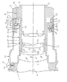
以下、本発明の一実施形態を図面に基づき説明する。図1は、本発明の一実施形態に係るレンズ鏡筒の縦断面図である。
図1において、符号1で示された部材はカメラ(図示せず)に装着される円筒形状の固定筒であり、後端部に複数個のバヨネットラグ3が形成された後部固定筒5と、鏡筒外殻の一部を形成する外部固定筒7と、第1レンズ群9および第4レンズ群11を保持する内部固定筒13とからなっている。固定筒1は、ねじ等により締結・一体化された複数個の部材から構成されているが、本実施形態では説明の便宜上単一の部材として扱う。尚、図中の符号Lはレンズ鏡筒の光軸を示している。
【0012】
後部固定筒5の前端面側には、外部固定筒7の内周面に摺接するかたちで、内周面にギヤ部21が形成された内接ギヤ環23と、この内接ギヤ環23を前方に付勢する第1の付勢部材たる第1ウェーブワッシャ25とが配設されている。また、後部固定筒5には、鏡筒側カプラ27が回動自在に支持されている。鏡筒側カプラ27は、後端に図示しないカメラ側カプラに係合するカップリング部29が形成され、前端に内接ギヤ環23のギヤ21に噛み合うピニオン31が形成されている。したがって、カメラ内の図示しないフォーカシングモータによりカメラ側カプラが回転駆動されると、その回転が鏡筒側カプラ27を介して内接ギヤ環23に伝達され、内接ギヤ環23が光軸Lを中心として正逆いずれかの方向に回転する。
【0013】
内部固定筒13には、第1レンズ群9と第4レンズ群11との間に、合焦光学系を構成する第2レンズ群33および第3レンズ群35を保持する合焦光学系保持環37が内嵌している。合焦光学系保持環37は、内部固定筒13に光軸Lを中心に回動かつ前後動自在に支持されると共に、内部固定筒13に形成されたリード溝39を貫通する複数本の連動ピン41がその外周面に突設されている。また、内部固定筒13には、後端部にフランジ43が形成された連動リング45が回動自在に外嵌しており、この連動リング45の前部に形成された直線溝47に合焦光学系保持環37の連動ピン41が係合している。したがって、連動リング45が回転駆動されると、その回転が直線溝47を介して連動ピン41に伝達され、連動ピン41がリード溝39に沿って移動することにより、合焦光学系保持環37が光軸Lに沿って進退する。
【0014】
連動リング45のフランジ43には、その外周面に突設されたピボット51を介して、複数個の段付アイドルローラ53が回動自在に支持されている。本実施形態の段付アイドルローラ53は、ゴム等の弾性体を金属筒に外嵌・固着させたものであり、その回転中心(すなわち、ピボット51の軸心)が光軸Lに直交している。段付アイドルローラ53は、図2に示したように、直径Dbの大径部53aと直径Db’の小径部53bとを有しており、図1の状態では、大径部53aの後部が内接ギヤ環23の前端面に当接する一方、大径部53aの前部が外部固定筒7の前部内側に形成された軌道環55の後端面に当接しており、第1ウェーブワッシャ25の付勢力により、段付アイドルローラ53が内接ギヤ環23と軌道環55とに挟圧されるかたちとなっている。したがって、内接ギヤ環23が回転駆動されると、内接ギヤ環23に接触した段付アイドルローラ53が軌道環55の後端面に沿って転動し、段付アイドルローラ53をフランジ43に支持した連動リング45が内接ギヤ環23の1/2の回転数で回転する。尚、連動リング45のフランジ43には、その外周面の一部に距離目盛57が形成されており、外部固定筒7の一部に嵌め込まれた透明合成樹脂製の目盛確認窓59を通して撮影距離(連動リング45の回転位置)を確認できる。
【0015】
本実施形態の場合、ディテント機構71は、マニュアルフォーカス環61の先端部と内部固定筒13との間に組み込まれている。図3(図1中のA部拡大図)に示したように、ディテント機構71は、マニュアルフォーカス環61の内周面に所定の角度範囲で刻設された前後の第1,第2環状溝73,75と、内部固定筒13の外周に穿設されたボール収納穴77と、ボール収納穴77に収納されたディテントボール79と、ディテントボール79をマニュアルフォーカス環61の内周面に付勢するコイルスプリング81とからなっている。マニュアルフォーカス環61は、第1,第2環状溝73,75にディテントボール79が侵入することで、後述するマニュアルフォーカス位置とオートフォーカス位置(すなわち、図1に示した状態)との2位置でそれぞれ係止・保持される。尚、コイルスプリング81のばね力は、マニュアルフォーカス環61が第1,第2ウェーブワッシャ25,65により前方に付勢された場合にも、マニュアルフォーカス環61をマニュアルフォーカス位置で保持できる大きさに設定されている。
【0016】
以下、本実施形態の作用を述べる。
撮影者は、オートフォーカスモードでの撮影を行う場合、右手でカメラボディをホールドし、左手でマニュアルフォーカス環61を把持する。この際、コイルスプリング81の付勢力により、図3に示したように第2環状溝75にディテントボール79が侵入するため、マニュアルフォーカス環61はオートフォーカス位置で確実に保持されて不用意に移動することがない。そして、撮影者が被写体をファインダ内にとらえると、カメラ内のマイクロコンピュータは、CCDセンサ等から入力した距離情報に応じて、合焦用電動モータやギヤ機構によりカメラ側カプラを回転させる。この回転は、カメラ側カプラに係合した鏡筒側カプラ27に伝達され、図4(図1中のB部拡大斜視図)に示したように、鏡筒側カプラ27の前端に形成されたピニオン31が正逆いずれかの回転方向(図4では、右方向)に回転する。
【0017】
ピニオン31が右方向に回転すると、ピニオン31に噛み合った内接ギヤ環23も図4中右方向に回転し、ウェーブワッシャ25によって内接ギヤ環23が前方に付勢されていることから、内接ギヤ環23の前端面に当接した段付アイドルローラ53が図4中左方向に回転する。そして、オートフォーカスモードにおいては、段付アイドルローラ53は、その大径部53aが外部固定筒7の軌道環55に当接しているため、軌道環55の後端面に沿って図4中右方向に転動する。この際、段付アイドルローラ53は、光軸Lと直交する方向に回転中心を有するため、内接ギヤ環23や軌道環55とは円滑に転接することになり、耐久性や異音の原因となる転接面の摩耗やスリップが殆ど生じない。
【0018】
段付アイドルローラ53が転動すると、連動リング45も、フランジ43に固着されたピボット51を介して段付アイドルローラ53を支持しているため、図4中右方向に内接ギヤ環23の1/2の回転数をもって回転する。連動リング45が回転すると、この回転は、連動リング45に形成された直線溝47を介して、合焦光学系保持環37に固着された連動ピン41に伝達される。連動ピン41は、内部固定筒13のリード溝39にも係合しているため、リード溝39の傾斜により光軸Lに沿って進退する。これにより、連動ピン41と一体の合焦光学系保持環37も進退し、合焦光学系保持環37に保持された第2レンズ群33および第3レンズ群35が光軸Lに沿って移動し、オートフォーカシングが実現される。
【0019】
さて、撮影者は、ファインダ内に被写体をとらえたままで、オートフォーカスモードからマニュアルフォーカスモードに切換える場合、図5に示したように、所定の力でマニュアルフォーカス環61を後方に引き寄せる。すると、図6(図5中のC部拡大図)に示したように第2環状溝73にディテントボール79が侵入するため、撮影者が手を離してもマニュアルフォーカス環61はマニュアルフォーカス位置で保持される。この状態において、マニュアルフォーカス環61のローラ駆動環63は、その後端面が第1ウェーブワッシャ25の付勢力に打勝って段付アイドルローラ53の小径部53bに当接した後、第2ウェーブワッシャ65の付勢力に打勝って段付アイドルローラ53を後方に押圧する。これにより、段付アイドルローラ53は、連動リング45および内接ギヤ環23と伴に所定量後退し、段付アイドルローラ53の大径部53aと軌道環55との間には間隙が形成される。
【0020】
一方、マニュアルフォーカス環61が後退すると、ローラ駆動環63に固着されたブラシ67が外部固定筒7に貼着されたフレキシブルプリント基板69上を後退する。これにより、レンズ鏡筒側の信号処理基盤からカメラ側のマイクロコンピュータにマニュアルフォーカスモードであることを示す信号が出力され、カメラ内では電動モータの駆動が停止される。この状態では、第1ウェーブワッシャ25が光軸L方向に圧縮されるため、内接ギヤ環23の後面と第1ウェーブワッシャ25の前面との間には所定の摩擦力が発生する。本実施形態の場合、この摩擦力が連動リング45の回転に要する回転トルクより大きくなるように、第1ウェーブワッシャ25のばね常数や内接ギヤ環23と第1ウェーブワッシャ25との間の摩擦係数が設定されている。
【0021】
この状態で、図7(図5中のD部拡大斜視図)に示したように、撮影者がマニュアルフォーカス環61を図7中右方向に回動させると、ローラ駆動環63の後端面に当接した段付アイドルローラ53も図7中右方向に回転する。そして、マニュアルフォーカスモードにおいては、段付アイドルローラ53は、大径部53aが圧接した内接ギヤ環23が上述した第1ウェーブワッシャ25との摩擦力により静止しているため、内接ギヤ環23の前端面に沿って図7中右方向に転動する。
【0022】
段付アイドルローラ53が転動すると、段付アイドルローラ53を支持した連動リング45も図7中右方向に回転する。そして、図8において、内接ギヤ環23における段付アイドルローラ53の大径部53aとの当接部位の径をDa、ローラ駆動環63における段付アイドルローラ53の小径部53bとの当接部位の径をDcとすると、大径部53aの直径がDb、小径部53bの直径がDb’であるから、遊星歯車機構の原理により、ローラ駆動環63の1回転あたりの連動リング45の回転数NはDb・Dc/(Da・Db’+Db・Dc)となる。したがって、段付アイドルローラ53の大径部53aの外径Dbや小径部53bの外径Db’を適宜増減させることにより、ローラ駆動環63の回動量(すなわち、マニュアルフォーカス環61の操作量)に対する連動リング45の回動量(すなわち、合焦光学系保持環37の進退量)を任意に設定することが可能となる。
【0023】
このように、本実施形態のレンズ鏡筒では、マニュアルフォーカス環61を把持したままで迅速にモード切換えを行うことが可能となるため、その操作性が従来装置に較べて飛躍的に向上すると共に、モード切換時にファインダ内にとらえた被写体を見失うこと等が少なくなる。また、マニュアルフォーカス環61は、ディテント機構71によりオートフォーカス位置とマニュアルフォーカス位置とで係止・保持されるため、操作性が非常に良好となる。更に、撮影者によるマニュアルフォーカス環61の操作量と、連動リング45の回動量との比が自在に設定できるため、種々の仕様のレンズ鏡筒においても最適なフォーカシング操作性を得ることが可能となる。
【0024】
以上で具体的実施形態の説明を終えるが、本発明の態様はこの実施形態に限られるものではない。例えば、上記実施形態では、オートフォーカスモードからマニュアルフォーカスモードへの切換時にマニュアルフォーカス環を後方に引き寄せるものとしたが、前方に押し出すようにしてもよい。また、上記実施形態では、ディテント機構として、環状溝とディテントボールとからなるものを採用したが、ディテントピンや板ばねを用いたものもの等、種々の構造が採用し得る。また、上記実施形態では、段付アイドルローラの大径部を軌道環に転接させ、小径部をローラ駆動環に転接させるようにしたが、この関係を逆にしてもよい。また、上記実施形態は、本発明を4群形式のレンズ鏡筒に適用したものであるが、他の形式のレンズ鏡筒に適用してもよい。更に、フォーカス機構等の具体的構成等についても、上記実施形態での例示に限られるものではなく、設計上の都合等により適宜変更可能である。
【0025】
【発明の効果】
本発明の一態様によれば、合焦制御装置が回転駆動装置を介して合焦光学系を駆動制御するオートフォーカスモードと、撮影者が前記合焦光学系を駆動するマニュアルフォーカスモードとが選択可能なレンズ鏡筒であって、連動リングと該連動リングにカム機構を介して連結された合焦光学系保持部材とからなり、該連動リングへの回転入力に応じて該合焦光学系保持部材を固定筒に対し光軸に沿って移動させる合焦光学系移動装置と、前記オートフォーカスモードを選択するオートフォーカス位置と、前記マニュアルフォーカスモードを選択するマニュアルフォーカス位置とに前記固定筒に対して前後移動可能で、かつ、マニュアルフォーカス位置に切換えられた際には、手動による回動操作が可能となるマニュアルフォーカス環と、前記マニュアルフォーカス環がオートフォーカス位置に切り換えられたときには、前記回転駆動装置の回転力を前記連動リングに伝達する一方、前記マニュアルフォーカス環がマニュアルフォーカス位置に切り換えられたときには、該マニュアルフォーカス環の回転力を前記連動リングに伝達するクラッチ装置と、前記マニュアルフォーカス環を前記オートフォーカス位置あるいは前記マニュアルフォーカス位置でそれぞれ保持するディテント機構とを備えたため、撮影者がマニュアルフォーカス環を把持したままでこれを前方あるいは後方に移動させることによりモード切換が迅速かつ容易に行われるようになり、シャッターチャンスを逃したり、ファインダ内の被写体を見失う頻度が少なくなる他、マニュアルフォーカス環がオートフォーカス位置とマニュアルフォーカス位置とで保持されるために良好な操作性が得られる。
【図面の簡単な説明】
【図1】本発明に係るレンズ鏡筒のオートフォーカスモード時を示す縦断面図である。
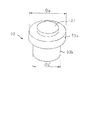
【図2】段付アイドルローラを示す斜視図である。
【図3】図1中のA部拡大斜視図である。
【図4】図1中のB部拡大斜視図である。
【図5】本発明に係るレンズ鏡筒のマニュアルフォーカスモード時を示す縦断面図である。
本発明の一実施形態に係るレンズ鏡筒の要部を示す縦断面図である。
【図6】図5中のC部拡大斜視図である。
【図7】図5中のD部拡大斜視図である。
【図8】段付アイドルローラの作用を示す説明図である。
【符号の説明】
1‥‥固定筒
5‥‥後部固定筒
7‥‥外部固定筒
13‥‥内部固定筒
23‥‥内接ギヤ環
25‥‥第1ウェーブワッシャ
27‥‥鏡筒側カプラ
31‥‥ピニオン
33‥‥第2レンズ群
35‥‥第3レンズ群
37‥‥合焦光学系保持環
39‥‥リード溝
41‥‥連動ピン
45‥‥連動リング
53‥‥段付アイドルローラ
55‥‥軌道環
61‥‥マニュアルフォーカス環
63‥‥ローラ駆動環
65‥‥第2ウェーブワッシャ
67‥‥ブラシ
69‥‥フレキシブルプリント基板
71‥‥ディテント機構
73‥‥第1環状溝
75‥‥第2環状溝
79‥‥ディテントボール
81‥‥コイルスプリング
L‥‥光軸[0001]
BACKGROUND OF THE INVENTION
The present invention relates to a lens barrel mounted on a camera or the like, and more particularly, to a technique that realizes quick and reliable switching between an autofocus mode and a manual focus mode.
[0002]
[Prior art]
Various types of lens barrels such as a wide-angle lens and a telephoto lens are mounted on the camera, including a single focus lens and a zoom lens. The lens barrel has a plurality of lens groups including one or a plurality of optical lenses, and focusing is performed by appropriately changing the relative distance between the lens groups. In recent years, even relatively low-price cameras have an autofocus mode in which the camera itself performs focusing in addition to the manual focus mode in which the photographer rotates the manual focus ring on the outer peripheral surface of the lens barrel. The mainstream is the mainstream. In this type of camera, a focusing drive control mechanism including a microcomputer, a CCD sensor, an electric motor, and the like is incorporated in the camera body. When the distance to the subject is detected, the electric motor is installed in the lens barrel. The focusing lens group is driven forward or backward.
[0003]
Normally, in a lens barrel for an autofocus camera, as described in Japanese Utility Model Laid-Open No. 3-26108, by operating a mode change switch provided on the side surface of the barrel or the like, autofocus and manual focus can be switched. Mode switching is possible. The mode changeover switch activates or stops the focusing drive control mechanism on the camera side, and activates a clutch that switches the driving source of the focusing lens group between the focusing drive control mechanism and the manual focus ring. That is, when the photographer switches the mode switch in the auto focus mode, the power supply to the focusing drive control mechanism is cut off, and at the same time, the interlocking ring connected to the focusing lens group holding cylinder is connected by the clutch. The focus drive control mechanism is switched to the manual focus ring, and the rotation of the manual focus ring is transmitted to the interlocking ring.
[0004]
[Problems to be solved by the invention]
In the lens barrel described in the above publication, since the mode change switch is a rotary switch (mode change ring) that is externally fitted to the lens barrel, there is a large problem in operability during photographing.
[0005]
For example, when photographing in the manual focus mode, it is common for the photographer to hold the camera body with the right hand and hold and rotate the manual focus ring of the lens barrel with the left hand. Therefore, the photographer must change the left hand from the manual focus ring to the mode switching ring and perform the rotation operation of the mode switching ring when switching from the manual focus mode to the auto focus mode. On the other hand, when switching from the auto focus mode to the manual focus mode, the left hand must be moved from the camera body or lens barrel to the mode switching ring, and then the manual focus ring must be held again with the left hand. . Normally, the photographer switches the mode while keeping the subject in the viewfinder, but these operations are frustrating, so it is difficult to obtain speediness and certainty, and this may cause a missed photo opportunity. In some cases, the camera is slightly shaken and the subject in the viewfinder is lost.
[0006]
Further, in the lens barrel described in the above publication, the rotation speed of the interlocking ring is ½ of the rotation speed of the manual focus ring due to the principle of the planetary gear mechanism. In general, the reduction ratio of the focusing drive control mechanism, the lead angle of the focusing cam formed on the focusing lens group holding cylinder, the drive time required for scanning from the ∞ position to the closest position, etc., are the characteristics of the drive motor in the camera body. And the load torque capacity for focusing of the lens barrel is naturally determined, and the rotation angle from the ∞ position to the closest position of the manual focus ring is similarly determined. However, this rotation angle only needs to be suitable for the manual focusing operation of the photographer, but if it is too large or too small, the moving speed of the subject image plane in the viewfinder with respect to the operation amount of the manual focus ring is out of the allowable range. There is a problem that the focusing operation becomes very difficult.
[0007]
The present invention has been made in view of the above circumstances, and provides a lens barrel that realizes quick and reliable switching between an autofocus mode and a manual focus mode and an improvement in operability during manual focusing. For the purpose.
[0008]
[Means for Solving the Problems]
In order to solve the above problems, in the invention of
According to a second aspect of the present invention, in the lens barrel according to the first aspect of the present invention, the lens barrel includes a fixed cylinder that holds the focusing optical system driving unit on the inner side, and the focusing optical system driving unit is in contact with the fixed cylinder. The focusing optical system is relatively moved, and the fixed cylinder contacts the first annular portion of the stepped idler roller in the autofocus mode, and the stepped idler roller in the manual focus mode. Suggest something that doesn't touch
According to a third aspect of the present invention, in the lens barrel according to the first or second aspect, the focusing control device can rotate around the optical axis of the focusing optical system in the autofocus mode. The gear ring is in contact with the stepped idler roller in any of the autofocus mode and the manual focus mode, and the focusing optical system drive unit is in the autofocus mode. Furthermore, it is proposed to drive the focusing optical system as the gear ring rotates.
According to a fourth aspect of the present invention, in the lens barrel according to the third aspect, in the manual focus mode, the rotation of the gear ring is stopped and the operation of the operation unit is transmitted to the stepped idler roller. A first wave washer is proposed.
According to a fifth aspect of the present invention, in the lens barrel according to any one of the first to fourth aspects, the stepped idler roller is provided integrally with the focusing optical system driving unit. Propose.
According to a sixth aspect of the present invention, in the lens barrel according to any one of the first to fifth aspects, the switching between the autofocus mode and the manual focus mode is performed by moving the operation unit to the focusing optical system. We propose what is done by operating in the direction of the optical axis.
According to a seventh aspect of the present invention, in the lens barrel according to any one of the first to sixth aspects, the first annular portion and the second annular portion are optical axes of the focusing optical system. We propose the one with the center of rotation in the direction orthogonal to.
According to an eighth aspect of the present invention, in the lens barrel according to any one of the first to seventh aspects, the focusing control device is provided in a camera to which the lens barrel is mounted. Propose.
[0011]
DETAILED DESCRIPTION OF THE INVENTION
Hereinafter, an embodiment of the present invention will be described with reference to the drawings. FIG. 1 is a longitudinal sectional view of a lens barrel according to an embodiment of the present invention.
In FIG. 1, a member denoted by
[0012]
On the front end face side of the rear
[0013]
The internal fixed
[0014]
A plurality of stepped
[0015]
In the case of the present embodiment, the
[0016]
The operation of this embodiment will be described below.
When photographing in the autofocus mode, the photographer holds the camera body with the right hand and holds the
[0017]
When the
[0018]
When the stepped
[0019]
When the photographer switches from the autofocus mode to the manual focus mode while keeping the subject in the viewfinder, as shown in FIG. 5, the photographer pulls the
[0020]
On the other hand, when the
[0021]
In this state, as shown in FIG. 7 (part D enlarged perspective view in FIG. 5), when the photographer rotates the
[0022]
When the stepped
[0023]
As described above, in the lens barrel of the present embodiment, since it is possible to quickly switch modes while holding the
[0024]
Although description of specific embodiment is finished above, the aspect of the present invention is not limited to this embodiment. For example, in the above embodiment, the manual focus ring is drawn backward when switching from the autofocus mode to the manual focus mode, but it may be pushed forward. In the above embodiment, the detent mechanism includes an annular groove and a detent ball. However, various structures such as those using a detent pin or a leaf spring can be used. In the above embodiment, the large-diameter portion of the stepped idle roller is brought into rolling contact with the raceway ring and the small-diameter portion is brought into rolling contact with the roller driving ring. However, this relationship may be reversed. In the above embodiment, the present invention is applied to a four-group lens barrel. However, the present invention may be applied to other types of lens barrels. Furthermore, the specific configuration and the like of the focus mechanism and the like are not limited to the examples in the above embodiment, and can be appropriately changed depending on the design convenience.
[0025]
【The invention's effect】
According to one aspect of the present invention , an autofocus mode in which the focusing control device drives and controls the focusing optical system via the rotation driving device and a manual focus mode in which the photographer drives the focusing optical system are selected. A lens barrel, which includes an interlocking ring and a focusing optical system holding member connected to the interlocking ring via a cam mechanism, and holds the focusing optical system in response to rotational input to the interlocking ring. A focusing optical system moving device that moves a member along the optical axis with respect to the fixed cylinder, an autofocus position for selecting the autofocus mode, and a manual focus position for selecting the manual focus mode with respect to the fixed cylinder A manual focus ring that can be manually rotated when switched to the manual focus position; When the manual focus ring is switched to the autofocus position, the rotational force of the rotary drive device is transmitted to the interlocking ring, while when the manual focus ring is switched to the manual focus position, the rotational force of the manual focus ring is transmitted. And a detent mechanism for holding the manual focus ring at the autofocus position or the manual focus position, respectively, so that the photographer can hold the manual focus ring forward while holding the manual focus ring. By moving backward, the mode can be switched quickly and easily, and the chance of missing a photo opportunity or losing sight of the subject in the viewfinder is reduced. Good operability is obtained to be held at the positions and manual focus position.
[Brief description of the drawings]
FIG. 1 is a longitudinal sectional view showing an autofocus mode of a lens barrel according to the present invention.
FIG. 2 is a perspective view showing a stepped idle roller.
FIG. 3 is an enlarged perspective view of a part A in FIG.
4 is an enlarged perspective view of a portion B in FIG. 1. FIG.
FIG. 5 is a longitudinal sectional view showing a lens barrel according to the present invention in a manual focus mode.
It is a longitudinal cross-sectional view which shows the principal part of the lens barrel which concerns on one Embodiment of this invention.
6 is an enlarged perspective view of a C part in FIG. 5. FIG.
7 is an enlarged perspective view of a D part in FIG. 5. FIG.
FIG. 8 is an explanatory diagram showing the operation of a stepped idle roller.
[Explanation of symbols]
DESCRIPTION OF
Claims (8)
前記マニュアルフォーカスモードのときに前記駆動のための操作を行なう操作部と、
前記オートフォーカスモードと前記マニュアルフォーカスモードとのいずれのモードでも、前記合焦光学系の光軸を回転中心として回転することにより、前記合焦光学系を前記光軸方向に駆動する合焦光学系駆動部と、
前記合焦制御装置による駆動量を前記合焦光学系駆動部の駆動に変換する第1の環状部と、前記操作部の操作量を前記合焦光学系駆動部の駆動に変換する第2の環状部とを含む段付アイドルローラを備え、
前記第1の環状部と前記第2の環状部とは径が異なり、
前記操作部は、前記マニュアルフォーカスモードのときに前記段付アイドルローラの前記第2の環状部に接触する位置と、前記オートフォーカスモードのときに前記段付アイドルローラに接触しない位置との間を移動可能であることを特徴とするレンズ鏡筒。A lens barrel capable of switching between an autofocus mode in which a focusing optical system is driven by a focusing control device and a manual focus mode in which a photographer drives the focusing optical system;
An operation unit for performing an operation for the driving in the manual focus mode;
In any of the auto focus mode and the manual focus mode, the focusing optical system that drives the focusing optical system in the optical axis direction by rotating about the optical axis of the focusing optical system. A drive unit;
A first annular portion that converts the drive amount of the focus control device into drive of the focus optical system drive portion; and a second annular portion that converts the operation amount of the operation portion into drive of the focus optical system drive portion. A stepped idler roller including an annular portion,
The first annular portion and the second annular portion have different diameters,
The operation portion is between a position that contacts the second annular portion of the stepped idle roller in the manual focus mode and a position that does not contact the stepped idler roller in the autofocus mode. A lens barrel that is movable.
前記合焦光学系駆動部を内側に保持する固定筒を備え、
前記合焦光学系駆動部は、前記固定筒に対して前記合焦光学系を相対移動させ、
前記固定筒は、前記オートフォーカスモードのときは前記段付アイドルローラの前記第1の環状部に接触し、前記マニュアルフォーカスモードのときは前記段付アイドルローラに接触しないことを特徴とするレンズ鏡筒。The lens barrel according to claim 1,
A fixed cylinder for holding the focusing optical system driving unit inside;
The focusing optical system driving unit moves the focusing optical system relative to the fixed cylinder,
The fixed mirror is in contact with the first annular portion of the stepped idler roller in the autofocus mode, and is not in contact with the stepped idler roller in the manual focus mode. Tube.
前記合焦制御装置は、前記オートフォーカスモードのときに前記合焦光学系の光軸を回転中心として回転可能なギヤ環を備え、
前記ギヤ環は、前記オートフォーカスモードと前記マニュアルフォーカスモードとのいずれのモードでも前記段付アイドルローラに接触し、
前記合焦光学系駆動部は、前記オートフォーカスモードのときに、前記ギヤ環の回転に伴って前記合焦光学系を駆動することを特徴とするレンズ鏡筒。In the lens barrel according to claim 1 or 2,
The focusing control device includes a gear ring that can rotate around the optical axis of the focusing optical system in the autofocus mode,
The gear ring contacts the stepped idler roller in any of the autofocus mode and the manual focus mode,
The lens barrel characterized in that the focusing optical system driving unit drives the focusing optical system in accordance with the rotation of the gear ring in the autofocus mode.
前記マニュアルフォーカスモードのときに、前記ギヤ環の回転を静止させるとともに前記操作部の操作を前記段付アイドルローラに伝達させるための第1ウェーブワッシャを備えることを特徴とするレンズ鏡筒。In the lens barrel according to claim 3,
A lens barrel comprising a first wave washer for stopping the rotation of the gear ring and transmitting the operation of the operation unit to the stepped idler roller in the manual focus mode.
前記段付アイドルローラは、前記合焦光学系駆動部と一体的に設けられていることを特徴とするレンズ鏡筒。In the lens barrel according to any one of claims 1 to 4 ,
The lens barrel, wherein the stepped idler roller is provided integrally with the focusing optical system driving unit.
前記オートフォーカスモードと前記マニュアルフォーカスモードとの切替は、前記操作部を前記合焦光学系の光軸方向に操作することにより行なわれることを特徴とするレンズ鏡筒。In the lens barrel according to any one of claims 1 to 5 ,
Switching between the autofocus mode and the manual focus mode is performed by operating the operation unit in an optical axis direction of the focusing optical system.
前記第1の環状部と前記第2の環状部とは前記合焦光学系の光軸に直交する方向に回転中心を有することを特徴とするレンズ鏡筒。In the lens barrel according to any one of claims 1 to 6 ,
The lens barrel characterized in that the first annular portion and the second annular portion have a rotation center in a direction perpendicular to the optical axis of the focusing optical system.
前記合焦制御装置は、前記レンズ鏡筒が装着されるカメラ内に備わっていることを特徴とするレンズ鏡筒。In the lens barrel according to any one of claims 1 to 7 ,
The focus control device is provided in a camera to which the lens barrel is mounted.
Priority Applications (1)
| Application Number | Priority Date | Filing Date | Title |
|---|---|---|---|
| JP05292899A JP4352494B2 (en) | 1999-03-01 | 1999-03-01 | Lens barrel |
Applications Claiming Priority (1)
| Application Number | Priority Date | Filing Date | Title |
|---|---|---|---|
| JP05292899A JP4352494B2 (en) | 1999-03-01 | 1999-03-01 | Lens barrel |
Publications (3)
| Publication Number | Publication Date |
|---|---|
| JP2000249892A JP2000249892A (en) | 2000-09-14 |
| JP2000249892A5 JP2000249892A5 (en) | 2006-05-11 |
| JP4352494B2 true JP4352494B2 (en) | 2009-10-28 |
Family
ID=12928514
Family Applications (1)
| Application Number | Title | Priority Date | Filing Date |
|---|---|---|---|
| JP05292899A Expired - Lifetime JP4352494B2 (en) | 1999-03-01 | 1999-03-01 | Lens barrel |
Country Status (1)
| Country | Link |
|---|---|
| JP (1) | JP4352494B2 (en) |
Families Citing this family (4)
| Publication number | Priority date | Publication date | Assignee | Title |
|---|---|---|---|---|
| JP5122393B2 (en) * | 2008-07-30 | 2013-01-16 | カヤバ システム マシナリー株式会社 | Oscillating rotation test equipment |
| JP5482577B2 (en) * | 2010-08-31 | 2014-05-07 | コニカミノルタ株式会社 | Lens barrel |
| JP6946675B2 (en) * | 2017-03-13 | 2021-10-06 | 株式会社リコー | Lens barrel and imaging device |
| JP7206996B2 (en) * | 2019-02-20 | 2023-01-18 | 株式会社リコー | Lens barrel and camera |
-
1999
- 1999-03-01 JP JP05292899A patent/JP4352494B2/en not_active Expired - Lifetime
Also Published As
| Publication number | Publication date |
|---|---|
| JP2000249892A (en) | 2000-09-14 |
Similar Documents
| Publication | Publication Date | Title |
|---|---|---|
| JP2597707B2 (en) | Lens barrel | |
| US7338219B2 (en) | Retractable lens system and a camera incorporating the retractable lens system | |
| US5937215A (en) | Camera having a zoom lens | |
| US7595937B2 (en) | Lens apparatus and image-pickup apparatus | |
| JP4654007B2 (en) | Camera system with seamless lens drive switching mechanism | |
| JP2990795B2 (en) | Lens barrel using surface wave motor | |
| JP2010281971A (en) | Interchangeable lens and imaging device | |
| JP4193748B2 (en) | Retractable lens barrel and imaging device | |
| JP4931300B2 (en) | Retractable camera with zoom lens | |
| JP4352494B2 (en) | Lens barrel | |
| JPH09203849A (en) | Lens barrel of camera | |
| JP3201418B2 (en) | Variable focus device | |
| US5420721A (en) | Lens barrel | |
| JPH1164708A (en) | Zoom lens barrel | |
| JP4013309B2 (en) | Lens barrel | |
| JPH08234259A (en) | Reference position detecting device for lens barrel | |
| JPH11295582A (en) | Lens barrel | |
| JP2566397B2 (en) | Lens drive | |
| JP3124089B2 (en) | Lens barrel for autofocus camera | |
| JPH09281378A (en) | Surface wave motor incorporating lens barrel | |
| JP3571415B2 (en) | Viewfinder drive mechanism | |
| US6771897B2 (en) | Lens barrel and camera | |
| JP2769609B2 (en) | camera | |
| JP2003098417A (en) | Zoom lens barrel | |
| JP2666837B2 (en) | Shooting lens capable of automatic manual focusing |
Legal Events
| Date | Code | Title | Description |
|---|---|---|---|
| A621 | Written request for application examination |
Free format text: JAPANESE INTERMEDIATE CODE: A621 Effective date: 20060227 |
|
| A521 | Written amendment |
Free format text: JAPANESE INTERMEDIATE CODE: A523 Effective date: 20060313 |
|
| A131 | Notification of reasons for refusal |
Free format text: JAPANESE INTERMEDIATE CODE: A131 Effective date: 20081111 |
|
| A521 | Written amendment |
Free format text: JAPANESE INTERMEDIATE CODE: A523 Effective date: 20090108 |
|
| A131 | Notification of reasons for refusal |
Free format text: JAPANESE INTERMEDIATE CODE: A131 Effective date: 20090331 |
|
| A521 | Written amendment |
Free format text: JAPANESE INTERMEDIATE CODE: A523 Effective date: 20090514 |
|
| TRDD | Decision of grant or rejection written | ||
| A01 | Written decision to grant a patent or to grant a registration (utility model) |
Free format text: JAPANESE INTERMEDIATE CODE: A01 Effective date: 20090707 |
|
| A01 | Written decision to grant a patent or to grant a registration (utility model) |
Free format text: JAPANESE INTERMEDIATE CODE: A01 |
|
| A61 | First payment of annual fees (during grant procedure) |
Free format text: JAPANESE INTERMEDIATE CODE: A61 Effective date: 20090720 |
|
| R150 | Certificate of patent or registration of utility model |
Free format text: JAPANESE INTERMEDIATE CODE: R150 |
|
| FPAY | Renewal fee payment (event date is renewal date of database) |
Free format text: PAYMENT UNTIL: 20120807 Year of fee payment: 3 |
|
| FPAY | Renewal fee payment (event date is renewal date of database) |
Free format text: PAYMENT UNTIL: 20120807 Year of fee payment: 3 |
|
| FPAY | Renewal fee payment (event date is renewal date of database) |
Free format text: PAYMENT UNTIL: 20150807 Year of fee payment: 6 |
|
| S531 | Written request for registration of change of domicile |
Free format text: JAPANESE INTERMEDIATE CODE: R313531 |
|
| FPAY | Renewal fee payment (event date is renewal date of database) |
Free format text: PAYMENT UNTIL: 20150807 Year of fee payment: 6 |
|
| R350 | Written notification of registration of transfer |
Free format text: JAPANESE INTERMEDIATE CODE: R350 |
|
| FPAY | Renewal fee payment (event date is renewal date of database) |
Free format text: PAYMENT UNTIL: 20150807 Year of fee payment: 6 |
|
| R250 | Receipt of annual fees |
Free format text: JAPANESE INTERMEDIATE CODE: R250 |
|
| R250 | Receipt of annual fees |
Free format text: JAPANESE INTERMEDIATE CODE: R250 |
|
| R250 | Receipt of annual fees |
Free format text: JAPANESE INTERMEDIATE CODE: R250 |
|
| EXPY | Cancellation because of completion of term |